JP2006068898A - Milling tools, especially thread milling - Google Patents
Milling tools, especially thread milling Download PDFInfo
- Publication number
- JP2006068898A JP2006068898A JP2005255174A JP2005255174A JP2006068898A JP 2006068898 A JP2006068898 A JP 2006068898A JP 2005255174 A JP2005255174 A JP 2005255174A JP 2005255174 A JP2005255174 A JP 2005255174A JP 2006068898 A JP2006068898 A JP 2006068898A
- Authority
- JP
- Japan
- Prior art keywords
- cutting insert
- cutting
- milling tool
- tool
- milling
- Prior art date
- Legal status (The legal status is an assumption and is not a legal conclusion. Google has not performed a legal analysis and makes no representation as to the accuracy of the status listed.)
- Pending
Links
Images


Classifications
-
- B—PERFORMING OPERATIONS; TRANSPORTING
- B23—MACHINE TOOLS; METAL-WORKING NOT OTHERWISE PROVIDED FOR
- B23G—THREAD CUTTING; WORKING OF SCREWS, BOLT HEADS, OR NUTS, IN CONJUNCTION THEREWITH
- B23G5/00—Thread-cutting tools; Die-heads
- B23G5/18—Milling cutters
-
- B—PERFORMING OPERATIONS; TRANSPORTING
- B23—MACHINE TOOLS; METAL-WORKING NOT OTHERWISE PROVIDED FOR
- B23C—MILLING
- B23C5/00—Milling-cutters
- B23C5/16—Milling-cutters characterised by physical features other than shape
- B23C5/20—Milling-cutters characterised by physical features other than shape with removable cutter bits or teeth or cutting inserts
- B23C5/22—Securing arrangements for bits or teeth or cutting inserts
- B23C5/2239—Securing arrangements for bits or teeth or cutting inserts with cutting inserts clamped by a clamping member acting almost perpendicular on the cutting face
- B23C5/2243—Securing arrangements for bits or teeth or cutting inserts with cutting inserts clamped by a clamping member acting almost perpendicular on the cutting face for plate-like cutting inserts
-
- Y—GENERAL TAGGING OF NEW TECHNOLOGICAL DEVELOPMENTS; GENERAL TAGGING OF CROSS-SECTIONAL TECHNOLOGIES SPANNING OVER SEVERAL SECTIONS OF THE IPC; TECHNICAL SUBJECTS COVERED BY FORMER USPC CROSS-REFERENCE ART COLLECTIONS [XRACs] AND DIGESTS
- Y10—TECHNICAL SUBJECTS COVERED BY FORMER USPC
- Y10T—TECHNICAL SUBJECTS COVERED BY FORMER US CLASSIFICATION
- Y10T407/00—Cutters, for shaping
- Y10T407/19—Rotary cutting tool
- Y10T407/1906—Rotary cutting tool including holder [i.e., head] having seat for inserted tool
-
- Y—GENERAL TAGGING OF NEW TECHNOLOGICAL DEVELOPMENTS; GENERAL TAGGING OF CROSS-SECTIONAL TECHNOLOGIES SPANNING OVER SEVERAL SECTIONS OF THE IPC; TECHNICAL SUBJECTS COVERED BY FORMER USPC CROSS-REFERENCE ART COLLECTIONS [XRACs] AND DIGESTS
- Y10—TECHNICAL SUBJECTS COVERED BY FORMER USPC
- Y10T—TECHNICAL SUBJECTS COVERED BY FORMER US CLASSIFICATION
- Y10T407/00—Cutters, for shaping
- Y10T407/23—Cutters, for shaping including tool having plural alternatively usable cutting edges
-
- Y—GENERAL TAGGING OF NEW TECHNOLOGICAL DEVELOPMENTS; GENERAL TAGGING OF CROSS-SECTIONAL TECHNOLOGIES SPANNING OVER SEVERAL SECTIONS OF THE IPC; TECHNICAL SUBJECTS COVERED BY FORMER USPC CROSS-REFERENCE ART COLLECTIONS [XRACs] AND DIGESTS
- Y10—TECHNICAL SUBJECTS COVERED BY FORMER USPC
- Y10T—TECHNICAL SUBJECTS COVERED BY FORMER US CLASSIFICATION
- Y10T409/00—Gear cutting, milling, or planing
- Y10T409/30—Milling
- Y10T409/300056—Thread or helix generating
Landscapes
- Engineering & Computer Science (AREA)
- Mechanical Engineering (AREA)
- Milling Processes (AREA)
- Cutting Tools, Boring Holders, And Turrets (AREA)
Abstract
【課題】 フライス工具、特にねじフライス。
【解決手段】 ねじフライス(11)は、クランプシャフト(13)とフライスシャフト(14)を備えた工具ホルダ(12)を有している。この工具ホルダ内へ、切断刃(21)を有する切断挿入片(15)が挿入され、その切断刃はねじ切断プロフィールを有している。切断挿入片は、ねじ孔(17)内へ挿入された、締付けボルト(16)によって保持される。締付けボルト(16)は、切断挿入片の互いに対して平行に延びる側面(24)へ直角に作用する。
フライスシャフト(14)内のそれぞれ3つのねじ孔(17)は、それぞれフライスシャフトの半径方向平面内にねじ孔が一つだけ存在するように、互いに対して変位されている。
【選択図】 図2PROBLEM TO BE SOLVED: To mill a tool, particularly a screw mill.
A screw mill (11) has a tool holder (12) having a clamp shaft (13) and a milling shaft (14). A cutting insert (15) having a cutting blade (21) is inserted into the tool holder, the cutting blade having a thread cutting profile. The cutting insert piece is held by a clamping bolt (16) inserted into the screw hole (17). The clamping bolt (16) acts at right angles to the side surfaces (24) extending parallel to each other of the cutting insert.
Each of the three screw holes (17) in the milling shaft (14) is displaced relative to each other such that there is only one screw hole in the radial plane of the milling shaft.
[Selection] Figure 2
Description
本発明は、フライス工具、特にねじフライスに関する。 The present invention relates to a milling tool, in particular a screw mill.
従来技術(たとえば、特許文献1参照)から、工具軸を中心に回転可能な工具ホルダとそれに取付け可能な複数の切断挿入片とを有する、ねじフライスが知られている。主として工具軸方向に延びる、工具周面にわたって均一に分配された溝状の切欠き内に、切断挿入片が挿入可能であって、その切断挿入片は細長いバー形状と、切断刃としてのねじプロフィールを有している。切断挿入片は、その切断挿入片へ側方から作用する、締付けボルトによって固定可能である。締付けボルトは、切断挿入片中心平面に対して鋭角で延びて、その終端面が切断挿入片の側方の斜めの凹部へフラットに当接する。それによって切断挿入片を切欠き内へ圧入する力が発生される。 A screw mill having a tool holder that can rotate around a tool axis and a plurality of cutting inserts that can be attached to the tool holder is known from the prior art (for example, see Patent Document 1). A cutting insert can be inserted into a groove-shaped notch that extends mainly in the tool axis direction and is uniformly distributed over the peripheral surface of the tool. The cutting insert has an elongated bar shape and a thread profile as a cutting blade. have. The cutting insert piece can be fixed by clamping bolts acting on the cutting insert piece from the side. The tightening bolt extends at an acute angle with respect to the center plane of the cutting insert piece, and the end surface of the tightening bolt comes into flat contact with an oblique concave portion on the side of the cutting insert piece. Thereby, a force is generated to press-fit the cutting insert piece into the notch.
他のねじフライス(たとえば、特許文献2、3、4および5参照)においては、切断挿入片は、挿入片を貫通するボルトによって固定されている。従来技術(たとえば、特許文献6と7参照)に基づく仕様においては、挿入片を固定するためにピンまたは締付けくさびの形状の、相補形状の固定部材が使用される。 In other screw mills (see, for example, Patent Documents 2, 3, 4, and 5), the cutting insertion piece is fixed by a bolt that penetrates the insertion piece. In the specification based on the prior art (for example, see Patent Documents 6 and 7), a complementary fixing member in the shape of a pin or a fastening wedge is used to fix the insertion piece.
本発明の課題は、フライス工具と切断挿入片を、工具ホルダとの協働において簡単かつ確実に固定することができ、かつシステム全体の剛性と強度を促進するように形成することである。 An object of the present invention is to form a milling tool and a cutting insert piece so that they can be fixed easily and reliably in cooperation with a tool holder, and promote the rigidity and strength of the entire system.
この課題は、独立請求項によって解決される。 This problem is solved by the independent claims.
隣接し合う切欠きないしはその中に挿入された切断挿入片のための、対応するねじ孔が、工具軸方向に互いに対して変位されていることによって、複数の切断挿入片が装着された場合に、ねじ孔がすべて同一の平面内に位置していることによって弱められることが、防止される。従って、本発明に基づく配置において、小さい直径を有する、従って小さい孔のための、工具ホルダにも、十分な大きさの締付けボルトを設けることが可能である。切欠き、従ってまた切断挿入片、の中心平面とねじ孔軸との間の角度は、できるだけ直角とされ、かつ締付けボルトと切断挿入片は、締付けボルトがほぼ直角に切断挿入片に作用するように、形成される。従って切断挿入片は、締付けのみによって、かつ相補形状結合によってではなく、その挿入位置に固定可能である。これは、直径と方向性に関してある程度の調節可能性が与えられている、という利点を有する。従って切断挿入片の終端面は、切欠きの底に当接することができるが、当接する必要はない。 When a plurality of cutting inserts are mounted by the corresponding screw holes for adjacent notches or cutting inserts inserted therein being displaced relative to each other in the tool axis direction , It is prevented that the screw holes are all weakened by being located in the same plane. Thus, in an arrangement according to the invention, it is possible to provide a sufficiently large clamping bolt on the tool holder, which has a small diameter and therefore for small holes. The angle between the center plane of the notch, and thus also the cutting insert, and the screw hole axis is as perpendicular as possible, and the clamping bolt and the cutting insert are such that the clamping bolt acts on the cutting insert almost at a right angle. Formed. Therefore, the cutting insert piece can be fixed at its insertion position only by tightening and not by complementary coupling. This has the advantage that some degree of adjustability is given in terms of diameter and orientation. Therefore, the end surface of the cutting insertion piece can abut against the bottom of the notch, but does not need to abut.
通常、それぞれ切断挿入片につき、三本の締付けボルトが設けられており、そのうちの外側の二本は、切断挿入片の滑らかな、凹部のない側面に作用する。中央の締付けボルトは、フラットな凹部、たとえば円形のくぼみの、底に作用する。その場合に締付けボルトの作用する端部は、たとえば突出部によって、その端部は凹部の底上に当接するが、その一周する端縁には接触しないように形成されており、従ってすべての方向における調節可能性が残される。しかし、凹部内へ進入することによって、この締付けボルトは、たとえば挿入時のミスによって、ボルトが締められていなかった場合に、不用意な抜け落ち、あるいは特に遠心力を受けて放り出されることに対しての固定を形成する。従ってこの凹部は、付加的な固定効果を意味し、それが、その他の可能性を制限することなしに、相補形状の固定をもたらす。 Usually, three clamping bolts are provided for each cutting insert piece, two of which act on the smooth, non-recessed side of the cutting insert piece. The central clamping bolt acts on the bottom of a flat recess, for example a circular recess. In this case, the end portion on which the tightening bolt acts is formed, for example, by a protrusion, so that the end abuts on the bottom of the recess, but does not contact the rounded edge, and therefore in all directions. The adjustability in is left. However, when the bolt is not tightened due to an error during insertion, for example, when the bolt is not tightened by entering into the recess, the tightening bolt is unintentionally dropped or is particularly thrown out due to centrifugal force. Form the fixation. This recess thus represents an additional fixing effect, which leads to a complementary shaped fixing without limiting other possibilities.
締付けボルトが変位されている場合に、工具ホルダの周面のすべての切欠きのために一つのタイプの切断挿入片のみを使用することができるようにするために、切断挿入片の各側面に、変位可能性と同じ数の、従って大体において工具ホルダが支持する切断挿入片と同じ数の、凹部が設けられている。凹部は、もちろん、終端面へ向かって、相補結合の固定を保証する、隆起部が設けられている場合には、一つのくぼんだ面、たとえばある種の長孔に、まとめることができる。しかし、個々のくぼみは、容易に形成され、かつ挿入片を長手方向においても固定する。 To ensure that only one type of cutting insert can be used for all notches on the peripheral surface of the tool holder when the clamping bolt is displaced, on each side of the cutting insert There are as many recesses as the number of displaceability, and thus as many as the cutting inserts supported by the tool holder in general. The recesses can, of course, be gathered into a single concave surface, for example some kind of slot, if ridges are provided, which ensure complementary fixation towards the end face. However, the individual recesses are easily formed and also fix the insert piece in the longitudinal direction.
切断挿入片は、好ましくはリバーシブルプレートであり、すなわちプロフィール切断刃を両側から使用することができるので、凹部も両側に設けられている。 The cutting insert is preferably a reversible plate, i.e. a profile cutting blade can be used from both sides, so that a recess is also provided on both sides.
上述した特徴と後述する特徴は、請求項から明らかにされる他に、明細書および図面からも明らかにされ、その場合に個々の特徴はそれぞれそれ自体単独で、あるいは互いに組み合わせた形式で、本発明の実施形態において、かつ他の分野において実現することができ、効果的かつそれ自体保護可能な形態を示すことができ、それについてここで保護が請求される。本出願を個々の部分および中間見出しに分割することは、それらの元で行われた説明をその普遍妥当性において制限するものではない。 The features described above and below will be apparent from the claims and also from the description and drawings, in which case the individual features may be individually or in combination with one another. In an embodiment of the invention and in other fields, an effective and self-protective form can be shown, for which protection is claimed. Dividing the application into individual parts and intermediate headings does not limit the explanations made under them in their universal validity.
本発明の実施例を、図面に示し、以下で詳細に説明する。 Embodiments of the invention are shown in the drawings and are described in detail below.
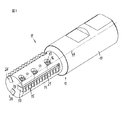
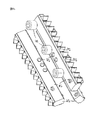
図1から4は、工具ホルダ12を有するフライス工具11を示しており、工具ホルダは直径の大きいクランプシャフト13と少し直径の小さいフライスシャフト14を有しており、このフライスシャフト内に三つの切断挿入片15が、特に、フライスシャフトのねじ孔17内へ螺合された締付けボルト16によって、挟持されている。
1 to 4 show a
切断挿入片15は、切欠き18内に配置されており、その切欠きは矩形の溝の形式に従って形成され、フライスシャフトに沿って延び、かつ工具中心軸19に対して平行に延びている。その切欠きの、切断挿入片の中心平面に対して平行に延び、かつそれとほぼ一致する、中心平面20は、半径方向かつ軸19に対して平行に延びている。
The
図4aから4cから最もよく理解される、切断挿入片15は、細長いバーの形状を有しており、そのバーは長手側に、ねじを切るために設けられている歯付きのプロフィールを備えた切断刃21を有している。切断刃は、中心平面20を中心に対称であるので、切断刃21は両側に設けられている。従って切断挿入片は、180°回すことによって二重に使用することができる。従ってまた両方の側に、適切な切削角度のためのそれに対応する斜めの切削面22とそれに連続する切削ブレーク段23が形成されている。
The cutting insert 15, best understood from FIGS. 4 a to 4 c, has the shape of an elongated bar, which on the long side is provided with a toothed profile provided for threading. A
切断挿入片は、さらに、ほぼ平坦で互いに対して平行な側面24と切断刃とは逆の終端面25およびそのバー形の端部の端面26を有している。
The cutting insert further has a
側面24の長手方向の延びの中央に、中心に対して対称かつ互いに対して距離をもって、一つの側面につきそれぞれ三つの凹部27が設けられている。その凹部は、側面の、終端面を向いた後方の稜の比較的近傍に設けられている、平坦な底を有する窪み(図3を参照)である。
In the center of the longitudinal extension of the
切断挿入片は、大体において、多くは焼結または研磨によってしか加工できない、硬質合金または他の硬質材料からなる。切断挿入片の細長いフラットなバー形状は、効率のよい形成を可能にする。 Cutting inserts are generally made of a hard alloy or other hard material that can only be processed by sintering or polishing. The elongated flat bar shape of the cutting insert allows for efficient formation.
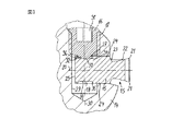
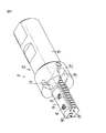
図3は、中央の締付けボルト16と切断挿入片15の断面を、挟持された状態で著しく拡大して示している。図から明らかなように、切欠き18は、切断挿入片15の厚みに適合された幅を有し、かつフライスシャフト14にほぼ半径方向に穿設されている。切断挿入片の図面下方に位置する側面24が切断挿入片の対応する面に当接し、その終端面25も切欠きの底に接している。
FIG. 3 shows the cross-sections of the
切欠きには、孔29が交差しており、その孔の孔軸30は、切欠き18と切断挿入片15の中心軸によって表される中心平面に直角である。孔29は、その開口側を向いた部分がねじ孔17として形成されており、そのねじ孔内へ締付けボルト16が螺合されている。この締付けボルトは、内側のガイド面、たとえば内側六稜を有する、頭部のない埋込みボルトである。この埋込みボルトは、切断挿入片を向いた端部に、直径の小さい突出部32を有しており、その終端面33が1つの凹部27の、特に、側面24とそれに伴って中央平面20に対して平行な底34上に載置される。
A
図から明らかなように、比較的大きくて力の強い締付けボルトを使用することができ、フライス工具の寸法がかなり小さい場合に、それが利点となる。締付けボルト16の突出部32が、凹部内で切断挿入片に作用して、この切断挿入片の、図3では下方の側面24を切欠き18の側壁へ押圧するが、中心平面20の方向の力を切断挿入片へ及ぼすことはない。突出部32の斜めの側面は、切断挿入片がきちんと挟持されている場合には、凹部の端縁35と協働しない。図4aから4cが示すように滑らかな側面24へ作用する、この締付けボルトと残りの2本の締付けボルトも緩められる場合には、中央の締付けボルト16が緩められて、突出部32が凹部から完全に抜け出すまで、凹部27を終端面25へ向かって画成する隆起部36が切断挿入片を抜け落ちないように固定している。
As is apparent from the figure, relatively large and powerful clamping bolts can be used, which is an advantage when the dimensions of the milling tool are rather small. The projection 32 of the clamping
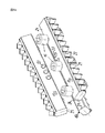
図2および図4aから4cを見るとわかるように、締付けボルト16のねじ孔17は、フライス工具11の長手方向に、従って工具中心軸19に沿って、それぞれ半径方向の平面上に、フライスシャフトを弱めるねじ孔が一つだけ設けられるように、互いに変位されている。
As can be seen in FIGS. 2 and 4a to 4c, the threaded
これを具体的に示すために、図4aから4cにおいて、互いに等しい挿入片15が添字aからcで示されている。図から明らかなように、挿入片15aにおいては、締付けボルトは最も左(ないしは前)で作用し、従って中央の締付けボルト16も最も左に位置する凹部孔27内へ嵌入し、挿入片15b(図4b)においてはそれがそれぞれ中央の位置であって、挿入片15c(図4cにおいて最もよく見える)においては、締付けボルトはそれぞれ最も右に位置する側で作用している。従ってそれぞれの変位は、凹部27の互いに対する縦の間隔に相当し、かつ好ましくは、少なくともねじ孔17の直径と等しい大きさである。
In order to illustrate this, in FIGS. 4a to 4c,
従って、内側のガイド面(内側6稜、Torxなど)を有する比較的大きくてパワーのある締付けボルトを使用できるにもかかわらず、フライスシャフトとそれに伴って全体寸法を比較的小さく形成することができることが明らかであって、従って強度的にも振動的にも著しい負荷を受けるフライスシャフトは本質的な構造的弱さをもたない。これは特に、その全直径が加工すべきねじ孔よりも小さくなければならない、内ねじをフライス加工するためのねじフライスにとって重要である。 Therefore, although a relatively large and powerful tightening bolt having an inner guide surface (inner six ridges, Torx, etc.) can be used, the milling shaft and the associated overall dimensions can be made relatively small. As such, a milling shaft that is subjected to significant loads, both strength and vibration, has no inherent structural weakness. This is particularly important for screw milling for milling internal threads, whose total diameter must be smaller than the screw hole to be machined.
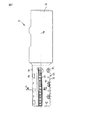
図5は、二つの切断挿入片15のみを有する形態を示している。この形成は、その他においては図1から4に示すものと同一であるが、工具ホルダ12はクランプシャフト13とフライスシャフト14の間に肥厚した部分37を有しており、その部分が切欠き38を有し、その切欠き内へクランプシャフトの一部が突出して、そこで覆われていることが、異なっている。他の部分39内には、締付けボルトのねじ孔が配置されている。この形態は、短いねじのためにも比較的長い切断挿入片15を設けて、工具全体の強度をさらに向上させるために、設けられている。
FIG. 5 shows a form having only two cutting
図6は、図5に示す工具を上面で示している。そこで図2におけるのと同様に、それぞれフライス工具11の自由端部40へ向いた前方の締付けボルトと、凹部27内へ嵌入する中央の締付けボルトの間の間隔は、終端面40から最も遠くに位置する締付けボルトへの距離よりも小さいことが、明らかである。これは、工具の自由端部40近傍における工具のより強い負荷と振動感度を考慮している。
FIG. 6 shows the tool shown in FIG. 5 on the top surface. Therefore, as in FIG. 2, the distance between the front clamping bolt that faces the
図7は、すでに図3で詳細に説明した、配置の断面を示しており、かつ、図示の平面において左に位置する切断挿入片15のための締付けボルトがないことにより、フライスシャフト断面が、変位していない配置におけるよりもずっと大きいことを、明確に示している。
FIG. 7 shows a cross-section of the arrangement already described in detail in FIG. 3 and the absence of a clamping bolt for the cutting
図面に示す、フライス工具と切断挿入片の形態および具体的説明は、特に効果的であり、図面表示は開示のためにはっきりと参照される。 The form and specific description of the milling tool and the cutting insert shown in the drawings are particularly effective and the drawing representation is explicitly referred to for disclosure.
11 フライス工具
12 工具ホルダ
13 クランプシャフト
14 フライスシャフト
15 切断挿入片
16 締付けボルト
17 ねじ孔
18 切欠き
19 工具中心軸
21 切断刃
DESCRIPTION OF
Claims (13)
Applications Claiming Priority (1)
| Application Number | Priority Date | Filing Date | Title |
|---|---|---|---|
| DE102004043409A DE102004043409A1 (en) | 2004-09-02 | 2004-09-02 | Milling tool, in particular thread milling cutter |
Publications (1)
| Publication Number | Publication Date |
|---|---|
| JP2006068898A true JP2006068898A (en) | 2006-03-16 |
Family
ID=35427930
Family Applications (1)
| Application Number | Title | Priority Date | Filing Date |
|---|---|---|---|
| JP2005255174A Pending JP2006068898A (en) | 2004-09-02 | 2005-09-02 | Milling tools, especially thread milling |
Country Status (9)
| Country | Link |
|---|---|
| US (1) | US20060045633A1 (en) |
| EP (1) | EP1640095B1 (en) |
| JP (1) | JP2006068898A (en) |
| CN (1) | CN1743112A (en) |
| AT (1) | ATE383921T1 (en) |
| DE (2) | DE102004043409A1 (en) |
| ES (1) | ES2300913T3 (en) |
| PL (1) | PL1640095T3 (en) |
| TW (1) | TW200615068A (en) |
Cited By (3)
| Publication number | Priority date | Publication date | Assignee | Title |
|---|---|---|---|---|
| JP2012040682A (en) * | 2010-08-20 | 2012-03-01 | Vargus Ltd | Thread-milling cutter and thread-milling insert |
| DE102020000155A1 (en) | 2019-01-17 | 2020-07-23 | Tungaloy Corporation | Indexable cutting tool |
| JP2021531991A (en) * | 2018-08-16 | 2021-11-25 | ハルトメタル−ウェルクゾーグファブリック ポール ホーン ゲゼルシャフト ミット ベシュレンクテル ハフツング | Thread cutting tool |
Families Citing this family (14)
| Publication number | Priority date | Publication date | Assignee | Title |
|---|---|---|---|---|
| IL192785A0 (en) * | 2007-10-22 | 2009-02-11 | Gershon Harif | Cutting tool with protrusions, and methods of use thereof |
| DE102008053772A1 (en) * | 2008-10-22 | 2010-04-29 | Komet Jel Precision Tools | thread former |
| US10201856B2 (en) | 2012-05-24 | 2019-02-12 | Gershon System Ltd. | Method for designing a cutting edge of a cutting tool, cutting tools comprising the same, and cutting elements with multiple such cutting portions |
| USD668697S1 (en) * | 2012-06-29 | 2012-10-09 | Hsu Shao-Hsien | Tool bit |
| EP3046708A1 (en) | 2013-09-17 | 2016-07-27 | Gershon System Ltd. | Cutting element and a method of cutting using the same |
| CN103639544B (en) * | 2013-11-19 | 2016-01-13 | 苏州蓝王机床工具科技有限公司 | A kind of novel indexable screw tool |
| EP2954968B1 (en) * | 2014-06-13 | 2021-01-20 | Walter Ag | Thread milling cutter |
| DE202014008275U1 (en) * | 2014-10-16 | 2014-10-27 | KARL SCHÜSSLER GmbH & Co. KG | clamping system |
| CN104439462A (en) * | 2014-11-28 | 2015-03-25 | 倪传华 | Finger-shaped rough milling cutter with wavy blades |
| DE112016002089B4 (en) * | 2015-05-08 | 2024-12-19 | Milwaukee Electric Tool Corporation | milling tool |
| CN104923811A (en) * | 2015-06-05 | 2015-09-23 | 柳州市邕达工配厂 | Lathe groove tool rod with 70 holes |
| CN105665808A (en) * | 2016-04-08 | 2016-06-15 | 朱德仲 | Milling tool with replaceable blades |
| EP3750654A1 (en) | 2019-06-14 | 2020-12-16 | VARGUS Ltd. | Thread milling cutter |
| EP4008468A1 (en) * | 2020-12-02 | 2022-06-08 | Seco Tools Ab | Thread milling tool and thread milling insert |
Citations (1)
| Publication number | Priority date | Publication date | Assignee | Title |
|---|---|---|---|---|
| JP2003503219A (en) * | 1999-06-29 | 2003-01-28 | セコ ツールズ アクティエボラーグ(プブル) | Thread milling cutter and thread milling insert |
Family Cites Families (21)
| Publication number | Priority date | Publication date | Assignee | Title |
|---|---|---|---|---|
| US1411799A (en) * | 1920-09-07 | 1922-04-04 | Miller Ralph | Milling and like cutting tool |
| US3059676A (en) * | 1959-04-06 | 1962-10-23 | Dale L Schubert | Method of flaking wood and rotary tunnel flaker therefor |
| US3574911A (en) * | 1969-12-17 | 1971-04-13 | Milling Specialties Inc | Cutter and inserts therefor |
| DE2948250A1 (en) * | 1979-11-30 | 1981-07-23 | August Beck GmbH & Co, 7472 Winterlingen | REAMER WITH A FLAT RECTANGULAR INSERT |
| DE2948544A1 (en) * | 1979-12-03 | 1981-06-11 | Sandvik GmbH, 4000 Düsseldorf | KNIFE HEAD FOR HIGH-SPEED ROLL MILLING |
| WO1982000609A1 (en) * | 1980-08-20 | 1982-03-04 | Wale D | Clamp tip tooling |
| US4400117A (en) * | 1981-05-04 | 1983-08-23 | Milling Specialties, Inc. | Insert type milling cutter |
| DE3136502A1 (en) * | 1981-09-15 | 1983-03-31 | Feldmühle AG, 4000 Düsseldorf | CUTTING TOOL |
| US4697963A (en) * | 1985-02-08 | 1987-10-06 | Ingersoll Cutting Tool Company | Insert clamping device and insert therefor |
| DE8528605U1 (en) * | 1985-10-08 | 1986-06-05 | Frey, Werner, 7432 Bad Urach | Tool consisting of holder and carbide indexable insert |
| DE3715338A1 (en) * | 1987-05-08 | 1988-11-24 | Feldmuehle Ag | FAST-ROTATING MILL OR DRILL HEAD |
| DE3838816A1 (en) * | 1988-11-17 | 1990-05-23 | Feldmuehle Ag | CUTTING TOOL FOR CUTTING MACHINING |
| US5088861A (en) * | 1990-01-23 | 1992-02-18 | Threading Systems, Inc. | Threadmilling tool |
| US5059070A (en) * | 1990-12-20 | 1991-10-22 | Gte Valenite Corporation | Two-edge threading milling insert |
| US5112162A (en) * | 1990-12-20 | 1992-05-12 | Advent Tool And Manufacturing, Inc. | Thread milling cutter assembly |
| ES2110019T3 (en) * | 1993-04-14 | 1998-02-01 | Stellram Gmbh | STRAWBERRY. |
| US5480272A (en) * | 1994-05-03 | 1996-01-02 | Power House Tool, Inc. | Chasing tap with replaceable chasers |
| DE4430171C2 (en) * | 1994-08-25 | 1996-08-14 | Walter Ag | Form-locked insert |
| US5873684A (en) * | 1997-03-29 | 1999-02-23 | Tool Flo Manufacturing, Inc. | Thread mill having multiple thread cutters |
| US5924825A (en) * | 1998-07-06 | 1999-07-20 | Caterpillar Inc. | Thread cutting insert |
| FR2816857B1 (en) * | 2000-11-20 | 2003-02-28 | Faurecia Sieges Automobile | METHOD AND DEVICE FOR SCRAPING A REINFORCEMENT TUBE FOR A MOTOR VEHICLE SEAT, IN PARTICULAR A HEADREST REINFORCEMENT TUBE |
-
2004
- 2004-09-02 DE DE102004043409A patent/DE102004043409A1/en not_active Withdrawn
-
2005
- 2005-08-25 DE DE502005002549T patent/DE502005002549D1/en not_active Expired - Lifetime
- 2005-08-25 EP EP05018463A patent/EP1640095B1/en not_active Expired - Lifetime
- 2005-08-25 PL PL05018463T patent/PL1640095T3/en unknown
- 2005-08-25 AT AT05018463T patent/ATE383921T1/en not_active IP Right Cessation
- 2005-08-25 ES ES05018463T patent/ES2300913T3/en not_active Expired - Lifetime
- 2005-08-31 US US11/216,983 patent/US20060045633A1/en not_active Abandoned
- 2005-09-02 CN CNA2005100996920A patent/CN1743112A/en active Pending
- 2005-09-02 JP JP2005255174A patent/JP2006068898A/en active Pending
- 2005-09-02 TW TW094130111A patent/TW200615068A/en unknown
Patent Citations (1)
| Publication number | Priority date | Publication date | Assignee | Title |
|---|---|---|---|---|
| JP2003503219A (en) * | 1999-06-29 | 2003-01-28 | セコ ツールズ アクティエボラーグ(プブル) | Thread milling cutter and thread milling insert |
Cited By (4)
| Publication number | Priority date | Publication date | Assignee | Title |
|---|---|---|---|---|
| JP2012040682A (en) * | 2010-08-20 | 2012-03-01 | Vargus Ltd | Thread-milling cutter and thread-milling insert |
| JP2021531991A (en) * | 2018-08-16 | 2021-11-25 | ハルトメタル−ウェルクゾーグファブリック ポール ホーン ゲゼルシャフト ミット ベシュレンクテル ハフツング | Thread cutting tool |
| DE102020000155A1 (en) | 2019-01-17 | 2020-07-23 | Tungaloy Corporation | Indexable cutting tool |
| US11413696B2 (en) | 2019-01-17 | 2022-08-16 | Tungaloy Corporation | Indexable cutting tool |
Also Published As
| Publication number | Publication date |
|---|---|
| ES2300913T3 (en) | 2008-06-16 |
| DE502005002549D1 (en) | 2008-03-06 |
| PL1640095T3 (en) | 2008-06-30 |
| CN1743112A (en) | 2006-03-08 |
| US20060045633A1 (en) | 2006-03-02 |
| EP1640095A2 (en) | 2006-03-29 |
| TW200615068A (en) | 2006-05-16 |
| EP1640095A3 (en) | 2006-05-03 |
| EP1640095B1 (en) | 2008-01-16 |
| ATE383921T1 (en) | 2008-02-15 |
| DE102004043409A1 (en) | 2006-03-09 |
Similar Documents
| Publication | Publication Date | Title |
|---|---|---|
| JP2006068898A (en) | Milling tools, especially thread milling | |
| KR101299756B1 (en) | A tool for chip removing machining as well as a basic body and a lock member therefor | |
| CN102227280B (en) | Clamping mechanism of cutting tool | |
| EP2077171B1 (en) | Cutting tool having cutting insert secured by non-penetrating abutment of a threaded fastener | |
| KR101105058B1 (en) | Cutting tool and insert for cutting tool | |
| EP1197281A1 (en) | Cutting tool with cutting inserts and method for assembling the same | |
| EP2420340B1 (en) | Thread-milling insert and thread-milling cutter | |
| RU2717617C1 (en) | Cutting plate and cutting tool | |
| US6551036B2 (en) | Drilling bit and holder for drilling bit | |
| JP2005510370A (en) | Rotary cutting tool | |
| WO2002034441A1 (en) | Rotatable tool having a replaceable cutting part at the chip removing free end of the tool | |
| JP2008155366A (en) | Rotary tool and rotary insert | |
| CN1095711C (en) | Milling tool | |
| RU2470741C2 (en) | Disc mill | |
| EP2342034A1 (en) | Cutting tool and cutting insert therefor | |
| HU222793B1 (en) | Cutting tool | |
| JP5167782B2 (en) | Ring with cutting edge | |
| KR20040058303A (en) | Rotatable cutting tool with adjustable cutting insert | |
| KR100887918B1 (en) | Rotary cutting tools and inserts for inserts | |
| US8500374B2 (en) | Cutting tool and cutting insert having clamping recess therefor | |
| US6231274B1 (en) | End mill | |
| US4137000A (en) | Cutting tool | |
| US6196774B1 (en) | Cutting insert | |
| CA3211642A1 (en) | Cutting insert and cutting tool | |
| JPH11277306A (en) | Milling tool |
Legal Events
| Date | Code | Title | Description |
|---|---|---|---|
| A621 | Written request for application examination |
Free format text: JAPANESE INTERMEDIATE CODE: A621 Effective date: 20080818 |
|
| A131 | Notification of reasons for refusal |
Free format text: JAPANESE INTERMEDIATE CODE: A131 Effective date: 20110607 |
|
| A02 | Decision of refusal |
Free format text: JAPANESE INTERMEDIATE CODE: A02 Effective date: 20111101 |