JP2006063733A - Bearing wall of high magnification - Google Patents
Bearing wall of high magnification Download PDFInfo
- Publication number
- JP2006063733A JP2006063733A JP2004250069A JP2004250069A JP2006063733A JP 2006063733 A JP2006063733 A JP 2006063733A JP 2004250069 A JP2004250069 A JP 2004250069A JP 2004250069 A JP2004250069 A JP 2004250069A JP 2006063733 A JP2006063733 A JP 2006063733A
- Authority
- JP
- Japan
- Prior art keywords
- bearing wall
- vertical frame
- frame
- face material
- wall
- Prior art date
- Legal status (The legal status is an assumption and is not a legal conclusion. Google has not performed a legal analysis and makes no representation as to the accuracy of the status listed.)
- Pending
Links
Images


Abstract
Description
本発明は、大きな水平耐力を有した枠組壁工法における耐力壁に関する。 The present invention relates to a load bearing wall in a frame wall construction method having a large horizontal strength.
枠組壁工法において、外力に抵抗するための耐力壁101として、左右に垂直に立設された縦枠とこの縦枠の上下端に横設された横枠とにより構成された枠部材110に、その一方の断面に構造用合板等の構造用面材120が直接釘130などにより張りつけられたものがある(図6(a)参照)。
このように、構成することにより、耐力壁101は3.0倍程度の壁倍率を得ることを可能としている。
In the frame wall construction method, as the load-bearing
By configuring in this way, the
前記の施工方法による耐力壁101は、枠部材110に構造用面材120を直接釘打ち等により固定するものであり、その強度は、釘130の耐力によるものである。つまり、釘130の一面せん断耐力により耐力壁101の耐力が決定されていた。
The
そのため、従来、前記の壁倍率(3.0倍)以上の耐力を得るためには、構造用面材120の釘打ち間隔を狭める方法がとられていた。
また、特許文献1には、耐力壁の壁倍率を上げるために、図6(b)に示すように、構造用面材120の周囲に金属製又は合成樹脂等で構成した薄い保持力テープ140を介在して、その上から枠構造110に釘130により固定することにより、釘130の頭部が保持力テープ140を介して広い面で構造用面材120を止着することで壁倍率を3.5倍程度まで増加させることを可能とした耐力壁が記載されている。
Further, in Patent Document 1, in order to increase the wall magnification of the bearing wall, as shown in FIG. 6B, a thin
ところが、前者の釘打ち間隔を狭める方法は、壁倍率は上昇するものの、耐力壁の靱性が低下するという問題点を有していた。そのため、例えば保有水平耐力の確認の際には、終局時の建物の安全性を考慮して地震力によって各階に生じる水平力を割増して計算する必要があった。
また、後者の保持力テープを介在する方法も、ある程度の壁倍率の増加は見込めるものの、釘の一面せん断力による耐力に頼るため、壁倍率の増加には限界があるという問題点を有していた。
However, the former method of narrowing the nailing interval has a problem that the toughness of the bearing wall is lowered, although the wall magnification is increased. For this reason, for example, when checking the retained horizontal proof stress, it is necessary to take into account the safety of the building at the end of the event and to calculate by increasing the horizontal force generated on each floor by the seismic force.
In addition, the latter method of interposing the holding force tape is expected to increase the wall magnification to some extent, but has the problem that there is a limit to the increase in the wall magnification because it depends on the proof strength due to the shearing force of one surface of the nail. It was.
本発明は、前記の問題点を解決するためになされたものであり、枠組壁工法における耐力壁の高壁倍率化とそれに伴う靱性低下の防止を可能とする、高倍率の耐力壁を提案することを課題とする。 The present invention has been made in order to solve the above-mentioned problems, and proposes a high-magnification bearing wall that makes it possible to increase the magnification of the bearing wall in the frame wall construction method and to prevent toughness deterioration associated therewith. This is the issue.
このような課題を解決するために、請求項1に記載の発明は、所定の間隔で立設された縦枠と前記縦枠の上下端部に横設される横枠とからなる枠部材と、構造用面材とを主体とする高倍率の耐力壁であって、前記縦枠は、前記構造用面材の前後に配設されており、前記構造用面材と、固定部材を介して固定されていることを特徴としている。 In order to solve such a problem, the invention according to claim 1 is a frame member comprising a vertical frame erected at a predetermined interval and a horizontal frame horizontally disposed at the upper and lower ends of the vertical frame. , A high-magnification bearing wall mainly composed of a structural surface material, wherein the vertical frame is disposed before and after the structural surface material, and the structural surface material and a fixing member It is characterized by being fixed.
また、請求項2に記載の発明は、請求項1に記載の高倍率の耐力壁であって、前記縦枠と前記構造用面材とは、前記固定部材を介して二面せん断接合により固定されていることを特徴としている。
The invention according to
かかる高倍率の耐力壁は、構造用面材がその前後の縦枠により釘やビス等の固定部材を介して固定されているため、固定部材による二面せん断接合がなされている。そのため、従来の一面せん断接合の耐力壁に比べて優れたせん断耐力を発現することを可能としている。また、従来と同じ釘打ち間隔、あるいは従来よりも広い釘打ち間隔で、優れたせん断耐力を発現することができる。そのため、固定部材の間隔や打ちしろに余裕があるため、施工品質が確保しやすく、靱性が低下することもない。また、壁倍率が向上することから、建物の設計において必要となる耐力壁長さの低減が可能となり、経済的な建物の構築が可能となるとともに、窓や出入り口の配置等の設計の自由度が増す。 Such a high-strength load-bearing wall is formed by two-surface shear bonding by a fixing member because the structural face material is fixed by a vertical frame before and after the fixing member through a fixing member such as a nail or a screw. Therefore, it is possible to exhibit a superior shear strength as compared with the conventional load-bearing wall of single-surface shear bonding. In addition, an excellent shear strength can be exhibited at the same nail interval as before or at a wider nail interval than before. For this reason, since there is a margin in the interval between the fixing members and the margin to be hit, it is easy to ensure the construction quality and the toughness does not deteriorate. In addition, since the wall magnification is improved, it is possible to reduce the length of the load-bearing wall required for building design, and it is possible to construct an economical building, and the degree of freedom in designing the layout of windows and doorways. Increase.
また、前記構造用面材が、前記横枠の内側面に固定された補足材に固定されることにより、前記横枠と固定されれば、作業が簡易なため高倍率の耐力壁の構築が容易となり、好適である。 In addition, since the structural face material is fixed to a supplementary material fixed to the inner side surface of the horizontal frame, if it is fixed to the horizontal frame, construction of a high-magnification load-bearing wall is simple because the work is simple. It is easy and suitable.
また、前記枠部材の一方又は両方の面に構造用面材が取り付けられていれば、高倍率の耐力壁の耐力をさらに高めることが可能となり、好適である。 Further, if a structural face material is attached to one or both surfaces of the frame member, it is possible to further increase the proof stress of the high-magnification bearing wall.
本発明の高倍率の耐力壁により、枠組壁工法の耐力壁について、靱性を低下させずに高壁倍率化が可能となった。 With the high-strength load-bearing wall of the present invention, it is possible to increase the wall-strength without reducing the toughness of the load-bearing wall of the frame wall construction method.
以下、本発明の好適な実施の形態について、図面を参照して説明する。なお、説明において、同一要素には同一の符号を用い、重複する説明は省略する。
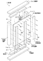
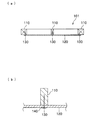
図1は、本実施の形態にかかる高倍率の耐力壁(以下、単に「耐力壁」という場合がある)の斜視図である。また、図2は、図1の耐力壁1の断面図を示しており、(a)は図1に示すA−A断面、(b)は同B−B断面、(c)は図2(a)のC部分の拡大断面図である。なお、説明において、「内側」「外側」は、請求項1の「前」「後」に対応しており、耐力壁1を設置した状態で決定するものとし、図1で示す方向に統一する。
DESCRIPTION OF EXEMPLARY EMBODIMENTS Hereinafter, preferred embodiments of the invention will be described with reference to the drawings. In the description, the same reference numerals are used for the same elements, and duplicate descriptions are omitted.
FIG. 1 is a perspective view of a high-magnification bearing wall (hereinafter sometimes simply referred to as “bearing wall”) according to the present embodiment. 2 shows a cross-sectional view of the load-bearing wall 1 of FIG. 1. FIG. 2A is a cross-sectional view taken along the line AA shown in FIG. 1, FIG. 2B is a cross-sectional view taken along the line BB, and FIG. It is an expanded sectional view of C part of a). In the description, “inner side” and “outer side” correspond to “front” and “rear” of claim 1 and are determined in a state where the bearing wall 1 is installed, and are unified in the direction shown in FIG. .
図1に示すように、耐力壁1は、所定の間隔で立設された縦枠11とこれらの縦枠11の上下端部に横設される横枠12とからなる枠部材10と、構造用面材20を主体としている。
As shown in FIG. 1, the load-bearing wall 1 includes a
構造用面材20は、その厚みが12mmの構造用合板からなり、その内側と外側に対となるように設けられた縦枠11と、釘30を介して固定されている。そして、この構造用面材20及び縦枠11と、その上下に配置された横枠12とを固定することにより耐力壁1が形成されている。ここで、構造用面材20として構造用合板を使用するものとしたが、これに限定されるものではなく、公知の面材から状況に応じて適宜選定すればよい。また、構造用合板の厚みは、状況に応じて適宜設定すればよく、12mmに限定されるものではない。
The
そして、耐力壁1は、アンカー4を介して基礎3に固定された土台2に、この土台2と内外の縦枠11とにまたがって配設されたT字金物からなる取付金具40によりその下部が固定されている。そして、耐力壁1の上部は、図示しない天井根太又は上層階の床根太と内外の縦枠11とにまたがって配設された取付金具40により固定されている。なお、2階部分以上に配設される耐力壁11の下部は、内外の縦枠11と床根太にまたがって配設される取付金具により固定されている。ここで、本実施の形態では、T字金物からなる取付金具40を介して耐力壁1を土台2や根太に固定する構成としたが、耐力壁1の固定方法は限定されるものではなく、例えばホールダウン金物、V字金物、L字金物等を利用するなど、公知の方法から適宜選定して行えばよい。また、特に2階部分以上の耐力壁1に関しては、帯金物により、下層階の耐力壁1と接合する構成としてもよい。
The bearing wall 1 is mounted on a
本実施形態では、1組の耐力壁1に対して、図2(a)に示すように、構造用面材20の両端部に配設される外端部縦枠11a,11aと両外端部縦枠11a,11aの中央に配設される外中央縦枠11bと、構造用面材20の内側の両外端部縦枠11a,11aに対応する位置に配設された内端部縦枠11c,11cと外中央縦枠11bに対応する位置に配設される内中央縦枠11dとの合計6本の縦枠11を有している。
In the present embodiment, as shown in FIG. 2A, the outer end
本実施の形態では、外端部縦枠11a,11aと外中央縦枠11bとして、いわゆる2×4材(通常、断面の幅が38mm、高さが89mm)を使用するものとし、その断面において広い方の一辺が構造用面材20に当接するように配置されている。また、内端部縦枠11c,11cには、いわゆる4×4材(通常、断面の幅,高さ共に89mm)を使用するものとし、その一辺が構造用面材20に当接するように配置されている。さらに、内中央縦枠11dには、外端部縦枠11a,11aと外中央縦枠11bと同様に、2×4材を使用するものとして、その断面において狭い方の一辺が構造用面材20に当接するように配置されている。
In the present embodiment, as the outer end
そして、外端部縦枠11a,11aと内端部縦枠11c,11c及び外中央縦枠11bと内中央縦枠11dにより、構造用面材20をその内外から挟み、外側から釘30を打込むことで固定されている。ここで、釘30は、外端部縦枠11a,11a及び外中央縦枠11bと構造用面材20を貫通し、内端部縦枠11c,11c及び内中央縦枠11dに所定の定着長が確保できる程度の長さを有しているものを使用する(図2(c)参照)。
Then, the
横枠12には、いわゆる2×6材(通常、断面の幅が39mm、高さが140mm)を使用するものとし、図2(b)に示すように、その断面において広い方の一辺が縦枠11の上下端部及び構造用面材20の上下端部に当接するように配置されている。上側横枠12aの下面(請求項3の内側面に対応)と下側横枠12bの上面(請求項3の内側面に対応)には、構造用面材20よりも内側で、かつ、内端部縦枠11c,11cと内中央縦枠11dとの間に、それぞれ2×4材からなる補足材13が配設されている。各補足材13,13,…は、その断面において広い方の一辺が上側横枠12aの下面又は下側横枠12bの上面に当接した状態で釘31により固定されている。
そして、構造用面材20の内側面の上下端部が各補足材13,13,…に当接するように配置された後、外側から釘32を打込むことにより、構造用面材20と横枠12との固定がなされる。
As the
After the upper and lower ends of the inner side surface of the
次に、図3を参照して、本実施の形態に係る耐力壁1の構築方法について説明する。 Next, with reference to FIG. 3, the construction method of the bearing wall 1 which concerns on this Embodiment is demonstrated.
まず、構造用面材20の左右端部に、その内側及び外側から、構造用面材20の高さと同じ長さの外端部縦枠11a及び内端部縦枠11cを、構造用面材20を挟んだ状態で配置する。そして、外端部縦枠11aの外側面から、内端部縦枠11cに所定の定着長が確保できるように、等間隔で釘30を打込み、外端部縦枠11a及び内端部縦枠11cと構造用面材20とを固定する。また、これとともに、構造用面材20の中央に、その内側及び外側から、構造用面材20の高さと同じ長さの外中央縦枠11b及び内中央縦枠11dを、構造用面材20を挟んだ状態で配置する。そして、外中央縦枠11bの外側面から、内中央縦枠11dに所定の定着長が確保できるように、等間隔で釘30を打込み、外中央縦枠11a及び内中央縦枠11cと構造用面材20とを固定する。
First, the outer end
ここで、縦枠11の構造用面材20への固定について、釘30を外端部縦枠11aや外中央縦枠11bから打込む構成としたが、例えば内端部縦枠11cや内中央縦枠11dから打込む構成や、内側と外側との両方向から打込む構成としてもよく、縦枠11と構造用面材20との固定が可能であれば、その打込む方向は限定されるものではない。
Here, for fixing the
次に、縦枠11が固定された構造用面材20の上端に上側横枠12a、下端に下側横枠12bを配置する。上側横枠12aの下面及び下側横枠12bの上面には、補足材13が、縦枠11が配置される位置をよけて、釘31により固定されている。
Next, the upper
そして、構造用面材20の外側から、上下の補足材13に対応する位置に釘32を打込むことにより、上側横枠12a及び下側横枠12bと構造用面材20との固定を行い、耐力壁1を構築する。なお、補足材13は、上側横枠12aと下側横枠12bを構造用面材20の上下端に配置した後、構造用面材20と両横枠12,12との接合部の所定の位置に配置して、構造用面材20と横枠12に釘31,32により固定してもよい。
Then, the
以上のように、本発明による耐力壁1は、図2(c)に示すように、構造用面材20と、その内側と外側に配置された縦枠11とを、1本の釘30を介して固定するため、いわゆる二面せん断接合であり、釘30によるせん断耐力が通常の耐力壁(図6参照)の釘のせん断耐力に比べて約2倍となるため、優れた耐力を有した耐力壁が構築される。
As described above, the load-bearing wall 1 according to the present invention includes the
また、本実施形態に係る耐力壁1は、内側と外側の縦枠11,11と構造用面材20との組み合わせにより、通常の2×6材の高さと略同じ厚みを有しているため、図4に示すように、通常の2×6材を縦枠51として起用する一般壁50との連結も、一般壁の外側構造用面材52と同様の厚みを有した外側構造用面材21を設置することにより、容易に行うことが可能となる。
In addition, the bearing wall 1 according to the present embodiment has substantially the same thickness as the height of a normal 2 × 6 material due to the combination of the inner and outer
また、図4に示すように、耐力壁1の外側面に、さらに他の構造用面材(外側構造用面材)21を、釘を介して一面せん断接合すれば、さらに、耐力壁1の壁倍率を高めることが可能となる。 In addition, as shown in FIG. 4, if another structural surface material (outer structural surface material) 21 is further shear-bonded to the outer surface of the load-bearing wall 1 through a nail, the load-bearing wall 1 is further bonded. The wall magnification can be increased.
また、本発明の高倍率の耐力壁により、耐力壁の高壁倍率化、およびそれに伴う靱性低下の防止が実現されるため、下記に示す効果を得ることが可能となる。
(1)建物の設計において耐力壁長さの低減が可能となるため、建物の壁の開口部設置など、設計の自由度が増す。
(2)内壁に頼らない外壁だけによる水平力の負担が容易になり、設計の自由度が拡大する。
(3)木造耐火構造、混構造(例えば、RC構造と2×4構造との混合構造の建物等)など、固定荷重が重い建物の構築に有利である。
(4)釘の打ちしろ拡大による施工性及び施工品質の向上。
In addition, since the high-strength load-bearing wall according to the present invention can realize a higher wall-strength of the load-bearing wall and prevent the accompanying toughness reduction, the following effects can be obtained.
(1) Since the bearing wall length can be reduced in the design of the building, the degree of freedom in design such as the installation of an opening in the building wall is increased.
(2) The burden of horizontal force only by the outer wall that does not depend on the inner wall becomes easy, and the degree of freedom in design is expanded.
(3) It is advantageous for construction of a building having a heavy fixed load, such as a wooden fireproof structure and a mixed structure (for example, a building having a mixed structure of RC structure and 2 × 4 structure).
(4) Improvement of workability and construction quality by expanding the nails.
以下、本発明に係る耐力壁の実証実験の結果について記載する。 Hereinafter, the result of the demonstration experiment of the bearing wall according to the present invention will be described.
表1は、釘間隔を狭めた従来の耐力壁に対して、水平力を加えて、その壁倍率を測定した結果である。なお、表1において、面材の片面貼りとは、枠部材に対して外側のみに構造用面材を設置した場合を示し、両面貼りとは、枠部材の内側と外側との両面に構造用面材を設置した構成を示している。 Table 1 shows the result of measuring the wall magnification by applying a horizontal force to a conventional bearing wall with a narrow nail interval. In Table 1, the single-sided attachment of the face material indicates a case where the structural face material is installed only on the outside of the frame member, and the double-sided attachment is for structural use on both the inside and the outside of the frame member. The structure which installed the face material is shown.

表1に示すように、耐力壁は、釘間隔を50mm(通常100mm)に狭めることにより、壁倍率(通常3.0)が片面張りで5.1となり、大幅に増加する結果が得られた。ところが、釘間隔を狭めた結果、片面貼り、両面貼り共に、靱性率μが減少するので、構造特性係数Dsが0.3以上となるため、靱性が低下することを示している。
ここで、構造特性係数Dsとは、靱性率μから求められる変形能力による地震エネルギーの吸収力に応じた低減係数であり、その数値が大きい程、大変形時における水平耐力の低下が著しいことを示している。なお、釘間隔を100mmとした通常の耐力壁では構造特性係数Ds=0.3とされている。
As shown in Table 1, with the bearing wall, the wall magnification (usually 3.0) became 5.1 on one side by narrowing the nail interval to 50 mm (usually 100 mm), resulting in a significant increase. . However, as a result of narrowing the nail interval, the toughness ratio μ decreases for both single-sided and double-sided attachments, and the structural characteristic coefficient Ds becomes 0.3 or more, indicating that the toughness decreases.
Here, the structural characteristic coefficient Ds is a reduction coefficient corresponding to the seismic energy absorption capacity due to the deformation capacity obtained from the toughness ratio μ, and the larger the value, the more significant the horizontal yield strength decreases during large deformation. Show. Note that the structural characteristic coefficient Ds = 0.3 is set for a normal bearing wall having a nail interval of 100 mm.
表2は、本発明の高倍率の耐力壁に対して、正負繰り返し水平力を加えてその壁倍率を測定した結果である。 Table 2 shows the results of measuring the wall magnification by applying positive and negative horizontal forces to the high-magnification bearing wall of the present invention.
表2より、本発明の高倍率の耐力壁は、釘間隔が200mmで、壁倍率αが7.59となり、大幅に増加する結果となった。また、構造特性係数Dsも0.28であるため、0.3以下で、大変形時の靱性低下の防止が実現されている。 Table 2 shows that the high-magnification bearing wall of the present invention has a nail interval of 200 mm and a wall magnification α of 7.59, which is significantly increased. Moreover, since the structural characteristic coefficient Ds is also 0.28, it is 0.3 or less, and the prevention of toughness reduction during large deformation is realized.
したがって、本発明の高倍率の耐力壁の外側面に、さらに構造用面材を設置すれば、壁倍率がさらに増加することが想定され、好適である(図4参照)。 Therefore, if a structural face material is further provided on the outer surface of the high-magnification bearing wall of the present invention, it is assumed that the wall magnification is further increased (see FIG. 4).
以上、本発明について、好適な実施形態について説明したが、本発明は前記各実施形態に限られず、本発明の趣旨を逸脱しない範囲で適宜設計変更が可能である。
例えば、前記実施形態では、内端部縦枠11cとして4×4材、内中央縦枠11dとして2×4材を使用するものとしたが、縦枠の材料はこれに限定されるものではなく、例えば、図5に示すように、内端部外枠11c’及び内中央縦枠11d’として2×2材を使用して、耐力壁1’の厚みを2×2材の高さと同等とすることで、2×2材を使用した一般壁との接合を可能とする構成としてもよい。
As mentioned above, although preferred embodiment was described about this invention, this invention is not limited to said each embodiment, A design change is possible suitably in the range which does not deviate from the meaning of this invention.
For example, in the above-described embodiment, 4 × 4 material is used as the inner end
また、前記実施形態では、一組の耐力壁において、構造用面材の内側と外側にそれぞれ3本ずつ縦枠を配置する構成としたが、例えば中央の縦枠を省略して構造用面材の内側と外側にそれぞれ2本ずつの縦枠を配置する構成や、中央の縦枠を2本ずつ配置して構造用面材の内側と外側にそれぞれ4本ずつの縦枠を配置する構成としてもよく、耐力壁の枠材の構成は限定されるものではない。 Moreover, in the said embodiment, although it was set as the structure which arrange | positions 3 vertical frames in each inside and outside of a structural surface material in a set of load bearing walls, for example, a structural surface material is omitted by omitting the central vertical frame A configuration in which two vertical frames are arranged on the inside and the outside of the frame, and a configuration in which two vertical frames are arranged on the center and four vertical frames are arranged on the inside and outside of the structural face material, respectively. The structure of the frame material of the bearing wall is not limited.
また、前記実施形態では、補足材を構造用面材の内側に配置するものとしたが、これに限定されるものではなく、構造用面材の外側、あるいは、構造用面材の内側と外側に配置してもよい。
また、前記実施形態では、固定部材として釘を使用するものとしたが、例えばビスを使用するなど、縦枠と構造用面材との二面せん断接合を可能とする部材であれば、その材料は限定されるものではない。
Moreover, in the said embodiment, although the supplementary material shall be arrange | positioned inside a structural surface material, it is not limited to this, The outer side of a structural surface material, or the inner side and outer side of a structural surface material You may arrange in.
Moreover, in the said embodiment, although the nail was used as a fixing member, if it is a member which enables the two-plane shear joining of a vertical frame and a structural surface material, such as using a screw, for example, the material Is not limited.
1 耐力壁(高倍率の耐力壁)
10 枠部材
11 縦枠
11a 外端部縦枠
11b 外中央縦枠
11c 内端部縦枠
11d 内中央縦枠
12 横枠
12a 上側横枠
12b 下側横枠
13 補足材
20 構造用面材
21 外側構造用面材(構造用面材)
1 Bearing wall (High magnification bearing wall)
DESCRIPTION OF
Claims (4)
前記縦枠は、前記構造用面材の前後に配設されており、前記構造用面材と、固定部材を介して固定されていることを特徴とする高倍率の耐力壁。 A high-strength load-bearing wall mainly composed of a vertical frame erected at a predetermined interval and a horizontal frame horizontally disposed on the upper and lower ends of the vertical frame, and a structural face material. ,
The high-strength load-bearing wall, wherein the vertical frame is disposed before and after the structural face material, and is fixed to the structural face material via a fixing member.
Priority Applications (1)
| Application Number | Priority Date | Filing Date | Title |
|---|---|---|---|
| JP2004250069A JP2006063733A (en) | 2004-08-30 | 2004-08-30 | Bearing wall of high magnification |
Applications Claiming Priority (1)
| Application Number | Priority Date | Filing Date | Title |
|---|---|---|---|
| JP2004250069A JP2006063733A (en) | 2004-08-30 | 2004-08-30 | Bearing wall of high magnification |
Publications (1)
| Publication Number | Publication Date |
|---|---|
| JP2006063733A true JP2006063733A (en) | 2006-03-09 |
Family
ID=36110449
Family Applications (1)
| Application Number | Title | Priority Date | Filing Date |
|---|---|---|---|
| JP2004250069A Pending JP2006063733A (en) | 2004-08-30 | 2004-08-30 | Bearing wall of high magnification |
Country Status (1)
| Country | Link |
|---|---|
| JP (1) | JP2006063733A (en) |
Cited By (4)
| Publication number | Priority date | Publication date | Assignee | Title |
|---|---|---|---|---|
| JP2009002008A (en) * | 2007-06-20 | 2009-01-08 | Misawa Homes Co Ltd | Installation structure for large-sized wall panel |
| CN104695594A (en) * | 2015-02-27 | 2015-06-10 | 同济大学 | Superimposed shear wall based on semi-prefabricated super-tough reinforced concrete |
| JP2015121047A (en) * | 2013-12-24 | 2015-07-02 | 積水ハウス株式会社 | Bearing wall |
| JP2017110460A (en) * | 2015-12-18 | 2017-06-22 | 原田木材株式会社 | Bearing wall structure |
Citations (3)
| Publication number | Priority date | Publication date | Assignee | Title |
|---|---|---|---|---|
| JPH09250192A (en) * | 1996-03-15 | 1997-09-22 | Mitsuo Nakayama | Double-bearing wall method of building |
| JP2000257191A (en) * | 1999-03-10 | 2000-09-19 | Nkk Corp | Bearing wall member and bearing wall for steel house |
| JP2001090184A (en) * | 1999-09-21 | 2001-04-03 | Daiken Trade & Ind Co Ltd | Wall structure for wooden building and construction method therefor |
-
2004
- 2004-08-30 JP JP2004250069A patent/JP2006063733A/en active Pending
Patent Citations (3)
| Publication number | Priority date | Publication date | Assignee | Title |
|---|---|---|---|---|
| JPH09250192A (en) * | 1996-03-15 | 1997-09-22 | Mitsuo Nakayama | Double-bearing wall method of building |
| JP2000257191A (en) * | 1999-03-10 | 2000-09-19 | Nkk Corp | Bearing wall member and bearing wall for steel house |
| JP2001090184A (en) * | 1999-09-21 | 2001-04-03 | Daiken Trade & Ind Co Ltd | Wall structure for wooden building and construction method therefor |
Cited By (4)
| Publication number | Priority date | Publication date | Assignee | Title |
|---|---|---|---|---|
| JP2009002008A (en) * | 2007-06-20 | 2009-01-08 | Misawa Homes Co Ltd | Installation structure for large-sized wall panel |
| JP2015121047A (en) * | 2013-12-24 | 2015-07-02 | 積水ハウス株式会社 | Bearing wall |
| CN104695594A (en) * | 2015-02-27 | 2015-06-10 | 同济大学 | Superimposed shear wall based on semi-prefabricated super-tough reinforced concrete |
| JP2017110460A (en) * | 2015-12-18 | 2017-06-22 | 原田木材株式会社 | Bearing wall structure |
Similar Documents
| Publication | Publication Date | Title |
|---|---|---|
| JP2007303070A (en) | Wall reinforcing structure | |
| JP3759409B2 (en) | Seismic structure and seismic connection tool | |
| JP2006063733A (en) | Bearing wall of high magnification | |
| JP3209111U (en) | Vertical frame material and steel house | |
| JP2008308820A (en) | Bearing wall structure of conventional framework wooden building | |
| WO2006057095A1 (en) | Structure of opened wall in steel house | |
| JP5974781B2 (en) | Bearing wall of wooden house | |
| JP3883970B2 (en) | Shaft structure | |
| JP2004162485A (en) | Composite panel structure | |
| JP2012122276A (en) | Damping structure and building | |
| JP2005054353A (en) | Reinforcing structure for wall having opening therein, for steel frame house | |
| JP3453523B2 (en) | Seismic structure of wooden building | |
| JP2006299609A (en) | Reinforcing structure of through-column | |
| JPH10338968A (en) | Joint metal for woody framework member | |
| JP2000104342A (en) | Load bearing structure of wooden building | |
| AU2015213539A1 (en) | Attachment components for securing portions of a structure with integrated insulation to one another | |
| JP2004308259A (en) | Metal fixture of extrusion molding cement plate and mounting method | |
| JP2005179981A (en) | Earthquake control construction of structure | |
| JP2013130054A (en) | Panel, junction structure, and wooden building using them | |
| JP2021070937A (en) | Inner wall fixing member | |
| JP2006104774A (en) | Building member connection structure | |
| JP2000320006A (en) | Joining structure of unit building | |
| JP2005232797A (en) | Column and beam mounting structure for wooden building | |
| JPH07259216A (en) | Wall surface structural body and building with its structural body | |
| JP2005146718A (en) | Wooden framework construction method using screw fastening of pinching metal fitting |
Legal Events
| Date | Code | Title | Description |
|---|---|---|---|
| A621 | Written request for application examination |
Free format text: JAPANESE INTERMEDIATE CODE: A621 Effective date: 20060526 |
|
| A977 | Report on retrieval |
Free format text: JAPANESE INTERMEDIATE CODE: A971007 Effective date: 20080130 |
|
| A131 | Notification of reasons for refusal |
Free format text: JAPANESE INTERMEDIATE CODE: A131 Effective date: 20080930 |
|
| A02 | Decision of refusal |
Free format text: JAPANESE INTERMEDIATE CODE: A02 Effective date: 20090303 |