JP2006058367A - Optical equipment - Google Patents
Optical equipment Download PDFInfo
- Publication number
- JP2006058367A JP2006058367A JP2004237298A JP2004237298A JP2006058367A JP 2006058367 A JP2006058367 A JP 2006058367A JP 2004237298 A JP2004237298 A JP 2004237298A JP 2004237298 A JP2004237298 A JP 2004237298A JP 2006058367 A JP2006058367 A JP 2006058367A
- Authority
- JP
- Japan
- Prior art keywords
- focus
- display
- ring
- distance
- lens
- Prior art date
- Legal status (The legal status is an assumption and is not a legal conclusion. Google has not performed a legal analysis and makes no representation as to the accuracy of the status listed.)
- Withdrawn
Links
Images


Abstract
Description
従来から、変倍レンズと、変倍レンズより像面側に配置され変倍レンズの移動に伴う像面変動の補正(コンペンセータの機能)およびフォーカスを行うフォーカスレンズを有するいわゆるリアフォーカス(インナーフォーカス)ズームレンズを用いたレンズ交換が可能なあるいはレンズを一体に有するデジタルカメラやビデオカメラなどの撮像装置が知られている。 Conventionally, a so-called rear focus (inner focus) having a zoom lens and a focus lens that is arranged on the image plane side of the zoom lens and corrects the image plane variation (compensator function) and moves as the zoom lens moves. An imaging device such as a digital camera or a video camera capable of exchanging a lens using a zoom lens or having a lens integrally is known.
上述のリアフォーカスズームレンズを用いた撮像装置では、カメラ側からのフォーカス駆動信号によりフォーカスレンズが駆動されてフォーカス調整が行われる。またカメラ側のズームスイッチの操作により生じるズーム駆動信号により変倍レンズが駆動されるとともに、変倍に伴う像面変動を補正するようにフォーカスレンズが駆動されてズームが行われる。 In the above-described imaging device using the rear focus zoom lens, the focus lens is driven by a focus drive signal from the camera side to perform focus adjustment. In addition, the zoom lens is driven by a zoom drive signal generated by the operation of the zoom switch on the camera side, and the focus lens is driven to perform zooming so as to correct image plane fluctuations accompanying zooming.
ここで、撮影操作を向上させるために、フォーカス調整やズーム操作を手動操作にて行う構成の撮像装置が提案されている。 Here, in order to improve the shooting operation, an imaging apparatus configured to manually perform focus adjustment and zoom operation has been proposed.
上述したリアフォーカスズームタイプの光学系を用い、マニュアルフォーカス調整を可能とした構成の撮像装置として、マニュアルフォーカスリングの回転操作に応じて、フォーカスレンズをモータにより駆動して移動させ、またオートフォーカス動作のフォーカスレンズの移動時に、マニュアルフォーカスリングをモータにより回転させる構成の撮像装置の開示がある(特許文献1参照)。この特許文献1では、マニュアルフォーカスリングの外周に距離表示の印刷を施し、固定部に指標を設けて、被写体までの距離表示を行うことも開示されている。 As an imaging device that uses the above-mentioned rear focus zoom type optical system and allows manual focus adjustment, the focus lens is driven by a motor and moved according to the rotation operation of the manual focus ring. There is a disclosure of an imaging apparatus configured to rotate a manual focus ring by a motor when the focus lens is moved (see Patent Document 1). This Patent Document 1 also discloses that distance display is printed on the outer periphery of the manual focus ring, and an index is provided on the fixed portion to display the distance to the subject.
また、上述したリアフォーカスズームタイプの光学系においては、撮影レンズのバリエータ位置(すなわち、焦点距離)に応じて、同じフォーカスレンズ位置であっても、焦点の合う被写体距離が異なることが知られている。このため、これらのズームタイプを撮影レンズとして応用しているビデオカメラ塔の撮影機器においては、一般的に、撮影可能な最至近被写体距離が、焦点距離が短いほど近い距離に設定されている(特許文献2参照)。
しかしながら、従来の特許文献1で記載された技術においては、マニュアルフォーカスリング機構に距離表示が設けられているために、その距離表示がリングの至近距離側の回転端において、全ての焦点距離において共通に焦点を合わせることが可能な最至近距離(例えば参考文献2の図13では80cm)とした場合には、特に短焦点側での撮影可能最至近距離が、ズームレンズタイプからはより近い距離の撮影が可能であるのに、特にワイド端ではほぼレンズ直前被写体へのピント合わせが可能であるのに、全焦点距離において共通に焦点を合わせることが可能な最至近距離より近距離への焦点合わせができないという課題を残している。 However, in the technique described in the conventional patent document 1, since the distance display is provided in the manual focus ring mechanism, the distance display is common to all focal lengths at the rotation end on the closest distance side of the ring. In the case of the shortest distance that can be focused on (for example, 80 cm in FIG. 13 of Reference 2), the shortest focusable distance is particularly close to the zoom lens type. Although it is possible to shoot, especially at the wide end, it is possible to focus on the subject just before the lens. The problem that cannot be done is left.
また、この点に鑑み、フォーカスリング機構の至近距離側回転端における距離表示を、ワイド側で焦点合わせが可能な距離(例えば参考文献2の図13では0cm)とした場合には、ミドルからテレ側の領域で、表示された位置にマニュアルフォーカスリングを設定しても、その距離の被写体に焦点を合わせることができないという課題を残している。 In view of this point, when the distance display at the close end of the focus ring mechanism is set to a distance that can be focused on the wide side (for example, 0 cm in FIG. 13 of Reference 2), the middle to telephoto Even if the manual focus ring is set at the displayed position in the area on the side, there remains a problem that the subject at that distance cannot be focused.
さらに、オートフォーカス動作時のフォーカスレンズの動作は、これらのレンズを用いるテレビAF方式のオートフォーカスで用いられるウォブリング(レンズを光軸方向に振動させる動作)動作などの微細で高速な動作を含み、これらの動作に、マニュアルフォーカスリングをいちいち追従させようとしても、追従遅れが発生するうえ、オートフォーカス動作時に、マニュアルフォーカスリングを操作者が抑えている場合にも、追従ができないといった課題も残している。 Furthermore, the operation of the focus lens during autofocus operation includes fine and high-speed operations such as wobbling (operation that vibrates the lens in the direction of the optical axis) that is used in TV AF autofocus using these lenses. Even if you try to make the manual focus ring follow each of these actions, there will be a follow-up delay, and there will be a problem that even if the operator is holding down the manual focus ring during autofocus operation, it will not be possible to follow. Yes.
本発明は、可動レンズの移動と外部操作される操作部材の移動との対応関係を維持することができ、操作性の向上を図ることのできる光学機器を提供するものである。 The present invention provides an optical apparatus that can maintain the correspondence between the movement of a movable lens and the movement of an operation member that is externally operated, and can improve operability.
本発明の第1形態の光学機器は、合焦距離が表示され、メカ的に可動範囲が規制された第1の表示部材と、エンドレスに操作可能な操作部材と、上記表示部材の可動範囲内の絶対位置を検出する表示部材位置検出手段と、上記操作部材の操作に関する情報を検出するリング操作検出手段と、前記表示部材を駆動する表示部材駆動源と、焦点距離検出手段と、制御手段と、を有し、前記制御手段は焦点距離に応じて、前記表示部材の至近側の可動範囲端を、前記メカ的な規制範囲より内側で可変設定することを特徴とする。 An optical apparatus according to a first aspect of the present invention includes a first display member that displays a focusing distance and whose movable range is mechanically restricted, an operation member that can be operated endlessly, and within the movable range of the display member. Display member position detection means for detecting the absolute position of the display member, ring operation detection means for detecting information relating to operation of the operation member, display member drive source for driving the display member, focal length detection means, and control means, The control means variably sets the movable range end on the near side of the display member inside the mechanical regulation range according to a focal length.
以上説明したように、本発明によれば、フォーカスレンズの移動と外部操作される操作部材の移動との対応関係を維持することができ、常に表示被写体距離にピントが合っている状態をなしえるので、操作性の向上を図ることができる光学機器を提供することができる。 As described above, according to the present invention, it is possible to maintain the correspondence between the movement of the focus lens and the movement of the operation member that is externally operated, and the state where the display subject distance is always in focus can be achieved. Therefore, it is possible to provide an optical apparatus that can improve operability.
特にビデオカメラなどで多用されている焦点距離によって撮影可能な最至近距離(MOD)が変化するリアフォーカスタイプの撮影レンズを用いても、表示距離と実際にピントの合う距離が常に一致できるものである。 In particular, the display distance and the actual focus distance can always match even when using a rear focus type photographic lens that changes the closest distance (MOD) that can be photographed depending on the focal length often used in video cameras. is there.
更に、AFポジションにおいてのみ受け付けるワンショットAF操作キーにより、AF時のピントの合う距離の保持も考慮されている。 Furthermore, it is also considered to maintain the in-focus distance during AF using the one-shot AF operation key received only at the AF position.
以下、本発明の光学機器の実施形態を、図面を用いて説明する。 Hereinafter, embodiments of the optical apparatus of the present invention will be described with reference to the drawings.
(実施形態1)
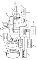
図1は、本発明の光学機器の第1の実施形態を説明するためのブロック図であり、リアフォーカスズームレンズ光学系を備えたデジタルスチルカメラやビデオカメラ等の撮像装置のズーム機構に本発明を適用した形態を示す。ここで、本実施形態のリアフォーカスズームレンズ光学系は、変倍レンズ(バリエータレンズ)と、変倍レンズより像面側に配置され変倍レンズの変倍動作(ズーム)に応じて変倍に伴う像面変動を補正(コンペンセータ作用)するように光軸方向に移動し、フォーカス調整のために光軸方向に移動するフォーカスレンズを有する構成とされ、たとえば物体側から、固定の正の第1レンズ群、変倍動作で移動する負の第2レンズ群、固定の正の第3レンズ群、コンペンセータ作用およびフォーカスのために移動する正の第4レンズ群で構成される4群リアフォーカスズームタイプの光学系が適用されている。なお、図1では、バリエータレンズ群14およびフォーカスレンズ群16を図示し、その他のレンズ群は図示を省略している。
(Embodiment 1)
FIG. 1 is a block diagram for explaining a first embodiment of an optical apparatus of the present invention. The present invention is applied to a zoom mechanism of an imaging apparatus such as a digital still camera or a video camera equipped with a rear focus zoom lens optical system. The form which applied is shown. Here, the rear focus zoom lens optical system according to the present embodiment has a variable power lens (variator lens) and a variable power lens that is arranged on the image plane side of the variable power lens and performs variable power according to the variable power operation (zoom) of the variable power lens. It is configured to have a focus lens that moves in the optical axis direction so as to correct the accompanying image plane variation (compensator action) and moves in the optical axis direction for focus adjustment. For example, from the object side, a fixed positive first 4-group rear focus zoom type comprising a lens group, a negative second lens group that moves by zooming operation, a fixed positive third lens group, a positive fourth lens group that moves for compensator action and focus The optical system is applied. In FIG. 1, the
図1において、1は外部から手動操作される操作部材であるフォーカスリングであり、2はこのフォーカスリングがエンドレスで(回転規制なく)回転できることを示す矢印である。3は外周に距離表示が書かれた表示リングであり、この図では、フォーカスリング同様のリング形状で示したが、本実施例においては、リング状である必要はなく、円弧状のものでもあるいは平板の形態であっても構わないが、いずれにしても、距離表示が書かれているものである。5は、この距離表示の∞の先に設けられたAFポジション表示である。6は∞から至近までの適当な距離に対する表示であり、ここでは、ワイド端の最至近撮影距離がレンズ直前の例えば2cmであれば、2cmもしくは0.02mの表示まで、この表示リング状に示されている。7は、フォーカスリングの回転状態を検出するパルスエンコーダーであり、フォトインタラプターと、フォトインタラプターの投受光素子あいだで、リングを回転に同期して遮蔽と透過をくりかえすように設けられた「くし歯」によるものや、ギア列を介して回転出力型のパルスエンコーダーを用いる手段などが考えられる。パルスエンコーダーとしては、上述の光学式のものや、MRセンサーホールセンサーなどの磁気式のものなどが考えられる。8はオートフォーカス(AF)とマニュアルフォーカス(MF)の切り替えスイッチで、スライドスイッチリーフスイッチなどで構成されるとともに、不図示の外部操作部により、撮影者により、AFとMFの選択を可能としている。9は表示リングの絶対位置エンコーダーで、表示リングがどの距離を表示しているか、あるいは、表示リングがAFポジションにあるかを検出する。10は表示リング駆動源である。表示リング駆動源にはDCモーターやリニアモーター、ステップモーター、などの周知のアクチュエーターが用いられるが、ここで、ステップモーターを用いた場合、前述の表示リング絶対位置エンコーダー9としては、ステップモーターへの駆動入力パルス数を、起算位置から連続的にカウントする方法を用いても良い。その場合の起算位置出しは、ここでは示していないフォトインタラプターを用いたり、所定時間所定パルスを同一方向に与えることで、表示リングを回転可能な端位置に突き当てることによっても構わない。
In FIG. 1, reference numeral 1 denotes a focus ring that is an operation member that is manually operated from the outside, and
表示リングには回転端を有しても有さなくても構わないが、本発明を実施するに当たっては、フォーカスリング1は操作者によりさわることが可能で、もちろん回転操作するものである一方、表示リング部は、操作者によって触れることは不可能となっている。 The display ring may or may not have a rotation end. However, in carrying out the present invention, the focus ring 1 can be touched by an operator and, of course, is rotated. The display ring part cannot be touched by the operator.
11は、CPUであり、12はCPU11内に設けられた、被写体距離に応じて、その被写体距離にピントが合った状態でズーム動作を行うための、フォーカスレンズとバリエーターレンズの位置関係を示すデータであるところの軌跡メモリである。通常は、数個の被写体距離に対する上記関連データが記憶されており、これらのデータから、任意の距離の被写体に対してもピントがずれることなくズーミングできる。
13はズーム駆動源で、変倍のためのバリエーターレンズ群を不図示の機構を介して、高精度に光軸を保持しながら、光軸方向に駆動する。14はこれにより駆動されるバリエーターレンズである(ここでは凸レンズとして示したが、凹レンズが用いられる場合もある)。15はズームエンコーダーであり、バリエーター位置を検出する。これは焦点距離を検出しているのと等価である。なお、前述した表示リングと同様に、ズーム駆動源としてステップモーターを用いる場合には、同様にフォトインタラプターなどで決まる起算位置から、ステップモーターへの入力パルス数を連続してカウントすることにより、ズームエンコーダー15の機能とすることもできる。
A
16はフォーカスレンズ群であり(ここでは凸レンズとして示したが、凹レンズが用いられる場合もある)、リアフォーカスレンズであるので、フォーカス機能だけではなく、ズーム中に同一距離のピントを維持するために、コンペンセータとしての機能も有しているから、ズーム動作時には、前述の軌跡メモリに基づく所定の関連を守るべく、バリエータレンズの動作に連動して最適に光軸方向に駆動される。あるいは、被写体距離が変化したときには、新たな被写体距離において正しいピントを得るために駆動される。
17はイメージセンサーである、CCDやC-MOSセンサー、等を示している。18は前述したとおり、フォーカスレンズ16を光軸方向に動かすための駆動源であり、19はフォーカスレンズの光軸方向の絶対位置を検出するためのフォーカスレンズ位置検出エンコーダーである。なお、前述したとおり、フォーカスレンズ駆動源にステップモーターを用いる場合には、起算位置からステップモーターへ入力した駆動パルスを連続的にカウントすることにより、フォーカス位置検出エンコーダー19の機能を果たすことが可能となる。
20は、操作者がズーム動作を行うためのテレワイドスイッチであり、図のようなシーソータイプのスイッチで、その押し込み量によってズーム速度の設定が可変となるなどの機能が知られている。
4は距離表示を確定するための指標であり、21は、指標の示す表示リング上の数値を読み取るための、アクリルなどの透明材料で出来た窓となっている。 4 is an index for determining the distance display, and 21 is a window made of a transparent material such as acrylic for reading the numerical value on the display ring indicated by the index.
以下上記のブロック構成よりなる本発明第一の実施例の動作を解説する。
ここでは
(1)AF動作時
(2)マニュアルフォーカスで、フォーカスリングを所定の速度v以下で回転動作させた場合
(3)マニュアルフォーカスで、フォーカスリングを所定の速度v以上で回転動作させた場合
(4)マニュアルフォーカスでピントの合っている被写体距離が、全焦点距離で撮影可能な最至近距離よりも近接側にあり、その状態からその距離でのピント合わせが不可能な焦点距離へズームした場合
の四つの動作状況について説明する。
The operation of the first embodiment of the present invention having the above block configuration will be described below.
here
(1) During AF operation
(2) When the focus ring is rotated at a predetermined speed v or less with manual focus
(3) When the focus ring is rotated at the specified speed v or higher with manual focus
(4) The subject distance in focus with manual focus is closer to the closest distance that can be taken at all focal lengths, and zooming from that state to a focal length where focusing at that distance is impossible The four operating situations will be described.
(1)AF動作時
操作者により、AF/MF切換えSW(スイッチ)がAF側にあると、このスイッチの状態がCPU11に取り込まれる。CPU11はそれを受けて表示リング駆動源10を駆動し、表示指標4が表示リング上のAF表示5を指し示すような位置まで、表示リングを駆動するものである。この際、正しく指標がAF表示を指し示していることは、表示リング絶対位置エンコーダーの出力をもって確認される。そのためには、CPU11に表示リング絶対位置エンコーダーと表示との位置関係があらかじめ記憶されているものである。AF/MF切換えSWがAFにある場合は、フォーカスリング1を操作してもこれは受け付けられない。
(1) During AF operation When the AF / MF switching SW (switch) is on the AF side by the operator, the state of this switch is captured by the
(2)マニュアルフォーカスで、フォーカスリングを所定の速度v以下で回転動作させた場合
AF/MF切換えSW(スイッチ)がMF側にあるときで、フォーカスリング1を回転させると、微小角度変位検出パルスエンコーダーによって、その回転方向と回転速度が検知され、CPU11に伝達される。このさい、表示リングの駆動可能な最速の回転角速度をv(°/sec)とする。このvは、機器の使用される様々な環境条件や姿勢差を含めて、駆動できる速度である。表示リング駆動源10にステップモーターを用いる場合には、上記の環境条件や姿勢条件を含めて脱調しない最高速度により表示リングの駆動可能最高速度v(°/sec)が定められる。
(2) When the focus ring is rotated at a predetermined speed v or less with manual focus
When the focus ring 1 is rotated when the AF / MF switching SW (switch) is on the MF side, the rotation direction and rotation speed are detected by the minute angular displacement detection pulse encoder and transmitted to the
表示リングがv(°/sec)で駆動したときに指標により指示される被写体距離に、フォーカスレンズ群16は、フォーカスレンズ駆動源によって駆動されることで、ピントが合うように追従する。一般的には、焦点距離が最も長焦点側(望遠端側)にあるときに、被写体距離変化に対して焦点を合わせなおすためのフォーカスレンズの移動量が大きくなる。もし、上記のごとく、表示リングの最高速度v(°/sec)を決めたとしても、その速度で表示が変化した刻々の新たな被写体距離に焦点が合うフォーカスレンズ位置へ、フォーカスレンズ16を動かす速度がフォーカスレンズ駆動源18に出せないのだとすると、この場合にはvとしては、フォーカスレンズ駆動源が、一般的は望遠端において駆動可能な最高速度からその速度を表示リングの回転速度に置き換えて、決まるものである。
The
撮影者により、このv以下の速度でフォーカスリング1が駆動されると、上記のようにvを定めているので、フォーカスリング1と表示リング3は、同じ回転角速度で移動するので、二つのリングは、あたかも一体であるかのように違和感なく動く。一例として、最短焦点距離状態で、表示リングが∞を示した状態から、0.02m(仮にこの距離を最至近距離とする)までのあいだを移動するのに、表示リング駆動源にステップモーターを用いたとして、これに1000パルスの入力パルスを必要としたと仮定し、ここでは簡単のために、表示リング駆動源10のステップモーターが入力パルス1パルスで駆動する回転角度と、微小角変位検出パルスエンコーダーの出力が1パルス変化するのに要する回転角度が同じであると仮定すると、微小角変位検出パルスエンコーダーが1パルス変化するたびに、表示リング駆動源を1パルス所定の方向に動かすとともに、それによって検出された表示リング絶対位置エンコーダーが示す被写体距離に、その焦点距離でピントが合うフォーカスレンズ16の位置を求め、その位置にフォーカスレンズ16が来るように、フォーカスレンズ駆動源を駆動する。このさい、フォーカスレンズが目標位置にあるかどうかはフォーカスレンズ位置検出エンコーダー19により検出される。また、焦点距離はズームエンコーダー15により、検出される。また、これらの操作の結果、表示および焦点の合っている被写体距離が∞となったあとも、操作者がフォーカスリング1を更に∞方向へ回したり、逆に表示及び焦点の合っている被写体距離がその焦点距離においてピント合わせた可能な最至近距離を示しかつその距離にピントが合っているにもかかわらず更に至近方向へフォーカスリング1を回した場合には、この動作があっても、ズーム駆動源、表示リング駆動源は、なんら動作させない。このようなご操作は、表示リングがフォーカスリングと一体で追従せずに、フォーカスリングを駆動しても表示リングが駆動しないことから視認することが可能である。また、表示リング同様の表示を、電子ビューファインダーに表示するとか、すでに∞または至近端にあることを知らせる表示、ブザー音、などを設けてもよい。前述の通り、ビデオやデジタルカメラで用いられるリアフォーカスレンズでは、焦点距離によって撮影可能な最至近距離が異なってくるので、表示リングの可動する至近距離側の可動範囲は焦点距離によって変化する。例えば焦点距離が最短焦点距離にあるときには0.02m表示まで表示リングは可動となり、実際にもその距離にピントを合わせることが可能となる。例えば焦点距離が最長焦点距離にあるときには0.8m表示まで表示リングは可動となり、実際にもその距離までしかピントを合わせることができない。
When the focus ring 1 is driven by the photographer at a speed equal to or less than v, since the value v is determined as described above, the focus ring 1 and the
(3)マニュアルフォーカスで、フォーカスリングを所定の速度v以上で回転動作させた場合。この場合には、上述(2)の説明で記したとおり、フォーカスリングと表示リングの回転角速度を同じに追従させることが出来ない。よって、フォーカスリングがv以上で操作されても、CPU11としては、フォーカスリングがvの速度で操作されたと同一と置き換えて、表示リングとフォーカスレンズ駆動源を動作させるものである。このように構成することにより、フォーカスリングと表示リングの一体的な回転動作はくずれるものの、上述の文献1などでは考慮されていなかった、操作リングを高速で操作した場合の表示と実際の焦点が合う距離にずれが生じたり、追従遅れが生じるといった問題点が解決される。
(3) When the focus ring is rotated at a predetermined speed v or higher with manual focus. In this case, as described in the description of (2) above, the rotational angular velocities of the focus ring and the display ring cannot follow the same. Therefore, even if the focus ring is operated at v or higher, the
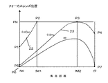
(4)マニュアルフォーカスでピントの合っている被写体距離が、全焦点距離で撮影可能な最至近距離よりも近接側にあり、その状態からその距離でのピント合わせが不可能な焦点距離へズームした場合。図2は、文献2などにも開示されているリアフォーカスレンズのバリエータレンズ群とフォーカスレンズ群の被写体距離に応じた位置関係を示す図である。図1の本発明において、AF/MF切換えSWがMF側にあり、その焦点距離で撮影可能な最至近撮影距離に焦点が合っているような状態から、ズーム操作を行った場合、その距離に焦点を合わせ続けることが出来なくなる。このような場合として、例えばワイド端で0.02cmの距離を最至近撮影距離として、この距離に焦点が合っているとすると、図2のP1という点に、バリエーターレンズ群とフォーカスレンズ群が位置していることとなる。ここから焦点距離が長くなる方向へズームを行うと、焦点距離fWからfM1までは0.02mに焦点が合った状態を維持できる0.02m軌跡(図2の22)の上に乗って、両レンズ群の位置関係が維持されたまま駆動されるので、焦点距離が変化しても焦点の合う被写体距離は変化せず、よって、図1のズームスイッチ20が操作されても、CPUはズーム駆動源とフォーカスレンズ駆動源を最適に駆動制御しながら、図2の22の関係を維持すればよい。fM1からさらにズーム操作が継続するとfM2までのあいだに、焦点合わせが可能な最至近距離が0.02mから0.8m(80cm)まで徐々に変化してしまう。したがって図2ではP2点からP3点までのあいだは、フォーカスレンズ駆動源は停止し、ズームレンズ駆動源はバリエーターレンズを駆動して焦点距離をfM1からfM2まで変化させるとともに、CPUはより細かく、焦点距離情報をズームエンコーダー15より読み取りながら、それぞれの焦点距離で設定されている撮影可能な最至近距離が表示されるように、表示リング駆動リングを駆動する。この結果P3において、焦点の合う距離は80cmとなる。ここから更に長焦点側にズーム操作が行われると、P3からP4までは図2の80cm軌跡23の関係を維持して、フォーカスレンズとバリエーターレンズが駆動される。表示は80cmのままであるので、表示リングは駆動しない。同様に他の被写体距離であっても、短焦点距離側から長焦点距離側へとズームする際に、この例では80cmであるところの全焦点距離で焦点をあわせることが可能な最至近距離よりも、より至近距離に焦点が合った状態からのズームが行われると、その距離の軌跡がP2またはP3点と同じフォーカスレンズ位置FNに至った焦点距離からfM2までのあいだに、この例では80cmまで焦点の合う距離が移動するから、このあいだには表示リング駆動源により表示リングが駆動するものである。尚、長焦点距離から短焦点距離方向へのズーム動作では、焦点の合っていた被写体距離に焦点が合わせられなくなることが、ここで想定しているタイプのリアフォーカスズームレンズではないので、問題にはならない。例えばfTで80cmに焦点が合っていれば、P4からP3、P5というように、その距離に焦点が合い続ける関係を維持するようにCPUが駆動源を制御するものである。
(4) The subject distance in focus with manual focus is closer to the closest distance that can be taken at all focal lengths, and zooming from that state to a focal length where focusing at that distance is impossible If. FIG. 2 is a diagram illustrating a positional relationship according to the subject distance between the variator lens group of the rear focus lens and the focus lens group disclosed in
図3は、本発明第一実施例のフォーカスレンズ駆動と上記(4)の場合の表示リング駆動のフローチャートである。ステップ24でスタートする。ステップ25でAF/MF切換えスイッチの状態がAFにあるかMFにあるかを検出する。検出した結果、AF側にあるときにはステップ26に至る。ステップ26では表示リングがAFを示しているかどうかが検出される。AFポジションを指してなければ、ステップ28にて表示リング駆動源を動かすことで、表示がAFになるようにする。表示がAFを示すと、ステップ27で表示リング駆動源を停止する。ステップ25にてMFが選択されていることを検出した場合、ステップ29にて現状の焦点距離を読み取る。次いでステップ30にて表示リング絶対位置エンコーダーの出力から、現在の表示リング指示距離を読み取る。ステップ31で、表示リングの指示距離が、その焦点距離で焦点合わせ可能な距離範囲内にあるかどうかが判定される。範囲外の場合には(すなわちその焦点距離での最至近距離よりさらに近い距離を指示していた場合)、ステップ32に至り、表示リングをその焦点距離での範囲内となる方向に駆動する。ステップ33でその焦点距離での撮影可能最至近距離(MOD)に指示が達したかどうかを判別する。達していた場合には、ステップ34で表示リング駆動源を停止する。
FIG. 3 is a flowchart of the focus lens drive and the display ring drive in the case (4) of the first embodiment of the present invention. Start at
ステップ31で表示リングの指示する被写体距離が、その焦点距離で焦点合わせが可能な距離範囲内であると判断されると、ステップ35に至る。ステップ35で、その焦点距離で表示リングが指示した被写体距離に焦点が合うフォーカスレンズ位置が「目標フォーカスレンズ位置」として算出決定される。ステップ36で、ステップ35で決まった目標位置と実際のフォーカスレンズ位置があっているかどうかを判別し、ずれがある場合、そのずれをゼロとする方向にステップ38でフォーカスレンズ駆動源を駆動する。ずれがなくなれば、ステップ37でフォーカスレンズ駆動源を停止する。
If it is determined in
図4は上記(4)の場合を除く、表示駆動源の駆動のためのフローチャートである。ステップ39よりスタートする。ステップ40にて、フォーカスリングの操作されている速度及び方向が検出される。ステップ41にて、ステップ40の検出の結果、フォーカスリングに操作が行われていたかどうかが判断される。もし何ら操作が検出されなければ、ステップ40に戻る。ステップ40の検出の結果、ステップ41でフォーカスリングに操作(変化)があったと判断された場合は、ステップ42にいたる。ステップ42で表示リングの位置を表示絶対位置エンコーダーの出力から読み取る。ついで、焦点距離を読み取る。これは、ズームエンコーダーにより検出されるものである。
FIG. 4 is a flowchart for driving the display drive source except for the case (4). Start from
ステップ44ではステップ43で検出した焦点距離における撮影可能最至近距離、すなわち至近端に表示リングが位置しているか、もしくは全焦点距離で共通の無限端に表示リングが位置しているかどうかが判断される。もし、至近端もしくは無限端状態になく、すなわち両端のあいだに表示リングが位置されている場合はステップ44の判定はNとなり、ステップ47に至る。一方その焦点距離での至近端(例えば焦点距離が図2のfWにあるときには0.02m、fM2にあるときは0.8mを表示しているようなとき)にあるか、無限端(∞表示のとき)のときにはステップ44の判断はYとなり、ステップ45に至る。ステップ45では、ステップ40で検出されたフォーカスリングの操作の方向が、表示がすでに至近端にあるのに至近方向であるか、もしくは表示がすでに無限端にあるのに無限方向であるか、が検出される。そのようにすでに表示が端にあるのにさらにその方向へのリング操作があってもそれは受け付けられない。よって、ステップ45の判定はYとなり、ステップ46にて、表示リング駆動源は停止となる。すなわち、端にあるのに端方向への駆動操作が操作リングにて行われても、この操作は受け付けられないので表示リングは駆動されないものである。
In
ステップ45の判定がNであれば、ステップ47に至る。表示リングが駆動可能な最高速度をV(°/sec)とし、ステップ40で検出されたフォーカスリングの回転速度をv(°/sec)とする。v<Vであれば、ステップ48にいたり、表示リングはvで駆動する。すなわち、表示リングと操作リングはともにvの速度で動くので、操作リングと表示リングはあたかも一体部品のように動作する。一方、ステップ47の判定がNであれば、vの速度で表示リングを駆動してもその速度でリングを動かせないので、動かせる最高速度であるVで表示リングを駆動するものである。
If the determination in
以上、図1〜図4を用いて、本発明実施例の構成、フローチャートについて説明した。図1のCPUは、図3、図4で説明したフローチャートによって駆動制御された表示リングの絶対位置を絶対位置エンコーダー9にて検出し、この検出結果と、焦点が合っている被写体距離のあいだでずれが生じないように、フォーカスレンズの位置を駆動制御するものである。 The configuration and flowchart of the embodiment of the present invention have been described above with reference to FIGS. The CPU in FIG. 1 detects the absolute position of the display ring that is driven and controlled according to the flowcharts described with reference to FIGS. 3 and 4 by the absolute position encoder 9, and between this detection result and the subject distance in focus. The position of the focus lens is driven and controlled so that no deviation occurs.
(第二実施例)
上述第一実施例においては、vとVの回転角速度の大小比較を行い、表示リングが追従不可能な速度で操作リングが操作された場合には、表示リングは駆動可能最高速度にて駆動されることで、表示リングと操作リングの駆動速度にはずれが生じてしまうものの、表示リング駆動源が誤動作を起こすことはなく構成している。これは例えば表示リング駆動源にステップモーターを用いた場合、ステップモーターの入力パルス数の起算位置からの連続したカウントにより表示絶対位置エンコーダーを構成できるわけであるが、このさい、V以上の駆動命令でステップモーターを駆動した結果として脱調(入力ステップに正しくステップモーターが応答しないような状況)が起きると、エンコーダーの検出にもずれが生じてしまうことが発生し、しいては表示と実際のピントの合っている被写体距離が合致しないといった問題が発生してしまう。
(Second embodiment)
In the first embodiment described above, the rotational angular velocities of v and V are compared, and when the operation ring is operated at a speed that the display ring cannot follow, the display ring is driven at the maximum drivable speed. As a result, the display ring and the operating ring are configured so that the display ring driving source does not malfunction, although the display ring and the operating ring are driven at different speeds. For example, when a step motor is used as the display ring drive source, a display absolute position encoder can be configured by continuously counting the number of input pulses of the step motor from the starting position. If a step-out occurs as a result of driving the step motor in (a situation where the step motor does not respond correctly to the input step), the encoder detection may also shift, and the display and actual There arises a problem that the subject distance in focus does not match.
しかし第一実施例では、表示リングと操作リングの回転角速度の関係については上述のごとく考慮しているが、表示リングの指示に基づいて位置を変えるフォーカスレンズの駆動を行っているフォーカスレンズ駆動源の仕様については言及していない。フォーカスレンズ駆動源として比較的高速の駆動ができるリニアアクチュエーターなどを用いる場合は、表示リングの位置に追従駆動することは容易な場合もあるが、フォーカスレンズ駆動源に前述の例と同様にステップモーターを用いる場合には、あまり高速の駆動命令を与えても脱調を起こす可能性がある。図2から明確なように、無限距離から例えば0.8mまでピントの合う距離を変更する場合、ワイド端ではP6からP5までフォーカスレンズを移動すればよいのに対し、テレ端ではP7からP4までと、ワイド端に比べて多くの量、フォーカスレンズの位置を移動しなければならない。例えばこの場合(無限から0.8m)でいえば、ワイド側よりテレ側の方が、同じ操作リング(もしくは表示リング)の駆動速度でピントの合う距離の変更命令が行われたとしても、実際のフォーカスレンズ駆動源が、その変更に追従するために用いる速度はテレ側になるほど高速が求められる。よって、想定した表示リングの使用可能最高速度で表示が変化した場合に、テレ端(もしくはこの例ではワイド端での0.8mから0.02mといったマクロ領域での使用)でのフォーカスレンズ駆動源の使用最高速度をもっていすれば追従可能であれば問題ないが、追従が難しい場合、表示リングの動きにフォーカスリングの動きが追従できない場合もある。よって本発明第二実施例ではフォーカスレンズ駆動源の使用最高速度VFも考慮し、表示と実際の焦点の合う距離にずれがないようにするものである。 However, in the first embodiment, the relationship between the rotational angular velocities of the display ring and the operation ring is considered as described above, but the focus lens driving source that drives the focus lens whose position is changed based on the instruction of the display ring. The specification of is not mentioned. When a linear actuator that can be driven at a relatively high speed is used as the focus lens drive source, it may be easy to drive following the position of the display ring. However, a step motor is used as the focus lens drive source as in the previous example. In the case of using, there is a possibility of causing a step-out even if a drive command of too high speed is given. As is clear from FIG. 2, when changing the in-focus distance from an infinite distance to 0.8 m, for example, the focus lens may be moved from P6 to P5 at the wide end, while from P7 to P4 at the tele end. Therefore, the position of the focus lens must be moved by a large amount compared to the wide end. For example, in this case (from infinite to 0.8 m), even if the tele side is instructed to change the in-focus distance at the same operating ring (or display ring) drive speed than the wide side, The speed used by the focus lens drive source to follow the change is required to be higher as the telephoto side becomes closer. Therefore, when the display changes at the maximum usable speed of the assumed display ring, the focus lens drive source is used at the tele end (or in this example, the macro range from 0.8 m to 0.02 m at the wide end). If it is possible to follow the maximum speed, there is no problem as long as it is possible to follow, but if it is difficult to follow, the movement of the focus ring may not follow the movement of the display ring. Therefore, in the second embodiment of the present invention, the maximum operating speed VF of the focus lens driving source is also taken into consideration so that there is no deviation in the distance between the display and the actual focus.
図5は図4に対して第二実施例のフローチャートである。第二実施例ではステップ50にてVを定めている。ここでVは上述のようにその焦点距離におけるフォーカスレンズ駆動源の使用可能最高速度から定まる、対応可能な焦点表示リングの追従可能最高速度を定めるものであり、焦点距離がワイド側では表示リング駆動源の能力により、テレ側では(場合によっては)フォーカスレンズ駆動源の能力によって定まるものである。
FIG. 5 is a flowchart of the second embodiment with respect to FIG. In the second embodiment, V is determined at
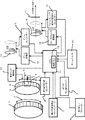
(第3実施例)表示リングでの距離表示は、電子ビューファインダーを覗いている場合などには撮影者がファインダーと同時に視認することが出来ない。したがって、そのような場合を考慮して、表示リング絶対位置エンコーダーの検出結果をもとに電子ビューファインダーに距離表示を行うことができる。図5は図1のブロック図に対してブロック51にて、電子ビューファインダー内への距離表示を可能としている。
(Third Embodiment) The distance display on the display ring cannot be viewed by the photographer at the same time as the viewfinder when looking into the electronic viewfinder. Therefore, considering such a case, distance display can be performed on the electronic viewfinder based on the detection result of the display ring absolute position encoder. FIG. 5 shows a distance display in the electronic viewfinder at
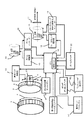
(第4実施例)AF/MF切り替えスイッチがAF側にある場合、AF動作が行われ、操作リングの操作は受け付けられず、表示はAFを示して固定される。この場合に、操作者の意図によりあるフォーカス状態を維持するためにAFを切りたいという場合への対応が第1〜第3実施例では不明確であった。図6のブロック図ではブロック52にワンショットAF操作キーを設けている。これはスライドスイッチもしくはプッシュスイッチなどで構成されAF動作状態からスライドスイッチを「フォーカス保持」側へ切り替えたりあるいはプッシュスイッチを押しつづける(もしくは一度押す)などの何らかの定められた動作をすることにより、AFポジションにありながらその操作が行われた状態にフォーカスレンズが固定されるものである。あるいはその状態からズームを行えばその距離にピントが合った状態が維持されてズームが行われるものである。このようにすることでオートフォーカスによって所望の被写体にピントを合わせたあとに、このキーの操作を行えば、不必要なピント移動(例えば被写体の前を何かが横切ったときにその横切ったものにピントが合うようにフォーカスレンズが動いてしまうとか、作画意図によってフォーカスエリアから所望被写体が外れた場合に、所望被写体へのピントがずれてしまうような動作)を避ける事ができる。
(Embodiment 4) When the AF / MF selector switch is on the AF side, AF operation is performed, operation of the operation ring is not accepted, and the display is fixed to indicate AF. In this case, it is unclear in the first to third embodiments how to turn off AF in order to maintain a certain focus state according to the operator's intention. In the block diagram of FIG. 6, a one-shot AF operation key is provided in the
尚、上述第1〜第4の実施例は撮影レンズが撮像装置本体に対して交換可能なレンズにおいても構成することができる。この場合電子マウントを介して、レンズ側に設けられたマイコンと撮像装置本体側に設けられたマイコンのあいだで通信が行われる。例えば前述第三実施例の場合、これらのマイコン間の通信により被写体距離情報がレンズから撮像装置本体に送られ、撮像装置側にある電子ビューファインダーに距離表示が行われる。 The first to fourth embodiments described above can also be configured in a lens in which the photographing lens can be exchanged with respect to the imaging apparatus main body. In this case, communication is performed between the microcomputer provided on the lens side and the microcomputer provided on the imaging apparatus main body side via the electronic mount. For example, in the case of the third embodiment described above, subject distance information is sent from the lens to the imaging apparatus body through communication between these microcomputers, and the distance is displayed on the electronic viewfinder on the imaging apparatus side.
1 操作リング
5 表示リング
14 バリエータレンズ群
16 フォーカスレンズ群
9 表示リング絶対位置エンコーダー
11 CPU
12 軌跡メモリ
13 ズーム駆動源
18 フォーカスレンズ駆動源
20 ズームキー
10 表示リング駆動源
1
12
Claims (1)
上記表示部材の可動範囲内の絶対位置を検出する表示部材位置検出手段と、
上記操作部材の操作に関する情報を検出するリング操作検出手段と、
前記表示部材を駆動する表示部材駆動源と、
焦点距離検出手段と、
制御手段と、を有し、
前記制御手段は焦点距離に応じて、前記表示部材の至近側の可動範囲端を、前記メカ的な規制範囲より内側で可変設定することを特徴とした光学機器の制御装置。 A first display member whose in-focus distance is displayed and whose movable range is mechanically restricted, and an operation member operable endlessly;
Display member position detecting means for detecting an absolute position within the movable range of the display member;
A ring operation detecting means for detecting information relating to the operation of the operation member;
A display member drive source for driving the display member;
A focal length detection means;
Control means, and
The control device for an optical apparatus, wherein the control means variably sets a movable range end on the near side of the display member inside the mechanical regulation range according to a focal length.
Priority Applications (1)
| Application Number | Priority Date | Filing Date | Title |
|---|---|---|---|
| JP2004237298A JP2006058367A (en) | 2004-08-17 | 2004-08-17 | Optical equipment |
Applications Claiming Priority (1)
| Application Number | Priority Date | Filing Date | Title |
|---|---|---|---|
| JP2004237298A JP2006058367A (en) | 2004-08-17 | 2004-08-17 | Optical equipment |
Publications (1)
| Publication Number | Publication Date |
|---|---|
| JP2006058367A true JP2006058367A (en) | 2006-03-02 |
Family
ID=36105902
Family Applications (1)
| Application Number | Title | Priority Date | Filing Date |
|---|---|---|---|
| JP2004237298A Withdrawn JP2006058367A (en) | 2004-08-17 | 2004-08-17 | Optical equipment |
Country Status (1)
| Country | Link |
|---|---|
| JP (1) | JP2006058367A (en) |
Cited By (4)
| Publication number | Priority date | Publication date | Assignee | Title |
|---|---|---|---|---|
| JP2011138018A (en) * | 2009-12-28 | 2011-07-14 | Canon Inc | Image pickup apparatus including focus operating apparatus and focus control method |
| JP2014206726A (en) * | 2013-03-21 | 2014-10-30 | パナソニック株式会社 | Lens barrel and imaging apparatus including the same |
| WO2015002062A1 (en) | 2013-07-02 | 2015-01-08 | オリンパス株式会社 | Control method for image pickup device and interchangeable lens |
| JP2015079106A (en) * | 2013-10-17 | 2015-04-23 | キヤノン株式会社 | Lens device and image capturing device |
-
2004
- 2004-08-17 JP JP2004237298A patent/JP2006058367A/en not_active Withdrawn
Cited By (5)
| Publication number | Priority date | Publication date | Assignee | Title |
|---|---|---|---|---|
| JP2011138018A (en) * | 2009-12-28 | 2011-07-14 | Canon Inc | Image pickup apparatus including focus operating apparatus and focus control method |
| JP2014206726A (en) * | 2013-03-21 | 2014-10-30 | パナソニック株式会社 | Lens barrel and imaging apparatus including the same |
| WO2015002062A1 (en) | 2013-07-02 | 2015-01-08 | オリンパス株式会社 | Control method for image pickup device and interchangeable lens |
| US9794470B2 (en) | 2013-07-02 | 2017-10-17 | Olympus Corporation | Photographing apparatus and interchangeable lens control method |
| JP2015079106A (en) * | 2013-10-17 | 2015-04-23 | キヤノン株式会社 | Lens device and image capturing device |
Similar Documents
| Publication | Publication Date | Title |
|---|---|---|
| US5973857A (en) | Photo-taking lens and optical apparatus | |
| US5060001A (en) | Optical apparatus | |
| US10139587B2 (en) | Lens barrel and optical apparatus | |
| JP5537539B2 (en) | Optical equipment | |
| JPH04254809A (en) | Lens position adjusting device | |
| US6670989B2 (en) | Optical system driving control device and camera using the same | |
| JP5590903B2 (en) | IMAGING LENS, IMAGING DEVICE, AND IMAGING DEVICE CONTROL METHOD | |
| EP1591819A1 (en) | Drive controller of a lens system | |
| JP2006078638A (en) | Optical equipment | |
| JP2006058367A (en) | Optical equipment | |
| JP4590153B2 (en) | Optical equipment | |
| JPH06100707B2 (en) | Magnification switching device | |
| JP2004233892A (en) | Optical equipment | |
| JP3244773B2 (en) | Optical equipment | |
| JP5159504B2 (en) | Optical equipment | |
| US5249010A (en) | Apparatus for controlling a zooming optical device | |
| JP3584088B2 (en) | Optical equipment | |
| JP2002189163A (en) | Optical device and photographing device | |
| JP2018194758A (en) | Optical instrument | |
| JP7175677B2 (en) | optical equipment | |
| JP7208181B2 (en) | Control device, lens device, imaging device, control method, and program | |
| JP3176082B2 (en) | Optical apparatus having lens position control device | |
| JP4628015B2 (en) | AF control device for zoom lens | |
| JP3210488B2 (en) | Lens position control device and optical equipment | |
| JP2001069793A (en) | Driving device with stepping motor and device with the driving device, light quantity adjusting device, and optical equipment |
Legal Events
| Date | Code | Title | Description |
|---|---|---|---|
| A300 | Application deemed to be withdrawn because no request for examination was validly filed |
Free format text: JAPANESE INTERMEDIATE CODE: A300 Effective date: 20071106 |