JP2006040468A - Optical disc apparatus and optical disc tilt control method - Google Patents
Optical disc apparatus and optical disc tilt control method Download PDFInfo
- Publication number
- JP2006040468A JP2006040468A JP2004221567A JP2004221567A JP2006040468A JP 2006040468 A JP2006040468 A JP 2006040468A JP 2004221567 A JP2004221567 A JP 2004221567A JP 2004221567 A JP2004221567 A JP 2004221567A JP 2006040468 A JP2006040468 A JP 2006040468A
- Authority
- JP
- Japan
- Prior art keywords
- tilt
- amount
- optical disc
- speed
- tilt amount
- Prior art date
- Legal status (The legal status is an assumption and is not a legal conclusion. Google has not performed a legal analysis and makes no representation as to the accuracy of the status listed.)
- Pending
Links
Images
Landscapes
- Optical Recording Or Reproduction (AREA)
Abstract
【課題】光ディスク装置における複数の速度に対するチルト量の測定時間を短縮すること。
【解決手段】装着された光ディスクをある1つの速度V1で回転させ、光ディスクからの反射光を光ピックアップにて検出し、ディスク面のチルト量θ1を測定する。測定したチルト量θ1を基に、他の速度V2におけるチルト量θ2を演算により求め、測定及び演算にて求めた各速度でのチルト量θに従い光ピックアップのチルトを制御する。演算式として、ディスク回転時に受ける遠心力によるディスク変形式を用いる。
【選択図】図1
An object of the present invention is to reduce a tilt amount measurement time for a plurality of speeds in an optical disc apparatus.
A is rotated at one speed V 1 in the mounted optical disc, and detecting the reflected light from the optical disk by the optical pickup to measure the amount of tilt theta 1 of the disk surface. Based on the measured tilt amount θ 1 , the tilt amount θ 2 at another speed V 2 is obtained by calculation, and the tilt of the optical pickup is controlled according to the tilt amount θ at each speed obtained by measurement and calculation. As a calculation formula, a disc deformation formula using a centrifugal force received when the disc rotates is used.
[Selection] Figure 1
Description
本発明は、光ディスクに信号を記録再生する際に、回転するディスクに発生するチルト量に対し最適に制御する光ディスク装置およびチルト制御方法に関する。 The present invention relates to an optical disc apparatus and a tilt control method for optimally controlling a tilt amount generated in a rotating disc when a signal is recorded on and reproduced from an optical disc.
光ディスク装置において、光ピックアップを光ディスクに対して垂直になるよう制御されている。装着されたディスクに垂直方向からの傾き、いわゆるチルトがあると、レーザ光のスポットが歪むために情報記録面の単位面積あたりの照射光量が減少し、記録不足状態になる。そこで、ディスク挿入時やライト直前にディスクのチルト量を測定し、ライト時はそのチルト量分だけレンズチルト制御機構により補正する。またはそのチルト量により減少する照射光量分だけパワーを上げて、記録不足を補っている。 In the optical disc apparatus, the optical pickup is controlled to be perpendicular to the optical disc. If the mounted disc has a tilt from the vertical direction, that is, a so-called tilt, the laser light spot is distorted, so that the amount of irradiation light per unit area of the information recording surface is reduced, resulting in an insufficient recording state. Therefore, the tilt amount of the disc is measured when the disc is inserted or just before writing, and the amount of tilt is corrected by the lens tilt control mechanism when writing. Alternatively, the recording power is compensated for by increasing the power by the amount of irradiation light that decreases with the tilt amount.
一方、ディスクのチルト量はディスクの回転速度により変化し、その変化量はディスクの種類に依存する。ディスクの面ぶれや偏心が大きい場合やレーザーパワーが足りない場合には、ライトスピード(=ディスクの回転速度)を下げて記録する。記録中にスピードを変更する場合は、予め、使用する各々のスピードでのディスクのチルトを測定する必要があった。 On the other hand, the tilt amount of the disk changes depending on the rotational speed of the disk, and the amount of change depends on the type of the disk. When the disc surface shake or eccentricity is large, or when the laser power is insufficient, recording is performed at a lower write speed (= rotation speed of the disc). When changing the speed during recording, it was necessary to measure the tilt of the disk at each speed used beforehand.
ディスクのチルトは回転速度により変化する。従来よりチルトを測定する方法はあるが、特許文献1のように回転速度を変化させて各速度毎にチルトを測定していた。
The tilt of the disc changes depending on the rotation speed. Conventionally, there is a method of measuring the tilt, but as in
ディスクのチルトは回転速度により変化する。従来のチルトを測定する方法では、特許文献1のように異なる回転速度毎にチルト量を測定していた。そのため測定の時間がかかり、光ディスクの高速記録を実現する上で妨げになっていた。
The tilt of the disc changes depending on the rotation speed. In the conventional method for measuring the tilt, the tilt amount is measured for each different rotational speed as in
本発明の目的は、複数の速度に対するチルト量の測定時間の短縮を図ることにある。 An object of the present invention is to shorten the measurement time of the tilt amount for a plurality of speeds.
本発明による光ディスク装置は、装着された光ディスクを複数の速度で回転可能な回転手段と、光ディスクを所定の速度V1で回転させ、光ディスクからの反射光を光ピックアップにて検出し、光ディスク面のチルト量θ1を測定するチルト測定手段と、測定したチルト量θ1を基に、他の速度V2におけるチルト量θ2を演算により求めるチルト演算手段と、チルト演算手段で使用する演算式を記憶する記憶手段と、チルト演算手段で求めた各速度でのチルト量θに従い、光ピックアップのチルト量を制御するチルト制御手段とを備える。 Optical disc apparatus according to the present invention, a rotatable rotation means mounted optical disk at a plurality of speeds, the optical disk is rotated at a predetermined speed V 1, to detect the reflected light from the optical disk by the optical pickup, the optical disc surface a tilt measuring means for measuring the amount of tilt theta 1, based on the amount of tilt theta 1 was measured, and the tilt calculation means for obtaining by calculation the amount of tilt theta 2 in the other velocity V 2, the arithmetic expression used in the tilt calculation means Storage means for storing, and tilt control means for controlling the tilt amount of the optical pickup according to the tilt amount θ at each speed obtained by the tilt calculating means.
ここにチルト測定手段は、光ディスク上の各半径位置においてチルト量θ1を測定し、チルト演算手段は、各半径位置において測定したチルト量θ1を基に、他の速度V2において各半径位置におけるチルト量θ2を演算により求めるものである。 Here, the tilt measuring means measures the tilt amount θ 1 at each radial position on the optical disc, and the tilt calculating means, based on the tilt amount θ 1 measured at each radial position, at each radial position at another velocity V 2 . those obtained by calculating the amount of tilt theta 2 in.
本発明による光ディスク装置のチルト制御方法は、装着された光ディスクを所定の速度V1で回転させ、光ディスクからの反射光を光ピックアップにて検出し、光ディスク面のチルト量θ1を測定し、測定したチルト量θ1を基に、他の速度V2におけるチルト量θ2を演算により求め、測定及び演算にて求めた各速度でのチルト量θに従い、光ピックアップのチルトを制御するものである。 In the tilt control method of the optical disc apparatus according to the present invention, the mounted optical disc is rotated at a predetermined speed V 1 , the reflected light from the optical disc is detected by an optical pickup, and the tilt amount θ 1 of the optical disc surface is measured and measured. Based on the obtained tilt amount θ 1 , the tilt amount θ 2 at another speed V 2 is obtained by calculation, and the tilt of the optical pickup is controlled according to the tilt amount θ at each speed obtained by measurement and calculation. .
本発明によれば、複数の速度に対するチルト量の測定時間を大幅に短縮することができ、光ディスク装置の記録再生の高速化に寄与する。 According to the present invention, it is possible to greatly reduce the time for measuring the tilt amount for a plurality of speeds, which contributes to an increase in the recording / reproducing speed of the optical disc apparatus.
以下、本発明による光ディスク装置および光ディスクのチルト制御方法の実施形態を図面を用いて説明する。 Embodiments of an optical disc apparatus and an optical disc tilt control method according to the present invention will be described below with reference to the drawings.
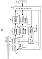
図1は、本発明による光ディスク装置の一実施例を示すブロック図である。この装置では、光ピックアップ3からレーザー光を光ディスク1に照射し、ディスクチルトの測定およびデータの記録・再生を行う。光ディスク1はスピンドルモータ2で所定の速度で回転させる。光ピックアップ3は、スレッド機構5により半径方向の所望位置に移動させる。
FIG. 1 is a block diagram showing an embodiment of an optical disc apparatus according to the present invention. In this apparatus, the
記録データは、記録信号形成回路6にて変調され、所定の記録パルス信号を形成する。レーザドライバ4は、記録パルス信号を基に、光ピックアップ3からレーザー光を光ディスクに照射させる。一方光ディスク1からの反射光は、光ピックアップ3の受光素子にて電気信号に変換する。このうちRF信号はRF信号増幅回路7にて増幅され、データ復調回路8にて再生データの復調が行われる。
The recording data is modulated by the recording
またフォーカス・トラッキングエラー信号検出回路9は、再生された信号からフォーカスエラー信号・トラッキングエラー信号を検出する。フォーカス・トラッキング・レンズチルト制御回路10は、トラッキングエラー信号のメインプシュプル信号(MPP)を測定し、MPP信号が最大になるようにレンズチルトを制御する。MPP信号が最大になるレンズチルト量を、当該ディスクのチルト量の測定値として、システムコントローラ11へ送る。システムコントローラ11は、測定されたチルト量を受け取り、これを基に演算により異なる速度におけるチルト量を求める。メモリ12には、チルト量演算式、および測定したチルト量などを格納する。
The focus / tracking error
データ記録・再生時は、システムコントローラ11は、記録・再生しようとするトラックの半径位置毎に、かつ速度毎にメモリ12に格納された演算式によりチルト量を演算する。演算したチルト量に基づいて、フォーカス・トラッキング・レンズチルト制御回路10は光ピックアップ3のレンズチルト機構を最適角度状態に制御する。この状態でデータの記録・再生を実行する。
At the time of data recording / reproduction, the
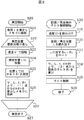
図2は、図1の光ディスク装置における光ディスクのチルト制御方法の一例を示すフローチャートである。 FIG. 2 is a flowchart showing an example of an optical disc tilt control method in the optical disc apparatus of FIG.
はじめに、チルト量の測定(S20)について述べる。チルトの測定は、ディスク装着時、セットアップ時または記録/再生開始直前に行う。ステップ21にて、ディスク板厚tを測定しメモリ12に格納する。ここに板厚tは、より正確には、フォーカスエラー信号へのオフセット印加量を可変したときのMPP信号を測定し、MPP信号が最大になるときのオフセット印加量から求めることができる。
First, the tilt amount measurement (S20) will be described. Tilt is measured when the disc is loaded, at the time of setup, or immediately before recording / playback. At
以下、ステップ22からステップ22’までの区間を、測定位置個数分だけ繰り返す。
Thereafter, the section from
ステップ23では、ディスクを予め定めた速度V1にて回転させ(例えば低速の8倍速とする)、ステップ24では、半径方向Lの位置にピックアップを移動させる。ステップ25では、位置Lにおけるディスクチルト量θ1を測定する。チルト量の測定は、MPP信号が最大になるレンズチルト量を、その位置Lにおけるディスクのチルト量とする。
In
ステップ26では、上記V1,L,t,θ1の値より、静止状態(V=0)を仮定した場合の静止チルト量θ0に対するsinθ0の値(1)式により計算し、メモリに格納する。(1)式の導出については後述する。
sinθ0=sinθ1{1+(n/t3)・(V1/L)2} (n:固定値) (1)
ステップ23から26までの工程を、半径方向の測定位置個数分だけ繰り返し、各L位置におけるsinθ0を求める。
In step 26, the V 1, L, t, theta than one value, calculated by the value (1) of the sin [theta 0 with respect to the stationary tilt amount theta 0 assuming a static state (V = 0), the memory Store. Derivation of the equation (1) will be described later.
sinθ 0 = sinθ 1 {1+ (n / t 3 ) · (V 1 / L) 2 } (n: fixed value) (1)
次にデータの記録/再生時のチルト制御(S30)について述べる。ステップ31にて、記録/再生実行時の現在の速度V2を読み出し、またステップ32にて、現在の記録/再生位置Lを読み出す。ステップ33にて、位置Lに対するsinθ0の値をメモリからロードする。ステップ34にて、上記V2,L,tにおけるチルト量θ2を(2)式により演算する。(2)式の導出については後述する。
θ2=sin−1[sinθ0/{1+(n/t3)・(V2/L)2}] (n:固定値) (2)
ステップ35では、フォーカス・トラッキング・レンズチルト制御回路10は、演算したチルト量θ2に従い、光ピックアップ3のレンズチルトを最適角度方向に制御する。
Next, tilt control (S30) during data recording / reproduction will be described. In
θ 2 = sin −1 [sin θ 0 / {1+ (n / t 3 ) · (V 2 / L) 2 }] (n: fixed value) (2)
In
メモリ12には上記演算式(またはその係数)だけでなく、チルト量θ2の演算結果を格納しておけば、再度、同速度同位置で制御する際には、その結果を読み出すだけで演算する必要がなくなる。また、演算は他の装置で行い、メモリ12にはチルト量θ2の演算結果のみをテーブル形式で格納しておき、速度と半径方向位置に対応するチルト量を読み出す方式でも良い。
If not only the above equation (or its coefficient) but also the calculation result of the tilt amount θ 2 is stored in the
本実施例では、ディスクのチルト量は1回測定するだけであり、ディスクのチルト量の速度による変化量は、速度及びディスクの板厚から演算することにより求めることができる。各々の速度でのディスクのチルトを測定を行う必要がなく、ディスク挿入時のセットアップ時間または記録/再生時間を短縮することができる。 In this embodiment, the amount of tilt of the disk is measured only once, and the amount of change in the amount of tilt of the disk depending on the speed can be obtained by calculating from the speed and the thickness of the disk. It is not necessary to measure the tilt of the disc at each speed, and the setup time or recording / playback time when inserting the disc can be shortened.
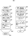
図3は、図1の光ディスク装置における光ディスクのチルト制御方法の他の例を示すフローチャートである。 FIG. 3 is a flowchart showing another example of the optical disc tilt control method in the optical disc apparatus of FIG.
はじめに、チルト量の測定(S40)について述べる。ステップ41にて、ディスク板厚tを測定しメモリ12に格納する。
First, the tilt amount measurement (S40) will be described. In step 41, the disk thickness t is measured and stored in the
以下、ステップ42からステップ42’までの区間を、測定位置個数分だけ繰り返す。
Thereafter, the section from
ステップ43では、ディスクを予め定めた速度V1にて回転させ、ステップ44では、半径方向Lの位置にピックアップを移動させる。ステップ45では、位置Lにおけるディスクチルト量θ1を測定し、V1,θ1の値をメモリに格納する。ステップ43から46までの工程は、半径方向の測定位置個数分だけ繰り返し、各L位置におけるチルト量θ1を求める。
In
次にデータの記録/再生時のチルト制御(S50)について述べる。ステップ51にて、記録/再生実行時の現在の速度V2を読み出し、またステップ52にて、記録/再生位置Lを読み出す。ステップ53にて、位置Lに対するθ1の値をメモリからロードする。ステップ54にて、上記V2,L,tにおけるチルト量θ2を(3)の近似式により算出する。この式は、チルト量θ2が速度に対してほぼ反比例するとしたものである。
θ2≒θ1・(a/t3)・(V1/V2) (a:固定値) (3)
ステップ55では、フォーカス・トラッキング・レンズチルト制御回路10は、算出したチルト量θ2に従い、光ピックアップ3のレンズチルトを制御する。
Next, tilt control (S50) during data recording / reproduction will be described. In step 51, it reads the recording / current speed V 2 during regeneration execution, also in step 52, reads the recording / reproducing position L. In
θ 2 ≈ θ 1 · (a / t 3 ) · (V 1 / V 2 ) (a: fixed value) (3)
In
本実施例では、チルト量が小さい領域で有効な近似式を用いることで、演算がより容易になる。 In the present embodiment, the calculation becomes easier by using an approximate expression that is effective in a region where the tilt amount is small.
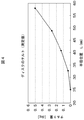
次に、上記実施例1、2において測定したチルト量、および演算にて求めたチルト量の一例を示す。 Next, an example of the tilt amount measured in the first and second embodiments and the tilt amount obtained by calculation will be shown.
図4は、測定したディスクチルト量の一例を示す図である。速度は低速の8倍速とし、各半径位置Lにおけるチルト量をプロットしている。ディスクの反り変形のため、外周位置ほどチルト量が増大することを示している。ディスクの内周から外周までの数個所にてディスクのチルト量を測定し、線形補間により半径位置対ディスクチルト量の関係式を求めれば、任意の半径位置におけるチルト量を求めることができる。 FIG. 4 is a diagram showing an example of the measured disc tilt amount. The speed is set to 8 times lower speed, and the tilt amount at each radial position L is plotted. It shows that the tilt amount increases toward the outer peripheral position due to the warp deformation of the disk. The tilt amount at an arbitrary radial position can be obtained by measuring the tilt amount of the disk at several locations from the inner periphery to the outer periphery of the disc and obtaining the relational expression of the radial position versus the disc tilt amount by linear interpolation.
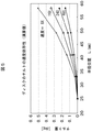
図5は、図4の測定結果を基に、異なる速度におけるチルト量を演算にて求めた結果の一例を示す図である。速度として、16倍速、24倍速、48倍速の場合の各半径位置におけるチルト量をプロットしている。高速になるほどチルト量は減少することを示している。 FIG. 5 is a diagram illustrating an example of a result obtained by calculating a tilt amount at different speeds based on the measurement result of FIG. As the speed, the tilt amount at each radial position in the case of 16 times speed, 24 times speed and 48 times speed is plotted. It shows that the tilt amount decreases as the speed increases.
以下、本実施例で採用するチルト量演算方法について説明する。 Hereinafter, a tilt amount calculation method employed in this embodiment will be described.
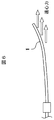
図6は、回転中の光ディスク1の変形を模式的に示す図である。ディスクチルトは、ディスク表面の反りやセッティング不良に伴い発生する。ディスクを回転させると、ディスクの各部に遠心力が働き、この遠心力によりディスクのチルト量は減少する。遠心力は速度に依存する。また遠心力によるディスクのチルト量への影響は、ディスク板厚に依存する。
FIG. 6 is a diagram schematically showing the deformation of the rotating
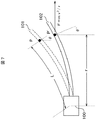
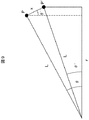
図7〜図9は、光ディスクに働く遠心力により光ディスクの変形量を解析する図である。 7 to 9 are diagrams for analyzing the deformation amount of the optical disk by the centrifugal force acting on the optical disk.
図7において、破線101は静止状態のディスク形状、実線102は回転状態のディスク形状を示す。パラメータLはディスク中心100から注目するディスク上の点Pまでの距離(ディスク面に沿って測った半径)、mは点Pの質量(質点)、θはチルト量、vは線速度である。遠心力によって点PはP’に移動し、チルト量がθ’に変化したとき、遠心力はF=mv2/rとなる。rはP’をチルト量0の面に投影した点から中心100までの距離とする。
In FIG. 7, a
図8は、この時の力の釣り合い状態を示す。xをPとP’間の距離、kをPでのばね係数とすると、kx=(mv2/r)・sinθ’が近似的に成り立つ。したがって、
x=[{m/(k・r)}・v2]・sinθ’ (4)
また図7を図9のように簡略すると、
r=Lcosθ’ (5)
Lsinθ−xcosθ”=Lsinθ’ (6)
と表すことができる。
cosθ’≒1、cosθ”≒1であるので、(4)(5)(6)より、
sinθ’=sinθ/{1+(m/k)・(v/L)2} (7)
と表せる。
FIG. 8 shows the force balance state at this time. When x is a distance between P and P ′ and k is a spring coefficient at P, kx = (mv 2 / r) · sin θ ′ is approximately established. Therefore,
x = [{m / (k · r)} · v 2 ] · sin θ ′ (4)
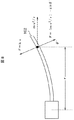
7 is simplified as shown in FIG.
r = Lcosθ ′ (5)
Lsinθ−xcosθ ″ = Lsinθ ′ (6)
It can be expressed as.
Since cos θ′≈1 and cos θ ″ ≈1, from (4) (5) (6)
sinθ ′ = sinθ / {1+ (m / k) · (v / L) 2 } (7)
It can be expressed.
ここにkは板厚tの3乗に比例し、またmはディスク間で差がないと仮定すると、
sinθ’=sinθ/{1+(n/t3)・(v/L)2} (n:固定値) (8)
θ’=sin−1〔sinθ/{1+(n/t3)・(v/L)2}〕 (n:固定値) (8’)
逆にsinθについては、
sinθ=sinθ’{1+(n/t3)・(v/L)2} (n:固定値) (9)
と表せる。
Here, k is proportional to the cube of the plate thickness t, and m is assumed to have no difference between the disks.
sinθ ′ = sinθ / {1+ (n / t 3 ) · (v / L) 2 } (n: fixed value) (8)
θ ′ = sin −1 [sin θ / {1+ (n / t 3 ) · (v / L) 2 }] (n: fixed value) (8 ′)
Conversely, for sinθ,
sinθ = sinθ ′ {1+ (n / t 3 ) · (v / L) 2 } (n: fixed value) (9)
It can be expressed.
線速度一定(CLV)(v=sCLV)では、
θ’=sin−1[sinθ/{1+(n/t3)・(sCLV/L)2}] (n:固定値) (10)
回転速度一定(CAV)の場合は、v=2πL・sCAVとなるので、
θ’=sin−1[sinθ/{1+(n’/t3)・sCAV 2}] (n’=4π2・n:固定値) (11)
と表すことができる。
With constant linear velocity (CLV) (v = s CLV )
θ ′ = sin −1 [sin θ / {1+ (n / t 3 ) · (s CLV / L) 2 }] (n: fixed value) (10)
In the case of constant rotation speed (CAV), v = 2πL · s CAV .
θ ′ = sin −1 [sin θ / {1+ (n ′ / t 3 ) · s CAV 2 }] (n ′ = 4π 2 · n: fixed value) (11)
It can be expressed as.
上記n、n’はディスク材料の弾性特性から決まる定数で、実験により予め求め、固定値として登録する。 The above n and n 'are constants determined from the elastic properties of the disk material, which are obtained in advance by experiments and registered as fixed values.
ある速度vでのチルト量θ’を測定し、これより静止時のチルト量θを(9)式から求めておけば、任意の速度vでのディスクチルト量θ’が(8’)式から計算により求めることができる。前記実施例1における(1)、(2)式は、それぞれ(9)、(8’)式に相当する。 If the tilt amount θ ′ at a certain speed v is measured and the tilt amount θ at rest is obtained from the equation (9), the disc tilt amount θ ′ at an arbitrary speed v is obtained from the equation (8 ′). It can be obtained by calculation. The expressions (1) and (2) in the first embodiment correspond to the expressions (9) and (8 '), respectively.
上記した演算式は、ディスク変形を表現する一例であり、これ以外の各種演算式を適宜用いることができることは言うまでもない。 The arithmetic expression described above is an example expressing the disk deformation, and it goes without saying that various arithmetic expressions other than this can be used as appropriate.
1…光ディスク、2…スピンドルモータ、3…光ピックアップ、4…レーザドライバ、5…スレッド機構、6…記録信号形成回路、7…RF信号増幅回路、8…データ復調回路、9…フォーカス・トラッキングエラー信号検出回路、10…フォーカス・トラッキング・レンズチルト制御回路、11…システムコントローラ、12…メモリ。
DESCRIPTION OF
Claims (7)
上記光ディスクを所定の速度V1で回転させ、該光ディスクからの反射光を光ピックアップにて検出し、該光ディスク面のチルト量θ1を測定するチルト測定手段と、
測定したチルト量θ1を基に、他の速度V2におけるチルト量θ2を演算により求めるチルト演算手段と、
該チルト演算手段で使用する演算式を記憶する記憶手段と、
該チルト演算手段で求めた各速度でのチルト量θに従い、上記光ピックアップのチルト量を制御するチルト制御手段と、
を備えることを特徴とする光ディスク装置。 Rotating means capable of rotating the mounted optical disc at a plurality of speeds;
Tilt measuring means for rotating the optical disc at a predetermined speed V 1 , detecting reflected light from the optical disc with an optical pickup, and measuring a tilt amount θ 1 of the optical disc surface;
A tilt calculating means for calculating a tilt amount θ 2 at another speed V 2 based on the measured tilt amount θ 1 ;
Storage means for storing an arithmetic expression used in the tilt calculation means;
Tilt control means for controlling the tilt amount of the optical pickup according to the tilt amount θ at each speed obtained by the tilt calculation means;
An optical disc apparatus comprising:
前記チルト測定手段は、光ディスク上の各半径位置においてチルト量θ1を測定し、
前記チルト演算手段は、該各半径位置において測定したチルト量θ1を基に、他の速度V2において該各半径位置におけるチルト量θ2を演算により求めることを特徴とする光ディスク装置。 The optical disc apparatus according to claim 1,
The tilt measuring means measures a tilt amount θ 1 at each radial position on the optical disc,
The tilt calculation means, based on the amount of tilt theta 1 measured at respective radial positions, the optical disk apparatus characterized by determining by calculation the amount of tilt theta 2 at respective radial positions in other speed V 2.
前記チルト演算手段は、次式(1)(2)に基づいてチルト量θ2を求めることを特徴とする光ディスク装置。
sinθ0=sinθ1{1+(n/t3)・(V1/L)2} (n:固定値) (1)
θ2=sin−1[sinθ0/{1+(n/t3)・(V2/L)2}] (n:固定値) (2)
ここにnはディスク材料の弾性特性から決まる定数、tはディスク板厚、Lは半径である。 The optical disk apparatus according to claim 2, wherein
The optical disc apparatus characterized in that the tilt calculation means obtains a tilt amount θ 2 based on the following equations (1) and (2).
sinθ 0 = sinθ 1 {1+ (n / t 3 ) · (V 1 / L) 2 } (n: fixed value) (1)
θ 2 = sin −1 [sin θ 0 / {1+ (n / t 3 ) · (V 2 / L) 2 }] (n: fixed value) (2)
Here, n is a constant determined from the elastic characteristics of the disk material, t is the disk plate thickness, and L is the radius.
上記光ディスクを所定の速度V1で回転させ、該光ディスクからの反射光を光ピックアップにて検出し、該光ディスク面のチルト量θ1を測定するチルト測定手段と、
測定したチルト量θ1を基に、演算により求めた他の速度V2におけるチルト量θ2を記憶する記憶手段と、
該記憶手段から読み出した各速度でのチルト量θに従い、上記光ピックアップのチルト量を制御するチルト制御手段と、
を備えることを特徴とする光ディスク装置。 Rotating means capable of rotating the mounted optical disc at a plurality of speeds;
Tilt measuring means for rotating the optical disc at a predetermined speed V 1 , detecting reflected light from the optical disc with an optical pickup, and measuring a tilt amount θ 1 of the optical disc surface;
Storage means for storing the tilt amount θ 2 at another speed V 2 obtained by calculation based on the measured tilt amount θ 1 ;
Tilt control means for controlling the tilt amount of the optical pickup according to the tilt amount θ at each speed read from the storage means;
An optical disc apparatus comprising:
測定したチルト量θ1を基に、他の速度V2におけるチルト量θ2を演算により求め、
上記測定及び演算にて求めた各速度でのチルト量θに従い、上記光ピックアップのチルトを制御することを特徴とする光ディスクのチルト制御方法。 The mounted optical disk is rotated at a predetermined speed V 1 , the reflected light from the optical disk is detected by an optical pickup, the tilt amount θ 1 of the disk surface is measured,
Based on the amount of tilt theta 1 measured, calculated by the calculation amount of tilt theta 2 in the other velocity V 2,
A tilt control method for an optical disc, wherein the tilt of the optical pickup is controlled according to a tilt amount θ at each speed obtained by the measurement and calculation.
前記速度V1において、光ディスク上の各半径位置においてチルト量θ1を測定し、
該各半径位置において測定したチルト量θ1を基に、他の速度V2において該各半径位置におけるチルト量θ2を演算により求めることを特徴とする光ディスクのチルト制御方法。 The optical disc tilt control method according to claim 5,
At the speed V 1 , the tilt amount θ 1 is measured at each radial position on the optical disc,
A tilt control method for an optical disc, wherein the tilt amount θ 2 at each radial position is obtained by calculation based on the tilt amount θ 1 measured at each radial position at another speed V 2 .
装着された光ディスクを所定の速度V1で回転させ、該光ディスク面のチルト量θ1を測定し、
他の速度V2におけるチルト量θ2を演算により求め、
演算により求めたチルト量θ2に従い、各速度での光ピックアップのチルトを制御することを特徴とする光ディスクのチルト制御方法。
A tilt control method when the tilt amount of the optical disk changes depending on the speed,
The mounted optical disk is rotated at a predetermined speed V 1 , the tilt amount θ 1 of the optical disk surface is measured,
A tilt amount θ 2 at another speed V 2 is obtained by calculation,
A tilt control method for an optical disc, wherein the tilt of the optical pickup at each speed is controlled according to a tilt amount θ 2 obtained by calculation.
Priority Applications (1)
| Application Number | Priority Date | Filing Date | Title |
|---|---|---|---|
| JP2004221567A JP2006040468A (en) | 2004-07-29 | 2004-07-29 | Optical disc apparatus and optical disc tilt control method |
Applications Claiming Priority (1)
| Application Number | Priority Date | Filing Date | Title |
|---|---|---|---|
| JP2004221567A JP2006040468A (en) | 2004-07-29 | 2004-07-29 | Optical disc apparatus and optical disc tilt control method |
Publications (1)
| Publication Number | Publication Date |
|---|---|
| JP2006040468A true JP2006040468A (en) | 2006-02-09 |
Family
ID=35905281
Family Applications (1)
| Application Number | Title | Priority Date | Filing Date |
|---|---|---|---|
| JP2004221567A Pending JP2006040468A (en) | 2004-07-29 | 2004-07-29 | Optical disc apparatus and optical disc tilt control method |
Country Status (1)
| Country | Link |
|---|---|
| JP (1) | JP2006040468A (en) |
Cited By (2)
| Publication number | Priority date | Publication date | Assignee | Title |
|---|---|---|---|---|
| JP2008084469A (en) * | 2006-09-28 | 2008-04-10 | Sony Corp | Optical disc apparatus and control method thereof |
| US8098556B2 (en) | 2006-04-21 | 2012-01-17 | Panasonic Corporation | Optical disc device |
-
2004
- 2004-07-29 JP JP2004221567A patent/JP2006040468A/en active Pending
Cited By (3)
| Publication number | Priority date | Publication date | Assignee | Title |
|---|---|---|---|---|
| US8098556B2 (en) | 2006-04-21 | 2012-01-17 | Panasonic Corporation | Optical disc device |
| JP5227030B2 (en) * | 2006-04-21 | 2013-07-03 | パナソニック株式会社 | Optical disk device |
| JP2008084469A (en) * | 2006-09-28 | 2008-04-10 | Sony Corp | Optical disc apparatus and control method thereof |
Similar Documents
| Publication | Publication Date | Title |
|---|---|---|
| JP3962303B2 (en) | Optical disk device | |
| JP2003346369A (en) | Optical recording / reproducing apparatus and tilt control method | |
| JP2006040468A (en) | Optical disc apparatus and optical disc tilt control method | |
| JP4676240B2 (en) | Optical disc apparatus, focus offset and recording power adjustment method for optical disc apparatus, and focus offset and recording power adjustment program for optical disc apparatus | |
| US8014247B2 (en) | Optical disk recording/reproducing apparatus and alternation process method thereof | |
| JP3633521B2 (en) | Optical disk device | |
| JP4022550B2 (en) | Tilt compensation method and apparatus, and optical recording and / or reproducing apparatus using the same | |
| JP2005259259A (en) | Optical disc apparatus and focus control method thereof | |
| JP4474372B2 (en) | Optical information recording method and optical information recording apparatus | |
| JP3787051B2 (en) | Pickup drive control device for optical disc apparatus | |
| JP2008034039A (en) | Optical disc drive apparatus and servo control method for optical disc drive apparatus | |
| JP4379454B2 (en) | Optical disk device | |
| JP2000251383A5 (en) | Disk drive device, recording layer identification method | |
| JP2000339830A (en) | Optical disk recording / reproducing device and imaging device | |
| JP2006268961A (en) | Optical disk device | |
| US20100172222A1 (en) | Information reproducing apparatus, servo adjusting method, and the like | |
| JP2005050394A (en) | Optical disc apparatus, focus offset adjusting method thereof, and focus offset adjusting program | |
| JP2004118912A (en) | Optical disk drive and control method thereof | |
| US20080056079A1 (en) | Optical disc drive and method of controlling the same | |
| JP4470695B2 (en) | Optical disc recording / reproducing apparatus | |
| JP2008305487A (en) | Optical disk device | |
| JP2007179668A (en) | Optical disc recording / reproducing apparatus and test writing method thereof | |
| JP2007200381A (en) | Optical disk apparatus operating method and optical disk apparatus | |
| JP2000020991A (en) | Optical disk skew control method and optical disk device | |
| JP2006040341A (en) | Optical disk apparatus and optical disk recording speed setting method |
Legal Events
| Date | Code | Title | Description |
|---|---|---|---|
| A621 | Written request for application examination |
Free format text: JAPANESE INTERMEDIATE CODE: A621 Effective date: 20060725 |
|
| RD02 | Notification of acceptance of power of attorney |
Effective date: 20060725 Free format text: JAPANESE INTERMEDIATE CODE: A7422 |
|
| A977 | Report on retrieval |
Free format text: JAPANESE INTERMEDIATE CODE: A971007 Effective date: 20071203 |
|
| A131 | Notification of reasons for refusal |
Free format text: JAPANESE INTERMEDIATE CODE: A131 Effective date: 20071211 |
|
| A521 | Written amendment |
Free format text: JAPANESE INTERMEDIATE CODE: A523 Effective date: 20080208 |
|
| A02 | Decision of refusal |
Effective date: 20081021 Free format text: JAPANESE INTERMEDIATE CODE: A02 |