JP2006039448A - Electronic apparatus, cable, and electronic apparatus system - Google Patents
Electronic apparatus, cable, and electronic apparatus system Download PDFInfo
- Publication number
- JP2006039448A JP2006039448A JP2004222989A JP2004222989A JP2006039448A JP 2006039448 A JP2006039448 A JP 2006039448A JP 2004222989 A JP2004222989 A JP 2004222989A JP 2004222989 A JP2004222989 A JP 2004222989A JP 2006039448 A JP2006039448 A JP 2006039448A
- Authority
- JP
- Japan
- Prior art keywords
- cable
- unit
- image
- projector
- identification information
- Prior art date
- Legal status (The legal status is an assumption and is not a legal conclusion. Google has not performed a legal analysis and makes no representation as to the accuracy of the status listed.)
- Withdrawn
Links
Images


Abstract
Description
本発明は、他の電子機器との接続を行うためのケーブルを接続可能な複数の接続端子を備えた電子機器に関し、さらには、電子機器同士を接続するケーブルに関する。また、前記複数の電子機器及び前記ケーブルを含む電子機器システムに関する。 The present invention relates to an electronic device including a plurality of connection terminals to which a cable for connecting to another electronic device can be connected, and further relates to a cable for connecting electronic devices to each other. The present invention also relates to an electronic device system including the plurality of electronic devices and the cable.
複数の電子機器間を接続して信号の入出力を行う場合には、電子機器に備えられた接続端子にケーブルを接続させる必要がある。 When inputting and outputting signals by connecting a plurality of electronic devices, it is necessary to connect a cable to a connection terminal provided in the electronic device.
モニタやプロジェクタのような画像表示装置においては、VTR(磁気記録再生装置)やDVD(Digital Versatile Disc)再生装置、PC(パーソナルコンピュータ)等、複数台の画像供給装置を接続する場合があるうえ、各種ビデオ信号等に対応する必要から、様々な入力端子が数多く備えられている(例えば、特許文献1)。 In an image display device such as a monitor or a projector, a plurality of image supply devices such as a VTR (magnetic recording / reproducing device), a DVD (Digital Versatile Disc) reproducing device, and a PC (personal computer) may be connected. Since various video signals and the like are required, a large number of various input terminals are provided (for example, Patent Document 1).
通常、電子機器の各接続端子の近傍には、どのケーブルを接続すべき接続端子であるかを示す文字や図形が付されている。また、形状が類似する接続端子が複数ある場合には、各接続端子に信号の種類によって異なる着色がなされており、同一色に着色されたケーブルが接続可能であることを示している。このため、電子機器の取扱いに慣れたユーザであれば、コネクタの形状や、前述した文字や図形、色等の情報から、どのケーブルをどの接続端子に接続すべきかを知ることが可能である。 Usually, characters and figures indicating which cable is to be connected are attached in the vicinity of each connection terminal of the electronic device. Further, when there are a plurality of connection terminals having similar shapes, each connection terminal is colored differently depending on the type of signal, indicating that cables colored in the same color can be connected. For this reason, a user who is accustomed to handling electronic devices can know which cable is to be connected to which connection terminal from information such as the shape of the connector and the characters, figures, and colors described above.
しかしながら、電子機器の取扱いに不慣れで、前記文字や図形の意味を解せないユーザ、或いは、視力や色覚が十分でなく、小さな文字や記号、或いは色を識別するのが困難なユーザにとっては、所定のケーブルを接続すべき接続端子を特定することは困難であり、電子機器同士のケーブル接続を自力で行うことは困難であった。 However, for users who are unfamiliar with the handling of electronic devices and cannot understand the meaning of the characters and figures, or who have poor visual acuity and color vision and are difficult to identify small characters, symbols, or colors It is difficult to specify a connection terminal to which the cable is to be connected, and it is difficult to make a cable connection between electronic devices by itself.
本発明は上記問題を鑑みてなされたものであり、その目的は、電子機器にケーブルを接続する際に、当該ケーブルを接続すべき接続端子を容易に特定することが可能な電子機器、ケーブル、及び電子機器システムを提供することにある。 The present invention has been made in view of the above problems, and its purpose is to connect an electronic device, a cable, and a cable that can easily identify a connection terminal to which the cable is to be connected when the cable is connected to the electronic device. And providing an electronic device system.
本発明の電子機器システムは、複数の電子機器と、前記複数の電子機器間の接続を行うためのケーブルとを備えた電子機器システムであって、前記ケーブルは、当該ケーブルの種類を識別可能な識別情報を記憶する記憶部と、前記識別情報を非接触で送信可能な第1の通信部とを備え、前記複数の電子機器の少なくとも1つは、前記ケーブルを接続可能な複数の接続端子と、前記識別情報を非接触で受信可能な第2の通信部と、前記識別情報に応じて前記ケーブルを接続すべき接続端子を指示する指示部とを備えたことを特徴とする。 The electronic device system of the present invention is an electronic device system including a plurality of electronic devices and a cable for connecting the plurality of electronic devices, and the cable can identify the type of the cable. A storage unit that stores identification information; and a first communication unit that can transmit the identification information in a contactless manner; at least one of the plurality of electronic devices includes a plurality of connection terminals to which the cable can be connected; A second communication unit capable of receiving the identification information in a contactless manner and an instruction unit for instructing a connection terminal to which the cable is to be connected according to the identification information.
この電子機器システムによれば、電子機器にケーブルを接続する際に、電子機器は、第2の通信部でケーブルの種類を識別可能な識別情報を読み取ることによって、接続しようとしているケーブルの種類を知ることが可能となるため、複数の接続端子の中から当該ケーブルを接続すべき接続端子を指示部で指示することが可能となる。この結果、ケーブルを接続すべき接続端子を特定することが容易になる。 According to this electronic device system, when a cable is connected to the electronic device, the electronic device reads the identification information that can identify the type of the cable in the second communication unit, thereby determining the type of the cable to be connected. Since it becomes possible to know, it becomes possible to instruct | indicate the connection terminal which should connect the said cable from a some connection terminal with an instruction | indication part. As a result, it becomes easy to specify the connection terminal to which the cable is to be connected.
本発明の電子機器は、他の電子機器との接続を行うためのケーブルを接続可能な複数の接続端子と、前記ケーブルから送信された識別情報を、非接触で受信可能な第2の通信部と、前記識別情報に応じて前記ケーブルを接続すべき接続端子を指示する指示部とを備えたことを特徴とする。 The electronic device of the present invention includes a plurality of connection terminals that can be connected to a cable for connecting to another electronic device, and a second communication unit that can receive the identification information transmitted from the cable in a contactless manner. And an instruction unit for instructing a connection terminal to which the cable is to be connected according to the identification information.
この電子機器によれば、電子機器にケーブルを接続する際に、電子機器は、ケーブルから送信される識別情報を第2の通信部で読み取ることによって、接続しようとしているケーブルの種類を知ることが可能となるため、複数の接続端子の中から当該ケーブルを接続すべき接続端子を指示部で指示することが可能となる。この結果、ケーブルを接続すべき接続端子を特定することが容易になる。 According to this electronic device, when the cable is connected to the electronic device, the electronic device can know the type of the cable to be connected by reading the identification information transmitted from the cable with the second communication unit. Therefore, it is possible to instruct the connection terminal to which the cable is to be connected from the plurality of connection terminals by the instruction unit. As a result, it becomes easy to specify the connection terminal to which the cable is to be connected.
この電子機器において、前記接続端子は、複数の画像供給装置とケーブルを介して接続可能であり、前記画像供給装置から入力した画像信号に応じて画像を表示する画像表示部を備えていてもよい。 In this electronic apparatus, the connection terminal may be connected to a plurality of image supply devices via a cable, and may include an image display unit that displays an image according to an image signal input from the image supply device. .
プロジェクタやモニタのように、入力される画像信号に応じて画像を表示する画像表示部を備えた電子機器においては、複数の画像供給装置と接続しうるように多数の接続端子を備えているため、ケーブルを接続すべき接続端子を特定することが一層困難となる。しかしながら、本発明の電子機器によれば、複数の接続端子の中から、当該ケーブルを接続すべき接続端子を指示部で指示することが可能となるため、ケーブルを接続すべき接続端子を特定することが容易になる。 An electronic device having an image display unit that displays an image according to an input image signal, such as a projector or a monitor, has a large number of connection terminals so that it can be connected to a plurality of image supply devices. Therefore, it becomes more difficult to specify the connection terminal to which the cable is to be connected. However, according to the electronic apparatus of the present invention, the connection terminal to which the cable is to be connected can be instructed from the plurality of connection terminals by the instruction unit, and thus the connection terminal to be connected to the cable is specified. It becomes easy.
この電子機器において、前記各接続端子に対応する複数の発光体が備えられ、前記指示部は、前記発光体の点灯状態によって接続すべき接続端子を指示するようにしてもよい。 In this electronic apparatus, a plurality of light emitters corresponding to the respective connection terminals may be provided, and the instruction unit may indicate a connection terminal to be connected depending on a lighting state of the light emitter.
この電子機器によれば、各接続端子に対応する発光体が備えられ、発光体の点灯状態(点灯、消灯、点滅等)によって接続すべき接続端子を指示するため、接続すべき接続端子を特定する際の視認性が向上する。 According to this electronic device, a light emitter corresponding to each connection terminal is provided, and the connection terminal to be connected is specified in order to indicate the connection terminal to be connected according to the lighting state (lighting, extinguishing, blinking, etc.) of the light emitter. Visibility is improved.
この電子機器において、前記指示部は、前記画像表示部による表示画像によって指示を行うようにしてもよい。 In this electronic apparatus, the instruction unit may give an instruction using a display image by the image display unit.
この電子機器によれば、画像表示部による表示画像によって、ケーブルを接続すべき接続端子を指示するため、実写画像や文字等を用いた詳細な指示が可能となるうえ、ケーブルの接続先を指示するためのみに用いられる発光体等を設ける必要がない。 According to this electronic device, the connection terminal to which the cable is to be connected is instructed by the display image by the image display unit, so that detailed instruction using a live-action image, characters, etc. is possible, and the connection destination of the cable is instructed. Therefore, it is not necessary to provide a light emitter that is used only for the purpose.
この電子機器において、前記接続端子にケーブルが接続されているか否かを検知可能な検知部を備えていることが望ましい。 In this electronic apparatus, it is preferable that the electronic device includes a detection unit that can detect whether or not a cable is connected to the connection terminal.
この電子機器によれば、前記接続端子にケーブルが接続されているか否かを検知可能な検知部を備えているため、それまでの接続状況に応じた指示が可能となるうえ、ケーブルの接続が完了したことを検知することによって、指示部による指示や、第2の通信部による通信を中止することが可能となるため、消費電力を低減することが可能となる。 According to this electronic device, since the detection unit capable of detecting whether or not a cable is connected to the connection terminal is provided, an instruction according to the connection status up to that time can be given, and the connection of the cable can be performed. By detecting the completion, it is possible to stop the instruction by the instruction unit and the communication by the second communication unit, and thus it is possible to reduce power consumption.
本発明のケーブルは、複数の電子機器間の接続を行うためのケーブルであって、当該ケーブルの種類を識別可能な識別情報を記憶する記憶部と、前記識別情報を非接触で送信可能な第1の通信部とを備え、前記電子機器の少なくとも一方に、前記識別情報を送信可能であることを特徴とする。 The cable of the present invention is a cable for connecting a plurality of electronic devices, and stores a storage unit that stores identification information that can identify the type of the cable, and a first unit that can transmit the identification information in a contactless manner. 1, and the identification information can be transmitted to at least one of the electronic devices.
このケーブルによれば、ケーブルの種類を識別可能な識別情報を記憶する記憶部と、識別情報を非接触で送信可能な第1の通信部とを備えている。このため、ケーブルから送信される識別情報を受信可能な電子機器に対してケーブルを接続する際に、電子機器は、当該ケーブルの種類を知ることが可能となり、接続すべき接続端子の指示を行うことが可能となる。この結果、ケーブルを接続すべき接続端子を特定することが容易になる。 According to this cable, the storage unit that stores the identification information that can identify the type of the cable and the first communication unit that can transmit the identification information in a non-contact manner are provided. For this reason, when connecting a cable to an electronic device that can receive identification information transmitted from the cable, the electronic device can know the type of the cable, and instructs the connection terminal to be connected. It becomes possible. As a result, it becomes easy to specify the connection terminal to which the cable is to be connected.
このケーブルにおいて、前記第1のデータ通信部は、非接触でデータの送受信が可能であり、前記第1のデータ通信部で受信したデータに応じて、表示状態を変更可能な表示部を備えていてもよい。 In this cable, the first data communication unit includes a display unit that can transmit and receive data without contact and can change a display state according to data received by the first data communication unit. May be.
このケーブルによれば、第1のデータ通信部が、非接触でデータの送受信が可能であるため、識別情報を受信した電子機器から、当該ケーブルの使用可否等を表すフィードバックを受信することが可能となる。さらに、受信したデータに応じて表示状態を変更可能な表示部を備えているため、電子機器に対してケーブルの接続を試みる前に、当該ケーブルの使用可否等を知ることが可能となる。 According to this cable, since the first data communication unit can transmit and receive data without contact, it is possible to receive feedback indicating whether or not the cable can be used from the electronic device that has received the identification information. It becomes. Furthermore, since the display unit that can change the display state according to the received data is provided, it is possible to know whether or not the cable can be used before attempting to connect the cable to the electronic device.
(第1実施形態)
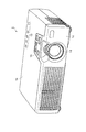
以下、本発明の第1実施形態について、図面を参照して説明する。図1及び図2は、本実施形態の電子機器としてのプロジェクタを示す斜視図であり、図1は、背面側から、図2は、前面側から見た図を示している。
(First embodiment)
Hereinafter, a first embodiment of the present invention will be described with reference to the drawings. 1 and 2 are perspective views showing a projector as an electronic apparatus according to the present embodiment. FIG. 1 is a view seen from the back side, and FIG. 2 is a view seen from the front side.
プロジェクタ1は、電子機器としての画像供給装置から供給される画像信号に基づいて光学像を形成し、この光学像をスクリーン等に投写することによって画像の表示を行うものである。
The
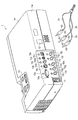
図1に示すように、プロジェクタ1の背面1aには、画像供給装置等の電子機器と、ケーブルを介して信号の伝達を行うためのインターフェイス部10が備えられており、インターフェイス部10には、ケーブルを接続するための接続端子として、複数の入力端子10a〜10eが備えられている。本実施形態のインターフェイス部10は、入力端子として、PC等から画像信号を入力するミニD−Sub15ピン端子10a、VTRやDVD再生装置等から画像信号を入力するためのS端子10b及びコンポジットビデオ信号用のピンジャック10c、音声信号を入力するミニジャック10d、PC等からプロジェクタ1を操作するための操作信号を入力するUSB(Universal Serial Bus)端子10eを備えている。また、インターフェイス部10の左側には、電源ケーブルを接続するためのインレット端子11が備えられ、インターフェイス部の右側には、非接触識別タグと非接触でデータの送受信が可能なアンテナ部12が備えられている。
As shown in FIG. 1, the
プロジェクタ1の上面1bでインターフェイス部10の近傍には、発光体としての5つのLED(Light Emitting Diode)13a〜13eからなるLED表示部13が備えられている。各LED13a〜13eは、それぞれ入力端子10a〜10eと対応付けられており、それぞれ対応する入力端子10a〜10eの近傍に配置されている。なお、LED表示部13は、インターフェイス部10と同じ面に配置されていてもよい。
In the vicinity of the
図2に示すように、プロジェクタ1は、その前面1cに投写レンズ14を備えており、前方に備えられる図示しないスクリーン等に光学像を投写することによって、画像を表示することができる。プロジェクタ1の上面1bには、操作部15が備えられている。操作部15には、電源のオンとオフとを切り換える電源スイッチや、表示画像の明るさ、コントラスト、或いはズーム状態等、プロジェクタ1の各種状態を操作するための操作スイッチ等が配置されている。
As shown in FIG. 2, the
図3は、プロジェクタ1の内部構成、及びプロジェクタ1を用いた画像表示システムを示すブロック図である。
FIG. 3 is a block diagram showing an internal configuration of the
図3に示すように、プロジェクタ1は、ケーブル2を介して画像供給装置3に接続され、画像供給装置3が出力する画像信号に基づいて、スクリーンSCに画像を表示可能になっており、プロジェクタ1と、ケーブル2と、画像供給装置3とは、電子機器システムとしての画像表示システム5を構成している。
As shown in FIG. 3, the
プロジェクタ1は、制御部20と、制御信号処理部21と、記憶部22と、通信部23と、LED制御部24と、検知部25と、画像信号処理部26と、OSD(オンスクリーンディスプレイ)処理部27とを備えている。前記各部20〜27は、バス28によって互いに接続されており、制御部20が、他の各部21〜27を制御して、プロジェクタ1の動作を統括する。
The
制御信号処理部21は、操作部15に接続されているとともに、リモコンRCとの間で赤外線による通信が可能になっており、さらに、前述したUSB端子10eを介してPCとの接続も可能になっている。制御信号処理部21は、操作部15や、リモコンRC、PCから操作信号を受信し、その旨を制御部20に通知すると、制御部20は、その操作信号に基づいてプロジェクタ1の各種状態の変更等を行う。
The control
記憶部22は、制御部20が実行する制御プログラムや、プロジェクタ1の各種状態を表す設定値等を記憶している。本実施形態では、さらに、プロジェクタ1に接続可能なケーブルの一覧情報(識別コードリスト)を記憶している。
The
通信部23は、アンテナ部12に備えられたコイルアンテナ23aに接続されており、電磁波を利用して通信を行う電磁誘導方式によって、通信可能範囲内に存在する非接触識別タグと非接触でデータ通信を行うことが可能になっている。利用する電磁波としては、例えば、135kHz以下、或いは、13.56MHz帯の電磁波を利用することが可能であり、本実施形態では、その通信可能範囲を、アンテナ部12から20〜30cm程度の範囲に設定している。
The
通信部23は、非接触識別タグにコマンドを表すデータを送信することによって、非接触識別タグに、コマンドに応じた動作を行わせることができる。非接触識別タグに対するコマンドの種類には、応答要求コマンドや、表示コマンド等がある。通信部23が応答要求コマンドを送信すると、これを受信したすべての非接触識別タグは、それぞれの識別情報を表すデータを通信部23に送信する。表示コマンドは、特定の非接触識別タグを指定して、非接触識別タグの表示部に所定の表示を行うためのものである。
The
LED制御部24は、LED表示部13の各LED13a〜13eの点灯及び消灯の切り換えを制御する。本実施形態では、ケーブル2を接続すべき入力端子に対応するLEDを点灯することによって、接続すべき入力端子をユーザに指示するものであり、LED制御部24及びLED表示部13は、ケーブル2の接続先を指示する指示部として機能する。
The
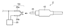
検知部25は、インターフェイス部10に備えられた各入力端子10a〜10eに接続されており、各入力端子10a〜10eにケーブル2が接続されているか否かの検知を行う。例えば、図4に示すように、ケーブル2側の1つの接触子45に対して、複数の接触子25a,25bを入力端子(例えば、10c)に備え、これらの接触子25a,25bが短絡しているか否かを検知すること等によって、ケーブル2が入力端子10cに接続されているか否かを検知することができる。また、ケーブル2のコネクタ部42が、互いに短絡された複数の接触子を備える場合には、入力端子側の前記接触子に対応する複数の接触子が短絡しているか否かを検知することによって、ケーブル2が入力端子10a〜10eに接続されているか否かを検知可能となる。
The
図3に戻って、画像供給装置3からケーブル2を介してインターフェイス部10に入力される画像信号は、画像信号処理部26に送られる。
Returning to FIG. 3, the image signal input to the
画像信号処理部26は、画像供給装置3から受信したアナログの画像信号をAD変換してデジタルの表示画像データを生成し、さらに、表示画像データにガンマ補正等の画像処理を施す。また、画像信号処理部26は、一時記憶のために、表示画像データを画像メモリ26aに書き込んだり、画像メモリ26aから表示画像データを読み出したりする機能を有している。画像処理が済んだ表示画像データは、OSD処理部27に供給される。
The image
OSD処理部27は、制御信号処理部21からの要求に応じて、プロジェクタ1の各種状態の確認や変更等を行うためのメニュー画像などを表すOSD画像データを、表示画像データに合成する処理を行う。
In response to a request from the control
メニュー画像を構成するグラフィックデータやフォントデータ等は、OSDメモリ27aに所定のフォーマットで記憶されている。メニュー画像を表示する際、OSD処理部27は、OSDメモリ27aからメニュー画像データを読み出してOSD画像データを生成し、このOSD画像データを画像信号処理部26から出力された表示画像データと合成して合成画像データを生成する。OSD処理部27から出力された合成画像データは、画像投写部29に供給される。なお、メニュー画像等を表示しない場合には、上記合成処理を行わないため、画像信号処理部26から出力される表示画像データが、そのまま画像投写部29に供給される。
Graphic data, font data, and the like constituting the menu image are stored in a predetermined format in the
画像投写部29は、光源と、液晶ライトバルブと、液晶ライトバルブ駆動部(いずれも図示せず)とを備えている。液晶ライトバルブ駆動部が、入力される画像データに応じて液晶ライトバルブを駆動することによって、光源から出射された光は変調され、光学像が形成される。この光学像を、投写レンズによってスクリーンSC上に投写することによって、スクリーンSC上に画像が表示される。ここで、画像信号処理部26と、画像投写部29と、投写レンズ14とは、入力した画像信号に応じてスクリーンSCに画像を表示する画像表示部として機能する。
The
また、プロジェクタ1には、インレット端子11を通じて外部電源を入力する電源部16が備えられており、操作部15に備えられた電源スイッチを操作することによって、前記各部に駆動電圧を供給し、プロジェクタ1が動作状態となる。
In addition, the
次に、ケーブル2について、図面を参照して説明する。
図5は、本実施形態のケーブル2を示す図であり、(a)は、ケーブル2の全体を示す図、(b)は、電子機器と接続するためのコネクタ部42を示す図である。
Next, the
5A and 5B are diagrams illustrating the
図5(a)に示すように、ケーブル2は、信号を伝達する導線部41と、導線部41の両端に備えられ、導線部41を2台の電子機器に接続するための2つのコネクタ部42とを備えている。各コネクタ部42には、プロジェクタ1の通信部23と非接触でデータ通信が可能な非接触識別タグ43と、表示部44とが備えられている。
As shown in FIG. 5A, the
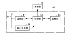
図6は、非接触識別タグ43と表示部44の回路構成を示すブロック図である。図6に示すように、非接触識別タグ43は、通信部51、制御部52、記憶部53、電力生成部54、コイルアンテナ55を含んだ構成になっている。
FIG. 6 is a block diagram illustrating a circuit configuration of the
通信部51は、記憶部53に記憶されたデータを、プロジェクタ1の通信部23に電磁誘導方式によって送信可能であるとともに、プロジェクタ1の通信部23から伝送されたデータを電磁誘導方式によって受信可能であり、これらの送受信は、コイルアンテナ55を介して行われる。
The
制御部52は、ロジック回路によって構成され、非接触識別タグ43の各部及び表示部44の動作を制御可能であり、データの送受信の制御や、表示部44への表示の制御を行う。
The
記憶部53は、フラッシュメモリや強誘電体メモリ(FeRAM)等の不揮発性のメモリからなっており、ケーブル2の識別情報を表すデータである識別コード等を記憶している。本実施形態では、識別コードとして、例えば、ケーブル2がミニD−Sub15ピン端子10aに接続するケーブルであれば、“MINID−SUB15”、S端子10bに接続するケーブルであれば、“S−VIDEO”のように、各ケーブルの種類を表す文字コードを記憶している。
The
表示部44には、例えば、電気泳動現象を利用した電気泳動表示装置を用いることができる。本実施形態では、表示のオンとオフの2つの状態を表すことが可能になっており、制御部52によって表示をオンにすると、図5(b)に示すように、表示部44に×印が表示される。
As the
なお、電気泳動表示装置は、表示画像保持性能(メモリ性)を有しているため、電圧の印加によって画像を一度表示させると、電圧の印加を解除した後も画像を保持することが可能になっている。ここで、電気泳動現象とは、液相分散媒中に帯電した微粒子(電気泳動粒子)を分散させた分散液に電界を印加したときに、微粒子がクーロン力により泳動する現象であり、液相分散媒と電気泳動粒子とに異なる着色をすることにより、電圧の印加方向に応じて表示内容を変更することができる。 In addition, since the electrophoretic display device has display image holding performance (memory property), if an image is displayed once by applying a voltage, the image can be held even after the application of the voltage is canceled. It has become. Here, the electrophoresis phenomenon is a phenomenon in which, when an electric field is applied to a dispersion liquid in which charged fine particles (electrophoretic particles) are dispersed in a liquid phase dispersion medium, the fine particles migrate due to Coulomb force. By differently coloring the dispersion medium and the electrophoretic particles, the display content can be changed in accordance with the voltage application direction.
電力生成部54は、プロジェクタ1の通信部23がデータを送信する際の搬送波(電磁波)から電力を生成して上記各部51,52,53,44に供給する。
The
上記のように構成されたケーブル2を、プロジェクタ1のアンテナ部12に近づけることによって、非接触識別タグ43が、プロジェクタ1の通信部23の通信可能範囲に入ると、プロジェクタ1は、非接触識別タグ43の記憶部53に記憶された識別コードを受信して、ケーブル2の種類を特定することが可能となる。
When the
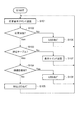
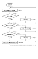
図7は、ケーブル2をプロジェクタ1に近づけた際のプロジェクタ1の動作を示すフローチャートである。プロジェクタ1に外部電源が供給された状態で、電源スイッチを操作し、プロジェクタ1が動作可能な状態になると、制御部20によって、下記の動作が開始される。
FIG. 7 is a flowchart showing the operation of the
図7に示すように、ステップS101では、制御部20は、通信部23によって応答要求コマンドを発信する。通信部23の通信可能範囲内に存在する非接触識別タグ43は、応答要求コマンドを受信すると、自己の記憶部53に記憶された識別コードを発信することによって応答する。
As shown in FIG. 7, in step S <b> 101, the
ステップS102では、非接触識別タグ43からの応答(識別コード)を受信したか否かを判断する。受信した場合にはステップS103に移行し、受信しなかった場合には、通信可能範囲内に非接触識別タグ43が存在しないと判断してステップS106に移行する。
In step S102, it is determined whether a response (identification code) from the
ステップS103では、受信した識別コードから、当該ケーブル2がプロジェクタ1に接続可能か否かを判断する。具体的には、受信した識別コードが記憶部22に記憶されている識別コードリストに含まれているか否かを判断し、含まれている、つまり、ケーブル2がプロジェクタ1に接続可能であればステップS104に移行し、含まれていない、つまり、接続不可能であればステップS107に移行する。
In step S103, it is determined from the received identification code whether the
ステップS104では、検知部25によって、応答したケーブル2が既に入力端子10a〜10eに接続されているか否かを判断する。既に接続されている場合には、ステップS108に移行し、接続されていない場合には、ステップS105に移行する。
In step S104, the
ステップS105では、LED制御部24によって、ケーブル2を接続すべき入力端子(入力端子10a〜10eのいずれか1つ)に対応するLED(LED13a〜13eのいずれか1つ)を点灯させる。これにより、ユーザは、ケーブル2を接続すべき入力端子を容易に特定することが可能となる。以降、ステップS101に戻って、上記動作を繰り返す。
In step S105, the LED (any one of the
ここで、ステップS102において、非接触識別タグ43からの応答がなく、ステップS106に移行した場合で、既に点灯しているLED13a〜13eがある場合には、そのLEDを消灯する。
Here, in step S102, when there is no response from the
また、ステップS104において、応答したケーブル2が既に入力端子10a〜10eに接続されていると判断し、ステップS108に移行した場合で、前記入力端子に対応するLEDが点灯している場合には、そのLEDを消灯する。
In step S104, when it is determined that the responding
一方、ステップS103において、ケーブル2がプロジェクタ1に接続不可能と判断され、ステップS107に移行した場合には、表示コマンドとケーブル2の識別コードとを発信し、当該ケーブル2の表示部44に使用不可である旨を表示させる。
On the other hand, if it is determined in step S103 that the
図8は、ケーブル2をプロジェクタ1に近づけた際のケーブル2の動作を示すフローチャートである。
FIG. 8 is a flowchart showing the operation of the
まず、ケーブル2の非接触識別タグ43が、コイルアンテナ55で所定の電磁波を受信すると、電力生成部54は、各部の動作に必要な動作電圧を生成し、各部に供給する。これにより、非接触識別タグ43及び表示部44は、動作可能状態となってステップS111に移行する。
First, when the
ステップS111では、電磁波に含まるデータを通信部51で受信し、このデータがプロジェクタ1の通信部23から送信されたコマンドであるか否かを判断する。コマンドである場合には、ステップS112に移行し、コマンドでない場合には、ステップS111を繰り返す。
In step S111, data included in the electromagnetic wave is received by the
ステップS112では、受信したコマンドが応答要求コマンドであるか否かを判断する。応答要求コマンドであれば、ステップS113に移行し、他のコマンドであれば、ステップS114に移行する。 In step S112, it is determined whether the received command is a response request command. If it is a response request command, the process proceeds to step S113, and if it is another command, the process proceeds to step S114.
ステップS113に移行した場合には、応答要求コマンドに応答するため、記憶部53に記憶された識別コードをプロジェクタ1に対して送信し、ステップS111に戻る。
When the process proceeds to step S113, in order to respond to the response request command, the identification code stored in the
ステップS114に移行した場合には、受信したコマンドが当該ケーブル2に対する表示コマンドであるか否かを判断する。具体的には、受信したコマンドが表示コマンドであり、かつ表示コマンドと同時に送信された識別コードが記憶部53に記憶されている自己の識別コードと一致するか否かを判断し、一致する場合には、ステップS115に移行し、そうでなければステップS111に戻る。
When the process proceeds to step S114, it is determined whether or not the received command is a display command for the
ステップS115では、制御部52が表示部44を制御して、表示部をオンの状態に設定する。これにより、図5(b)にしめすように、ケーブル2の表示部44に×印が表示され、ユーザは、当該ケーブル2がプロジェクタ1に接続不可能であることを認識することができる。その後、ステップS111に戻って、上記動作を繰り返す。
In step S115, the
以上説明したように、本実施形態のプロジェクタ1、ケーブル2、及び画像表示システム5によれば、以下の効果を得ることができる。
As described above, according to the
(1)本実施形態の画像表示システム5によれば、ケーブル2が、ケーブル2の種類を表す識別コードを記憶した記憶部53と、識別コードをプロジェクタ1に送信可能な通信部51を備え、プロジェクタ1が、この識別コードを非接触で受信可能な通信部23と、各入力端子10a〜10eに対応するLED13a〜13eと、LED13a〜13eの点灯状態を制御するLED制御部24とを有している。このため、プロジェクタ1にケーブル2を接続する際に、プロジェクタ1は、通信部23で識別コードを読み取ることによって、接続しようとしているケーブル2の種類を知ることが可能となり、複数の入力端子10a〜10eの中から当該ケーブル2を接続すべき入力端子をLED13a〜13eによって指示することが可能となる。この結果、ケーブル2を接続すべき入力端子を特定することが容易になる。
(1) According to the image display system 5 of the present embodiment, the
(2)本実施形態のプロジェクタ1によれば、ケーブル2の通信部51から送信された識別コードを、非接触で受信可能な通信部23と、受信した識別コードに応じてケーブル2を接続すべき入力端子を指示可能なLED13a〜13eと、LED13a〜13eの点灯状態を制御するLED制御部24とを有している。このため、プロジェクタ1にケーブル2を接続する際に、プロジェクタ1は、ケーブルの種類を表す識別コードを通信部23によって読み取り、複数の入力端子10a〜10eの中から、当該ケーブル2を接続すべき入力端子をLED13a〜13eで指示することが可能となる。この結果、ケーブル2を接続すべき入力端子を特定することが容易になる。
(2) According to the
(3)本実施形態のプロジェクタ1によれば、各入力端子10a〜10eに対応するLED13a〜13eが備えられ、LED13a〜13eの点灯状態によって接続すべき入力端子を指示するため、接続すべき入力端子を特定する際の視認性が向上する。
(3) According to the
(4)本実施形態のプロジェクタ1によれば、入力端子10a〜10eにケーブル2が接続されているか否かを検知可能な検知部25を備えており、ケーブル2の接続を検知することにより、LED13a〜13eを消灯するようにしているため、LED13a〜13eの点灯に要する消費電力を低減することが可能となる。
(4) According to the
(5)本実施形態のケーブル2によれば、ケーブル2の種類を表す識別コードを記憶した記憶部53と、識別コードを非接触で送信可能な通信部51とを備えているため、プロジェクタ1に対してケーブル2を接続する際に、プロジェクタ1が、当該ケーブル2の種類を知ることが可能となり、接続すべき入力端子の指示を行うことが可能となる。この結果、ケーブルを接続すべき接続端子を特定することが容易になる。
(5) According to the
(6)本実施形態のケーブル2によれば、ケーブル2が使用不可能である場合にプロジェクタ1が発信する表示コマンドを受信した際に、表示部44によって、使用不可能であることを表示可能であるため、プロジェクタ1に対してケーブル2の接続を試みる前に、当該ケーブル2の使用可否を知ることが可能となる。
(6) According to the
(第2実施形態)
本発明の第2実施形態を、図面を参照して説明する。図9は、第2実施形態のプロジェクタにケーブルを近づけた際のプロジェクタ1の動作を示すフローチャートであり、図10は、その説明図である。本実施形態のプロジェクタ1は、第1実施形態のLED制御部24及びLED表示部13に代わって、投写画像によって接続すべき入力端子の指示を行うものである。また、プロジェクタ1の記憶部22には、プロジェクタ1のインターフェイス部10の実写画像を表す画像データが記憶されている。
(Second Embodiment)
A second embodiment of the present invention will be described with reference to the drawings. FIG. 9 is a flowchart showing the operation of the
図9に示すように、プロジェクタ1は、ステップS105を除いて第1実施形態と同じ動作を行うものであり、ステップS101〜S104において、応答要求コマンドに対して応答したケーブル2が、プロジェクタ1に対応可能で、かつ未接続の状態だった場合に、ステップS105aに移行する。
As shown in FIG. 9, the
ステップS105aでは、制御部20が、記憶部22からインターフェイス部10の実写画像を表す画像データを読み出して、これをOSD処理部27に供給する。さらに、OSD処理部27は、「このコネクタに接続してください。」というメッセージと、ケーブル2を接続すべき入力端子を指し示す矢印とを、前記画像データに合成し、画像投写部29によって、合成画像をスクリーンSC等に投写する(図10参照)。これにより、ユーザは、投写された画像を見ることによって、ケーブル2を接続すべき入力端子を容易に特定することが可能となる。即ち、インターフェイス部10の実写画像を記憶する記憶部22と、メッセージや矢印を合成するOSD処理部27と、画像を投写する画像投写部29とが本実施形態の指示部を構成する。以降、ステップS101に戻って、上記動作を繰り返す。
In step S <b> 105 a, the
ここで、本実施形態のステップS103において、ケーブル2が接続不可能(非対応)である場合に、「使用できないケーブルです。」等のメッセージをOSD処理部27によって付加するようにすれば、ケーブル2に表示部44を備えなくとも、ケーブル2の使用可否を容易に認識することができるようになる。
Here, in step S103 of the present embodiment, when the
以上説明したように、本実施形態のプロジェクタ1によれば、前記実施形態の効果に加えて、以下の効果を得ることができる。
As described above, according to the
本実施形態のプロジェクタ1によれば、プロジェクタ1がスクリーンSC等に表示する画像によって、ケーブル2を接続すべき入力端子を指示するため、実写画像や文字等を用いた詳細な指示が可能となるうえ、ケーブル2の接続先を指示するためのみに用いられるLED等を設ける必要がない。
According to the
(第3実施形態)
本発明の第3実施形態を、図面を参照して説明する。図11は、本実施形態のプロジェクタを背面側から見た斜視図である。
(Third embodiment)
A third embodiment of the present invention will be described with reference to the drawings. FIG. 11 is a perspective view of the projector according to the present embodiment as viewed from the back side.
図11に示すように、本実施形態のインターフェイス部10には、第1の実施形態のインターフェイス部10が備える入力端子に加えて、コンポーネントビデオ信号を入力するための3つで1組のピンジャック(入力端子)10f,10g,10hと、音声信号を入力するための2つで1組のピンジャック(入力端子)10i,10jとを備えている。また、接続先を指示するためのLED13a〜13jが、それぞれ入力端子10a〜10jの上方に備えられている。
As shown in FIG. 11, the
ここで、本実施形態の通信部23は、通信可能範囲をアンテナ部12から2cm程度のごく近距離に制限しており、入力端子10a〜10jに接続されたケーブル2の非接触識別タグ43とは通信できないようになっている。
Here, the
また、本実施形態のプロジェクタ1は、ケーブル2が接続されたか否かを検知可能な検知部25を備えていない。さらに、非接触識別タグ43をアンテナ部12のごく近傍に近づけて、LEDを一度点灯させると、非接触識別タグ43が通信可能範囲外となった後も、所定の時間(例えば、10秒)経過するまで点灯状態を維持するようになっている。
Further, the
本実施形態のように、複数個で1組の入力端子に接続するためのケーブルとして、複数本のケーブルが一体となったものが用いられることがある。図11に示した3本のケーブル2a,2b,2cは、コンポーネントビデオ信号入力用のケーブルであり、3本が束ねられて一体となっている。各ケーブル2a,2b,2cのコネクタ部42には、それぞれに非接触識別タグ43が備えられており、各非接触識別タグ43が有する記憶部53には、それぞれ異なる識別コードが記憶されている。
As in the present embodiment, as a plurality of cables for connecting to a set of input terminals, a cable in which a plurality of cables are integrated may be used. The three
このケーブル2a,2b,2cを接続する際には、3本のうちの1本(例えばケーブル2a)のコネクタ部42をアンテナ部12のごく近傍に近づけることで、プロジェクタ1は、ケーブル2aの非接触識別タグ43と通信可能となる。このとき、通信部23の通信可能範囲をごく近距離に制限しているため、他の2本のケーブル2b、2cの非接触識別タグ43と通信可能になることはない。
When connecting the
プロジェクタ1が、ケーブル2aを接続すべきピンジャック(例えば、入力端子10f)に対応するLED13fを点灯させると、ユーザは、これに従って、ピンジャック10fにケーブル2aを接続しようとして、ケーブル2aのコネクタ部42をピンジャック10fに近づける。このとき、非接触識別タグ43は、通信可能範囲を外れることになるが、LED13fが所定の時間点灯状態を維持しているため、LED13fの点灯による指示に従って、ケーブル2aを接続することができる。引き続いて、ケーブル2b、2cについても、同様の作業を行うことで、すべてのケーブル2a,2b,2cを正しい位置に接続することが可能となる。
When the
以上説明したように、本実施形態のプロジェクタ1によれば、前記実施形態の効果に加えて、以下の効果を得ることができる。
As described above, according to the
(1)本実施形態によれば、通信部23の通信可能範囲をごく近距離に制限しているため、複数本のケーブル2a,2b,2cが一体となったケーブルを接続する際に、各ケーブルのコネクタ部42に備えられた非接触識別タグ43と同時に通信可能となるのを避けることができる。この結果、プロジェクタ1は、複数本のケーブル2a,2b,2cのうち、どのケーブルを接続しようとしているかを特定することが可能となり、接続すべき入力端子を適切に指示することが可能となる。
(1) According to the present embodiment, since the communicable range of the
(2)本実施形態によれば、ケーブル2が入力端子に接続された状態では、通信部23は、ケーブル2の非接触識別タグ43と通信することができず、さらに、非接触識別タグ43が、通信部23の通信可能範囲から外れた後も、所定の時間LEDの点灯状態を維持するようにしている。このため、入力端子の接続状態を検知可能な検知部25を備えなくとも、ケーブル2を接続し終わるまで、ケーブル2を接続すべき入力端子を指示することが可能となるうえ、LEDが点灯し続けることがないため、消費電力を低減することが可能となる。
(2) According to the present embodiment, the
(変形例)
本発明の実施形態は、以下のように変更してもよい。
(Modification)
The embodiment of the present invention may be modified as follows.
・前記第3実施形態において、複数本のケーブル2a,2b,2cと同時に通信可能となるのを避けるために、通信部23の通信可能範囲を制限するかわりに、ケーブル2a,2b,2cのそれぞれに、プロジェクタ1との通信を遮断する通信遮断部を備えるようにしてもよい。
In the third embodiment, instead of limiting the communicable range of the
図12は、コネクタ部42に通信遮断部を備えたケーブルの説明図である。図12(a)、(b)に示すように、ケーブル2のコネクタ部42には、通信遮断部として、非接触識別タグ43よりも大きな開口部61aを有する金属管61が回動可能に備えられている。図12(a)に示すように、この金属管61によって非接触識別タグ43が被覆された状態では、非接触識別タグ43のコイルアンテナ55がシールドされて、外部との通信が遮断される。また、図12(b)に示すように、金属管61を回動させて開口部61aと非接触識別タグ43の位置を一致させると、シールドが解除され、外部との通信が可能になる。
FIG. 12 is an explanatory diagram of a cable provided with a communication blocking unit in the
これによれば、一体となった3本のケーブル2a,2b,2cのうち、接続しようとする1本のケーブルのみを通信可能な状態とし、さらに、接続後に通信を遮断することによって、3本のケーブルが同時に通信可能となるのを防ぐことが可能となる。この結果、複数本のケーブル2a,2b,2cと同時に通信可能となるのを避けるために、通信部23の通信可能範囲を制限する必要がなくなり、非接触識別タグ43をアンテナ部12のごく近傍に近づける必要がなくなる。
According to this, among the three
・前記第1〜第3実施形態のように、プロジェクタ1の通信部23が、常時、応答要求コマンドを発信して、通信可能範囲内の非接触識別タグ43の存在を監視する代わりに、ユーザが操作部15等を操作することによって、非接触識別タグ43の監視を開始するようにしてもよい。さらに、この場合において、検知部25によってケーブル2が接続されたことを検知した際に、非接触識別タグ43の監視を中止するようにしてもよい。
As in the first to third embodiments, instead of the
これによれば、ケーブル2の接続を行う必要があるときのみに、非接触識別タグ43の監視を行うため、消費電力を低減することが可能となる。
According to this, since the
・前記第1及び第2実施形態において、検知部25が画像信号を入力するための入力端子10a〜10cのいずれにもケーブル2が接続されていないことを検知したときに、ケーブルの接続を促すメッセージをスクリーンSC等に表示するとともに、非接触識別タグ43の監視を開始するようにしてもよい。さらに、この場合において、検知部25によってケーブル2が接続されたことを検知した際に、非接触識別タグ43の監視を中止するようにしてもよい。
In the first and second embodiments, when the
これによれば、ケーブル2の接続をユーザに促すことが可能となるうえ、ケーブル2の接続を行う必要があるときのみに、非接触識別タグ43の監視を行うため、消費電力を低減することが可能となる。
According to this, it is possible to prompt the user to connect the
・前記第1〜第3実施形態において、プロジェクタ1が動作状態か否かに拘わらず、少なくとも通信部23を常時動作させ、常に非接触識別タグ43の監視をするようにしてもよい。この場合において、プロジェクタ1が非動作の状態で、通信部23が非接触識別タグ43からの応答を受信した場合に、通信部23が電源部16に信号を発信し、信号を受信した電源部16が、駆動電圧を各部に供給することによってプロジェクタ1の動作を開始させて、ケーブル2の接続先を指示するようにしてもよい。或いは、外部電源とは異なる電源をプロジェクタ1に備え、外部電源が供給されていない状態でも、通信部23、LED制御部24及びLED表示部13を動作可能な状態とすることによって、外部電源の供給の有無に拘わらず、ケーブル2の接続先を指示できるようにしてもよい。
In the first to third embodiments, regardless of whether or not the
・前記第1及び第2実施形態において、検知部25は、必須の構成要件ではなく、省略可能である。検知部25を省略する場合には、ケーブル2を入力端子10a〜10eに接続している期間中、対応するLEDを常に点灯させるようにしてもよいし、第3実施形態と同様、所定の時間のみ点灯を維持するようにしてもよい。
In the first and second embodiments, the
・前記第1〜第3実施形態において、プロジェクタ1のインターフェイス部10に、複数個で1組の入力端子が複数組備えられている場合で、前記入力端子に接続可能な1組のケーブルのうち、最初の1本のケーブルを接続する際には、当該ケーブルが接続可能な各組の接続端子を指示し、2本目以降のケーブルを接続する際には、最初の1本が接続された接続端子と同組の接続端子を指示するようにするのが望ましい。
In the first to third embodiments, the
・本発明の実施形態は、プロジェクタ1に限定されず、他の電子機器にも適用可能である。また、ケーブルが接続される接続端子は、入力端子に限られず、出力端子や入出力端子、或いは、電源ケーブルを接続するためのインレット端子等、他の接続端子にも適用可能である。
The embodiment of the present invention is not limited to the
1…電子機器としてのプロジェクタ、2…ケーブル、3…電子機器としての画像供給装置、5…電子機器システムとしての画像表示システム、10…インターフェイス部、10a〜10j…入力端子、12…アンテナ部、13…指示部を構成するLED表示部、13a〜13j…指示部を構成するLED、14…画像表示部を構成する投写レンズ、15…操作部、16…電源部、20…制御部、21…制御信号処理部、22…記憶部、23…第2の通信部としての通信部、23a…コイルアンテナ、24…指示部を構成するLED制御部、25…検知部、26…画像表示部を構成する画像信号処理部、27…OSD処理部、28…バス、29…画像表示部を構成する画像投写部、41…導線部、42…コネクタ部、43…非接触識別タグ、44…表示部、51…第1の通信部としての通信部、52…制御部、53…記憶部、54…電力生成部、55…コイルアンテナ。
DESCRIPTION OF
Claims (8)
前記ケーブルは、当該ケーブルの種類を識別可能な識別情報を記憶する記憶部と、前記識別情報を非接触で送信可能な第1の通信部とを備え、
前記複数の電子機器の少なくとも1つは、前記ケーブルを接続可能な複数の接続端子と、前記識別情報を非接触で受信可能な第2の通信部と、前記識別情報に応じて前記ケーブルを接続すべき接続端子を指示する指示部とを備えたことを特徴とする電子機器システム。 An electronic device system comprising a plurality of electronic devices and a cable for connecting the plurality of electronic devices,
The cable includes a storage unit that stores identification information that can identify the type of the cable, and a first communication unit that can transmit the identification information in a contactless manner.
At least one of the plurality of electronic devices connects the cable according to the identification information, a plurality of connection terminals to which the cable can be connected, a second communication unit capable of receiving the identification information in a contactless manner, An electronic device system comprising: an instruction unit that instructs a connection terminal to be connected.
前記ケーブルから送信された識別情報を、非接触で受信可能な第2の通信部と、
前記識別情報に応じて前記ケーブルを接続すべき接続端子を指示する指示部と、
を備えたことを特徴とする電子機器。 A plurality of connection terminals to which cables for connecting to other electronic devices can be connected;
A second communication unit capable of receiving the identification information transmitted from the cable in a contactless manner;
An instruction unit for instructing a connection terminal to which the cable is to be connected according to the identification information;
An electronic device characterized by comprising:
当該ケーブルの種類を識別可能な識別情報を記憶する記憶部と、
前記識別情報を非接触で送信可能な第1の通信部と、
を備え、
前記電子機器の少なくとも一方に、前記識別情報を送信可能であることを特徴とするケーブル。 A cable for connecting a plurality of electronic devices,
A storage unit for storing identification information capable of identifying the type of the cable;
A first communication unit capable of transmitting the identification information in a contactless manner;
With
A cable characterized in that the identification information can be transmitted to at least one of the electronic devices.
The cable according to claim 7, wherein the first data communication unit can transmit and receive data without contact, and can change a display state in accordance with data received by the first data communication unit. A cable characterized by having a display section.
Priority Applications (1)
| Application Number | Priority Date | Filing Date | Title |
|---|---|---|---|
| JP2004222989A JP2006039448A (en) | 2004-07-30 | 2004-07-30 | Electronic apparatus, cable, and electronic apparatus system |
Applications Claiming Priority (1)
| Application Number | Priority Date | Filing Date | Title |
|---|---|---|---|
| JP2004222989A JP2006039448A (en) | 2004-07-30 | 2004-07-30 | Electronic apparatus, cable, and electronic apparatus system |
Publications (2)
| Publication Number | Publication Date |
|---|---|
| JP2006039448A true JP2006039448A (en) | 2006-02-09 |
| JP2006039448A5 JP2006039448A5 (en) | 2007-06-28 |
Family
ID=35904479
Family Applications (1)
| Application Number | Title | Priority Date | Filing Date |
|---|---|---|---|
| JP2004222989A Withdrawn JP2006039448A (en) | 2004-07-30 | 2004-07-30 | Electronic apparatus, cable, and electronic apparatus system |
Country Status (1)
| Country | Link |
|---|---|
| JP (1) | JP2006039448A (en) |
Cited By (5)
| Publication number | Priority date | Publication date | Assignee | Title |
|---|---|---|---|---|
| JP2007264228A (en) * | 2006-03-28 | 2007-10-11 | Seiko Epson Corp | Projector, display image adjusting method, program for performing same method, and recording medium with recorded program thereon |
| JP2008139607A (en) * | 2006-12-04 | 2008-06-19 | Seiko Epson Corp | Projector, projection system and informing method |
| JP2012118559A (en) * | 2012-01-20 | 2012-06-21 | Seiko Epson Corp | Projection system and notification method |
| JPWO2011111122A1 (en) * | 2010-03-12 | 2013-06-27 | 富士通株式会社 | Mounting work support device, method, and program |
| WO2016166868A1 (en) * | 2015-04-16 | 2016-10-20 | 日立マクセル株式会社 | Projection-type image display apparatus and method for displaying information in projection-type image display apparatus |
-
2004
- 2004-07-30 JP JP2004222989A patent/JP2006039448A/en not_active Withdrawn
Cited By (7)
| Publication number | Priority date | Publication date | Assignee | Title |
|---|---|---|---|---|
| JP2007264228A (en) * | 2006-03-28 | 2007-10-11 | Seiko Epson Corp | Projector, display image adjusting method, program for performing same method, and recording medium with recorded program thereon |
| JP4561668B2 (en) * | 2006-03-28 | 2010-10-13 | セイコーエプソン株式会社 | Projector, display image adjustment method, program for executing the method, and recording medium storing the program |
| JP2008139607A (en) * | 2006-12-04 | 2008-06-19 | Seiko Epson Corp | Projector, projection system and informing method |
| JPWO2011111122A1 (en) * | 2010-03-12 | 2013-06-27 | 富士通株式会社 | Mounting work support device, method, and program |
| JP2012118559A (en) * | 2012-01-20 | 2012-06-21 | Seiko Epson Corp | Projection system and notification method |
| WO2016166868A1 (en) * | 2015-04-16 | 2016-10-20 | 日立マクセル株式会社 | Projection-type image display apparatus and method for displaying information in projection-type image display apparatus |
| US10564535B2 (en) | 2015-04-16 | 2020-02-18 | Maxell, Ltd. | Projection type image display apparatus and information display method on projection type image display apparatus |
Similar Documents
| Publication | Publication Date | Title |
|---|---|---|
| CN102722289B (en) | Image supply device, image display system, method of controlling image supply device | |
| US8619193B2 (en) | Communication apparatus, control method, and computer readable recording medium | |
| KR20110108283A (en) | Handwriting data generating system, handwriting data generating method and computer readable recording medium having a computer program | |
| TW201636774A (en) | Display device, terminal device, and display system | |
| US20090251621A1 (en) | Image display system and image display apparatus | |
| CN105161043A (en) | Display device, display system with multiple display devices and method for controlling display system | |
| KR20180033681A (en) | Display device and power controlling method thereof | |
| JP6094046B2 (en) | Projection type display device, display system, and display method | |
| CN104012105A (en) | Display device, display control method, portable terminal device, and program | |
| US20110032433A1 (en) | Connection state display controller, content processor, content processing system, connection state display control method, its program and recording medium recording the program | |
| US9684390B2 (en) | Image display device, projector, and control method for image display device | |
| JP2006039448A (en) | Electronic apparatus, cable, and electronic apparatus system | |
| CN104683717A (en) | Both-direction display method and both-direction display apparatus | |
| US8780095B2 (en) | Projector and control method | |
| US9905141B2 (en) | Image output apparatus and computer-readable recording medium | |
| JP2009288753A (en) | Projector and method of controlling the same | |
| JP7069922B2 (en) | Display device, display system and control method of display device | |
| JP5171428B2 (en) | Electronics | |
| CN115834846A (en) | Image display method and projector | |
| CN100405284C (en) | Display system | |
| KR101586149B1 (en) | Data cable apparatus and system including the same | |
| JP2018055409A (en) | Electronic device, communication system, and electronic device control method | |
| JP6992325B2 (en) | Communication system, terminal device, and control method of communication system | |
| JP2010200223A (en) | Electronic apparatus, method of controlling electronic apparatus, remote controller, method of controlling remote controller and program | |
| JP2008192018A (en) | Radio adapter for image display device |
Legal Events
| Date | Code | Title | Description |
|---|---|---|---|
| RD04 | Notification of resignation of power of attorney |
Free format text: JAPANESE INTERMEDIATE CODE: A7424 Effective date: 20070403 |
|
| A521 | Written amendment |
Free format text: JAPANESE INTERMEDIATE CODE: A523 Effective date: 20070509 |
|
| A621 | Written request for application examination |
Free format text: JAPANESE INTERMEDIATE CODE: A621 Effective date: 20070509 |
|
| A761 | Written withdrawal of application |
Free format text: JAPANESE INTERMEDIATE CODE: A761 Effective date: 20071228 |