JP2006032017A - Lamp operation control device and its method - Google Patents
Lamp operation control device and its method Download PDFInfo
- Publication number
- JP2006032017A JP2006032017A JP2004206263A JP2004206263A JP2006032017A JP 2006032017 A JP2006032017 A JP 2006032017A JP 2004206263 A JP2004206263 A JP 2004206263A JP 2004206263 A JP2004206263 A JP 2004206263A JP 2006032017 A JP2006032017 A JP 2006032017A
- Authority
- JP
- Japan
- Prior art keywords
- lamp
- discharge lamp
- operation control
- pulse
- voltage
- Prior art date
- Legal status (The legal status is an assumption and is not a legal conclusion. Google has not performed a legal analysis and makes no representation as to the accuracy of the status listed.)
- Granted
Links
- 238000000034 method Methods 0.000 title claims abstract description 23
- 238000001514 detection method Methods 0.000 abstract description 7
- 230000008569 process Effects 0.000 abstract description 4
- 238000012545 processing Methods 0.000 description 25
- 230000008859 change Effects 0.000 description 14
- 238000003860 storage Methods 0.000 description 11
- 238000010586 diagram Methods 0.000 description 6
- 230000007774 longterm Effects 0.000 description 4
- 238000004364 calculation method Methods 0.000 description 3
- 239000004973 liquid crystal related substance Substances 0.000 description 3
- 238000005259 measurement Methods 0.000 description 3
- 239000003990 capacitor Substances 0.000 description 2
- 238000006243 chemical reaction Methods 0.000 description 2
- 230000000694 effects Effects 0.000 description 2
- 230000006698 induction Effects 0.000 description 2
- 238000004519 manufacturing process Methods 0.000 description 2
- 230000002123 temporal effect Effects 0.000 description 2
- 101100162182 Caenorhabditis elegans adt-1 gene Proteins 0.000 description 1
- 101100108263 Caenorhabditis elegans adt-2 gene Proteins 0.000 description 1
- 101100369818 Chlamydia pneumoniae tlcA gene Proteins 0.000 description 1
- 101100369822 Chlamydia pneumoniae tlcB gene Proteins 0.000 description 1
- 230000009471 action Effects 0.000 description 1
- 238000007796 conventional method Methods 0.000 description 1
- 230000007423 decrease Effects 0.000 description 1
- 238000010891 electric arc Methods 0.000 description 1
- 238000005516 engineering process Methods 0.000 description 1
- 230000001678 irradiating effect Effects 0.000 description 1
- QSHDDOUJBYECFT-UHFFFAOYSA-N mercury Chemical compound [Hg] QSHDDOUJBYECFT-UHFFFAOYSA-N 0.000 description 1
- 229910052753 mercury Inorganic materials 0.000 description 1
- 229910001507 metal halide Inorganic materials 0.000 description 1
- 150000005309 metal halides Chemical class 0.000 description 1
- 238000012986 modification Methods 0.000 description 1
- 230000004048 modification Effects 0.000 description 1
- 238000012544 monitoring process Methods 0.000 description 1
- 230000003287 optical effect Effects 0.000 description 1
- 230000004044 response Effects 0.000 description 1
- 238000004904 shortening Methods 0.000 description 1
- 230000036962 time dependent Effects 0.000 description 1
Images


Classifications
-
- H—ELECTRICITY
- H05—ELECTRIC TECHNIQUES NOT OTHERWISE PROVIDED FOR
- H05B—ELECTRIC HEATING; ELECTRIC LIGHT SOURCES NOT OTHERWISE PROVIDED FOR; CIRCUIT ARRANGEMENTS FOR ELECTRIC LIGHT SOURCES, IN GENERAL
- H05B41/00—Circuit arrangements or apparatus for igniting or operating discharge lamps
- H05B41/14—Circuit arrangements
- H05B41/26—Circuit arrangements in which the lamp is fed by power derived from dc by means of a converter, e.g. by high-voltage dc
- H05B41/28—Circuit arrangements in which the lamp is fed by power derived from dc by means of a converter, e.g. by high-voltage dc using static converters
- H05B41/288—Circuit arrangements in which the lamp is fed by power derived from dc by means of a converter, e.g. by high-voltage dc using static converters with semiconductor devices and specially adapted for lamps without preheating electrodes, e.g. for high-intensity discharge lamps, high-pressure mercury or sodium lamps or low-pressure sodium lamps
- H05B41/2885—Static converters especially adapted therefor; Control thereof
-
- H—ELECTRICITY
- H05—ELECTRIC TECHNIQUES NOT OTHERWISE PROVIDED FOR
- H05B—ELECTRIC HEATING; ELECTRIC LIGHT SOURCES NOT OTHERWISE PROVIDED FOR; CIRCUIT ARRANGEMENTS FOR ELECTRIC LIGHT SOURCES, IN GENERAL
- H05B41/00—Circuit arrangements or apparatus for igniting or operating discharge lamps
- H05B41/14—Circuit arrangements
- H05B41/26—Circuit arrangements in which the lamp is fed by power derived from dc by means of a converter, e.g. by high-voltage dc
- H05B41/28—Circuit arrangements in which the lamp is fed by power derived from dc by means of a converter, e.g. by high-voltage dc using static converters
- H05B41/288—Circuit arrangements in which the lamp is fed by power derived from dc by means of a converter, e.g. by high-voltage dc using static converters with semiconductor devices and specially adapted for lamps without preheating electrodes, e.g. for high-intensity discharge lamps, high-pressure mercury or sodium lamps or low-pressure sodium lamps
- H05B41/292—Arrangements for protecting lamps or circuits against abnormal operating conditions
- H05B41/2928—Arrangements for protecting lamps or circuits against abnormal operating conditions for protecting the lamp against abnormal operating conditions
-
- H—ELECTRICITY
- H05—ELECTRIC TECHNIQUES NOT OTHERWISE PROVIDED FOR
- H05B—ELECTRIC HEATING; ELECTRIC LIGHT SOURCES NOT OTHERWISE PROVIDED FOR; CIRCUIT ARRANGEMENTS FOR ELECTRIC LIGHT SOURCES, IN GENERAL
- H05B41/00—Circuit arrangements or apparatus for igniting or operating discharge lamps
- H05B41/14—Circuit arrangements
- H05B41/36—Controlling
- H05B41/38—Controlling the intensity of light
- H05B41/39—Controlling the intensity of light continuously
- H05B41/392—Controlling the intensity of light continuously using semiconductor devices, e.g. thyristor
- H05B41/3921—Controlling the intensity of light continuously using semiconductor devices, e.g. thyristor with possibility of light intensity variations
-
- Y—GENERAL TAGGING OF NEW TECHNOLOGICAL DEVELOPMENTS; GENERAL TAGGING OF CROSS-SECTIONAL TECHNOLOGIES SPANNING OVER SEVERAL SECTIONS OF THE IPC; TECHNICAL SUBJECTS COVERED BY FORMER USPC CROSS-REFERENCE ART COLLECTIONS [XRACs] AND DIGESTS
- Y02—TECHNOLOGIES OR APPLICATIONS FOR MITIGATION OR ADAPTATION AGAINST CLIMATE CHANGE
- Y02B—CLIMATE CHANGE MITIGATION TECHNOLOGIES RELATED TO BUILDINGS, e.g. HOUSING, HOUSE APPLIANCES OR RELATED END-USER APPLICATIONS
- Y02B20/00—Energy efficient lighting technologies, e.g. halogen lamps or gas discharge lamps
Abstract
Description
本発明は、例えば、液晶プロジェクタ等の投射型ディスプレイにおいて使用される高圧放電ランプのための作動電圧/電流を供給するための装置及びその方法に関し、特に、当該高圧放電ランプにおける経時変化にも拘わらず安定した光(出力)が得られるランプ作動制御装置及びその方法に関するものである。 The present invention relates to an apparatus and method for supplying an operating voltage / current for a high-pressure discharge lamp used in a projection display such as a liquid crystal projector, and more particularly to a change over time in the high-pressure discharge lamp. The present invention relates to a lamp operation control device and a method thereof that can obtain stable light (output).
従来、液晶プロジェクタ等の投射型ディスプレイの光源としては、変換効率が高く、かつ、点光源に近い光が得やすいという理由から、メタルハライドランプや高圧水銀ランプ等、所謂、高圧放電ランプが使用されている。また、かかる高圧放電ランプの点灯には、点灯に必要な電圧及び電流を供給するため、専用の放電ランプ点灯装置が使用されている。近年では、かかる放電ランプ点灯装置には、例えば、下記の特許文献1、特許文献2に記載の様に、消費電力を演算し、電力を一定に保つために、マイコンにより放電ランプ点灯装置の制御を行う方式が既に提案されている。
Conventionally, so-called high-pressure discharge lamps such as metal halide lamps and high-pressure mercury lamps have been used as light sources for projection-type displays such as liquid crystal projectors because of their high conversion efficiency and the ability to easily obtain light close to point light sources. Yes. Further, a dedicated discharge lamp lighting device is used for lighting such a high-pressure discharge lamp in order to supply a voltage and a current necessary for lighting. In recent years, such discharge lamp lighting devices include, for example, control of the discharge lamp lighting device by a microcomputer in order to calculate power consumption and keep the power constant as described in
なお、かかる高圧放電ランプの構造は、例えば、以下の特許文献3等により既に知られている。そして、かかる高圧放電ランプでは、例えば、以下の特許文献4〜特許文献7によって既に知られるように、高圧放電ランプ交流の矩形状の作動電圧及び作動電流を加えると共に、放電に伴う電極の消耗によるアーク電圧の変動やフリッカ(チラツキ)の発生を低減すること等を目的として、交互にその極性を変化する矩形又は所定の形状を有するランプ電流の特定の時間的な部分、特に、その極性を逆転する直前に、所謂、パルス状の電流を供給する。即ち、このパルス状電流の付加的な供給によって、予め決められたパワーを放電ランプに対して供給すると共に、アーク放電位置の移動を抑制することを可能とするものである。
The structure of such a high-pressure discharge lamp is already known, for example, from Patent Document 3 below. In such a high-pressure discharge lamp, for example, as already known from
しかしながら、上記に述べた従来技術、特に、上記の特許文献4〜特許文献7に開示された回路装置や方法によれば、ランプ電流の特定の時間的な部分にパルス状の電流を追加的に供給するが、その際、このパルス状のランプ電流の大きさを決定するために、上記高圧放電ランプの動作パラメータ、例えば、その電極間距離を示すパラメータを求める必要がある。
However, according to the conventional technology described above, in particular, the circuit devices and methods disclosed in
なお、上記特許文献4〜特許文献7によれば、上記の検出されるパラメータとして、例えば、連続する期間における各々の間のランプ電圧などが具体的に挙げられており、そして、これらは、回路装置内に設けられたマイクロプロセッサにより検出される。より具体的には、コンバータの誘導手段を流れる電流を検出することにより得られるものとして説明されている。
Note that, according to
このように、上記特許文献4〜特許文献7に記載された従来技術では、マイコンにより高圧放電ランプの動作パラメータである電極間距離を求め、そして、この求められたパラメータに基づいて上記パルス状のランプ電流の大きさを決定するものではある。しかしながら、そのため、かかるパラメータを検出するための手段、例えば、コンバータの誘導手段を流れる電流を検出する電流検出器等を更に必要とすることとなり、ランプ作動制御装置の部品点数が増大し、または、装置が大型化してしまい、更には、その製造コストも増大してしまう。加えて、ランプの長期の使用においては、特に、放電ランプの点灯装置内部で発生するノイズ、即ち、放電ランプの点灯開始前後における高電圧の発生時におけるノイズの発生等を原因として、上述したように、電流検出器を介してマイコンによって検出されるパラメータが誤検出される恐れがある。なお、その際、例えば、パルス状のランプ電流の大きさを必要以上に大きな値に設定した場合には、上記高圧放電ランプの寿命の短縮につながってしまう。
As described above, in the conventional techniques described in
そこで、本発明は、上述した従来技術における問題点に鑑みて、すなわち、高圧放電ランプの長期に亘る使用における電極間距離等の動作パラメータの変化にも拘わらず、安定した光出力が得られると共に、放電に伴う電極の消耗によるアーク電圧の変化やフリッカ(チラツキ)の発生を低減することが可能であり、しかも、上述した従来技術のような電流検出器等のパラメータの検出を必要とすることなく、簡単に、かつ、確実に実現することが可能なランプ作動制御装置及びその方法を提供することをその目的とするものである。 In view of the above-described problems in the prior art, the present invention provides a stable light output regardless of changes in operating parameters such as the distance between electrodes in the long-term use of a high-pressure discharge lamp. It is possible to reduce changes in arc voltage and flicker (flicker) due to electrode wear due to discharge, and it is necessary to detect parameters of a current detector or the like as in the prior art described above. It is an object of the present invention to provide a lamp operation control device and method that can be realized easily and reliably.
上記した目的を達成するために、本発明によれば、まず、発光管の両端に特定長の間隔を有して配置された一対の電極を有する放電ランプを作動するランプ作動制御装置であって、電源と、前記電源の電力を正及び負の極性に連続的に交互に変化する交流電圧に変換して作動電圧を生成する手段と、前記手段による作動電圧の生成を制御するための制御手段とを備え、もって、前記生成された作動電圧を前記放電ランプの一対の電極に印加して発光させるものにおいて、前記制御手段は、前記放電ランプの発光時に供給されるランプ電流の特定の部位にパルスを供給すると共に、当該パルスの大きさを、予め測定された前記放電ランプの点灯時間に対する前記放電ランプの作動電圧の変動に従って設定する手段を備えているランプ作動制御装置が提供される。 In order to achieve the above-described object, according to the present invention, first, there is provided a lamp operation control device for operating a discharge lamp having a pair of electrodes disposed at both ends of an arc tube at a specific length. A power source, means for converting the power of the power source into an alternating voltage that continuously and alternately changes to positive and negative polarities to generate an operating voltage, and a control means for controlling the generation of the operating voltage by the means The control means applies the generated operating voltage to a pair of electrodes of the discharge lamp to emit light, and the control means applies a specific part of the lamp current supplied when the discharge lamp emits light. A lamp operation control device comprising means for supplying a pulse and setting the magnitude of the pulse in accordance with a change in the operating voltage of the discharge lamp with respect to a lighting time of the discharge lamp measured in advance. There is provided.
また、本発明によれば、上記した目的を達成するため、発光管の両端に特定長の間隔を有して配置された一対の電極を有する放電ランプを作動するランプ作動制御方法であって、前記電源の電力を正及び負の極性に連続的に交互に変化する交流電圧に変換して作動電圧を生成し、当該生成された作動電圧を前記放電ランプの一対の電極に印加して発光させるものにおいて、前記放電ランプの発光時に供給されるランプ電流の特定の部位にパルスを供給すると共に、当該パルスの大きさを、予め測定された前記放電ランプの点灯時間に対する前記放電ランプの作動電圧の変動に従って、設定するランプ作動制御方法が提供される。 Further, according to the present invention, in order to achieve the above-described object, there is provided a lamp operation control method for operating a discharge lamp having a pair of electrodes disposed at both ends of an arc tube with a specific length interval, The power of the power source is converted into an alternating voltage that alternately and alternately changes to positive and negative polarities to generate an operating voltage, and the generated operating voltage is applied to a pair of electrodes of the discharge lamp to emit light. And supplying a pulse to a specific part of the lamp current supplied at the time of light emission of the discharge lamp, and determining the magnitude of the pulse as a pre-measurement of the operating voltage of the discharge lamp with respect to the lighting time of the discharge lamp. A lamp operation control method to set according to the variation is provided.
なお、本発明では、上述したランプ作動制御装置及び方法において、前記設定手段はメモリを備え、そして、前記設定手段を構成する前記メモリは、前記放電ランプの点灯時間に対応して予め設定された、前記パルスの電流値を記憶しており、又は、前記放電ランプの点灯時間に対応して、前記放電ランプの作動電圧の変動値を記憶していることが好ましい。或いは、前記設定手段は、前記予め測定された放電ランプの点灯時間に対する前記放電ランプの作動電圧の変動に基づいて設定された数式に従って、当該パルスの値を設定することも可能である。 In the present invention, in the lamp operation control apparatus and method described above, the setting means includes a memory, and the memory constituting the setting means is preset in correspondence with the lighting time of the discharge lamp. Preferably, the current value of the pulse is stored, or the variation value of the operating voltage of the discharge lamp is stored corresponding to the lighting time of the discharge lamp. Alternatively, the setting means can set the value of the pulse according to a mathematical formula set based on a variation of the operating voltage of the discharge lamp with respect to the previously measured discharge lamp operating time.
本発明は、高圧放電ランプの電圧は、その寿命時間に達するまでは、ほぼ一定の割合で上昇する傾向を示していることに着目して成されたものである。即ち、このことを利用した上述の本発明になるランプ作動制御装置及びその方法によれば、従来技術のような電流検出器等のパラメータの検出を必要とすることなく、簡単に、かつ、確実に実現することが可能であり、しかも、高圧放電ランプの長期に亘る使用における電極間距離等の動作パラメータの変化にも拘わらず、安定した光出力が得られると共に、放電に伴う電極の消耗によるアーク電圧の変化やフリッカ(チラツキ)の発生を低減することが可能となるという優れた効果を達成することが出来る。 The present invention has been made by paying attention to the fact that the voltage of the high-pressure discharge lamp tends to increase at a substantially constant rate until the lifetime is reached. That is, according to the above-described lamp operation control device and method according to the present invention using this fact, it is possible to easily and reliably without the need for detecting the parameters of a current detector or the like as in the prior art. In addition, a stable light output can be obtained regardless of changes in the operating parameters such as the inter-electrode distance in the long-term use of the high-pressure discharge lamp, and the electrode is consumed due to discharge. It is possible to achieve an excellent effect that it is possible to reduce changes in arc voltage and occurrence of flicker (flicker).
以下、本発明の実施の形態について、添付の図面を参照しながら詳細に説明する。まず、図6は、本発明の一実施例であるランプ作動制御装置をその一部に備えた放電ランプ点灯装置の構成を示すブロック図である。なお、この図示の放電ランプ点灯装置は、例えば、添付の図7に示す投射型ディスプレイに適用されるものであり、まず、以下に、この投射型ディスプレイについて、簡単に説明する。 Hereinafter, embodiments of the present invention will be described in detail with reference to the accompanying drawings. First, FIG. 6 is a block diagram showing a configuration of a discharge lamp lighting device provided with a part of a lamp operation control device according to an embodiment of the present invention. Note that the illustrated discharge lamp lighting device is applied to, for example, the projection display shown in FIG. 7 attached. First, the projection display will be briefly described below.
この図7において、リフレクタ77と高圧放電ランプ78とは、画像表示デバイス76の背面から光を照射するための光源を構成している。この画像表示デバイス76を透過した光は、図の光学系75(例えば、プロジェクションレンズなど)によってスクリーン74上に投射され、所望の投射映像を得る。なお、この画像表示デバイス76は、例えば、液晶ディスプレイ装置(ここでは、1個の装置が示されるが、複数でもよい)から構成されており、その透光面には、上記画像表示デバイス駆動回路79により駆動されて画像が表示されることから、スクリーン74上には、大画面に拡大・投射された画像が得られる。なお、この図中に示す放電ランプ点灯装置80は、上記高圧放電ランプ78の起動と点灯制御を行うための放電ランプ点灯装置である。
In FIG. 7, the
次に、図6において、符号1は、例えば、商用電源などの主電源の入力端子を、2はMOS−FET、3はダイオード、4はチョークコイル、5はコンデンサ、6,7は抵抗器、8,9,10,11はMOS−FET、12は抵抗器、13は放電ランプ、14はランプオン入力端子、15は演算処理回路電源、16は演算処理回路電源ON/OFF回路、17は演算処理回路、18はサーミスタ、19はPWM制御回路、20はPWM制御回路19のON/OFF信号入力端子、21はPWM制御回路19の制御電圧入力端子、22はドライブ回路1、23はドライブ回路2、24はドライブ回路23のON/OFF信号入力端子、25はドライブ回路23の入力端子1、26はドライブ回路23の入力端子2、27はイグナイタ回路を、それぞれ、示している。
Next, in FIG. 6,
なお、上記の構成において、MOS−FET2とダイオード3とチョークコイル4とコンデンサ5と抵抗器6,7,12とドライブ回路22とPWM制御回路19は、電力制御回路を構成する。MOS−FET8,9,10,11とドライブ回路23は、交流変換回路を構成する。イグナイタ回路27は高電圧パルスを発生させ高圧放電ランプ13を起動する。また、演算処理回路17は、例えば、マイコンで構成されており、直列接続された抵抗器6,7で分圧した電圧により出力電圧を検知し、抵抗器12に発生する電圧により出力電流を検知する。また、サーミスタ18により、放電ランプ点灯回路の温度を監視する。
In the above configuration, the MOS-
また、上記の演算処理回路17は、ランプオン入力端子14からの入力により前記ドライブ回路23を駆動する信号を生成し、ドライブ回路23の入力端子25,26に出力する。更に、この演算処理回路17は、前記出力電圧検出結果および前記出力電流検出結果に基づき、出力電力を演算して出力電力が一定となるように前記PWM制御回路19の制御電圧入力端子21に制限電圧を与え、制御する。また、それら検出結果を、前記演算処理回路17の内部で決定される制限値LV1,LV2,LV3と比較する。なお、ここで、制限値LV1は出力電圧制限値を表し、制限値LV2は出力電流制限値を表し、制限値LV3は過熱制限値であり、放電ランプ点灯装置の温度の制限値を示している。即ち、出力電圧検出結果がLV1以上、あるいはサーミスタ監視結果がLV3以上となった場合には、放電ランプ点灯装置が停止するように、PWM制御回路19のON/OFF信号入力端子20及びドライブ回路23のON/OFF信号入力端子24に信号を伝達する。また、出力電流検出結果がLV2以上となった場合には、出力電流がLV2で決定される電流値で制限されるように、PWM制御回路19の制御電圧入力端子20に制御電圧を与え、もって、PWM制御回路19を制御する。
Further, the
また、上記の演算処理回路17は、演算処理回路電源15からの電力供給により動作する。この演算処理回路電源15の電力供給は、演算処理回路ON/OFF回路16によりON/OFFされる。なお、この演算処理回路ON/OFF回路16にはタイマが内蔵されており、ランプオン入力端子14からの入力後、放電ランプ点灯開始から高圧発生期間、演算処理回路電源15からの演算処理回路への電力供給を停止する。
The
次に、添付の図4には、上述した放電ランプ13である、100Wの定格電力を有する高圧放電ランプにおける経時特性、即ち、ランプ電圧(LV)の使用(点灯)時間(h)に対する変化がグラフにより示されている。なお、このグラフにおける曲線A〜Eは、5本のフィリップス(Philips)社製の高圧放電ランプであるUHP100W、公称寿命10000hについて、その使用(点灯)時間の経過に基づいてランプ電圧LVを実際に測定して得られた特性曲線を示している。
Next, in FIG. 4 attached, the time-dependent characteristic of the high-pressure discharge lamp having the rated power of 100 W, ie, the
更に、添付の図5には、やはり上記と同様に、上述した放電ランプ13である、但し、120Wの定格電力を有する高圧放電ランプにおける、ランプ電圧(LV)の使用(点灯)時間(h)に対する変化がグラフにより示されている。なお、このグラフにおける曲線F〜Iも、やはり、5本のフィリップス(Philips)社製の高圧放電ランプであるUHP120W、公称寿命8000hについて、その使用(点灯)時間の経過に基づいてランプ電圧LVを実際に測定して得られた特性曲線を示している。
Further, in FIG. 5 attached, the
これらの図4及び図5からも明らかなように、高圧放電ランプでは、その使用開始の期間(0〜200時間程度)においては、そのランプ電圧(LV)が減少し、又は、急激に上昇するものの、しかしながら、その後は、その寿命に達するまで、その種類に拘わりなく、ほぼ一定の割合で上昇してゆく傾向を示している(即ち、図4のグラフでは、約70V〜100Vの間で;また、図5のグラフでは、約80V〜110Vの間で)ことが分かる。そこで、本発明では、このような高圧放電ランプの特性を積極的に利用して、その構成を上記に説明した放電ランプ点灯装置における作動電力、即ち、作動電圧又は電流を、以下に述べるランプ作動制御装置により制御する。より具体的には、高圧放電ランプの使用(点灯)時間に対して、予め測定されたランプ電圧(LV)の変動に基づいて、以下に説明する印加するパルス状電流の値を最適に設定しておき、これを逐次計測されるランプの使用(点灯)時間に基づいて参照しながら制御を行う。 As is clear from FIGS. 4 and 5, in the high-pressure discharge lamp, the lamp voltage (LV) decreases or rapidly increases during the start of use (about 0 to 200 hours). However, after that, it shows a tendency to increase at a substantially constant rate regardless of the type until the end of its life (ie, between about 70V and 100V in the graph of FIG. 4; It can also be seen in the graph of FIG. 5 (between about 80V and 110V). Therefore, in the present invention, the operating power, that is, the operating voltage or current in the discharge lamp lighting device whose configuration has been described above is positively utilized by utilizing the characteristics of such a high-pressure discharge lamp. It is controlled by the control device. More specifically, the value of the pulsed current to be applied described below is optimally set based on the fluctuation of the lamp voltage (LV) measured in advance with respect to the use (lighting) time of the high-pressure discharge lamp. Control is performed while referring to this based on lamp use (lighting) time that is sequentially measured.
次に、図1は、上記図6にその詳細を示した放電ランプ点灯装置の構成要素のうち、本発明のランプ作動制御装置を構成する要素だけを抽出して示す。即ち、このランプ作動制御装置は、基本的には、上述したように、例えばマイコンから構成される演算処理回路17と、ドライブ回路23と、そして、4個のMOS−FET8、9、10、11から構成されたインバータとにより、その他、パラメータの検出装置などを設けることなく、簡単に構成することが出来る。即ち、従来から採用されているマイコンにより放電ランプ点灯装置の制御を行う方式の放電ランプ点灯装置を、ほぼ、そのまま利用することができ、そのため、製造価格の面からも有利である。なお、この例では、上記演算処理回路17は、その内部には、更に、記憶手段(メモリ)171を備えており、この内部記憶手段(メモリ)171には、以下に詳述する印加するパルス状電流に関するデータ(情報)が記憶されている。なお、図にも破線で示すように、この記憶手段(メモリ)171は、上記演算処理回路17の外部に設けた外部メモリによって構成してもよいことは、当業者にとっては当然であろう。
Next, FIG. 1 shows only the components constituting the lamp operation control device of the present invention, extracted from the components of the discharge lamp lighting device whose details are shown in FIG. That is, this lamp operation control device basically has an
ところで、上記の構成になるランプ作動制御装置では、ここでは特に図示しないが、演算処理回路17は、その内部メモリ内に格納したソフトウェアにより、上記ドライブ回路23を制御する。即ち、上記4個のMOS−FETによって構成されたインバータにより生成されるランプ作動電圧を放電ランプ13に印加し、これにより、添付の図2にその波形を示すようなランプ電流が放電ランプ13に供給される。
By the way, in the lamp operation control apparatus having the above configuration, although not particularly shown here, the
具体的には、図2に示すように、放電に伴う電極の消耗によるアーク電圧の変化を防止するため、放電ランプの発光時に供給される、正及び負の極性に連続的に交互に変化する矩形状のランプ電流(I0)の特定の部位に、パルス状の電流を付加(I0+Iad)した波形となるように、上記ランプ作動電圧を制御する。なお、このパルス状の電流を付加する特定の部位は、特に、上記した矩形状の交流電圧がその極性を逆転する直前の位置(後端部)にすることが、特に、アーク放電の発生箇所の移動を原因とするフリッカ(チラツキ)の発生を低減する、即ち、安定した点光源を得るという観点から好ましい。また、矩形状のランプ電流の周期又は期間(t0)は、一般的に、2.5ms〜8.3ms程度に設定され、より好ましくは、4.0ms〜5.2msの範囲に設定される。また、パルス状の電流の時間幅(tp)は、例えば、上記の期間(t0)に対して、t0/50〜2t0/3の範囲で設定されることが好ましい。
Specifically, as shown in FIG. 2, in order to prevent a change in the arc voltage due to electrode consumption due to discharge, the positive and negative polarities supplied at the time of light emission of the discharge lamp are alternately changed alternately. The lamp operating voltage is controlled so as to obtain a waveform obtained by adding a pulsed current (I 0 + I ad ) to a specific portion of the rectangular lamp current (I 0 ). It should be noted that the specific portion to which the pulsed current is applied is particularly set to a position (rear end portion) immediately before the above-described rectangular AC voltage reverses its polarity. From the viewpoint of reducing the occurrence of flicker (flickering) caused by the movement of, that is, obtaining a stable point light source. Further, the period or period (t 0 ) of the rectangular lamp current is generally set to about 2.5 ms to 8.3 ms, and more preferably set to a range of 4.0 ms to 5.2 ms. . Also, the time width of the pulse current (t p) is, for example, with respect to the
なお、上記演算処理回路17は、上記矩形状のランプ電流を供給するため、上記矩形状の電圧を生成するための電圧値や周期(矩形波の時間幅)、更には、上記パルス状電流値や周期(矩形波の幅)をドライブ回路23に指示することにより、インバータに対して上記のような波形を有するランプ作動電圧を発生させることは、上述した従来技術におけると同様である。
Since the
しかしながら、本発明のランプ作動制御装置において実行される制御方法では、上記パルス状の電流の大きさ(振幅)を、予め測定した放電ランプの利用(点灯)時間に対するランプ電圧(LV)を用いて設定する。即ち、予め求めておいた前記放電ランプの作動電圧の経時変化に基づいて、付加すべきパルス状電流の大きさ(電流値)Iadを予め算出しておき、これを記憶手段(メモリ)171に格納しておく。そして、ランプ作動電圧を生成する際には、その時点でのランプの使用(点灯)時間に対応して、上記の演算処理回路17は、その記憶手段(メモリ)171に格納した、付加すべきパルス状電流の値(Iad)を取り出し、放電ランプの作動電圧を設定する。
However, in the control method executed in the lamp operation control device of the present invention, the magnitude (amplitude) of the pulsed current is determined using the lamp voltage (LV) with respect to the discharge lamp utilization (lighting) time measured in advance. Set. That is, the magnitude (current value) I ad of the pulsed current to be added is calculated in advance based on the previously determined change in the operating voltage of the discharge lamp, and this is stored in the storage means (memory) 171. Store it in. When the lamp operating voltage is generated, the
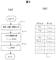
続いて、添付の図3により、ランプの点灯動作の各時点において、ランプの経時変化に関する情報、具体的には、予め測定された放電ランプのランプ電圧(LV)の変動に従って、付加すべきパルス状電流の値(Iad)を最適に設定するための処理について、以下に説明する。 Subsequently, according to the attached FIG. 3, at each time point of the lamp lighting operation, the pulse to be added according to the information about the change with time of the lamp, specifically, the fluctuation of the lamp voltage (LV) of the discharge lamp measured in advance. A process for optimally setting the value of the current (I ad ) will be described below.
すなわち、上記演算処理回路17は、図3(a)にも示す処理を実行するため、その記憶部に格納されたプログラムを、例えば、20時間〜200時間程度を単位とするタイミングで起動する。そして、その内部のタイマなどに基づいて積算された、装置の作動時間(即ち、高圧放電ランプ13の使用(点灯)時間)を得る(ステップS11)。続いて、図3(b)にも示すように、上記のステップで得た作動(点灯)時間(T1、T2…Tn、Tn+1…)をアドレス値として、上記記憶手段(メモリ)171に格納したデータである、上記パルス状電流の値(IadT1、IadT2、…IadTN、IadTN+1…)を入力する(ステップS12)。その後、その入力した電流値をドライブ回路23に指示し(ステップS13)、処理を終了する。
That is, since the
このことによれば、上述した従来技術のように、高圧放電ランプの動作パラメータとして、その電極間距離を示すパラメータである作動期間中のランプ電圧などを検出する必要はなく、単に、ランプの作動(点灯)時間に基づいて記憶手段(メモリ)171を参照するだけで、簡単に、放電ランプに付加的に供給されるべきパルス状電流の値(Iad)を、適宜、最適な値に設定することが可能となる。即ち、高圧放電ランプの長期に亘る使用における電極間距離等の動作パラメータの変化にも拘わらず、安定した光出力が得られると共に、放電に伴う電極の消耗によるアーク電圧の変化やフリッカ(チラツキ)の発生を低減することが可能となり、かつ、高圧放電ランプの寿命を短縮することもない。 According to this, it is not necessary to detect the lamp voltage during the operation period, which is a parameter indicating the distance between the electrodes, as the operation parameter of the high-pressure discharge lamp as in the above-described prior art. By simply referring to the storage means (memory) 171 based on the (lighting) time, the value (I ad ) of the pulsed current to be additionally supplied to the discharge lamp is simply set to an optimal value as appropriate. It becomes possible to do. That is, a stable light output can be obtained regardless of changes in the operating parameters such as the distance between the electrodes when the high-pressure discharge lamp is used over a long period of time, and arc voltage change and flicker (flicker) due to electrode wear due to discharge. It is possible to reduce the occurrence of the high pressure discharge lamp and not to shorten the life of the high pressure discharge lamp.
なお、以上に説明した例では、予め求めておいた前記放電ランプの作動電圧の経時変化に基づいて、付加すべきパルス状電流の大きさ(電流値)Iadを予め算出しておき、これを記憶手段(メモリ)171に格納しておくものとして説明した。しかしながら、本発明は、これのみに限定されることなく、例えば、予め求めておいた前記放電ランプの作動電圧の経時変化であるランプ電圧(LV)の値を記憶手段(メモリ)171に格納することも可能である。なお、その場合には、上記演算処理回路17は、読み出したランプ電圧(LV)の値に基づいて付加すべきパルス状電流の大きさ(電流値)Iadを設定することとなる。
In the example described above, the magnitude (current value) I ad of the pulsed current to be added is calculated in advance based on the change over time of the operating voltage of the discharge lamp that has been obtained in advance. Has been described as being stored in the storage means (memory) 171. However, the present invention is not limited to this. For example, the value of the lamp voltage (LV), which is a change with time of the operating voltage of the discharge lamp obtained in advance, is stored in the storage means (memory) 171. It is also possible. In this case, the
また、更には、上述したように、ランプ電圧(LV)は、その使用(点灯)時間の経過と共に、ほぼ一定の割合で上昇してゆく傾向を示していることから、以下の(式1)により、任意の時間t毎に、簡単に算出することも可能である。 Furthermore, as described above, the lamp voltage (LV) tends to increase at a substantially constant rate as the usage (lighting) time elapses. Thus, it is possible to easily calculate for every arbitrary time t.
LV=70+(100−70)20t/8000=70+3/40t…(式1) LV = 70 + (100−70) 20t / 8000 = 70 + 3 / 40t (Formula 1)
なお、ここでは、上記の図4に示した、8000時間の寿命を持つ定格100Wの高圧放電ランプにおける場合の例を示している。なお、このように、所定の演算式を用いて、使用(点灯)時間に対して変化するランプ電圧(LV)求める場合には、予めその算出のための式を用意しておく必要があるが、しかしながら、一方では、上述した記憶手段(メモリ)171を不要とすることから好適である。また、予め用意する演算式も、上述のように、一次式の簡単な演算であり、予め測定した放電ランプのランプ電圧(LV)の値(特に、200時間経過後の値と最大時間(寿命)での値)に基づいて、簡単に設定することが可能であり、容易に実現することが出来ることは明らかであろう。 Here, an example in the case of the high-pressure discharge lamp rated at 100 W and having a lifetime of 8000 hours shown in FIG. 4 is shown. As described above, when a lamp voltage (LV) that changes with use (lighting) time is obtained using a predetermined arithmetic expression, it is necessary to prepare an expression for the calculation in advance. However, on the other hand, it is preferable because the storage means (memory) 171 described above is unnecessary. In addition, the calculation formula prepared in advance is also a simple calculation of the primary formula as described above, and the value of the lamp voltage (LV) of the discharge lamp measured in advance (particularly, the value after 200 hours and the maximum time (lifetime). It is obvious that it can be easily set based on the value of) and can be easily realized.
更に、上記の例では、放電ランプの発光時に供給されるランプ電流の波形を、上記図2に示したように、正及び負の極性に連続的に交互に変化する矩形状のランプ電流(I0)の後端部にパルス状の電流を付加(I0+Iad)した波形として説明したが、しかしながら、本発明はこれに限定されることはなく、これに代えて、例えば、添付の図8に示すような波形とすることも可能である。 Furthermore, in the above example, as shown in FIG. 2, the waveform of the lamp current supplied when the discharge lamp emits light is a rectangular lamp current (I 0 ) was explained as a waveform in which a pulse-like current was added (I 0 + I ad ) to the rear end portion, however, the present invention is not limited to this, and instead of this, for example, the attached figure A waveform as shown in FIG.
即ち、図8(a)に示すランプ電流波形は、正及び負の極性に連続的に交互に変化すると共に、電流値を(I0)から(I0+Iad)に連続的に変化させたものである。また、図8(a)に示すランプ電流波形は、正及び負の極性に連続的に交互に変化する矩形に続いて、しかしながらこれとは独立して、パルス状の電流を付加したものである。なお、この独立して付加したパルス状の電流値は、(I0+Iad)となっている。なお、この場合においても、このIadの値を、放電ランプの作動電圧の経時変化に基づいて、上記の実施例と同様にして、最適に設定することが出来ることは説明するまでもない。 That is, the lamp current waveform shown in FIG. 8 (a), along with changes in the positive and negative polarity continuously alternating, a continuously changing the current value from (I 0) to (I 0 + I ad) Is. In addition, the lamp current waveform shown in FIG. 8A is obtained by adding a pulsed current independently of a rectangle that alternately and alternately changes to positive and negative polarities. . The pulse-like current value added independently is (I 0 + I ad ). Also in this case, the value of this I ad, based on the temporal change of the operating voltage of the discharge lamp, as in the above embodiment, needless to best explains that can be set.
また、これらのランプ電流波形によっても、やはり上記と同様に、高圧放電ランプの動作パラメータとして、その電極間距離を示すパラメータである作動期間中のランプ電圧などを検出する必要はなく、かつ、高圧放電ランプの長期に亘る使用における電極間距離等の動作パラメータの変化にも拘わらず、安定した光出力が得られると共に、放電に伴う電極の消耗によるアーク電圧の変化やフリッカ(チラツキ)の発生を低減することが可能となる。更には、高圧放電ランプの寿命を短縮することもないという効果が得られることは明らかであろう。 Also, with these lamp current waveforms, as described above, it is not necessary to detect the lamp voltage during the operation period, which is a parameter indicating the distance between the electrodes, as the operating parameter of the high-pressure discharge lamp. Regardless of changes in operating parameters such as the distance between electrodes during long-term use of a discharge lamp, stable light output can be obtained, and arc voltage change and flickering caused by electrode wear due to discharge can be prevented. It becomes possible to reduce. Further, it will be apparent that the effect of not shortening the life of the high-pressure discharge lamp can be obtained.
1…電源 8,9,10,11…MOS−FET 23…ドライブ回路2 27…イグナイタ回路 17…演算処理回路 171…メモリ 13…放電ランプ。
DESCRIPTION OF
Claims (8)
電源と、
前記電源の電力を正及び負の極性に連続的に交互に変化する交流電圧に変換して作動電圧を生成する手段と、
前記手段による作動電圧の生成を制御するための制御手段とを備え、もって、前記生成された作動電圧を前記放電ランプの一対の電極に印加して発光させるものにおいて、
前記制御手段は、前記放電ランプの発光時に供給されるランプ電流の特定の部位にパルスを供給すると共に、当該パルスの大きさを、予め測定された前記放電ランプの点灯時間に対する前記放電ランプの作動電圧の変動に従って設定する手段を備えていることを特徴とするランプ作動制御装置。 A lamp operation control device for operating a discharge lamp having a pair of electrodes disposed at both ends of an arc tube with a specific length interval,
Power supply,
Means for converting the power of the power source into an alternating voltage that continuously and alternately changes to positive and negative polarities to generate an operating voltage;
Control means for controlling generation of the operating voltage by the means, and applying the generated operating voltage to a pair of electrodes of the discharge lamp to emit light,
The control means supplies a pulse to a specific part of the lamp current supplied at the time of light emission of the discharge lamp, and determines the magnitude of the pulse for the operation of the discharge lamp with respect to the lighting time of the discharge lamp measured in advance. A lamp operation control device comprising means for setting in accordance with voltage fluctuations.
前記電源の電力を正及び負の極性に連続的に交互に変化する交流電圧に変換して作動電圧を生成し、当該生成された作動電圧を前記放電ランプの一対の電極に印加して発光させるものにおいて、
前記放電ランプの発光時に供給されるランプ電流の特定の部位にパルスを供給すると共に、当該パルスの大きさを、予め測定された前記放電ランプの点灯時間に対する前記放電ランプの作動電圧の変動に従って、設定することを特徴とするランプ作動制御方法。 A lamp operation control method for operating a discharge lamp having a pair of electrodes disposed at both ends of an arc tube with a specific length interval,
The power of the power source is converted into an alternating voltage that alternately and alternately changes to positive and negative polarities to generate an operating voltage, and the generated operating voltage is applied to a pair of electrodes of the discharge lamp to emit light. In things,
While supplying a pulse to a specific part of the lamp current supplied at the time of light emission of the discharge lamp, the magnitude of the pulse according to the fluctuation of the operating voltage of the discharge lamp with respect to the lighting time of the discharge lamp measured in advance A lamp operation control method comprising: setting a lamp operation control method.
Priority Applications (3)
| Application Number | Priority Date | Filing Date | Title |
|---|---|---|---|
| JP2004206263A JP4448396B2 (en) | 2004-07-13 | 2004-07-13 | Lamp operation control device and method thereof |
| US11/178,449 US7274157B2 (en) | 2004-07-13 | 2005-07-12 | Lamp operation controller and controlling method of lamp operation |
| CN2005100831665A CN1735308B (en) | 2004-07-13 | 2005-07-13 | Lamp operation controller and controlling method of lamp operation |
Applications Claiming Priority (1)
| Application Number | Priority Date | Filing Date | Title |
|---|---|---|---|
| JP2004206263A JP4448396B2 (en) | 2004-07-13 | 2004-07-13 | Lamp operation control device and method thereof |
Related Child Applications (1)
| Application Number | Title | Priority Date | Filing Date |
|---|---|---|---|
| JP2009251871A Division JP5222825B2 (en) | 2009-11-02 | 2009-11-02 | Lamp operation control device and method thereof |
Publications (2)
| Publication Number | Publication Date |
|---|---|
| JP2006032017A true JP2006032017A (en) | 2006-02-02 |
| JP4448396B2 JP4448396B2 (en) | 2010-04-07 |
Family
ID=35598771
Family Applications (1)
| Application Number | Title | Priority Date | Filing Date |
|---|---|---|---|
| JP2004206263A Active JP4448396B2 (en) | 2004-07-13 | 2004-07-13 | Lamp operation control device and method thereof |
Country Status (3)
| Country | Link |
|---|---|
| US (1) | US7274157B2 (en) |
| JP (1) | JP4448396B2 (en) |
| CN (1) | CN1735308B (en) |
Cited By (18)
| Publication number | Priority date | Publication date | Assignee | Title |
|---|---|---|---|---|
| JP2008192388A (en) * | 2007-02-02 | 2008-08-21 | Iwasaki Electric Co Ltd | High pressure discharge lamp lighting device, projector, and lighting method of high pressure discharge lamp |
| JP2008226650A (en) * | 2007-03-13 | 2008-09-25 | Osram-Melco Ltd | High pressure discharge lamp device |
| JP2009026746A (en) * | 2007-06-18 | 2009-02-05 | Seiko Epson Corp | Projector |
| JP2009117338A (en) * | 2007-10-16 | 2009-05-28 | Seiko Epson Corp | Light source device, projector, and driving method of light source device |
| JP2009158238A (en) * | 2007-12-26 | 2009-07-16 | Panasonic Corp | High pressure discharge lamp lighting device, high pressure discharge lamp device using the same, projector using the high pressure discharge lamp device, and lighting method of high pressure discharge lamp |
| JP2009199865A (en) * | 2008-02-21 | 2009-09-03 | Seiko Epson Corp | Driving system and driving device of discharge lamp, light source device, and image display device |
| JP2009199739A (en) * | 2008-02-19 | 2009-09-03 | Seiko Epson Corp | Method of driving discharge lamp, driving device, and projector |
| JP2009205889A (en) * | 2008-02-27 | 2009-09-10 | Seiko Epson Corp | Driving method of discharge lamp, driving device, and projector |
| JP2009224193A (en) * | 2008-03-17 | 2009-10-01 | Seiko Epson Corp | Discharge lamp lighting device, its control method, and projector |
| JP2010040442A (en) * | 2008-08-07 | 2010-02-18 | Seiko Epson Corp | Driving device for discharge lamp, driving method, light source device, and image display |
| JP2010062122A (en) * | 2007-12-14 | 2010-03-18 | Seiko Epson Corp | Light source device, projector, and method of driving discharge lamp |
| JP2010062121A (en) * | 2007-12-18 | 2010-03-18 | Seiko Epson Corp | Light source device, projector, and method of driving discharge lamp |
| JP2010135343A (en) * | 2010-03-15 | 2010-06-17 | Seiko Epson Corp | Driving method and driving device of discharge lamp, light source device, and image display device |
| JP2010165607A (en) * | 2009-01-19 | 2010-07-29 | Iwasaki Electric Co Ltd | High pressure discharge lamp lighting device |
| JP2010287373A (en) * | 2009-06-10 | 2010-12-24 | Iwasaki Electric Co Ltd | High-pressure discharge lamp lighting device, and lighting method of high-pressure discharge lamp |
| US8167438B2 (en) | 2007-12-14 | 2012-05-01 | Seiko Epson Corporation | Light source device, projector, and driving method of discharge lamp |
| US8344645B2 (en) | 2008-02-29 | 2013-01-01 | Seiko Epson Corporation | Method of driving discharge lamp, driving device, and projector |
| JP2013533600A (en) * | 2010-08-11 | 2013-08-22 | オスラム ゲーエムベーハー | Driving a high-pressure discharge lamp outside the rated power range |
Families Citing this family (10)
| Publication number | Priority date | Publication date | Assignee | Title |
|---|---|---|---|---|
| JP5249342B2 (en) * | 2007-11-13 | 2013-07-31 | オスラム ゲーエムベーハー | Circuit apparatus and method for operating a high pressure discharge lamp |
| JP4525772B2 (en) * | 2008-02-25 | 2010-08-18 | セイコーエプソン株式会社 | projector |
| JP2010198785A (en) * | 2009-02-23 | 2010-09-09 | Panasonic Electric Works Co Ltd | High pressure discharge lamp lighting device, lighting apparatus, and lighting system |
| CN101925218B (en) * | 2009-06-09 | 2013-06-26 | 海洋王照明科技股份有限公司 | Flash control method of alarm lights |
| CN102860136A (en) * | 2010-04-21 | 2013-01-02 | 皇家飞利浦电子股份有限公司 | Pulsed operation of a discharge lamp |
| DE102010028838A1 (en) * | 2010-05-11 | 2011-11-17 | Osram Gesellschaft mit beschränkter Haftung | Method and device for operating a discharge lamp |
| JP6149351B2 (en) * | 2011-08-22 | 2017-06-21 | セイコーエプソン株式会社 | Light source apparatus, discharge lamp driving method, and projector |
| CA2903668C (en) * | 2013-03-21 | 2016-10-18 | Honda Motor Co., Ltd. | Power supply device |
| DE102013223138A1 (en) * | 2013-11-13 | 2015-05-13 | Osram Gmbh | Method for operating a discharge lamp and projection arrangement |
| JP2016162615A (en) * | 2015-03-03 | 2016-09-05 | セイコーエプソン株式会社 | Discharge lamp drive device, light source device, projector, and discharge lamp drive method |
Family Cites Families (11)
| Publication number | Priority date | Publication date | Assignee | Title |
|---|---|---|---|---|
| JPH038299A (en) * | 1989-06-02 | 1991-01-16 | Koito Mfg Co Ltd | Lighting circuit for high-pressure discharge lamp for vehicle |
| JP3447776B2 (en) * | 1993-09-17 | 2003-09-16 | 池田デンソー株式会社 | Discharge lamp lighting device |
| TW339496B (en) * | 1994-06-22 | 1998-09-01 | Philips Electronics Nv | Method and circuit arrangement for operating a high-pressure discharge lamp |
| DE4437453A1 (en) * | 1994-10-19 | 1996-04-25 | Patent Treuhand Ges Fuer Elektrische Gluehlampen Mbh | Method for operating a discharge lamp and circuit arrangement for operating a discharge lamp |
| TW490998B (en) | 1998-12-17 | 2002-06-11 | Koninkl Philips Electronics Nv | Circuit arrangement |
| US6215252B1 (en) * | 1998-12-29 | 2001-04-10 | Philips Electronics North America Corporation | Method and apparatus for lamp control |
| DE10021537A1 (en) * | 2000-05-03 | 2001-11-08 | Philips Corp Intellectual Pty | Method and device for operating a gas discharge lamp |
| WO2002093984A1 (en) * | 2001-05-16 | 2002-11-21 | Matsushita Electric Industrial Co., Ltd. | Discharge lamp lighting device and system comprising it |
| JP3736438B2 (en) * | 2001-11-26 | 2006-01-18 | ウシオ電機株式会社 | Light source device and power supply device |
| WO2003060619A1 (en) * | 2001-12-21 | 2003-07-24 | Koninklijke Philips Electronics N.V. | Electronic ballast with ignition and operation control |
| JP2004207018A (en) * | 2002-12-25 | 2004-07-22 | Seiko Epson Corp | Light source drive circuit, projector, lighting control method of light source, and computer-readable program for executing it |
-
2004
- 2004-07-13 JP JP2004206263A patent/JP4448396B2/en active Active
-
2005
- 2005-07-12 US US11/178,449 patent/US7274157B2/en active Active
- 2005-07-13 CN CN2005100831665A patent/CN1735308B/en active Active
Cited By (33)
| Publication number | Priority date | Publication date | Assignee | Title |
|---|---|---|---|---|
| JP2008192388A (en) * | 2007-02-02 | 2008-08-21 | Iwasaki Electric Co Ltd | High pressure discharge lamp lighting device, projector, and lighting method of high pressure discharge lamp |
| JP2008226650A (en) * | 2007-03-13 | 2008-09-25 | Osram-Melco Ltd | High pressure discharge lamp device |
| JP2009026746A (en) * | 2007-06-18 | 2009-02-05 | Seiko Epson Corp | Projector |
| JP4548519B2 (en) * | 2007-10-16 | 2010-09-22 | セイコーエプソン株式会社 | Light source device |
| JP2009117338A (en) * | 2007-10-16 | 2009-05-28 | Seiko Epson Corp | Light source device, projector, and driving method of light source device |
| US8269426B2 (en) | 2007-10-16 | 2012-09-18 | Seiko Epson Corporation | Light source apparatus, projector, and light source apparatus drive method |
| US8018178B2 (en) | 2007-10-16 | 2011-09-13 | Seiko Epson Corporation | Light source apparatus, projector, and light source apparatus drive method |
| US8203280B2 (en) | 2007-12-14 | 2012-06-19 | Seiko Epson Corporation | Light source device, projector, and driving method of discharge lamp |
| JP2012059718A (en) * | 2007-12-14 | 2012-03-22 | Seiko Epson Corp | Light source device, projector and method of driving discharge lamp |
| US8937436B2 (en) | 2007-12-14 | 2015-01-20 | Seiko Epson Corporation | Light source device, projector, and driving method of discharge lamp |
| JP2010062122A (en) * | 2007-12-14 | 2010-03-18 | Seiko Epson Corp | Light source device, projector, and method of driving discharge lamp |
| US8558471B2 (en) | 2007-12-14 | 2013-10-15 | Seiko Epson Corporation | Light source device, projector, and driving method of discharge lamp |
| US8167438B2 (en) | 2007-12-14 | 2012-05-01 | Seiko Epson Corporation | Light source device, projector, and driving method of discharge lamp |
| JP2010062121A (en) * | 2007-12-18 | 2010-03-18 | Seiko Epson Corp | Light source device, projector, and method of driving discharge lamp |
| JP2012234828A (en) * | 2007-12-18 | 2012-11-29 | Seiko Epson Corp | Light source device, projector, and discharge lamp driving method |
| JP2009158238A (en) * | 2007-12-26 | 2009-07-16 | Panasonic Corp | High pressure discharge lamp lighting device, high pressure discharge lamp device using the same, projector using the high pressure discharge lamp device, and lighting method of high pressure discharge lamp |
| JP2009199739A (en) * | 2008-02-19 | 2009-09-03 | Seiko Epson Corp | Method of driving discharge lamp, driving device, and projector |
| US8350489B2 (en) | 2008-02-19 | 2013-01-08 | Seiko Epson Corporation | Method of driving discharge lamp, driving device, and projector |
| JP4572940B2 (en) * | 2008-02-19 | 2010-11-04 | セイコーエプソン株式会社 | Discharge lamp driving method, driving device, and projector |
| US8044602B2 (en) | 2008-02-19 | 2011-10-25 | Seiko Epson Corporation | Method of driving discharge lamp, driving device, and projector |
| JP4530062B2 (en) * | 2008-02-21 | 2010-08-25 | セイコーエプソン株式会社 | Discharge lamp driving method and driving device, light source device, and image display device |
| JP2009199865A (en) * | 2008-02-21 | 2009-09-03 | Seiko Epson Corp | Driving system and driving device of discharge lamp, light source device, and image display device |
| JP4525774B2 (en) * | 2008-02-27 | 2010-08-18 | セイコーエプソン株式会社 | Discharge lamp driving method, driving device, and projector |
| JP2009205889A (en) * | 2008-02-27 | 2009-09-10 | Seiko Epson Corp | Driving method of discharge lamp, driving device, and projector |
| US8264164B2 (en) | 2008-02-27 | 2012-09-11 | Seiko Epson Corporation | Method of driving discharge lamp, driving device, and projector |
| US8344645B2 (en) | 2008-02-29 | 2013-01-01 | Seiko Epson Corporation | Method of driving discharge lamp, driving device, and projector |
| JP4678414B2 (en) * | 2008-03-17 | 2011-04-27 | セイコーエプソン株式会社 | Discharge lamp lighting device, control method therefor, and projector |
| JP2009224193A (en) * | 2008-03-17 | 2009-10-01 | Seiko Epson Corp | Discharge lamp lighting device, its control method, and projector |
| JP2010040442A (en) * | 2008-08-07 | 2010-02-18 | Seiko Epson Corp | Driving device for discharge lamp, driving method, light source device, and image display |
| JP2010165607A (en) * | 2009-01-19 | 2010-07-29 | Iwasaki Electric Co Ltd | High pressure discharge lamp lighting device |
| JP2010287373A (en) * | 2009-06-10 | 2010-12-24 | Iwasaki Electric Co Ltd | High-pressure discharge lamp lighting device, and lighting method of high-pressure discharge lamp |
| JP2010135343A (en) * | 2010-03-15 | 2010-06-17 | Seiko Epson Corp | Driving method and driving device of discharge lamp, light source device, and image display device |
| JP2013533600A (en) * | 2010-08-11 | 2013-08-22 | オスラム ゲーエムベーハー | Driving a high-pressure discharge lamp outside the rated power range |
Also Published As
| Publication number | Publication date |
|---|---|
| CN1735308B (en) | 2011-03-30 |
| US20060012316A1 (en) | 2006-01-19 |
| JP4448396B2 (en) | 2010-04-07 |
| US7274157B2 (en) | 2007-09-25 |
| CN1735308A (en) | 2006-02-15 |
Similar Documents
| Publication | Publication Date | Title |
|---|---|---|
| JP4448396B2 (en) | Lamp operation control device and method thereof | |
| JP5013108B2 (en) | Discharge lamp lighting device, control method therefor, and projector | |
| JP4434150B2 (en) | Discharge lamp lighting device and projector | |
| JP3794415B2 (en) | Discharge lamp lighting device and projector | |
| JP4876677B2 (en) | High pressure discharge lamp lighting device | |
| US7667413B2 (en) | High pressure discharge lamp operation method, operation device, light source device, and projection type image display device | |
| JP2006331951A (en) | High pressure discharge lamp and image projecting device | |
| JP4971782B2 (en) | Discharge lamp lighting device and image display device | |
| JP5087931B2 (en) | High pressure discharge lamp lighting device, projector and lighting method of high pressure discharge lamp | |
| JP2008181814A (en) | Lighting device of high pressure discharge lamp | |
| JP4182081B2 (en) | Discharge lamp driving device | |
| JP2011187368A (en) | Light source apparatus | |
| JP2012238520A (en) | Feed device for high pressure discharge lamp | |
| JP4175349B2 (en) | Discharge lamp lighting device and projector | |
| JP5222825B2 (en) | Lamp operation control device and method thereof | |
| JP2012014995A (en) | Lighting device of high voltage discharge lamp, lighting method of high voltage discharge lamp and projector | |
| JP5537118B2 (en) | High pressure discharge lamp lighting device and image display device using the same | |
| WO2015093117A1 (en) | Discharge lamp lighting apparatus | |
| JP2007103135A (en) | Lighting device | |
| JPH11305195A (en) | Method for indicating replacement time of back light lamp | |
| JP6673081B2 (en) | Discharge lamp lighting device and image forming apparatus provided with the same | |
| JP2016162615A (en) | Discharge lamp drive device, light source device, projector, and discharge lamp drive method | |
| JP2010205601A (en) | Image display device, and driving method of discharge lamp | |
| JP2003297590A (en) | Discharge lamp lighting device, light source device, and projection type display device | |
| JP2016173449A (en) | Projector and method for controlling projector |
Legal Events
| Date | Code | Title | Description |
|---|---|---|---|
| A621 | Written request for application examination |
Free format text: JAPANESE INTERMEDIATE CODE: A621 Effective date: 20060725 |
|
| RD02 | Notification of acceptance of power of attorney |
Free format text: JAPANESE INTERMEDIATE CODE: A7422 Effective date: 20060725 |
|
| A977 | Report on retrieval |
Free format text: JAPANESE INTERMEDIATE CODE: A971007 Effective date: 20090327 |
|
| A131 | Notification of reasons for refusal |
Free format text: JAPANESE INTERMEDIATE CODE: A131 Effective date: 20090512 |
|
| A521 | Request for written amendment filed |
Free format text: JAPANESE INTERMEDIATE CODE: A523 Effective date: 20090709 |
|
| A02 | Decision of refusal |
Free format text: JAPANESE INTERMEDIATE CODE: A02 Effective date: 20090804 |
|
| A521 | Request for written amendment filed |
Free format text: JAPANESE INTERMEDIATE CODE: A523 Effective date: 20091102 |
|
| A911 | Transfer to examiner for re-examination before appeal (zenchi) |
Free format text: JAPANESE INTERMEDIATE CODE: A911 Effective date: 20091111 |
|
| TRDD | Decision of grant or rejection written | ||
| A01 | Written decision to grant a patent or to grant a registration (utility model) |
Free format text: JAPANESE INTERMEDIATE CODE: A01 Effective date: 20100105 |
|
| A01 | Written decision to grant a patent or to grant a registration (utility model) |
Free format text: JAPANESE INTERMEDIATE CODE: A01 |
|
| A61 | First payment of annual fees (during grant procedure) |
Free format text: JAPANESE INTERMEDIATE CODE: A61 Effective date: 20100122 |
|
| FPAY | Renewal fee payment (event date is renewal date of database) |
Free format text: PAYMENT UNTIL: 20130129 Year of fee payment: 3 |
|
| R150 | Certificate of patent or registration of utility model |
Ref document number: 4448396 Country of ref document: JP Free format text: JAPANESE INTERMEDIATE CODE: R150 Free format text: JAPANESE INTERMEDIATE CODE: R150 |
|
| FPAY | Renewal fee payment (event date is renewal date of database) |
Free format text: PAYMENT UNTIL: 20140129 Year of fee payment: 4 |
|
| S111 | Request for change of ownership or part of ownership |
Free format text: JAPANESE INTERMEDIATE CODE: R313111 |
|
| R350 | Written notification of registration of transfer |
Free format text: JAPANESE INTERMEDIATE CODE: R350 |
|
| S111 | Request for change of ownership or part of ownership |
Free format text: JAPANESE INTERMEDIATE CODE: R313111 |
|
| R350 | Written notification of registration of transfer |
Free format text: JAPANESE INTERMEDIATE CODE: R350 |
|
| R250 | Receipt of annual fees |
Free format text: JAPANESE INTERMEDIATE CODE: R250 |
|
| R250 | Receipt of annual fees |
Free format text: JAPANESE INTERMEDIATE CODE: R250 |
|
| R250 | Receipt of annual fees |
Free format text: JAPANESE INTERMEDIATE CODE: R250 |
|
| S111 | Request for change of ownership or part of ownership |
Free format text: JAPANESE INTERMEDIATE CODE: R313111 |
|
| R350 | Written notification of registration of transfer |
Free format text: JAPANESE INTERMEDIATE CODE: R350 |
|
| R250 | Receipt of annual fees |
Free format text: JAPANESE INTERMEDIATE CODE: R250 |
|
| R250 | Receipt of annual fees |
Free format text: JAPANESE INTERMEDIATE CODE: R250 |
|
| R250 | Receipt of annual fees |
Free format text: JAPANESE INTERMEDIATE CODE: R250 |