JP2006018102A - Image display device - Google Patents
Image display device Download PDFInfo
- Publication number
- JP2006018102A JP2006018102A JP2004196999A JP2004196999A JP2006018102A JP 2006018102 A JP2006018102 A JP 2006018102A JP 2004196999 A JP2004196999 A JP 2004196999A JP 2004196999 A JP2004196999 A JP 2004196999A JP 2006018102 A JP2006018102 A JP 2006018102A
- Authority
- JP
- Japan
- Prior art keywords
- light
- projection
- liquid crystal
- crystal panel
- projection light
- Prior art date
- Legal status (The legal status is an assumption and is not a legal conclusion. Google has not performed a legal analysis and makes no representation as to the accuracy of the status listed.)
- Withdrawn
Links
Images


Landscapes
- Projection Apparatus (AREA)
- Liquid Crystal (AREA)
- Optical Modulation, Optical Deflection, Nonlinear Optics, Optical Demodulation, Optical Logic Elements (AREA)
Abstract
Description
本発明は、複数の空間変調素子を用いて画像を表示する画像表示装置に関する。 The present invention relates to an image display apparatus that displays an image using a plurality of spatial modulation elements.
近年の撮像装置の高解像度化に伴い、撮像画像を表示するための画像投影装置においても高解像度化の要望が高まっている。それに伴い、高画素数の表示素子(空間変調素子)の開発も進められているが、撮像素子の解像度に対して十分な解像度を有しているとは言えない状況である。 With the recent increase in resolution of imaging devices, there is an increasing demand for higher resolution in image projection devices for displaying captured images. Along with this, development of a display device (spatial modulation device) having a large number of pixels has been promoted, but it cannot be said that the display device has sufficient resolution with respect to the resolution of the imaging device.
従来、限られた画素数の空間変調素子(LCD等)を用いて高解像度を達成する技術として、偏光旋回液晶パネルと複屈折板を組み合わせて画素ずらしを行う技術(ウォブリング技術)が知られている。例えば、特許文献1及び特許文献2には、R、G及びBの空間変調素子からの投影光をダイクロイックプリズム(クロスプリズム)で合成し、合成されたR、G及びBの投影光を偏光旋回液晶パネルと複屈折板とからなる光線シフト部に供給する、という方法が提案されている。これらの提案では、R、G及びBの投影光の偏光方向を同一方向に揃えており、R、G及びBの投影光の光線を同時にシフトするようにしている。
Conventionally, as a technique for achieving high resolution using a spatial modulation element (LCD or the like) having a limited number of pixels, a technique for shifting pixels by combining a polarization rotating liquid crystal panel and a birefringent plate (a wobbling technique) is known. Yes. For example, in Patent Document 1 and
しかしながら、R、G及びBの投影光をクロスプリズムで合成して表示を行う場合、表示品質を高めるためには、G光の偏光方向とR光及びB光の偏光方向とを直交させることが重要であると言われている(例えば特許文献3参照)。上述した特許文献1及び特許文献2に記載された方法では、R、G及びBの投影光の偏光方向を同一方向に揃えているため、画像のコントラストの低下等が生じ、優れた表示品質を有する画像表示装置を得ることが困難である。また、R、G及びBの投影光の偏光方向が同一方向であるため、例えば前半のサブフレームではR、G及びBの光線をいずれもシフトせず、後半のサブフレームではR、G及びBの光線をいずれもシフトするというようにして表示を行う。したがって、前半のサブフレームではシフトしない画素位置でのみ表示が行われ、後半のサブフレームではシフトした画素位置でのみ表示が行われる。そのため、表示画像に粒状感等が生じ、優れた表示品質を有する画像表示装置を得ることが困難である。
このように、従来の画像表示装置では、R、G及びBの投影光の偏光方向を同一方向に揃えているため、優れた表示品質を有する画像表示装置を得ることが困難であった。 Thus, in the conventional image display apparatus, since the polarization directions of the R, G, and B projection lights are aligned in the same direction, it is difficult to obtain an image display apparatus having excellent display quality.
本発明は、上記従来の課題に対してなされたものであり、優れた表示品質を有する画像表示装置を提供することを目的としている。 The present invention has been made to solve the above-described conventional problems, and an object thereof is to provide an image display apparatus having excellent display quality.
本発明に係る画像表示装置は、入力された画像データに応じた画像を表示する画像表示装置であって、複数の色の画像を表示する複数の空間変調手段と、光源からの照明光を前記複数の空間変調手段で変調した複数の投影光を光学的に合成する光路合成手段と、前記空間変調手段の変調タイミングに同期して、前記光路合成手段で合成された各投影光の光線のシフト制御を投影光の偏光方向に基づいて行う光線シフト手段と、を備え、前記光線シフト手段は、投影光の色に応じて前記投影光の光線のシフト制御を行うことを特徴とする。 An image display device according to the present invention is an image display device that displays an image according to input image data, and a plurality of spatial modulation means for displaying an image of a plurality of colors, and illumination light from a light source. An optical path synthesis unit that optically synthesizes a plurality of projection lights modulated by a plurality of spatial modulation units, and a shift of the light beams of the projection lights synthesized by the optical path synthesis unit in synchronization with the modulation timing of the spatial modulation unit A light beam shift unit that performs control based on the polarization direction of the projection light, and the light beam shift unit performs shift control of the light beam of the projection light according to the color of the projection light.
前記画像表示装置において、前記光線シフト手段は、前記投影光の偏光方向を旋回することが可能な液晶パネルと、入射光が特定の方向に偏光されている場合に入射光の延長線上からずれた透過光を生じる複屈折板とを有し、前記液晶パネルは、前記空間変調手段の変調タイミングに同期して前記投影光の偏光方向を旋回することが好ましい。 In the image display device, the light beam shift means is displaced from a liquid crystal panel capable of rotating the polarization direction of the projection light and an extension line of the incident light when the incident light is polarized in a specific direction. Preferably, the liquid crystal panel rotates the polarization direction of the projection light in synchronization with the modulation timing of the spatial modulation means.
前記画像表示装置において、前記空間変調手段は、前記光源からの照明光を入力された画像データに応じて変調した投影光を生成する画像表示手段と、前記画像表示手段で生成された投影光を所定の1方向の偏光方向を有する投影光に変換する偏光変換手段とを有し、前記光路合成手段は、前記各偏光変換手段からの投影光の偏光方向の違いを用いて複数の投影光を光学的に合成することが好ましい。 In the image display device, the spatial modulation unit is configured to generate projection light generated by modulating illumination light from the light source according to input image data, and the projection light generated by the image display unit. Polarization conversion means for converting into projection light having a predetermined polarization direction, and the optical path synthesis means uses a difference in the polarization direction of the projection light from each polarization conversion means to output a plurality of projection lights. It is preferable to synthesize optically.
前記画像表示装置において、前記光路合成手段で合成された投影光は、P偏光及びS偏光の投影光であることが好ましい。 In the image display device, it is preferable that the projection light combined by the optical path combining unit is P-polarized light and S-polarized light.
前記画像表示装置において、前記空間変調手段で表示される複数の色は赤、緑及び青であり、赤の投影光と青の投影光の偏光方向は同じであり、緑の投影光の偏光方向は赤及び青の投影光の偏光方向と直交することが好ましい。 In the image display device, the plurality of colors displayed by the spatial modulation means are red, green and blue, and the polarization directions of the red projection light and the blue projection light are the same, and the polarization direction of the green projection light Is preferably orthogonal to the polarization directions of the red and blue projection light.
前記画像表示装置において、前記光線シフト手段により、前記緑の投影光はシフトし且つ赤及び青の投影光はシフトしない第1の状態と、前記緑の投影光はシフトせず且つ赤及び青の投影光はシフトする第2の状態とが切り換えられることが好ましい。 In the image display device, the light projection unit shifts the green projection light and does not shift the red and blue projection lights, and the green projection light does not shift and the red and blue projection light is shifted. The projection light is preferably switched between the second state where the projection light is shifted.
前記画像表示装置において、前記緑の投影光のシフト量と前記赤及び青の投影光のシフト量とは同じであることが好ましい。 In the image display device, it is preferable that the shift amount of the green projection light and the shift amount of the red and blue projection light are the same.
前記画像表示装置において、前記光路合成手段はクロスプリズムであり、前記緑の投影光が前記クロスプリズムに入射する際の光軸は、前記クロスプリズムで合成された投影光が前記クロスプリズムから前記光線シフト手段に出射する際の光軸と平行であり、前記赤及び青の投影光が前記クロスプリズムに入射する際の光軸は、前記クロスプリズムで合成された投影光が前記クロスプリズムから前記光線シフト手段に出射する際の光軸と略直交することが好ましい。 In the image display device, the optical path combining unit is a cross prism, and an optical axis when the green projection light is incident on the cross prism is such that the projection light combined by the cross prism is transmitted from the cross prism to the light beam. The optical axis when the red and blue projection lights are incident on the cross prism is parallel to the optical axis when emitted to the shift means, and the projection light synthesized by the cross prism is transmitted from the cross prism to the light beam. It is preferable to be substantially orthogonal to the optical axis when emitted to the shift means.
前記画像表示装置において、前記光路合成手段はPBSプリズムであり、前記緑の投影光が前記PBSプリズムに入射する際の光軸は、前記PBSプリズムで合成された投影光が前記PBSプリズムから前記光線シフト手段に出射する際の光軸と平行であり、前記赤及び青の投影光が前記PBSプリズムに入射する際の光軸は、前記クロスプリズムで合成された投影光が前記PBSプリズムから前記光線シフト手段に出射する際の光軸と略直交することが好ましい。 In the image display device, the optical path combining unit is a PBS prism, and an optical axis when the green projection light is incident on the PBS prism is that the projection light combined by the PBS prism is transmitted from the PBS prism to the light beam. The optical axis when the red and blue projection lights are incident on the PBS prism is parallel to the optical axis when emitted to the shift means, and the projection light synthesized by the cross prism is transmitted from the PBS prism to the light beam. It is preferable to be substantially orthogonal to the optical axis when emitted to the shift means.
前記画像表示装置において、前記空間変調手段で変調された緑の投影光はP偏光であり、前記空間変調手段で変調された赤及び青の投影光はS偏光であることが好ましい。 In the image display device, it is preferable that the green projection light modulated by the spatial modulation unit is P-polarized light, and the red and blue projection light modulated by the spatial modulation unit is S-polarized light.
前記画像表示装置において、前記光線シフト手段でシフト制御された各色の投影光を観察者に観察可能なように結像する光学手段をさらに備え、前記光学手段によって結像した各色の結像位置は、前記赤の投影光と青の投影光とが常に一致し、前記光線シフト手段でシフトされた緑の投影光と前記光線シフト手段でシフトされない赤及び青の投影光とが一致し、前記光線シフト手段でシフトされない緑の投影光と、前記光線シフト手段でシフトされた赤及び青の投影光とが一致することが好ましい。 In the image display device, the image display device further includes an optical unit configured to form an image so that an observer can observe the projection light of each color shift-controlled by the light beam shift unit, and an imaging position of each color imaged by the optical unit is The red projection light always matches the blue projection light, the green projection light shifted by the light beam shift means matches the red and blue projection lights not shifted by the light beam shift means, and the light rays It is preferable that the green projection light not shifted by the shift means and the red and blue projection lights shifted by the light beam shift means coincide.
本発明によれば、投影光の色に応じて投影光の光線のシフト制御を行うことにより、表示画像に粒状感等が生じるといった現象を防止することができ、優れた表示品質を有する画像表示装置を得ることが可能となる。 According to the present invention, by controlling the shift of the light of the projection light according to the color of the projection light, it is possible to prevent a phenomenon such as a graininess in the display image, and to display an image with excellent display quality. An apparatus can be obtained.
以下、本発明の実施形態を図面を参照して説明する。 Hereinafter, embodiments of the present invention will be described with reference to the drawings.
(実施形態1)
図1は、本発明の第1の実施形態に係り、3板式液晶プロジェクター(画像投影装置)の概略を示した図である。
(Embodiment 1)
FIG. 1 is a diagram showing an outline of a three-plate liquid crystal projector (image projection apparatus) according to the first embodiment of the present invention.
光源110には、超高圧水銀ランプやキセノンランプ等のアーク放電ランプが用いられる。光源110の出射側には、光源110の照明ムラを低減するためのフライアイレンズ120、光源110の偏光方向を一方向に揃えるためのPS変換素子130、光路長を揃えるためのリレーレンズ(図示せず)等が設けられている。
As the
光源110からの光はダイクロイックミラー141に入射し、ダイクロイックミラー141でR(赤)光が反射する。ダイクロイックミラー141で反射したR光は、ミラー142で反射し、後述する液晶表示パネル(LCDパネル)211に供給される。ダイクロイックミラー141を透過した光は、ダイクロイックミラー143に入射する。ダイクロイックミラー143ではG(緑)光が反射し、後述する液晶表示パネル(LCDパネル)221に供給される。ダイクロイックミラー143を透過した光は、ダイクロイックミラー144に入射する。ダイクロイックミラー144で反射したB(青)光は、ミラー145で反射し、後述する液晶表示パネル(LCDパネル)231に供給される。
Light from the
このようにして、照明光としてR光、G光及びB光が生成される。なお、上述した例では、光源110に白色光源を用い、ダイクロイックミラーでR光、G光及びB光を色分離するようにしているが、R光用のLED、G光用のLED及びB光用のLEDを用いるようにしてもよい。
In this way, R light, G light, and B light are generated as illumination light. In the above-described example, a white light source is used as the
上記のようにして色分離されたR光、G光及びB光はそれぞれ、透過型LCD(画像表示部)211及び偏光板(偏光変換部)212からなる空間変調部210、透過型LCD(画像表示部)221及び偏光板(偏光変換部)222からなる空間変調部220、及び透過型LCD(画像表示部)231及び偏光板(偏光変換部)232からなる空間変調部230に供給される。光源110からの照明光はPS変換素子130によって偏光方向が一方向に揃えられているため、ミラー141〜145と透過型LCD211、221及び231との幾何学的な位置関係を適切に設定することにより、透過型LCD211にはP偏光のR光が、透過型LCD221にはS偏光のG光が、透過型LCD231にはP偏光のB光が入射する。
The R light, G light, and B light color-separated as described above are respectively a
透過型LCD211、221及び231は、画像データ(映像信号)に応じて入射光(照明光)を空間変調するものであり、透過型LCD211ではR画像、透過型LCD221ではG画像、透過型LCD231ではB画像が生成される。透過型LCD211で生成されたR画像の画像光は偏光板212を通過することでS偏光に変換され、透過型LCD221で生成されたG画像の画像光は偏光板222を通過することでP偏光に変換され、透過型LCD231で生成されたB画像の画像光は偏光板232を通過することでS偏光に変換される。通常、透過型LCDの入射側と出射側には、入射光の偏光方向と出射光の偏光方向とが直交するように偏光板がそれぞれ配設されているが、図1では入射側の偏光板は図示していない。また、入射側の偏光板の偏光方向は、PS変換素子130で生成された光の偏光方向と同一の方向となるように構成されている。
The
このようにして、空間変調部210からはS偏光のR光が、空間変調部220からはP偏光のG光が、空間変調部230からはS偏光のB光が、それぞれクロスプリズム(ダイクロイックプリズム)310に供給される。
In this way, the S-polarized R light from the
空間変調部210からのR光は、クロスプリズム310の反射面311で反射し、クロスプリズム310の出射面から出射する。空間変調部220からのG光は、クロスプリズム310を直進し、クロスプリズム310の出射面から出射する。空間変調部230からのB光は、クロスプリズム310の反射面312で反射し、クロスプリズム310の出射面から出射する。すなわち、R光及びB光については入射光の光軸と出射光の光軸とが直交し、G光については入射光の光軸と出射光の光軸とが平行となる。
The R light from the
このようにして、空間変調部210、220及び230からクロスプリズム310に供給されたR光(S偏光)、G光(P偏光)及びB光(S偏光)は、クロスプリズム310によって一つの光路に光路合成される。
In this way, the R light (S-polarized light), G light (P-polarized light), and B light (S-polarized light) supplied from the
クロスプリズム310で光路合成された投影光(映像光)は、光線シフト部400に入射する。この光線シフト部400は、偏光を旋回可能な偏光旋回液晶パネル410と、複屈折性を有する複屈折板420とによって構成されている。
The projection light (image light) synthesized by the cross prism 310 is incident on the light beam shift unit 400. The light beam shifting unit 400 includes a polarization-rotating
液晶パネル410は、TN型液晶パネルを用いて構成されており、印加電圧のオン・オフによって偏光の旋回を制御できるように構成されている。すなわち、液晶パネル410への印加電圧がオフの場合には、P偏光は90度旋回してS偏光に、S偏光も同様に90度旋回してP偏光となる。すなわち、液晶パネル410への印加電圧がオフの場合には、G光についてはP偏光からS偏光に変換され、R光及びB光についてはS偏光からP偏光に変換される。液晶パネル410への印加電圧がオンの場合には、P偏光は旋回せずにP偏光のまま液晶パネル410を通過し、同様にS偏光も旋回せずにS偏光のまま液晶パネル410を通過する。すなわち、液晶パネル410への印加電圧がオンの場合には、R光、G光及びB光ともに旋回せずに液晶パネル410を通過する。なお、図1では、液晶パネル410がオフ状態の場合を示している。
The
複屈折板420は、複屈折性を有する無色透明の結晶板であり、水晶板やニオブ酸リチウム板等を用いることが可能である。通常は結晶軸が入射面に対して45度になるように構成されており、入射光の偏光方向に応じて入射光を常光(no)と異常光(ne)とに分離する性質を有している。本実施形態では、S偏光の光線は常光として複屈折板420でシフトせずに複屈折板420を通過し、P偏光の光線は異常光として複屈折板420でシフトするようになっている。シフト量は、複屈折板420の材質と厚さによって決めることができる。 The birefringent plate 420 is a colorless and transparent crystal plate having birefringence, and a quartz plate, a lithium niobate plate, or the like can be used. Usually, the crystal axis is 45 degrees with respect to the incident surface, and has the property of separating incident light into ordinary light (no) and extraordinary light (ne) according to the polarization direction of the incident light. ing. In this embodiment, the S-polarized light beam passes through the birefringent plate 420 without being shifted by the birefringent plate 420 as ordinary light, and the P-polarized light beam is shifted by the birefringent plate 420 as extraordinary light. The shift amount can be determined by the material and thickness of the birefringent plate 420.
光線シフト部400からの投影光は、投影光学系510を介してスクリーン520上に投影される。なお、スクリーン520には、偏光依存性のないものを用いることが好ましいが、偏光スクリーンのような偏光依存性のあるものを用いる場合には、光線シフト部400とスクリーン520との間に波長板を設けて、偏光方向の影響を低減するようにしてもよい。 Projection light from the light beam shift unit 400 is projected onto the screen 520 via the projection optical system 510. In addition, it is preferable to use a screen having no polarization dependency as the screen 520, but when a screen having a polarization dependency such as a polarizing screen is used, a wave plate is disposed between the light shift unit 400 and the screen 520. May be provided to reduce the influence of the polarization direction.
図2は、透過型LCD211、221及び231それぞれの画素配列を示した図である。図3は、光線シフト部400を通過した後の、透過型LCD211、221及び231からの投影光の投影面(スクリーン面)上での画素配列状態を示した図である。図3(A)は液晶パネル410の印加電圧がオフの場合、図3(B)は液晶パネル410の印加電圧がオンの場合を示している。なお、図2及び図3では、説明の都合上、各画素の開口率を小さくし各画素が重ならないようにして図示しているが、各画素の開口率は、例えば図3において隣接する画素が重なる程度に大きくてもよい。
FIG. 2 is a diagram showing a pixel arrangement of each of the
図4は光線シフト部400の作用を説明するための図であり、図4(A)は液晶パネル410の印加電圧がオフの場合、図4(B)は液晶パネル410の印加電圧がオンの場合を示している。なお、図4(A)及び図4(B)では、説明の都合上、クロスプリズム310から出射されたP偏光(G光)の光線及びS偏光(R光及びB光)の光線を垂直方向にずらして描いているが、実際にはP偏光の光線の光路とS偏光の光線の光路とは一致している。
4A and 4B are diagrams for explaining the operation of the light beam shifting unit 400. FIG. 4A shows the case where the applied voltage of the
図4(A)に示すように、偏光旋回液晶パネル410がオフの場合には、クロスプリズム310からのP偏光(G光)は液晶パネル410でS偏光に旋回され、液晶パネル410からのS偏光はシフトすることなく複屈折板420を通過する。クロスプリズム310からのS偏光(R光及びB光)は液晶パネル410でP偏光に旋回され、液晶パネル410からのP偏光は複屈折板420で1/2画素ピッチ分シフトされる。したがって、偏光旋回液晶パネル410がオフの場合には、図3(A)に示すように、G光の画素位置(a)に対してR光及びB光の画素位置(b)は、投影面(スクリーン面)上において1/2画素ピッチ分ずれた状態となる。
As shown in FIG. 4A, when the polarization rotation
図4(B)に示すように、液晶パネル410がオンの場合には、クロスプリズム310からのP偏光(G光)は、液晶パネル410で旋回されることなく液晶パネル410を通過し、複屈折板420で1/2画素ピッチ分シフトされる。クロスプリズム310からのS偏光(R光及びB光)は、液晶パネル410で旋回されることなく液晶パネル410を通過し、複屈折板420でシフトすることなく複屈折板420を通過する。したがって、液晶パネル410がオンの場合には、図3(B)に示すように、R光及びB光の画素位置(a)に対してG光の画素位置(b)は、投影面(スクリーン面)上において1/2画素ピッチ分ずれた状態となる。
As shown in FIG. 4B, when the
以上の説明からわかるように、偏光旋回液晶パネル410のオン・オフを切り換えることにより、光線シフト部400への入射光の偏光方向に応じて、入射光をシフトするか否かの制御を行うことができる。したがって、透過型LCD211、221及び231の変調タイミングに同期して、偏光旋回液晶パネル410のオン・オフを時間的に切り換えることで、図3(A)に示した表示状態と図3(B)に示した表示状態とを時間軸方向で合成することができる。その結果、投影光学系510を介してスクリーン520上に画像を投影することで、透過型LCD211、221及び231個々の画素数の2倍の画素数で表示を行うことが可能となる。
As can be understood from the above description, whether or not the incident light is shifted is controlled according to the polarization direction of the incident light to the light beam shifting unit 400 by switching the polarization rotation
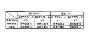
図5は、上述した原理に基づいて表示を行う場合の動作を示した図である。図に示すように、1フレームを第1サブフレーム(1フレームの前半)と第2サブフレーム(1フレームの後半)に分割し、第1サブフレームでは偏光旋回液晶パネル410をオン状態に、第2サブフレームでは偏光旋回液晶パネル410をオフ状態にする。その結果、第1サブフレームでは、画素位置aにR画像及びB画像が表示され、画素位置bにG画像が表示される。第2サブフレームでは逆に、画素位置aにG画像が表示され、画素位置bにR画像及びB画像が表示される。したがって、1フレーム全体で見れば、画素位置a及び画素位置bともに、R、G及びBのフルカラー画像が表示されることになる。
FIG. 5 is a diagram showing an operation when displaying based on the above-described principle. As shown in the figure, one frame is divided into a first sub-frame (the first half of one frame) and a second sub-frame (the second half of one frame). In the first sub-frame, the polarization rotation
図6は、上述した画像表示装置において、上述したような表示(2点画素ずらしの表示)を実現するための構成を示したブロック図である。 FIG. 6 is a block diagram illustrating a configuration for realizing the above-described display (display by shifting two pixels) in the above-described image display apparatus.
入力映像信号の画像データは、フレームメモリー601に記憶される。画像情報生成回路602では、フレームメモリー601に記憶された映像信号から、画素位置a及びbに対応する信号成分を抽出(サンプリング)する。
The image data of the input video signal is stored in the
タイミング信号発生器603からのタイミング信号により、第1サブフレームでは、画素位置aにおけるR及びBの画像データ並びに画素位置bにおけるGの画像データが駆動回路604に供給される。駆動回路604からは透過型LCD211、221及び231に駆動信号が送られ、透過型LCD211、221及び231が駆動される。駆動回路605では、タイミング信号発生器603からのタイミング信号に基づき、透過型LCD211、221及び231の駆動タイミング(表示タイミング)に同期して、偏光旋回液晶パネル410をオン状態にする。その結果、第1サブフレームでは図3(B)に示したような表示状態が得られる。
By the timing signal from the
タイミング信号発生器603からのタイミング信号により、第2サブフレームでは、画素位置aにおけるGの画像データ並びに画素位置bにおけるR及びBの画像データが駆動回路604に供給される。駆動回路604からは透過型LCD211、221及び231に駆動信号が送られ、透過型LCD211、221及び231が駆動される。駆動回路605では、タイミング信号発生器603からのタイミング信号に基づき、透過型LCD211、221及び231の駆動タイミング(表示タイミング)に同期して、偏光旋回液晶パネル410をオフ状態にする。その結果、第2サブフレームでは図3(A)に示したような表示状態が得られる。
By the timing signal from the
このようにして、図3(A)に示したような表示状態と図3(B)に示したような表示状態が時間軸方向で合成され、スクリーン520上には1つの空間変調素子の画素数の2倍の画素数の画像が表示される。 In this way, the display state as shown in FIG. 3A and the display state as shown in FIG. 3B are synthesized in the time axis direction, and a pixel of one spatial modulation element is displayed on the screen 520. An image having twice the number of pixels is displayed.
以上のように、本実施形態によれば、第1サブフレームでは、画素位置aにR画像及びB画像が表示され、画素位置bにG画像が表示される。第2サブフレームでは逆に、画素位置aにG画像が表示され、画素位置bにR画像及びB画像が表示される。したがって、第1サブフレーム及び第2サブフレームともに画素位置a及び画素位置bのいずれにも表示が行われることになる。そのため、表示画像に粒状感等が生じるといった現象を防止することができ、優れた表示品質を有する画像表示装置を得ることができる。 As described above, according to the present embodiment, in the first subframe, the R image and the B image are displayed at the pixel position a, and the G image is displayed at the pixel position b. Conversely, in the second subframe, the G image is displayed at the pixel position a, and the R image and the B image are displayed at the pixel position b. Therefore, display is performed at both the pixel position a and the pixel position b in both the first subframe and the second subframe. Therefore, it is possible to prevent a phenomenon that graininess or the like occurs in the display image, and an image display device having excellent display quality can be obtained.
また、従来のように、R、G及びBの投影光の偏光方向を一方向に揃えるのではなく、G画像の投影光の偏光方向とR及びB画像の投影光の偏光方向とが直交するようにしている。従来技術でも述べたように、R、G及びBの投影光をクロスプリズムで合成する場合、表示品質を高めるためにはG光の偏光方向とR光及びB光の偏光方向とを直交させることが重要である。本実施形態によれば、第1サブフレーム及び第2サブフレームともにそのような直交関係が得られるため、画像のコントラストや光量の低下等を防止することができ、優れた表示品質を有する画像表示装置を得ることができる。 In addition, the polarization directions of the R, G, and B projection lights are not aligned in a single direction as in the prior art, but the polarization directions of the G image and the R and B images are orthogonal to each other. I am doing so. As described in the prior art, when combining R, G, and B projection light with a cross prism, in order to improve display quality, the polarization direction of the G light and the polarization direction of the R light and B light should be orthogonal to each other. is important. According to the present embodiment, since such an orthogonal relationship is obtained in both the first subframe and the second subframe, it is possible to prevent a decrease in image contrast, light amount, and the like, and an image display having excellent display quality. A device can be obtained.
(実施形態2)
次に、本発明の第2の実施形態について説明する。第1の実施形態では、偏光旋回液晶パネル410と複屈折板420とからなる光線シフト部400によって2点画素ずらしを行うようにしたが、本実施形態では、偏光旋回液晶パネル及び複屈折板の数を増やすことで、4点画素ずらしを実現している。なお、3板式液晶プロジェクター(画像投影装置)全体の基本的な構成については第1の実施形態と同様であり、それらの詳細な説明は省略する。
(Embodiment 2)
Next, a second embodiment of the present invention will be described. In the first embodiment, the two-point pixel shift is performed by the light beam shift unit 400 including the polarization rotation
図7は、本実施形態における光路合成部及び光線シフト部の構成を模式的に示した斜視図である。 FIG. 7 is a perspective view schematically showing the configuration of the optical path synthesis unit and the light beam shift unit in the present embodiment.
クロスプリズム310の基本的な構成は図1に示したクロスプリズム310と同様であり、クロスプリズム310の出射面からはP偏光のG光とS偏光のR光及びB光が光線シフト部400に供給される。光線シフト部400は、偏光旋回液晶パネル(第1の液晶パネル)411、複屈折板(第1の複屈折板)421、偏光旋回液晶パネル(第2の液晶パネル)412及び複屈折板(第2の複屈折板)422によって構成されている。偏光旋回液晶パネル411及び412の機能は、第1の実施形態で示した偏光旋回液晶パネル410と同様であり、オフ状態のときには入射光の偏光方向が90度旋回し、オン状態のときには入射光の偏光方向は変化しない。複屈折板421は、入射光の光線を1/2画素ピッチ分水平方向にシフトするためのものであり、複屈折板422は、入射光の光線を1/2画素ピッチ分垂直方向にシフトするためのものである。なお、複屈折板421と複屈折板422の位置を入れ替えるようにしてもよい。
The basic configuration of the cross prism 310 is the same as that of the cross prism 310 shown in FIG. 1, and P-polarized G light, S-polarized R light, and B light enter the light beam shift unit 400 from the exit surface of the cross prism 310. Supplied. The beam shift unit 400 includes a polarization rotation liquid crystal panel (first liquid crystal panel) 411, a birefringence plate (first birefringence plate) 421, a polarization rotation liquid crystal panel (second liquid crystal panel) 412 and a birefringence plate (first liquid crystal panel). 2 birefringent plates) 422. The functions of the polarization rotation liquid crystal panels 411 and 412 are the same as those of the polarization rotation
上述したような構成により、図8に示すように、画素位置a、画素位置b、画素位置c及び画素位置dに画像を表示することができ、4点画素ずらしの画像表示を実現することが可能である。 With the configuration described above, as shown in FIG. 8, images can be displayed at the pixel position a, the pixel position b, the pixel position c, and the pixel position d, and an image display with four-point pixel shift can be realized. Is possible.
図9は、偏光旋回液晶パネル(第1の液晶パネル)411及び偏光旋回液晶パネル(第2の液晶パネル)412のオン・オフに応じた表示状態を示した図である。 FIG. 9 is a diagram illustrating a display state according to ON / OFF of the polarization rotation liquid crystal panel (first liquid crystal panel) 411 and the polarization rotation liquid crystal panel (second liquid crystal panel) 412.
図9(A)は、偏光旋回液晶パネル411がオフ状態で且つ偏光旋回液晶パネル412がオフ状態である場合の表示状態を示している。この場合には、画素位置aにG画像が表示され、画素位置dにR画像及びB画像が表示される。 FIG. 9A shows a display state when the polarization rotation liquid crystal panel 411 is in an off state and the polarization rotation liquid crystal panel 412 is in an off state. In this case, the G image is displayed at the pixel position a, and the R image and the B image are displayed at the pixel position d.
図9(B)は、偏光旋回液晶パネル411がオフ状態で且つ偏光旋回液晶パネル412がオン状態である場合の表示状態を示している。この場合には、画素位置bにG画像が表示され、画素位置cにR画像及びB画像が表示される。 FIG. 9B shows a display state when the polarization rotation liquid crystal panel 411 is in an off state and the polarization rotation liquid crystal panel 412 is in an on state. In this case, the G image is displayed at the pixel position b, and the R image and the B image are displayed at the pixel position c.
図9(C)は、偏光旋回液晶パネル411がオン状態で且つ偏光旋回液晶パネル412がオフ状態である場合の表示状態を示している。この場合には、画素位置dにG画像が表示され、画素位置aにR画像及びB画像が表示される。 FIG. 9C shows a display state when the polarization rotation liquid crystal panel 411 is on and the polarization rotation liquid crystal panel 412 is off. In this case, the G image is displayed at the pixel position d, and the R image and the B image are displayed at the pixel position a.
図9(D)は、偏光旋回液晶パネル411がオン状態で且つ偏光旋回液晶パネル412がオン状態である場合の表示状態を示している。この場合には、画素位置cにG画像が表示され、画素位置bにR画像及びB画像が表示される。 FIG. 9D shows a display state when the polarization rotation liquid crystal panel 411 is on and the polarization rotation liquid crystal panel 412 is on. In this case, the G image is displayed at the pixel position c, and the R image and the B image are displayed at the pixel position b.
図10は、図9に示したような表示を行う場合の動作を示した図である。図10に示すように、1フレームを第1〜第4サブフレームに分割し、第1サブフレームでは偏光旋回液晶パネル(第1の液晶パネル)411をオフ状態に設定するとともに、偏光旋回液晶パネル(第2の液晶パネル)412をオフ状態に設定する。その結果、第1サブフレームでは図9(A)に示したような表示状態が得られる。第2サブフレームでは偏光旋回液晶パネル411をオフ状態に設定するとともに、偏光旋回液晶パネル412をオン状態に設定する。その結果、第2サブフレームでは図9(B)に示したような表示状態が得られる。第3サブフレームでは偏光旋回液晶パネル411をオン状態に設定するとともに、偏光旋回液晶パネル412をオフ状態に設定する。その結果、第3サブフレームでは図9(C)に示したような表示状態が得られる。第4サブフレームでは偏光旋回液晶パネル411をオン状態に設定するとともに、偏光旋回液晶パネル412をオン状態に設定する。その結果、第4サブフレームでは図9(D)に示したような表示状態が得られる。 FIG. 10 is a diagram showing an operation when the display as shown in FIG. 9 is performed. As shown in FIG. 10, one frame is divided into first to fourth sub-frames, and in the first sub-frame, the polarization swivel liquid crystal panel (first liquid crystal panel) 411 is set to the off state, and the polarization swivel liquid crystal panel (Second liquid crystal panel) 412 is set to an off state. As a result, the display state as shown in FIG. 9A is obtained in the first subframe. In the second sub-frame, the polarization rotation liquid crystal panel 411 is set to the off state, and the polarization rotation liquid crystal panel 412 is set to the on state. As a result, the display state as shown in FIG. 9B is obtained in the second subframe. In the third subframe, the polarization rotation liquid crystal panel 411 is set to the on state, and the polarization rotation liquid crystal panel 412 is set to the off state. As a result, a display state as shown in FIG. 9C is obtained in the third subframe. In the fourth sub-frame, the polarization rotation liquid crystal panel 411 is set to the on state, and the polarization rotation liquid crystal panel 412 is set to the on state. As a result, a display state as shown in FIG. 9D is obtained in the fourth subframe.
以下、図11〜図18を参照して、上述した動作をさらに詳細に説明する。 Hereinafter, the above-described operation will be described in more detail with reference to FIGS.
図11は、偏光旋回液晶パネル(第1の液晶パネル)411をオフ状態に、偏光旋回液晶パネル(第2の液晶パネル)412をオフ状態に設定した場合のG光の光線の状態を示した図であり、以下のようにして、図9(A)に示したような表示状態が得られる。クロスプリズム310から出射されたG光(P偏光)の光線は、第1の液晶パネル(偏光旋回液晶パネル411)で90度旋回し、第1の複屈折板(複屈折板421)に入射する。第1の複屈折板に入射した光線は、常光としてシフトせずに第1の複屈折板を通過し、第2の液晶パネル(偏光旋回液晶パネル412)に入射する。第2の液晶パネルに入射した光線は、第2の液晶パネルで90度旋回し、第2の複屈折板(複屈折板422)に入射する。第2の複屈折板に入射した光線は、常光としてシフトせずに第2の複屈折板を通過する。このようにして、画素位置aにG光の光線が到達する。 FIG. 11 shows the state of the G light beam when the polarization rotation liquid crystal panel (first liquid crystal panel) 411 is set to the OFF state and the polarization rotation liquid crystal panel (second liquid crystal panel) 412 is set to the OFF state. The display state as shown in FIG. 9A is obtained as follows. The light of G light (P-polarized light) emitted from the cross prism 310 is rotated 90 degrees by the first liquid crystal panel (polarization rotating liquid crystal panel 411) and is incident on the first birefringent plate (birefringent plate 421). . The light beam incident on the first birefringent plate passes through the first birefringent plate without being shifted as ordinary light, and enters the second liquid crystal panel (polarization rotating liquid crystal panel 412). The light beam incident on the second liquid crystal panel turns 90 degrees in the second liquid crystal panel and enters the second birefringent plate (birefringent plate 422). The light incident on the second birefringent plate passes through the second birefringent plate without shifting as ordinary light. In this way, the G light beam reaches the pixel position a.
図12は、偏光旋回液晶パネル(第1の液晶パネル)411をオフ状態に、偏光旋回液晶パネル(第2の液晶パネル)412をオン状態に設定した場合のG光の光線の状態を示した図であり、以下のようにして、図9(B)に示したような表示状態が得られる。クロスプリズム310から出射されたG光(P偏光)の光線は、第1の液晶パネルで90度旋回し、第1の複屈折板に入射する。第1の複屈折板に入射した光線は、常光としてシフトせずに第1の複屈折板を通過し、第2の液晶パネルに入射する。第2の液晶パネルに入射した光線は、第2の液晶パネルで旋回せずに第2の複屈折板に入射する。第2の複屈折板に入射した光線は、異常光として垂直方向にシフトして第2の複屈折板を通過する。このようにして、画素位置bにG光の光線が到達する。 FIG. 12 shows the state of the G light beam when the polarization rotation liquid crystal panel (first liquid crystal panel) 411 is set to the OFF state and the polarization rotation liquid crystal panel (second liquid crystal panel) 412 is set to the ON state. The display state as shown in FIG. 9B is obtained as follows. The light of G light (P-polarized light) emitted from the cross prism 310 turns 90 degrees in the first liquid crystal panel and enters the first birefringent plate. The light beam incident on the first birefringent plate passes through the first birefringent plate without being shifted as ordinary light, and enters the second liquid crystal panel. The light beam incident on the second liquid crystal panel is incident on the second birefringent plate without rotating in the second liquid crystal panel. The light beam incident on the second birefringent plate shifts in the vertical direction as extraordinary light and passes through the second birefringent plate. In this way, the G light beam reaches the pixel position b.
図13は、偏光旋回液晶パネル(第1の液晶パネル)411をオン状態に、偏光旋回液晶パネル(第2の液晶パネル)412をオフ状態に設定した場合のG光の光線の状態を示した図であり、以下のようにして、図9(C)に示したような表示状態が得られる。クロスプリズム310から出射されたG光(P偏光)の光線は、第1の液晶パネルで旋回せずに、第1の複屈折板に入射する。第1の複屈折板に入射した光線は、異常光として水平方向にシフトして第1の複屈折板を通過し、第2の液晶パネルに入射する。第2の液晶パネルに入射した光線は、第2の液晶パネルで90度旋回して第2の複屈折板に入射する。第2の複屈折板に入射した光線は、異常光として垂直方向にシフトして第2の複屈折板を通過する。このようにして、画素位置dにG光の光線が到達する。 FIG. 13 shows the state of the G light beam when the polarization rotation liquid crystal panel (first liquid crystal panel) 411 is turned on and the polarization rotation liquid crystal panel (second liquid crystal panel) 412 is set to an off state. The display state as shown in FIG. 9C is obtained as follows. The light of G light (P-polarized light) emitted from the cross prism 310 is incident on the first birefringent plate without rotating in the first liquid crystal panel. The light beam incident on the first birefringent plate shifts in the horizontal direction as extraordinary light, passes through the first birefringent plate, and enters the second liquid crystal panel. The light beam incident on the second liquid crystal panel turns 90 degrees on the second liquid crystal panel and enters the second birefringent plate. The light beam incident on the second birefringent plate shifts in the vertical direction as extraordinary light and passes through the second birefringent plate. In this way, the G light beam reaches the pixel position d.
図14は、偏光旋回液晶パネル(第1の液晶パネル)411をオン状態に、偏光旋回液晶パネル(第2の液晶パネル)412をオン状態に設定した場合のG光の光線の状態を示した図であり、以下のようにして、図9(D)に示したような表示状態が得られる。クロスプリズム310から出射されたG光(P偏光)の光線は、第1の液晶パネルで旋回せずに、第1の複屈折板に入射する。第1の複屈折板に入射した光線は、異常光として水平方向にシフトして第1の複屈折板を通過し、第2の液晶パネルに入射する。第2の液晶パネルに入射した光線は、第2の液晶パネルで旋回せずに第2の複屈折板に入射する。第2の複屈折板に入射した光線は、常光としてシフトせずに第2の複屈折板を通過する。このようにして、画素位置cにG光の光線が到達する。 FIG. 14 shows the state of the G light beam when the polarization rotation liquid crystal panel (first liquid crystal panel) 411 is turned on and the polarization rotation liquid crystal panel (second liquid crystal panel) 412 is set to the on state. The display state as shown in FIG. 9D is obtained as follows. The light of G light (P-polarized light) emitted from the cross prism 310 is incident on the first birefringent plate without rotating in the first liquid crystal panel. The light beam incident on the first birefringent plate shifts in the horizontal direction as extraordinary light, passes through the first birefringent plate, and enters the second liquid crystal panel. The light beam incident on the second liquid crystal panel is incident on the second birefringent plate without rotating in the second liquid crystal panel. The light incident on the second birefringent plate passes through the second birefringent plate without shifting as ordinary light. In this way, the G light beam reaches the pixel position c.
図15は、偏光旋回液晶パネル(第1の液晶パネル)411をオフ状態に、偏光旋回液晶パネル(第2の液晶パネル)412をオフ状態に設定した場合のR光及びB光の光線の状態を示した図であり、以下のようにして、図9(A)に示したような表示状態が得られる。クロスプリズム310から出射されたR光及びB光(S偏光)の光線は、第1の液晶パネルで90度旋回し、第1の複屈折板(複屈折板421)に入射する。第1の複屈折板に入射した光線は、異常光として水平方向にシフトして第1の複屈折板を通過し、第2の液晶パネルに入射する。第2の液晶パネルに入射した光線は、第2の液晶パネルで90度旋回し、第2の複屈折板(複屈折板422)に入射する。第2の複屈折板に入射した光線は、異常光として垂直方向にシフトして第2の複屈折板を通過する。このようにして、画素位置dにR光及びB光の光線が到達する。 FIG. 15 shows the state of the R and B light beams when the polarization rotation liquid crystal panel (first liquid crystal panel) 411 is set to the OFF state and the polarization rotation liquid crystal panel (second liquid crystal panel) 412 is set to the OFF state. The display state as shown in FIG. 9A is obtained as follows. The light of R light and B light (S-polarized light) emitted from the cross prism 310 is rotated by 90 degrees in the first liquid crystal panel and is incident on the first birefringent plate (birefringent plate 421). The light beam incident on the first birefringent plate shifts in the horizontal direction as extraordinary light, passes through the first birefringent plate, and enters the second liquid crystal panel. The light beam incident on the second liquid crystal panel turns 90 degrees in the second liquid crystal panel and enters the second birefringent plate (birefringent plate 422). The light beam incident on the second birefringent plate shifts in the vertical direction as extraordinary light and passes through the second birefringent plate. In this way, the R and B light rays reach the pixel position d.
図16は、偏光旋回液晶パネル(第1の液晶パネル)411をオフ状態に、偏光旋回液晶パネル(第2の液晶パネル)412をオン状態に設定した場合のR光及びB光の光線の状態を示した図であり、以下のようにして、図9(B)に示したような表示状態が得られる。クロスプリズム310から出射されたR光及びB光(S偏光)の光線は、第1の液晶パネルで90度旋回し、第1の複屈折板に入射する。第1の複屈折板に入射した光線は、異常光として水平方向にシフトして第1の複屈折板を通過し、第2の液晶パネルに入射する。第2の液晶パネルに入射した光線は、第2の液晶パネルで旋回せずに、第2の複屈折板に入射する。第2の複屈折板に入射した光線は、常光としてシフトせずに第2の複屈折板を通過する。このようにして、画素位置cにR光及びB光の光線が到達する。 FIG. 16 shows the state of the R and B light beams when the polarization rotation liquid crystal panel (first liquid crystal panel) 411 is set to the OFF state and the polarization rotation liquid crystal panel (second liquid crystal panel) 412 is set to the ON state. The display state as shown in FIG. 9B is obtained as follows. The light beams of R light and B light (S-polarized light) emitted from the cross prism 310 turn 90 degrees in the first liquid crystal panel and enter the first birefringent plate. The light beam incident on the first birefringent plate shifts in the horizontal direction as extraordinary light, passes through the first birefringent plate, and enters the second liquid crystal panel. The light beam incident on the second liquid crystal panel is incident on the second birefringent plate without rotating in the second liquid crystal panel. The light incident on the second birefringent plate passes through the second birefringent plate without shifting as ordinary light. In this way, the R and B light beams reach the pixel position c.
図17は、偏光旋回液晶パネル(第1の液晶パネル)411をオン状態に、偏光旋回液晶パネル(第2の液晶パネル)412をオフ状態に設定した場合のR光及びB光の光線の状態を示した図であり、以下のようにして、図9(C)に示したような表示状態が得られる。クロスプリズム310から出射されたR光及びB光(S偏光)の光線は、第1の液晶パネルで旋回せずに、第1の複屈折板に入射する。第1の複屈折板に入射した光線は、常光としてシフトせずに第1の複屈折板を通過し、第2の液晶パネルに入射する。第2の液晶パネルに入射した光線は、第2の液晶パネルで90度旋回して、第2の複屈折板に入射する。第2の複屈折板に入射した光線は、常光としてシフトせずに第2の複屈折板を通過する。このようにして、画素位置aにR光及びB光の光線が到達する。 FIG. 17 shows the state of the R and B light beams when the polarization rotation liquid crystal panel (first liquid crystal panel) 411 is turned on and the polarization rotation liquid crystal panel (second liquid crystal panel) 412 is set to an off state. The display state as shown in FIG. 9C is obtained as follows. The R light and B light (S-polarized light) emitted from the cross prism 310 enter the first birefringent plate without rotating in the first liquid crystal panel. The light beam incident on the first birefringent plate passes through the first birefringent plate without being shifted as ordinary light, and enters the second liquid crystal panel. The light beam incident on the second liquid crystal panel turns 90 degrees on the second liquid crystal panel and enters the second birefringent plate. The light incident on the second birefringent plate passes through the second birefringent plate without shifting as ordinary light. In this way, the R and B light beams reach the pixel position a.
図18は、偏光旋回液晶パネル(第1の液晶パネル)411をオン状態に、偏光旋回液晶パネル(第2の液晶パネル)412をオン状態に設定した場合のR光及びB光の光線の状態を示した図であり、以下のようにして、図9(D)に示したような表示状態が得られる。クロスプリズム310から出射されたR光及びB光(S偏光)の光線は、第1の液晶パネルで旋回せずに、第1の複屈折板に入射する。第1の複屈折板に入射した光線は、常光としてシフトせずに第1の複屈折板を通過し、第2の液晶パネルに入射する。第2の液晶パネルに入射した光線は、第2の液晶パネルで旋回せずに、第2の複屈折板に入射する。第2の複屈折板に入射した光線は、異常光として垂直方向にシフトして第2の複屈折板を通過する。このようにして、画素位置bにR光及びB光の光線が到達する。 FIG. 18 shows the state of the R and B light beams when the polarization rotation liquid crystal panel (first liquid crystal panel) 411 is turned on and the polarization rotation liquid crystal panel (second liquid crystal panel) 412 is set to an on state. The display state as shown in FIG. 9D is obtained as follows. The R light and B light (S-polarized light) emitted from the cross prism 310 enter the first birefringent plate without rotating in the first liquid crystal panel. The light beam incident on the first birefringent plate passes through the first birefringent plate without being shifted as ordinary light, and enters the second liquid crystal panel. The light beam incident on the second liquid crystal panel is incident on the second birefringent plate without rotating in the second liquid crystal panel. The light beam incident on the second birefringent plate shifts in the vertical direction as extraordinary light and passes through the second birefringent plate. In this way, the R and B light beams reach the pixel position b.
以上のように、本実施形態によれば、第1〜第4サブフレームいずれにおいても、対角方向の画素位置(画素位置aとd或いは画素位置bとc)にG画像とR及びB画像が表示される。従来技術の手法では、R光、G光及びB光の偏光方向を一方向に揃えるため、4点画素ずらしを行おうとした場合には、各フレームにおいて画素位置a〜dのいずれか一つの画素位置に画像が表示されるだけであり、表示画像の粒状感が極めて大きくなる。本実施形態では、表示画像の粒状感を低減することができ、優れた表示品質を有する画像表示装置を得ることができる。 As described above, according to the present embodiment, in any of the first to fourth subframes, a G image, an R image, and a B image are displayed at diagonal pixel positions (pixel positions a and d or pixel positions b and c). Is displayed. In the conventional technique, in order to align the polarization directions of the R light, the G light, and the B light in one direction, when trying to shift the four-point pixel, any one of the pixel positions a to d in each frame. Only the image is displayed at the position, and the granularity of the display image becomes extremely large. In this embodiment, the granularity of the display image can be reduced, and an image display device having excellent display quality can be obtained.
また、本実施形態でも第1の実施形態と同様、G画像の投影光の偏光方向とR及びB画像の投影光の偏光方向とが直交するようにしているため、第1の実施形態と同様、画像のコントラストや光量の低下等を防止することができ、優れた表示品質を有する画像表示装置を得ることができる。 Also in this embodiment, as in the first embodiment, the polarization direction of the projection light of the G image and the polarization direction of the projection light of the R and B images are orthogonal to each other, so that it is the same as in the first embodiment. Therefore, it is possible to prevent a decrease in image contrast and light quantity, and to obtain an image display device having excellent display quality.
(実施形態3)
図19は、本発明の第3の実施形態に係り、3板式液晶プロジェクター(画像投影装置)の概略を示した図である。
(Embodiment 3)
FIG. 19 is a diagram showing an outline of a three-plate liquid crystal projector (image projection apparatus) according to the third embodiment of the present invention.
R光源111、G光源112及びB光源113には、それぞれ赤、緑及び青のLEDが用いられ、R光源111及びB光源113からの照明光は照明光学系151及びPS変換素子(図示せず)を介して透過型LCD241に供給され、G光源112からの照明光は照明光学系152及びPS変換素子(図示せず)を介して透過型LCD251に供給される。G光源112は第1サブフレーム及び第2サブフレームともに全期間で発光しているが、R光源111は各サブフレームの前半の期間でB光源113は各サブフレームの後半の期間で発光する(R光源111の発光期間とB光源113の発光期間は逆であってもよい)。
Red, green, and blue LEDs are used for the R light source 111, the G
透過型LCD241及び偏光板242からなる空間変調部240並びに透過型LCD251及び偏光板252からなる空間変調部250の基本的な機能は、第1の実施形態で示した空間変調部210等の機能と同様である。ただし、本実施形態では、R光源111及びB光源113からの照明光が共通の空間変調部240に供給されるため、R光源111の発光タイミングに同期してR画像が透過型LCD241に表示され、B光源113の発光タイミングに同期してB画像が透過型LCD241に表示される。
The basic functions of the
本実施形態では、光路合成部としてPBS(偏光ビームスプリッタ)プリズム320を用いており、空間変調部240からはS偏光のR光及びB光が、空間変調部250からはP偏光のG光が、PBSプリズム320に供給される。PBSプリズム320は、偏光分離面321において、P偏光を透過し、S偏光を反射する性質を有している。したがって、空間変調部250からのP偏光のG光は偏光分離面321を透過し、空間変調部240からのS偏光のR光及びB光は偏光分離面321で直角に反射する。
In the present embodiment, a PBS (polarization beam splitter)
このようにして、空間変調部240及び250からPBSプリズム320に供給されたP偏光及びS偏光の投影光は、クロスプリズム310によって一つの光路に光路合成され、光線シフト部400に供給される。光線シフト部400での基本的な動作は、第1の実施形態で説明した動作と同様であり、第1サブフレームと第2サブフレームとで偏光旋回液晶パネル410のオン・オフが切り換えられる。その結果、第1の実施形態で示した図3のような表示状態が得られる。
In this way, the P-polarized and S-polarized projection lights supplied from the
以上のように、本実施形態においても第1の実施形態と同様、G画像の投影光の偏光方向とR及びB画像の投影光の偏光方向とを直交させて、図3に示したような表示状態とすることで、第1の実施形態と同様、優れた表示品質を有する画像表示装置を得ることが可能である。 As described above, also in this embodiment, as in the first embodiment, the polarization direction of the projection light of the G image is orthogonal to the polarization direction of the projection light of the R and B images, as shown in FIG. By setting the display state, an image display device having excellent display quality can be obtained as in the first embodiment.
なお、上述した各実施形態では、画像表示装置としてプロジェクター(画像投影装置)を例に説明したが、上述した手法は例えばヘッドマウントディスプレイやビューファインダ等に適用することも可能である。 In each of the above-described embodiments, a projector (image projection apparatus) has been described as an example of an image display apparatus. However, the above-described technique can also be applied to, for example, a head-mounted display or a viewfinder.
また、上述した各実施形態では、空間変調部に透過型LCDを用いる場合を例に説明したが、上述した手法は空間変調部に反射型LCDを用いる場合にも適用することが可能である。 In each of the above-described embodiments, the case where a transmissive LCD is used for the spatial modulation unit has been described as an example. However, the above-described method can be applied to the case where a reflective LCD is used for the spatial modulation unit.
以上、本発明の実施形態を説明したが、本発明は上記実施形態に限定されるものではなく、その趣旨を逸脱しない範囲内において種々変形して実施することが可能である。さらに、上記実施形態には種々の段階の発明が含まれており、開示された構成要件を適宜組み合わせることによって種々の発明が抽出され得る。例えば、開示された構成要件からいくつかの構成要件が削除されても、所定の効果が得られるものであれば発明として抽出され得る。 Although the embodiments of the present invention have been described above, the present invention is not limited to the above-described embodiments, and various modifications can be made without departing from the spirit of the present invention. Furthermore, the above embodiments include inventions at various stages, and various inventions can be extracted by appropriately combining the disclosed constituent elements. For example, even if several constituent requirements are deleted from the disclosed constituent requirements, the invention can be extracted as an invention as long as a predetermined effect can be obtained.
110…光源 111…R光源
112…G光源 113…B光源
120…フライアイレンズ 130…PS変換素子
141、143、144…ダイクロイックミラー
142、145…ミラー
210、220、230、240、250…空間変調部
211、221、231、241、251…透過型LCD
212、222、232、242、252…偏光板
310…クロスプリズム 311、312…クロスプリズムの反射面
320…PBSプリズム 321…PBSプリズムの偏光分離面
400…光線シフト部 410…偏光旋回液晶パネル
420…複屈折板
510…投影光学系 520…スクリーン
601…フレームメモリー 602…画像情報生成回路
603…タイミング信号発生器 604、605…駆動回路
DESCRIPTION OF
212, 222, 232, 242, 252... Polarizing plate 310.
Claims (11)
複数の色の画像を表示する複数の空間変調手段と、
光源からの照明光を前記複数の空間変調手段で変調した複数の投影光を光学的に合成する光路合成手段と、
前記空間変調手段の変調タイミングに同期して、前記光路合成手段で合成された各投影光の光線のシフト制御を投影光の偏光方向に基づいて行う光線シフト手段と、
を備え、
前記光線シフト手段は、投影光の色に応じて前記投影光の光線のシフト制御を行う
ことを特徴とする画像表示装置。 An image display device that displays an image according to input image data,
A plurality of spatial modulation means for displaying images of a plurality of colors;
Optical path synthesis means for optically synthesizing a plurality of projection lights obtained by modulating illumination light from a light source by the plurality of spatial modulation means;
A light beam shift unit that performs shift control of the light beam of each projection light combined by the optical path combining unit in synchronization with the modulation timing of the spatial modulation unit based on the polarization direction of the projection light;
With
The light beam shifting means performs shift control of the light beam of the projection light according to the color of the projection light.
前記液晶パネルは、前記空間変調手段の変調タイミングに同期して前記投影光の偏光方向を旋回する
ことを特徴とする請求項1に記載の画像表示装置。 The light beam shift means includes a liquid crystal panel capable of rotating the polarization direction of the projection light, and birefringence that generates transmitted light deviated from the extension line of the incident light when the incident light is polarized in a specific direction. A board,
The image display apparatus according to claim 1, wherein the liquid crystal panel rotates a polarization direction of the projection light in synchronization with a modulation timing of the spatial modulation unit.
前記光路合成手段は、前記各偏光変換手段からの投影光の偏光方向の違いを用いて複数の投影光を光学的に合成する
ことを特徴とする請求項1に記載の画像表示装置。 The spatial modulation means includes image display means for generating projection light modulated according to image data inputted with illumination light from the light source, and polarization of the projection light generated by the image display means in a predetermined direction. Polarization conversion means for converting into projection light having a direction,
The image display apparatus according to claim 1, wherein the optical path combining unit optically combines a plurality of projection lights using a difference in polarization direction of the projection light from each of the polarization conversion units.
ことを特徴とする請求項1に記載の画像表示装置。 The image display apparatus according to claim 1, wherein the projection light combined by the optical path combining unit is P-polarized light and S-polarized light.
赤の投影光と青の投影光の偏光方向は同じであり、緑の投影光の偏光方向は赤及び青の投影光の偏光方向と直交する
ことを特徴とする請求項1に記載の画像表示装置。 The plurality of colors displayed by the spatial modulation means are red, green and blue,
2. The image display according to claim 1, wherein the polarization directions of the red projection light and the blue projection light are the same, and the polarization direction of the green projection light is orthogonal to the polarization directions of the red and blue projection lights. apparatus.
ことを特徴とする請求項5に記載の画像表示装置。 The first state in which the green projection light is shifted and the red and blue projection lights are not shifted, and the green projection light is not shifted and the red and blue projection lights are shifted by the light beam shifting means. The image display device according to claim 5, wherein the state is switched between two states.
ことを特徴とする請求項6に記載の画像表示装置。 The image display device according to claim 6, wherein a shift amount of the green projection light and a shift amount of the red and blue projection lights are the same.
前記緑の投影光が前記クロスプリズムに入射する際の光軸は、前記クロスプリズムで合成された投影光が前記クロスプリズムから前記光線シフト手段に出射する際の光軸と平行であり、
前記赤及び青の投影光が前記クロスプリズムに入射する際の光軸は、前記クロスプリズムで合成された投影光が前記クロスプリズムから前記光線シフト手段に出射する際の光軸と略直交する
ことを特徴とする請求項5に記載の画像表示装置。 The optical path combining means is a cross prism;
The optical axis when the green projection light is incident on the cross prism is parallel to the optical axis when the projection light synthesized by the cross prism is emitted from the cross prism to the light beam shift means,
The optical axis when the red and blue projection lights are incident on the cross prism is substantially orthogonal to the optical axis when the projection light synthesized by the cross prism is emitted from the cross prism to the light beam shift means. The image display device according to claim 5.
前記緑の投影光が前記PBSプリズムに入射する際の光軸は、前記PBSプリズムで合成された投影光が前記PBSプリズムから前記光線シフト手段に出射する際の光軸と平行であり、
前記赤及び青の投影光が前記PBSプリズムに入射する際の光軸は、前記クロスプリズムで合成された投影光が前記PBSプリズムから前記光線シフト手段に出射する際の光軸と略直交する
ことを特徴とする請求項5に記載の画像表示装置。 The optical path combining means is a PBS prism;
The optical axis when the green projection light is incident on the PBS prism is parallel to the optical axis when the projection light synthesized by the PBS prism is emitted from the PBS prism to the light beam shift means,
The optical axis when the red and blue projection lights are incident on the PBS prism is substantially perpendicular to the optical axis when the projection light synthesized by the cross prism is emitted from the PBS prism to the light beam shift means. The image display device according to claim 5.
ことを特徴とする請求項8又は9に記載の画像表示装置。 The green projection light modulated by the spatial modulation means is P-polarized light, and the red and blue projection lights modulated by the spatial modulation means are S-polarized light. Image display device.
前記光学手段によって結像した各色の結像位置は、
前記赤の投影光と青の投影光とが常に一致し、
前記光線シフト手段でシフトされた緑の投影光と前記光線シフト手段でシフトされない赤及び青の投影光とが一致し、
前記光線シフト手段でシフトされない緑の投影光と、前記光線シフト手段でシフトされた赤及び青の投影光とが一致する
ことを特徴とする請求項5に記載の画像表示装置。 Optical means for forming an image so that the observer can observe the projection light of each color shift-controlled by the light beam shift means,
The imaging position of each color imaged by the optical means is
The red projection light and the blue projection light always coincide,
The green projection light shifted by the light beam shift means matches the red and blue projection lights not shifted by the light beam shift means,
The image display apparatus according to claim 5, wherein the green projection light that is not shifted by the light beam shift unit matches the red and blue projection light that is shifted by the light beam shift unit.
Priority Applications (1)
| Application Number | Priority Date | Filing Date | Title |
|---|---|---|---|
| JP2004196999A JP2006018102A (en) | 2004-07-02 | 2004-07-02 | Image display device |
Applications Claiming Priority (1)
| Application Number | Priority Date | Filing Date | Title |
|---|---|---|---|
| JP2004196999A JP2006018102A (en) | 2004-07-02 | 2004-07-02 | Image display device |
Publications (1)
| Publication Number | Publication Date |
|---|---|
| JP2006018102A true JP2006018102A (en) | 2006-01-19 |
Family
ID=35792430
Family Applications (1)
| Application Number | Title | Priority Date | Filing Date |
|---|---|---|---|
| JP2004196999A Withdrawn JP2006018102A (en) | 2004-07-02 | 2004-07-02 | Image display device |
Country Status (1)
| Country | Link |
|---|---|
| JP (1) | JP2006018102A (en) |
Cited By (1)
| Publication number | Priority date | Publication date | Assignee | Title |
|---|---|---|---|---|
| US7874680B2 (en) | 2006-11-15 | 2011-01-25 | Seiko Epson Corporation | Projector that displays an image using laser beams |
-
2004
- 2004-07-02 JP JP2004196999A patent/JP2006018102A/en not_active Withdrawn
Cited By (1)
| Publication number | Priority date | Publication date | Assignee | Title |
|---|---|---|---|---|
| US7874680B2 (en) | 2006-11-15 | 2011-01-25 | Seiko Epson Corporation | Projector that displays an image using laser beams |
Similar Documents
| Publication | Publication Date | Title |
|---|---|---|
| US7270416B2 (en) | Light modulating unit and image projection apparatus | |
| US9075300B2 (en) | Projector | |
| JP2008209476A (en) | Stereoscopic image display device | |
| TWI281088B (en) | Projector | |
| US20110222022A1 (en) | Image display device | |
| JP2006209004A (en) | Intermediate image formation optical system, image display device using the same and voltage application method used for intermediate image formation optical system | |
| WO2015122001A1 (en) | Projector and image display method | |
| JP2008040116A (en) | Image display device | |
| JP2006047414A (en) | Color display apparatus | |
| JP3297191B2 (en) | Projection display device | |
| JP2006337595A (en) | Illuminator and projection type video display device | |
| JP2004117388A (en) | Video projection device | |
| JP2006018102A (en) | Image display device | |
| JP4147902B2 (en) | projector | |
| JP2008275909A (en) | Projection display device | |
| US7004587B2 (en) | Projection display apparatus with two reflective light panels | |
| JP2009175421A (en) | Liquid crystal projector | |
| JPH05224173A (en) | Liquid crystal projection type display device | |
| JP2013011672A (en) | Polarization modulation device and image projection device | |
| JP4075297B2 (en) | Projection display | |
| JP2563892B2 (en) | Projection display device | |
| JP2795618B2 (en) | Projection display device | |
| JP2002350780A (en) | Display device and picture projecting device | |
| JP2003185974A (en) | Device for displaying image | |
| JP2004045872A (en) | Projector |
Legal Events
| Date | Code | Title | Description |
|---|---|---|---|
| A300 | Withdrawal of application because of no request for examination |
Free format text: JAPANESE INTERMEDIATE CODE: A300 Effective date: 20070904 |