JP2006014635A - Rice-ball forming device - Google Patents
Rice-ball forming device Download PDFInfo
- Publication number
- JP2006014635A JP2006014635A JP2004194529A JP2004194529A JP2006014635A JP 2006014635 A JP2006014635 A JP 2006014635A JP 2004194529 A JP2004194529 A JP 2004194529A JP 2004194529 A JP2004194529 A JP 2004194529A JP 2006014635 A JP2006014635 A JP 2006014635A
- Authority
- JP
- Japan
- Prior art keywords
- shaping
- rice
- rollers
- roller
- ball
- Prior art date
- Legal status (The legal status is an assumption and is not a legal conclusion. Google has not performed a legal analysis and makes no representation as to the accuracy of the status listed.)
- Pending
Links
Images


Abstract
Description
本発明は、飯を握り玉状に整形する握り玉整形装置に関する。 The present invention relates to a grip ball shaping device for shaping rice into a ball shape.
従来の握り玉整形装置では、開口部より供給された米飯を圧縮しながら下方に送り出す圧縮装置を設け、圧縮装置により送り出された米飯が切断刃により切断されることにより定量ずつターンテーブルの型枠用穴内に供給され、型枠用穴内に供給された米飯が上下昇降自在に設けられた上型が設けられた押圧装置により押圧されて握り玉が整形されるようになっている(例えば、特許文献1参照)。 In the conventional gripping ball shaping device, a compression device is provided that feeds the cooked rice supplied downward from the opening while compressing the cooked rice, and the cooked rice delivered by the compression device is cut by the cutting blade to determine the amount of the turntable. The rice cooked in the mold hole is pressed by the pressing device provided with the upper mold provided in the form hole so as to be movable up and down (for example, patent) Reference 1).
上述のように、従来の握り玉整形装置では、圧縮装置により送り出された米飯を定量ずつターンテーブルの型枠用穴に供給するための切断刃とターンテーブルに供給された米飯を整形するための押圧装置が各々設けられているので、部品点数も多くなるうえに、機構も複雑となり故障の原因ともなった。 As described above, in the conventional gripping ball shaping device, the cutting blade for feeding the cooked rice fed by the compression device to the mold hole of the turntable in a certain amount and the cooked rice fed to the turntable are shaped. Since each pressing device is provided, the number of parts is increased and the mechanism is complicated, causing a failure.
本発明は、このような問題点に着目してなされたもので、簡単な構成にて定量分の握り玉を整形することができる握り玉整形装置を提供することを目的とする。 The present invention has been made paying attention to such problems, and an object of the present invention is to provide a gripping ball shaping device that can shape a fixed amount of gripping balls with a simple configuration.
上記課題を解決するために、本発明の請求項1に記載の握り玉整形装置は、飯を握り玉状に整形する握り玉整形装置であって、
飯を所定の方向に送り出す搬送機構を備え、
周面に凹部が形成された整形ローラと、
前記搬送機構により前記整形ローラの凹部内に送り出された飯を該整形ローラの回転に伴い圧縮する圧縮面と前記整形ローラの周面に当接する当接面が形成された整形部材と、
が前記搬送機構の送り出し側に設けられていることを特徴としている。
この特徴によれば、整形ローラを回転させるのみで、凹部内に送り出された飯が圧縮面により圧縮されて握り玉状に整形されるとともに、整形ローラの周面が当接面に当接して搬送機構から送り出された飯と凹部内の飯とが切り離されるので、簡単な構成にて定量分の握り玉を整形することができる。
In order to solve the above-mentioned problem, the grip ball shaping device according to
It has a transport mechanism that sends out rice in a predetermined direction,
A shaping roller having a recess formed in the peripheral surface;
A shaping member formed with a compression surface that compresses the rice fed into the concave portion of the shaping roller by the conveying mechanism and a contact surface that comes into contact with the circumferential surface of the shaping roller;
Is provided on the delivery side of the transport mechanism.
According to this feature, just by rotating the shaping roller, the rice fed into the recess is compressed by the compression surface and shaped into a gripping ball shape, and the circumferential surface of the shaping roller comes into contact with the contact surface. Since the rice sent out from the transport mechanism and the rice in the recess are cut off, it is possible to shape a certain amount of grip balls with a simple configuration.
本発明の請求項2に記載の握り玉整形装置は、請求項1に記載の握り玉整形装置であって、
1対の前記整形ローラの周面同士が当接して配置され、該1対の整形ローラを互いの凹部が同時期に対向するように各々逆方向に回転させるとともに、
前記整形部材が前記整形ローラにて構成されていることを特徴としている。
この特徴によれば、1対の整形ローラにおける一方の整形ローラの凹部内面が他方の整形ローラの凹部内の飯を圧縮する圧縮面として機能し、一方の整形ローラの周面が他方の整形ローラの周面に当接する当接面として機能するので、凹部内の飯を均一な力で圧縮できるうえに、左右対称の見栄えの良い握り玉を整形できる。
The grip ball shaping device according to
The peripheral surfaces of the pair of shaping rollers are arranged in contact with each other, and the pair of shaping rollers are rotated in opposite directions so that the respective concave portions face each other at the same time,
The shaping member is constituted by the shaping roller.
According to this feature, the concave inner surface of one shaping roller in a pair of shaping rollers functions as a compression surface for compressing rice in the concave of the other shaping roller, and the peripheral surface of one shaping roller is the other shaping roller Since it functions as an abutting surface that abuts on the peripheral surface of the slab, the rice in the recess can be compressed with a uniform force, and a symmetrically good-looking grip ball can be shaped.
本発明の請求項3に記載の握り玉整形装置は、請求項1に記載の握り玉整形装置であって、
1対の前記整形ローラの周面同士が当接して配置され、該1対の整形ローラを互いの凹部が同時期に対向しないように各々逆方向に回転させるとともに、
前記整形部材が前記整形ローラにて構成されていることを特徴としている。
この特徴によれば、1対の整形ローラにおける一方の整形ローラの周面が他方の整形ローラの凹部内の飯を圧縮する圧縮面及び該他方の整形ローラの周面に当接する当接面として機能し、一方の整形ローラの凹部と他方の整形ローラの凹部とで別個の握り玉を整形できるので、短時間で多くの握り玉を整形できる。
The grip ball shaping device according to
The peripheral surfaces of the pair of shaping rollers are arranged in contact with each other, and the pair of shaping rollers are rotated in opposite directions so that the respective concave portions do not face each other at the same time,
The shaping member is constituted by the shaping roller.
According to this feature, the peripheral surface of one shaping roller in the pair of shaping rollers is a compression surface that compresses the rice in the recess of the other shaping roller, and a contact surface that contacts the circumferential surface of the other shaping roller. Since a separate grip ball can be shaped by the concave portion of one shaping roller and the concave portion of the other shaping roller, many grip balls can be shaped in a short time.
本発明の請求項4に記載の握り玉整形装置は、請求項1〜3のいずれかに記載の握り玉整形装置であって、
前記整形ローラの周面には前記凹部が複数形成されていることを特徴としている。
この特徴によれば、整形ローラの1回の回転で複数の握り玉を整形できるので、短時間で多くの握り玉を整形できる。
The grip ball shaping device according to claim 4 of the present invention is the grip ball shaping device according to any one of
A plurality of the concave portions are formed on the peripheral surface of the shaping roller.
According to this feature, since a plurality of grip balls can be shaped by one rotation of the shaping roller, many grip balls can be shaped in a short time.
本発明の請求項5に記載の握り玉整形装置は、請求項1〜4のいずれかに記載の握り玉整形装置であって、
前記整形ローラの下方に該整形ローラの回転に応じて移動する移動板が設けられていることを特徴としている。
この特徴によれば、整形ローラから離脱した握り玉が重なってしまうことを防止できる。
The grip ball shaping device according to claim 5 of the present invention is the grip ball shaping device according to any one of
A moving plate that moves in accordance with the rotation of the shaping roller is provided below the shaping roller.
According to this feature, it is possible to prevent the gripping balls separated from the shaping roller from overlapping.
本発明の実施例を以下に説明する。 Examples of the present invention will be described below.
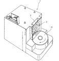
本発明の実施例を図面に基づいて説明すると、本実施例の握り玉整形装置1は、図1に示すように、上部に設置される撹拌装置(図示略)から開口部2に供給された米飯を圧縮しながら下方に送り出す搬送機構3が設けられている。
An embodiment of the present invention will be described with reference to the drawings. A gripping
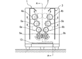
搬送機構3は、図2及び図3に示すように、離間して配置された3対の搬送ローラ4a、4b、5a、5b、6a、6bからなり、下方に設けられたものほど、その離間幅が狭くなるように配置されている。
As shown in FIGS. 2 and 3, the
これら搬送ローラ4a、4b、5a、5b、6a、6bは、駆動モータ7の駆動により図2中矢印方向に回転するようになっており、搬送ローラ4a、4b、5a、5b、6a、6bの回転により、開口部2から供給された米飯が徐々に圧縮されつつ下方に搬送されるようになっている。尚、図2中の8は、駆動モータ7の動力を搬送ローラ4a、4b、5a、5b、6a、6bに伝達するための伝達ギアである。
These
搬送ローラ4a、4b、5a、5b、6a、6bのうち最も下部に配置された搬送ローラ6a、6bの下方には、図2及び図3に示すように、1対の整形ローラ9a、9bが、その周面10、10が互いに当接するように配置されている。
A pair of
これら1対の整形ローラ9a、9bは、駆動モータ11の駆動により図2中左側の整形ローラ9aが時計回りに、図2中右側の整形ローラ9bが反時計回りに同期して回転するようになっている。すなわち各々が内側に向かって同期回転するようになっている。
The pair of
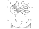
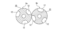
また、1対の整形ローラ9a、9bの周面10、10には、図4(a)(b)に示すように、回転軸方向に長い略半球状の凹部12が各々3つ等間隔に形成されており、回転時に互いの凹部12同士が対向するように配置されている。
Further, on the
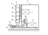
整形ローラ9a、9bの下方には、ターンテーブル13が設けられている。ターンテーブル13の回転軸にはプーリー13’が設けられている。そして、プーリー13’と整形ローラ9bの回転軸に設けられたプーリー9b’間に架けられた伝達ベルト14を介して駆動モータ11の動力が伝達され、ターンテーブル13が図1中矢印方向に回転するようになっている。すなわちターンテーブル13は、整形ローラ9a、9bの回転に連動して回転するようになっている。
A
次に、本実施例の握り玉整形装置1の動作状況について説明する。
Next, the operation state of the gripping
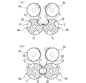
まず、図5(a)に示すように、整形ローラ9a、9bの凹部12、12が上方で向き合う状態となったときに、搬送ローラ4a、4b、5a、5b、6a、6bを回転させて定量分の米飯を送り出す。これにより、米飯が整形ローラ9a、9bの凹部12、12内に送り出される。
First, as shown in FIG. 5A, when the
次いで、搬送ローラ4a、4b、5a、5b、6a、6bの回転を停止して、整形ローラ9a、9bを回転させる。これに伴い、図5(b)に示すように、整形ローラ9aの凹部12の内面により内側の米飯が整形ローラ9bの凹部12側に押圧され、整形ローラ9bの凹部12の内面により内側の米飯が整形ローラ9aの凹部12側に押圧される。すなわち双方の整形ローラ9a、9bの凹部12、12の内面により米飯が圧縮される。また、前述のように凹部12、12は、回転軸方向に長い略半球状に形成されているので、双方の凹部12、12から圧縮されることで、内部の米飯が細長い球状、すなわち握り玉状に整形される。
Next, the rotation of the
また、整形ローラ9a、9bが図6(a)の位置まで回転した時点で、整形ローラ9a、9bの周面10、10同士が当接した状態となり、搬送機構3から送り出された米飯と整形ローラ9a、9bの凹部12、12により握り玉状に整形された米飯とが切り分けられる。すなわち整形ローラ9a、9bの周面10、10同士の当接により搬送機構3から送り出された定量分の米飯が切り分けられることとなる。
Further, when the
更に、図6(b)に示すように、整形ローラ9a、9bが回転することで整形ローラ9a、9bの凹部12、12内面により握り玉状の米飯が押し出されるとともに、米飯自体の重みにより下方のターンテーブル13上に落下するようになっている。
Further, as shown in FIG. 6 (b), when the shaping
また、凹部12、12が図5(a)に示す位置となった時点で整形ローラ9a、9bの回転を停止し、これらの動作を繰り返すことにより、搬送機構3から送り出された米飯が順次定量分の握り玉状に整形されるようになっている。
Further, when the
以上説明したように、本実施例の握り玉整形装置1では、整形ローラ9a、9bを回転させるのみで、整形ローラ9a、9bの凹部12、12内に送り出された米飯が双方の凹部12、12の内面により圧縮されて握り玉状に整形されるとともに、整形ローラ9a、9bの周面10、10同士が当接して凹部12、12内の整形された米飯、すなわち定量分の米飯が切り離されるので、簡単な構成にて定量分の握り玉を整形することができる。
As described above, in the gripping
また、本実施例では、整形ローラ9aの凹部12内面が整形ローラ9bの凹部12内の米飯を圧縮する圧縮面として機能し、整形ローラ9bの凹部12内面が整形ローラ9aの凹部12内の米飯を圧縮する圧縮面として機能するとともに、整形ローラ9aの周面10が整形ローラ9bの周面10に当接する当接面として機能し、整形ローラ9bの周面10が整形ローラ9aの周面10に当接する当接面として機能する。すなわち整形ローラ9a、9bはともに本発明の整形ローラ及び整形部材として機能する。これにより、凹部12、12内の米飯を均一な力で圧縮できるので、整形された米飯の食感を均一化することができるとともに、左右対象の凹部12、12にて圧縮されるので、見栄えの良い握り玉を整形できる。更に、凹部12の深さを浅く形成してもボリュームのある握り玉状に整形できるので、凹部12から米飯が離脱し易い。
In this embodiment, the inner surface of the
また、本実施例では、整形ローラ9a、9bの周面10、10に各々複数(本実施例では3つ)の凹部12が形成されており、整形ローラ9a、9bの1回の回転で複数の握り玉を整形できるので、整形ローラ9a、9bの回転速度を上げなくとも短時間で多くの握り玉を整形できる。
In this embodiment, a plurality of (three in this embodiment) recesses 12 are formed on the
また、本実施例では、整形ローラ9a、9bの回転に連動して回転するターンテーブル13が設けられており、以前に整形されてターンテーブル13上に落下した米飯が整形ローラ9a、9bの回転に伴い整形ローラ9a、9bの下方から移動するので、新たに整形された米飯が以前に整形された米飯の上に重なってしまうことを防止できる。
In the present embodiment, a
また、本実施例では、搬送機構3が定量分の米飯を送り出した後停止するので、搬送機構3から余分に米飯が送り出されて整形ローラ9a、9bの周面10、10の間に巻き込まれてしまうことを防止できる。
Further, in this embodiment, since the
以上、本発明の実施例を図面により説明してきたが、具体的な構成はこれら実施例に限られるものではなく、本発明の要旨を逸脱しない範囲における変更や追加があっても本発明に含まれる。 Although the embodiments of the present invention have been described with reference to the drawings, the specific configuration is not limited to these embodiments, and modifications and additions within the scope of the present invention are included in the present invention. It is.
例えば、前述の実施例では、1対の整形ローラ9a、9bの周面10、10同士が当接して配置され、これら1対の整形ローラ9a、9bを互いの凹部12、12が同時期に対向するように配置されているが、図7に示すように、1対の整形ローラ9a、9bを互いの凹部12、12が同時期に対向しないように、すなわち互いの凹部12、12をずれた位置に配置する構成としても良く、このようにすれば、整形ローラ9aの周面が整形ローラ9bの凹部12内の飯を圧縮する圧縮面及び整形ローラ9bの周面10と当接する当接面として機能するとともに、整形ローラ9bの周面が整形ローラ9aの凹部12内の飯を圧縮する圧縮面及び整形ローラ9aの周面10と当接する当接面として機能し、整形ローラ9aの凹部12と整形ローラ9bの凹部12とで別個に握り玉状の米飯を整形できるので、短時間で多くの握り玉を整形できる。
For example, in the above-described embodiment, the
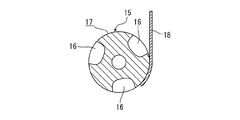
また、図8に示すように、搬送機構3の下方に回転軸方向に長い略半球状の凹部16が周面17に形成された整形ローラ15とその周面17に当接する整形板18(整形部材)を設けた構成としても良く、このようにした場合でも、整形ローラ15を回転することで搬送機構3から送り出された凹部16内の米飯が整形板18により圧縮され、細長い半球状の握り玉に整形されるとともに、整形ローラ15の周面17と整形板18が当接して凹部16内の整形された米飯が切り離されるので、簡単な構成にて定量分の握り玉を整形することができる。
Further, as shown in FIG. 8, a substantially hemispherical
また、図9に示すように、整形ローラ9a、9bの凹部12、12や整形ローラ15の凹部16の底面と底面部18の間に付勢部材19を取り付けて、底面部18が外方に向かって付勢されるようにしても良く、このようにすれば、凹部内の米飯を適度な力で圧縮できるとともに、整形された米飯の凹部からの離脱を補助することができる。
Further, as shown in FIG. 9, a biasing
また、前述の実施例では、整形する握り玉として握り寿司に用いるしゃり玉を想定しているため、整形ローラ9a、9bの凹部12、12や整形ローラ15の凹部16が回転軸方向に長い半球状に形成されたものを例示しているが、例えば、握り玉の用途に合わせてこれら整形ローラの凹部を直方体状や半円筒状、半球状等、適宜に変更したものでも良い。
Further, in the above-described embodiment, since the sushi balls used for nigiri sushi are assumed as the noodle balls to be shaped, the
また、前述の実施例では、搬送機構3が下方に米飯を搬送する構成としているが、例えば、ベルトコンベア等により、横方向に搬送し、搬送方向側に整形ローラ及び整形部材を設けても良い。
In the above-described embodiment, the
1 握り玉整形装置
2 開口部
3 搬送機構
9a、9b 整形ローラ
10 周面
12 凹部
DESCRIPTION OF
Claims (5)
飯を所定の方向に送り出す搬送機構を備え、
周面に凹部が形成された整形ローラと、
前記搬送機構により前記整形ローラの凹部内に送り出された飯を該整形ローラの回転に伴い圧縮する圧縮面と前記整形ローラの周面に当接する当接面が形成された整形部材と、
が前記搬送機構の送り出し側に設けられていることを特徴とする握り玉整形装置。 A grip ball shaping device for shaping rice into a ball shape,
It has a transport mechanism that sends out rice in a predetermined direction,
A shaping roller having a recess formed in the peripheral surface;
A shaping member formed with a compression surface that compresses the rice fed into the concave portion of the shaping roller by the conveying mechanism and a contact surface that comes into contact with the circumferential surface of the shaping roller;
Is provided on the delivery side of the transport mechanism.
前記整形部材が前記整形ローラにて構成されていることを特徴とする請求項1に記載の握り玉整形装置。 The peripheral surfaces of the pair of shaping rollers are arranged in contact with each other, and the pair of shaping rollers are rotated in opposite directions so that the respective concave portions face each other at the same time,
The gripping ball shaping device according to claim 1, wherein the shaping member is configured by the shaping roller.
前記整形部材が前記整形ローラにて構成されていることを特徴とする請求項1に記載の握り玉整形装置。 The peripheral surfaces of the pair of shaping rollers are arranged in contact with each other, and the pair of shaping rollers are rotated in opposite directions so that the respective concave portions do not face each other at the same time,
The gripping ball shaping device according to claim 1, wherein the shaping member is configured by the shaping roller.
Priority Applications (1)
| Application Number | Priority Date | Filing Date | Title |
|---|---|---|---|
| JP2004194529A JP2006014635A (en) | 2004-06-30 | 2004-06-30 | Rice-ball forming device |
Applications Claiming Priority (1)
| Application Number | Priority Date | Filing Date | Title |
|---|---|---|---|
| JP2004194529A JP2006014635A (en) | 2004-06-30 | 2004-06-30 | Rice-ball forming device |
Publications (1)
| Publication Number | Publication Date |
|---|---|
| JP2006014635A true JP2006014635A (en) | 2006-01-19 |
Family
ID=35789420
Family Applications (1)
| Application Number | Title | Priority Date | Filing Date |
|---|---|---|---|
| JP2004194529A Pending JP2006014635A (en) | 2004-06-30 | 2004-06-30 | Rice-ball forming device |
Country Status (1)
| Country | Link |
|---|---|
| JP (1) | JP2006014635A (en) |
Cited By (5)
| Publication number | Priority date | Publication date | Assignee | Title |
|---|---|---|---|---|
| JP2012029617A (en) * | 2010-07-30 | 2012-02-16 | Audio Technica Corp | Apparatus for molding cooked rice and method of controlling the same |
| JP2012152150A (en) * | 2011-01-27 | 2012-08-16 | Audio Technica Corp | Cooked rice molding apparatus |
| JP2013138651A (en) * | 2011-12-29 | 2013-07-18 | Fuji Seiki Co Ltd | Rice ball-molding apparatus |
| CN104957739A (en) * | 2015-07-13 | 2015-10-07 | 王国良 | Automatic ball production device |
| CN105310097A (en) * | 2015-07-29 | 2016-02-10 | 浙江海洋学院 | Processing device for hairtail prepared food |
Citations (5)
| Publication number | Priority date | Publication date | Assignee | Title |
|---|---|---|---|---|
| JPS6147160A (en) * | 1984-08-10 | 1986-03-07 | Audio Technica Corp | Food molding machine |
| JPS61202665A (en) * | 1985-03-07 | 1986-09-08 | Audio Technica Corp | Food forming machine |
| JPH1156274A (en) * | 1997-08-21 | 1999-03-02 | Makoto Suzuki | Apparatus for molding food |
| JPH11206330A (en) * | 1998-01-22 | 1999-08-03 | Ex Systems:Kk | Apparatus for forming food |
| JP2006000026A (en) * | 2004-06-16 | 2006-01-05 | Audio Technica Corp | Cooked rice forming device |
-
2004
- 2004-06-30 JP JP2004194529A patent/JP2006014635A/en active Pending
Patent Citations (5)
| Publication number | Priority date | Publication date | Assignee | Title |
|---|---|---|---|---|
| JPS6147160A (en) * | 1984-08-10 | 1986-03-07 | Audio Technica Corp | Food molding machine |
| JPS61202665A (en) * | 1985-03-07 | 1986-09-08 | Audio Technica Corp | Food forming machine |
| JPH1156274A (en) * | 1997-08-21 | 1999-03-02 | Makoto Suzuki | Apparatus for molding food |
| JPH11206330A (en) * | 1998-01-22 | 1999-08-03 | Ex Systems:Kk | Apparatus for forming food |
| JP2006000026A (en) * | 2004-06-16 | 2006-01-05 | Audio Technica Corp | Cooked rice forming device |
Cited By (5)
| Publication number | Priority date | Publication date | Assignee | Title |
|---|---|---|---|---|
| JP2012029617A (en) * | 2010-07-30 | 2012-02-16 | Audio Technica Corp | Apparatus for molding cooked rice and method of controlling the same |
| JP2012152150A (en) * | 2011-01-27 | 2012-08-16 | Audio Technica Corp | Cooked rice molding apparatus |
| JP2013138651A (en) * | 2011-12-29 | 2013-07-18 | Fuji Seiki Co Ltd | Rice ball-molding apparatus |
| CN104957739A (en) * | 2015-07-13 | 2015-10-07 | 王国良 | Automatic ball production device |
| CN105310097A (en) * | 2015-07-29 | 2016-02-10 | 浙江海洋学院 | Processing device for hairtail prepared food |
Similar Documents
| Publication | Publication Date | Title |
|---|---|---|
| MX2008002195A (en) | Systems and methods for providing an improved timing conveyor. | |
| WO2019167864A1 (en) | Conveyor device and conveying-direction changing device | |
| US20170129714A1 (en) | Conveyed-object discharge device | |
| JP2006014635A (en) | Rice-ball forming device | |
| JP2001163439A (en) | Carrying direction switching device in roller conveyor | |
| US5320575A (en) | Machine for automatically cutting shells of crab legs | |
| KR200321320Y1 (en) | meat cutter which cuts meat into cubic-shape | |
| WO2006022482A1 (en) | Noodles manufacturing apparatus | |
| JP2003070432A (en) | Apparatus for molding cooked rice | |
| JP2015231884A (en) | Bread turnover device and bread conveyance system | |
| JP2007105014A (en) | Apparatus for producing rice ball | |
| KR20060025725A (en) | Rice cake and confectionery of material a automatic cutting machine | |
| JP2010124710A (en) | Sheet-like vinegared rice feeding device | |
| JP3203709U (en) | Deformed steel plate conveyor | |
| CN204546601U (en) | A kind of food cutting cutter transmitting section interlock | |
| JPH11206330A (en) | Apparatus for forming food | |
| CN204546600U (en) | A kind of slicer transmitting section interlock | |
| JP6957060B1 (en) | Parts supply equipment | |
| KR100813488B1 (en) | Apparatus for thinly cutting of food | |
| JP3088715B1 (en) | Obi type sushi ball molding machine | |
| JP2021178379A (en) | Triple slicer | |
| JP2007308274A (en) | Conveying device | |
| US20070137392A1 (en) | Intermittent linear movement control device | |
| KR100476306B1 (en) | Centerless Front Guide for Peeling Machine | |
| JPH05304932A (en) | Feeder of raw rod-like food material for slice device |
Legal Events
| Date | Code | Title | Description |
|---|---|---|---|
| A621 | Written request for application examination |
Free format text: JAPANESE INTERMEDIATE CODE: A621 Effective date: 20070507 |
|
| A977 | Report on retrieval |
Free format text: JAPANESE INTERMEDIATE CODE: A971007 Effective date: 20090928 |
|
| A131 | Notification of reasons for refusal |
Free format text: JAPANESE INTERMEDIATE CODE: A131 Effective date: 20100202 |
|
| A02 | Decision of refusal |
Free format text: JAPANESE INTERMEDIATE CODE: A02 Effective date: 20100601 |