JP2006014228A - Communication method, communication system, station side communication apparatus and subscriber side communication apparatus - Google Patents
Communication method, communication system, station side communication apparatus and subscriber side communication apparatus Download PDFInfo
- Publication number
- JP2006014228A JP2006014228A JP2004192046A JP2004192046A JP2006014228A JP 2006014228 A JP2006014228 A JP 2006014228A JP 2004192046 A JP2004192046 A JP 2004192046A JP 2004192046 A JP2004192046 A JP 2004192046A JP 2006014228 A JP2006014228 A JP 2006014228A
- Authority
- JP
- Japan
- Prior art keywords
- side communication
- communication device
- redundancy
- fec
- unit
- Prior art date
- Legal status (The legal status is an assumption and is not a legal conclusion. Google has not performed a legal analysis and makes no representation as to the accuracy of the status listed.)
- Pending
Links
Images


Abstract
Description
この発明は、加入者側通信装置と局側通信装置が接続される通信システムにおける符号誤り訂正技術に関するものである。 The present invention relates to a code error correction technique in a communication system in which a subscriber side communication apparatus and a station side communication apparatus are connected.
マルチメディアサービスを各家庭まで伝送する従来のアクセス系ネットワークとして、PON(Passive Optical Network)システムが知られている(例えば非特許文献1参照)。このPONシステムは、複数の加入者側通信装置(ONU:Optical Network Unit)と局側通信装置(OLT:Optical Line Terminal)がスターカプラを介して光ファイバケーブルで接続されるものであり、複数のONUが単一のOLTを共有するため、経済的である。
一方、FEC(Forward Error Correction)等のエラー処理により、高品質なデータ再生を可能とするデータ通信システムにおける従来の通信方法として、往復伝播遅延(RTT:Round Trip Time)が短いならば、再送要求処理によるエラー訂正を選択し、RTTが長い状況である場合には、FECによるエラー訂正を選択するといった動的なエラー訂正制御が知られている(特許文献1参照)。
As a conventional access network for transmitting multimedia services to each home, a PON (Passive Optical Network) system is known (see, for example, Non-Patent Document 1). In this PON system, a plurality of subscriber side communication devices (ONU: Optical Network Unit) and a station side communication device (OLT: Optical Line Terminal) are connected via an optical fiber cable via a star coupler. It is economical because ONUs share a single OLT.
On the other hand, as a conventional communication method in a data communication system that enables high-quality data reproduction by error processing such as FEC (Forward Error Correction), if a round trip time (RTT) is short, a retransmission request is made. There is known a dynamic error correction control in which error correction by processing is selected and when the RTT is long, error correction by FEC is selected (see Patent Document 1).
特許文献1に開示された従来の通信方法においては、RTTの長短に基づいてFECを適用するか否かを制御するだけなので、例えば非特許文献1に開示されたPONシステムにFECを適用する場合には、同一のPONシステムに接続される全てのONUについてFEC強度が一定となる。このため、接続距離の異なるONUが混在するPONシステムにおいて、最遠端のONUに合わせたFEC強度が必要となり、近端のONUにおいては不必要に長いFEC冗長コードが付加され、伝送効率が低下するという問題点があった。
The conventional communication method disclosed in
この発明は、上述のような課題を解決するためになされたもので、通信方法において、例えばPONシステムにFEC技術を適用する場合に、OLTとONUとの接続距離に応じて、伝送効率を最適化することを目的としている。 The present invention has been made to solve the above-described problems. In the communication method, for example, when the FEC technology is applied to the PON system, the transmission efficiency is optimized according to the connection distance between the OLT and the ONU. The purpose is to become.
この発明に係る通信方法は、加入者側通信装置と局側通信装置との間の往復伝播遅延に基づいて、前記加入者側通信装置と前記局側通信装置との間の通信データに付加される符号誤り訂正符号における冗長度を前記加入者側通信装置毎に制御する冗長度制御工程を備えるものである。 The communication method according to the present invention is added to communication data between the subscriber side communication device and the station side communication device based on a round trip propagation delay between the subscriber side communication device and the station side communication device. A redundancy control step of controlling the redundancy in the code error correction code for each subscriber-side communication device.
この発明は、通信方法において、往復伝播遅延に対応するOLTとONUの接続距離に応じたFEC強度(冗長度)で通信を行うことができる。これにより、ONUの接続距離に応じて、伝送効率を最適化することができる。 According to the present invention, in the communication method, communication can be performed with the FEC strength (redundancy) corresponding to the connection distance between the OLT and the ONU corresponding to the round trip propagation delay. Thereby, the transmission efficiency can be optimized according to the connection distance of the ONU.
実施の形態1.
この発明の実施の形態1による通信方法は、複数の加入者側通信装置(ONU:Optical Network Unit)と局側通信装置(OLT:Optical Line Terminal)との間の往復伝播遅延(RTT:Round Trip Time)に基づいて、通信データに付加されるFEC(Forward Error Correction)冗長コード(符号誤り訂正符号)における冗長度をONU毎に制御するようにしているので、GE−PON(Giga bit Ethernet(登録商標)−Passive Optical Network)システムにFEC技術を適用する場合に、往復伝播遅延に対応するOLTとONUの接続距離に応じたFEC強度(冗長度)で通信を行うことができるものである。
The communication method according to the first embodiment of the present invention includes a round trip propagation delay (RTT) between a plurality of subscriber side communication devices (ONU: Optical Network Unit) and a station side communication device (OLT: Optical Line Terminal). Since the redundancy in the FEC (Forward Error Correction) redundancy code (code error correction code) added to the communication data is controlled for each ONU based on (Time), GE-PON (Giga bit Ethernet (registration) (Trademark) -Passive Optical Network) When the FEC technology is applied to the system, communication can be performed with the FEC strength (redundancy) corresponding to the connection distance between the OLT and the ONU corresponding to the round-trip propagation delay.
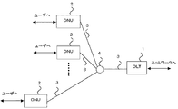
図1はこの発明の実施の形態1による通信方法におけるネットワークシステムを示す構成図である。図において、1は局側通信装置(OLT:Optical Line Terminal)、2は加入者側通信装置(ONU:Optical Network Unit)、3は光ファイバ、4は光カプラ(スターカプラ)である。ここで、複数のONU2は、光ファイバ3と光カプラ4を介してひとつのOLT1と接続され、PON(Passive Optical Network)システムが構成される。このようなPONシステムにおいては、接続距離の異なる複数のONUが混在する。
1 is a block diagram showing a network system in a communication method according to
図2はこの発明の実施の形態1による通信方法における局側通信装置を示す構成図である。図において、OLT1は、光電気変換部101、ビット同期部102、8B/10B変換部103、FEC(Forward Error Correction)符号化復号化部104、制御フレーム抽出部105、制御フレーム挿入部106、制御フレーム終端部107、PON制御部108、フレームバッファ109を備える。なお、FEC符号化復号化部104とPON制御部108とで冗長度制御部を構成する。
FIG. 2 is a block diagram showing a station side communication apparatus in the communication method according to
図3はこの発明の実施の形態1による通信方法における加入者側通信装置を示す構成図である。図において、ONU2は、光電気変換部201、ビット同期部202、8B/10B変換部203、FEC符号化復号化部204、制御フレーム挿入部205、制御フレーム抽出部206、制御フレーム終端部207、PON制御部208、フレームバッファ209を備える。なお、FEC符号化復号化部204とPON制御部208とで冗長度制御部を構成する。
FIG. 3 is a block diagram showing a subscriber side communication apparatus in the communication method according to
次に動作について説明する。
IEEE(Institute of Electrical and Electronics Engineers)802.3ahに規定されているように、まず、オートディスカバリにおけるレンジングを行う。なお、オートディスカバリとは、PON上で電源ONにより動作可能となったONUを登録するため、OLTがONUを検出するための機能である。
Next, the operation will be described.
First, ranging in auto-discovery is performed as specified in IEEE (Institute of Electrical and Electronics Engineers) 802.3ah. Auto-discovery is a function for the OLT to detect an ONU in order to register an ONU that has become operable when the power is turned on on the PON.
図4にオートディスカバリのシーケンスを示す。未登録ONU2では、Discovery GATEメッセージのみを受信する。それに対する応答としてRegister RequestメッセージをOLT1へ送信し、論理リンク確立を要求する。OLT1では、論理リンクリクエストに応じて論理リンクユーザ識別番号(LLID:Logical Link IDentification number)を予約する。そのLLIDをRegisterメッセージに入れてONU2へ通知する。その後、ONU2からのRegister ACKメッセージに対する上り帯域許可メッセージであるNormal GATEメッセージを送信する。ONU2ではその指定されたLLIDを設定し、Normal GATEに示されているタイミングでRegister ACKメッセージを送信する。OLT1でそのメッセージを受信した時点で論理リンク確立となる。
FIG. 4 shows an auto-discovery sequence. The unregistered ONU 2 receives only the Discovery GATE message. In response to this, a Register Request message is transmitted to the
一つのPONに接続される複数のONU2は、図1に示すようにOLT1から異なる距離に位置する。IEEE802.3ahで規定されるGE−PON(Gigabit Ethernet(登録商標)−Passive Optical Network)システムでは、OLTとONUとの距離に対応する往復伝播遅延(RTT:Round Trip Time)をOLTとONU間で通信する制御メッセージ(GATEとREPORT)に埋め込むタイムスタンプにより計測し、上りフレームを、このRTTを考慮して時分割多重制御する。
A plurality of
図5にRTT計測のシーケンスを示す。OLT1と各ONU2は、それぞれ32ビットのカウンタを有する。カウンタは主信号転送速度の2バイトごとにカウントアップする。これは、1.25Gbps(Gigabit per second)のGE−PONシステムの場合16nsに相当する。OLT1はこのカウンタを自立的にカウントアップし、GATEメッセージ送信時にカウンタの値をメッセージ内のタイムスタンプ領域に設定する(T1)。一方、ONU2はGATEメッセージを受信するとタイムスタンプの値をカウンタに設定する(T1)。つまりOLTが主、ONUが従となり、このGATE/REPORTメッセージを用いた手順を周期的に実施することでONUのオシレータ精度、伝播速度揺らぎ、同期ずれ等によるRTTの変動を補正する。
FIG. 5 shows an RTT measurement sequence. Each of the
ONU2は、REPORTメッセージ送信時にカウンタの値をメッセージ内のタイムスタンプ領域に設定する(T4)。OLTはREPORTメッセージを受信すると、REPORTメッセージ内のタイムスタンプ領域の値(T4)と、OLTがもつカウンタの値(T5)により、RTTを計測する(RTT=T5−T4)。 The ONU 2 sets the counter value in the time stamp area in the message when the REPORT message is transmitted (T4). When the OLT receives the REPORT message, the OLT measures the RTT based on the time stamp area value (T4) in the REPORT message and the counter value (T5) of the OLT (RTT = T5-T4).
次に、制御メッセージの通信手順を説明する。
OLT1のPON制御部108より制御メッセージ(例えば、Discovery GATEメッセージ)生成を制御フレーム終端部107に指示する。制御フレーム終端部107は、制御メッセージを生成する。制御フレーム挿入部106にて下り主信号フレームと多重し、FEC符号化復号化部104へ送信する。FEC符号化復号化部104においてFEC冗長コード(符号誤り訂正符号)を付加する。ここで、FEC冗長コードにおける冗長度(FEC冗長度)の初期値は最大冗長度設定とする。最大FEC冗長度であれば最遠端ONUであっても通信できる。FEC符号化復号化部104でFEC冗長コードを付加されたフレームは8B/10B変換部103にて10B変換後、光電気変換部にて光信号に変換して、ONU2へ送信する。
Next, a control message communication procedure will be described.
The control
ONU2では光電気変換部201にて光信号から電気信号に変換し、8B/10B変換部203にて8B変換後、メッセージフレームはFEC符号化復号化部204に送られる。FEC符号化復号化部204にてFEC復号化を行う。このときONU2のFEC冗長度の初期値は最大冗長度設定とする。FEC復号化されたメッセージフレームは、制御フレーム抽出部206にて主信号データフレームから抽出され、制御フレーム終端部207に送信される。制御フレーム終端部207ではフレームを解析し、PON制御部208へ必要な情報を通知する。
In the
一方、ONU2からの制御メッセージフレーム送信手順を以下に示す。ONU2のPON制御部208より制御メッセージ(例えば、Register Requestメッセージ)生成を制御フレーム終端部207に指示する。制御フレーム終端部207は、制御メッセージを生成する。制御フレーム挿入部205にて下り主信号フレームと多重し、FEC符号化復号化部204へ送信する。FEC符号化復号化部204においてFEC冗長コードを付加する。FEC冗長度の初期値は最大冗長度設定とする。FEC符号化復号化部204でFEC冗長コードを付加されたフレームは8B/10B変換部203にて10B変換後、光電気変換部201にて光信号に変換して、OLT1へ送信する。
On the other hand, a control message frame transmission procedure from the
OLT1では光電気変換部101にて光信号から電気信号に変換し、8B/10B変換部103にて8B変換後、メッセージフレームはFEC符号化復号化部104に送られる。FEC符号化復号化104にてFEC復号化を行う。このときONU2のFEC冗長度の初期値は最大冗長度設定とする。FEC復号化されたメッセージフレームは、制御フレーム抽出部105にて主信号データフレームから抽出され、制御フレーム終端部107に送信される。制御フレーム終端部107でフレームを解析し、PON制御部108へ必要な情報を通知する。
In the
次に、制御メッセージを用いたFEC冗長度制御の動作について説明する。
オートディスカバリ動作においてDiscovery GATEメッセージとRegister Requestメッセージの送受信において、上記GATEとREPORTメッセージ送受信の場合のようにRTTをOLT1が計測する。
Next, the operation of FEC redundancy control using a control message will be described.
In transmission / reception of Discovery GATE message and Register Request message in auto-discovery operation,
そのRTTに応じたFEC冗長度をOLT1にて選択し、Registerメッセージにて該当するONU2に通知する。OLT1のPON制御部108は論理リンク確立時に計測したそれぞれのONU2のRTTに対応するFEC冗長度をFEC符号化復号化部104に設定する。そして、そのONU2に対するフレームについては、設定したFEC冗長度で運用を行う。上りフレームについては、GE−PONシステムにおいてはPON制御部108が複数のONU2からのフレーム送信が衝突するのを回避するように帯域制御を行っており、どのONU2からのフレームかは、どのタイミングでOLT1が受信するかにより判断可能である。受信したフレームをそのONU2に対応するFEC冗長度で復号化する。
The FEC redundancy corresponding to the RTT is selected by the
一方、ONU2のPON制御部208は、OLT1よりRegisterメッセージにて該当するONU2に通知されたFEC冗長度をFEC符号化復号化部204に設定する。送信フレームについては、その設定されたFEC冗長度で符号化し、OLT1へGATEメッセージ内の情報に準じて送信する。受信フレームについては、設定されたFEC冗長度で復号化を行う。
On the other hand, the
以上のように、この発明の実施の形態1による通信方法においては、複数のONUとOLTとの間の往復伝播遅延に基づいて、通信データに付加されるFEC冗長コードにおける冗長度をONU毎に制御するようにしているので、GE−PONシステムにFEC技術を適用する場合に、往復伝播遅延に対応するOLTとONUの接続距離に応じたFEC強度(冗長度)で通信を行うことができる。これにより、ONUの接続距離に応じて、伝送効率を最適化することができる。
As described above, in the communication method according to
実施の形態2.
この発明の実施の形態2による通信方法は、複数の加入者側通信装置(ONU:Optical Network Unit)と局側通信装置(OLT:Optical Line Terminal)との間の往復伝播遅延に基づいて、接続距離に応じてFEC(Forward Error Correction)冗長度を制御するとともに、その冗長度に応じて通信速度をONU毎に制御することにより、GE−PON(Giga bit Ethernet(登録商標)−Passive Optical Network)システムにFEC技術を適用する場合に、ONUの接続距離に関係なく、伝送効率を一定に最適化することができるものである。
The communication method according to the second embodiment of the present invention is based on a round trip propagation delay between a plurality of subscriber side communication devices (ONU: Optical Network Unit) and a station side communication device (OLT: Optical Line Terminal). The FEC (Forward Error Correction) redundancy is controlled according to the distance, and the communication speed is controlled for each ONU according to the redundancy, so that GE-PON (Gigabit Ethernet (registered trademark) -Passive Optical Network). When the FEC technology is applied to the system, the transmission efficiency can be constantly optimized regardless of the ONU connection distance.
図6はこの発明の実施の形態2による通信方法における局側通信装置を示す構成図である。図において、OLT1は、光電気変換部101、ビット同期部102、8B/10B変換部103、FEC符号化復号化部104、制御フレーム抽出部105、制御フレーム挿入部106、制御フレーム終端部107、PON制御部108、フレームバッファ109、通信速度制御部としての速度調整部110を備える。なお、FEC符号化復号化部104とPON制御部108とで冗長度制御部を構成する。
6 is a block diagram showing a station side communication apparatus in a communication method according to
図7はこの発明の実施の形態2による通信方法における加入者側通信装置を示す構成図である。図において、ONU4は、光電気変換部201、ビット同期部202、8B/10B変換部203、FEC符号化復号化部204、制御フレーム挿入部205、制御フレーム抽出部206、制御フレーム終端部207、PON制御部208、フレームバッファ209、通信速度制御部としての速度調整部210を備える。なお、FEC符号化復号化部204とPON制御部208とで冗長度制御部を構成する。
FIG. 7 is a block diagram showing a subscriber side communication apparatus in a communication method according to
次に動作について説明する。
上記の実施の形態1と同様に、オートディスカバリ動作においてDiscovery GATEメッセージとRegister Requestメッセージの送受信において、GATEとREPORTメッセージ送受信の場合のようにRTTをOLT1が計測する。そして、そのRTTに応じたFEC冗長度を選択する。さらに、そのRTTに応じた受信/送信回路動作周波数(通信速度)を選択する。例えばRTTの値が大きければ(遠距離接続ONUの場合)、冗長度を上げなくてはならないので、FEC冗長コードが長くなりユーザデータ領域が小さくなり伝送効率が下がるため、受信/送信回路動作周波数(通信速度)を高く設定するようにする。
Next, the operation will be described.
Similar to the first embodiment, in the transmission / reception of the Discovery GATE message and the Register Request message in the auto-discovery operation, the
そのRTTに応じたFEC冗長度をOLT1にて選択し、Registerメッセージにて該当するONU2に通知する。OLT1のPON制御部108は論理リンク確立時に計測したそれぞれのONU2のRTTに対応するFEC冗長度をFEC符号化復号化部104に、また、それぞれのONU2のRTTに対応する回路動作周波数(通信速度)をビット同期部101、8B/10B変換部103、FEC符号化復号化部104、速度調整部110に設定する。そして、そのONU2に対する送信フレームについては、設定したFEC冗長度と通信速度で送信を行う。上りフレームについてはGE−PONシステムにおいてはOLT1が複数のONU2からのフレーム送信が衝突するのを回避するように帯域制御を行っており、どのONU2からのフレームかどうかは、どのタイミングでOLT1が受信するかにより判断可能である。受信したフレームをそのONU2に対応する回路動作周波数(通信速度)でビット同期部101、8B/10B変換部103、FEC符号化復号化部104、速度調整部110を動作させてフレームを受信し、そのONU2に対応するFEC冗長度で復号化する。
The FEC redundancy corresponding to the RTT is selected by the
一方、ONU2は、OLT1よりRegisterメッセージにて該当するONU2に通知されたFEC冗長度をFEC符号化復号化部204に、また、そのONU2のRTTに対応する回路動作周波数(通信速度)をビット同期部201、8B/10B変換部203、FEC符号化復号化部204、速度調整部210に設定する。送信フレームについては、その設定されたFEC冗長度と通信速度で、OLT1へGATEメッセージ内の情報に準じて送信する。受信フレームについては、設定された回路動作周波数(通信速度)でビット同期部201、8B/10B変換部203、FEC符号化復号化部204、速度調整部210を動作させてフレームを受信し、設定されたFEC冗長度で復号化を行う。
On the other hand, the
以上のように、この発明の実施の形態2による通信方法においては、複数のONUとOLTとの間の往復伝播遅延に基づいて、接続距離に応じてFEC冗長度を制御するとともに、その冗長度に応じて通信速度をONU毎に制御するようにしているので、GE−PONシステムにFEC技術を適用する場合に、ONUの接続距離に関係なく、伝送効率を一定に最適化することができる。 As described above, in the communication method according to the second embodiment of the present invention, the FEC redundancy is controlled according to the connection distance based on the round-trip propagation delay between the plurality of ONUs and the OLT, and the redundancy Therefore, when the FEC technique is applied to the GE-PON system, the transmission efficiency can be constantly optimized regardless of the connection distance of the ONU.
なお、上述のように、この発明の実施の形態1、2では、Ethernet(登録商標)のフレームを用いる場合を示したが、フレーム形式がこれに限られるものでなく、パケット通信に対応したものであれば良い。 As described above, in the first and second embodiments of the present invention, the case where an Ethernet (registered trademark) frame is used has been described. However, the frame format is not limited to this and is compatible with packet communication. If it is good.
また、この発明の実施の形態1、2では、PONシステムに適用する場合を示したが、適用システムがこれに限られるものでないことは言うまでもなく、複数の通信装置間で通信が行われるものであれば、光や電気の有線通信や、無線通信等どのようなシステムにも適用可能である。 In the first and second embodiments of the present invention, the case where the present invention is applied to the PON system is shown. Needless to say, the application system is not limited to this, and communication is performed between a plurality of communication devices. If so, the present invention can be applied to any system such as optical or electrical wired communication or wireless communication.
1 局側通信装置
2 加入者側通信装置
104、204 FEC符号化復号化部
108、208 PON制御部
110、210 速度調整部
DESCRIPTION OF
Claims (6)
Priority Applications (1)
| Application Number | Priority Date | Filing Date | Title |
|---|---|---|---|
| JP2004192046A JP2006014228A (en) | 2004-06-29 | 2004-06-29 | Communication method, communication system, station side communication apparatus and subscriber side communication apparatus |
Applications Claiming Priority (1)
| Application Number | Priority Date | Filing Date | Title |
|---|---|---|---|
| JP2004192046A JP2006014228A (en) | 2004-06-29 | 2004-06-29 | Communication method, communication system, station side communication apparatus and subscriber side communication apparatus |
Publications (1)
| Publication Number | Publication Date |
|---|---|
| JP2006014228A true JP2006014228A (en) | 2006-01-12 |
Family
ID=35780866
Family Applications (1)
| Application Number | Title | Priority Date | Filing Date |
|---|---|---|---|
| JP2004192046A Pending JP2006014228A (en) | 2004-06-29 | 2004-06-29 | Communication method, communication system, station side communication apparatus and subscriber side communication apparatus |
Country Status (1)
| Country | Link |
|---|---|
| JP (1) | JP2006014228A (en) |
Cited By (9)
| Publication number | Priority date | Publication date | Assignee | Title |
|---|---|---|---|---|
| JP2007104571A (en) * | 2005-10-07 | 2007-04-19 | Sumitomo Electric Ind Ltd | Optical line terminal and optical network unit in optical communication system |
| JP2008085708A (en) * | 2006-09-28 | 2008-04-10 | Mitsubishi Electric Corp | Transmitter and communication system |
| JP2009112050A (en) * | 2009-01-28 | 2009-05-21 | Hitachi Communication Technologies Ltd | Method of correcting error in transmission signal in optical access system |
| JP2010500796A (en) * | 2006-08-11 | 2010-01-07 | ホアウェイ・テクノロジーズ・カンパニー・リミテッド | Forward error correction for 64B66B coding system |
| US7978972B2 (en) | 2006-12-13 | 2011-07-12 | Hitachi, Ltd. | Optical line terminal and optical network terminal |
| US8078929B2 (en) | 2006-08-30 | 2011-12-13 | Hitachi, Ltd. | Optical line terminal and optical network terminal |
| JP2012134933A (en) * | 2010-12-24 | 2012-07-12 | Of Networks:Kk | Master station communication device, slave station communication device, optical communication network system, and communication method |
| US8457492B2 (en) | 2009-05-25 | 2013-06-04 | Hitachi, Ltd. | Optical access system |
| EP1971057A3 (en) * | 2007-03-15 | 2016-06-15 | Fujitsu Limited | Passive optical network and method of data transmission in the passive optical network |
Citations (10)
| Publication number | Priority date | Publication date | Assignee | Title |
|---|---|---|---|---|
| JPH05276144A (en) * | 1991-11-15 | 1993-10-22 | Nec Corp | Tdma system light transmission system |
| JPH09191317A (en) * | 1995-09-22 | 1997-07-22 | Alcatel Nv | Method for measuring signal transmission delay time, central station to execute this method, terminal station and network |
| JPH10276178A (en) * | 1997-03-31 | 1998-10-13 | Fujitsu Ten Ltd | Data transmitting device and method |
| JPH11261617A (en) * | 1998-03-09 | 1999-09-24 | Fujitsu Ltd | Optical subscriber network and delay mesurement method therefor |
| WO2002030074A1 (en) * | 2000-10-03 | 2002-04-11 | Marconi Communications Spa | Eye-diagram mask for optical pulses |
| JP2003188855A (en) * | 2001-12-19 | 2003-07-04 | Nec Mobiling Ltd | Error correction control system of mobile communication |
| JP2003273841A (en) * | 2002-03-15 | 2003-09-26 | Fujitsu Ltd | Transmission device provided with error correction function |
| WO2003092207A1 (en) * | 2002-04-25 | 2003-11-06 | Passave, Inc. | Forward error correction coding in ethernet networks |
| JP2004364059A (en) * | 2003-06-05 | 2004-12-24 | Matsushita Electric Ind Co Ltd | System and method for communication |
| JP2006510311A (en) * | 2002-12-16 | 2006-03-23 | パッセイヴ リミテッド | Method of initialization and auto-negotiation of Ethernet frame forward error correction |
-
2004
- 2004-06-29 JP JP2004192046A patent/JP2006014228A/en active Pending
Patent Citations (10)
| Publication number | Priority date | Publication date | Assignee | Title |
|---|---|---|---|---|
| JPH05276144A (en) * | 1991-11-15 | 1993-10-22 | Nec Corp | Tdma system light transmission system |
| JPH09191317A (en) * | 1995-09-22 | 1997-07-22 | Alcatel Nv | Method for measuring signal transmission delay time, central station to execute this method, terminal station and network |
| JPH10276178A (en) * | 1997-03-31 | 1998-10-13 | Fujitsu Ten Ltd | Data transmitting device and method |
| JPH11261617A (en) * | 1998-03-09 | 1999-09-24 | Fujitsu Ltd | Optical subscriber network and delay mesurement method therefor |
| WO2002030074A1 (en) * | 2000-10-03 | 2002-04-11 | Marconi Communications Spa | Eye-diagram mask for optical pulses |
| JP2003188855A (en) * | 2001-12-19 | 2003-07-04 | Nec Mobiling Ltd | Error correction control system of mobile communication |
| JP2003273841A (en) * | 2002-03-15 | 2003-09-26 | Fujitsu Ltd | Transmission device provided with error correction function |
| WO2003092207A1 (en) * | 2002-04-25 | 2003-11-06 | Passave, Inc. | Forward error correction coding in ethernet networks |
| JP2006510311A (en) * | 2002-12-16 | 2006-03-23 | パッセイヴ リミテッド | Method of initialization and auto-negotiation of Ethernet frame forward error correction |
| JP2004364059A (en) * | 2003-06-05 | 2004-12-24 | Matsushita Electric Ind Co Ltd | System and method for communication |
Cited By (11)
| Publication number | Priority date | Publication date | Assignee | Title |
|---|---|---|---|---|
| JP2007104571A (en) * | 2005-10-07 | 2007-04-19 | Sumitomo Electric Ind Ltd | Optical line terminal and optical network unit in optical communication system |
| JP4737528B2 (en) * | 2005-10-07 | 2011-08-03 | 住友電気工業株式会社 | Control station side apparatus and terminal station side apparatus in optical communication system |
| JP2010500796A (en) * | 2006-08-11 | 2010-01-07 | ホアウェイ・テクノロジーズ・カンパニー・リミテッド | Forward error correction for 64B66B coding system |
| US8122325B2 (en) | 2006-08-11 | 2012-02-21 | Futurewei Technologies, Inc. | Forward error correction for 64b66b coded systems |
| US8078929B2 (en) | 2006-08-30 | 2011-12-13 | Hitachi, Ltd. | Optical line terminal and optical network terminal |
| JP2008085708A (en) * | 2006-09-28 | 2008-04-10 | Mitsubishi Electric Corp | Transmitter and communication system |
| US7978972B2 (en) | 2006-12-13 | 2011-07-12 | Hitachi, Ltd. | Optical line terminal and optical network terminal |
| EP1971057A3 (en) * | 2007-03-15 | 2016-06-15 | Fujitsu Limited | Passive optical network and method of data transmission in the passive optical network |
| JP2009112050A (en) * | 2009-01-28 | 2009-05-21 | Hitachi Communication Technologies Ltd | Method of correcting error in transmission signal in optical access system |
| US8457492B2 (en) | 2009-05-25 | 2013-06-04 | Hitachi, Ltd. | Optical access system |
| JP2012134933A (en) * | 2010-12-24 | 2012-07-12 | Of Networks:Kk | Master station communication device, slave station communication device, optical communication network system, and communication method |
Similar Documents
| Publication | Publication Date | Title |
|---|---|---|
| JP4723940B2 (en) | COMMUNICATION SYSTEM AND COMMUNICATION METHOD, AND BASE STATION DEVICE AND SUBSTATION DEVICE | |
| US9112612B2 (en) | Relay device, station-side optical communication device, communication system, and bandwidth allocation method | |
| JP4558703B2 (en) | Burst data reception processing method and apparatus in Ethernet passive optical network | |
| US8126335B2 (en) | Methods and apparatus for next generation access passive optical networks | |
| KR101116719B1 (en) | Method and device for providing uplink burst data in passive optical network system | |
| JP2007174641A (en) | Tdma pon olt system for broadcasting service | |
| WO2007102303A1 (en) | Pon system and terminal operation registering method | |
| US20140193161A1 (en) | Enabling Communication Between Two End Terminals in a Fibre Optic Network | |
| US20180212705A1 (en) | Optical network unit registration method, apparatus, and system | |
| US8675870B2 (en) | Encryption apparatus | |
| WO2010091556A1 (en) | Method for burst transmission on a passive optical network, method and device for receiver resetting | |
| JP2006014228A (en) | Communication method, communication system, station side communication apparatus and subscriber side communication apparatus | |
| WO2012020450A1 (en) | Station-side apparatus and pon system | |
| WO2010096984A1 (en) | Method and device for transmitting an upstream transmission frame in a passive optical network | |
| JP2005333318A (en) | Station side apparatus and communication system | |
| CN106878834B (en) | Passive optical network compatible device and implementation method thereof and optical line terminal | |
| JP2007116587A (en) | Data transmission system | |
| CN115209245A (en) | Data transmission method, optical line terminal, optical network unit and communication system | |
| JP2009189026A5 (en) | ||
| JP2007281979A (en) | Pon (passive optical network) system | |
| KR100748093B1 (en) | Burst data reception method and apparatus in epon | |
| WO2024045814A1 (en) | Data transmission method, related device and optical communication system | |
| WO2024045812A1 (en) | Data transmission method, related equipment, and optical communication system | |
| JP2019022157A (en) | Subscriber line terminal apparatus | |
| Roy et al. | 10G-EPON efficiency |
Legal Events
| Date | Code | Title | Description |
|---|---|---|---|
| A621 | Written request for application examination |
Free format text: JAPANESE INTERMEDIATE CODE: A621 Effective date: 20070129 |
|
| A977 | Report on retrieval |
Free format text: JAPANESE INTERMEDIATE CODE: A971007 Effective date: 20090819 |
|
| A131 | Notification of reasons for refusal |
Effective date: 20090901 Free format text: JAPANESE INTERMEDIATE CODE: A131 |
|
| A521 | Written amendment |
Free format text: JAPANESE INTERMEDIATE CODE: A523 Effective date: 20091029 |
|
| A131 | Notification of reasons for refusal |
Effective date: 20100202 Free format text: JAPANESE INTERMEDIATE CODE: A131 |
|
| A521 | Written amendment |
Effective date: 20100331 Free format text: JAPANESE INTERMEDIATE CODE: A523 |
|
| A02 | Decision of refusal |
Free format text: JAPANESE INTERMEDIATE CODE: A02 Effective date: 20100706 |