JP2006009327A - Thermal insulation wall structure of building - Google Patents
Thermal insulation wall structure of building Download PDFInfo
- Publication number
- JP2006009327A JP2006009327A JP2004185709A JP2004185709A JP2006009327A JP 2006009327 A JP2006009327 A JP 2006009327A JP 2004185709 A JP2004185709 A JP 2004185709A JP 2004185709 A JP2004185709 A JP 2004185709A JP 2006009327 A JP2006009327 A JP 2006009327A
- Authority
- JP
- Japan
- Prior art keywords
- heat insulating
- insulating layer
- thermal insulation
- wall structure
- air
- Prior art date
- Legal status (The legal status is an assumption and is not a legal conclusion. Google has not performed a legal analysis and makes no representation as to the accuracy of the status listed.)
- Pending
Links
Images


Abstract
Description
本発明は、居住性を高めると同時に、冷暖房システムの負担を軽減し、省エネルギー化を図る、例えば、軸組構造による木造住宅などの建築物の断熱壁構造に関するものである。 The present invention relates to a heat insulating wall structure of a building such as a wooden house having a frame structure, for example, to improve the comfort and reduce the burden on an air conditioning system and save energy.
木造住宅などの建築物においては、快適な温湿度の居住空間を確保し、また、冷暖房のエネルギーを節約するため、建築物の全体を高断熱化し、高気密化することが普及している。この様な建築物の壁や屋根の内部には、グラスウールや発泡樹脂などの断熱材が配置され、また、外気を流通させて湿気を排出させる通気路が形成されている。
例えば、建築物の断熱壁構造として、基礎上に床とともに設けられる外壁を、内側の断熱層と、断熱層の外側に設ける外装材により構成し、該断熱壁と外装材との間に通気路を設け、通気路の下端から空気を導入して上方へ通気するものは従来より知られている(特許文献1参照)。
In a building such as a wooden house, in order to secure a comfortable living space with temperature and humidity and to save energy for air conditioning, it is widely used to make the entire building highly insulated and airtight. Inside such a building wall or roof, a heat insulating material such as glass wool or foamed resin is disposed, and an air passage is formed through which outside air is circulated and moisture is discharged.
For example, as a heat insulating wall structure of a building, an outer wall provided with a floor on a foundation is constituted by an inner heat insulating layer and an exterior material provided outside the heat insulating layer, and an air passage between the heat insulating wall and the outer material. In the prior art, there has been known that air is introduced from the lower end of the ventilation path and vented upward (see Patent Document 1).
また、基礎部および軸組部の屋外側に張り巡らされた断熱層と、この断熱層の室内側に配設された内装材と、前記断熱層と内装材との間に形成され、かつ室内空気を下方から上方へ通気させるための通気路とを備えたものも従来より知られている(特許文献2参照)。 And a heat insulating layer stretched on the outdoor side of the foundation portion and the shaft assembly, an interior material disposed on the indoor side of the heat insulating layer, and formed between the heat insulating layer and the interior material, and A thing provided with the ventilation path for ventilating air from the lower part to the upper part is also known conventionally (refer to patent documents 2).
しかし、上記した通気路および断熱層はそれぞれが単独であるために、室温と外気温の温度差による壁体内結露が発生し、特に熱伝導率の高いボルト等における結露は、その周りの木材を腐朽させて耐久性が悪くなり、シロアリ発生の要因にもなっている。
更に、断熱層が厚いために、それを固定するビス、釘類等の加重ストレスが大きく、経年劣化(金属疲労)による耐久性に問題点があった。
However, since the air passage and the heat insulating layer described above are each independent, condensation in the wall due to the temperature difference between the room temperature and the outside air temperature occurs, and in particular, condensation on bolts with high thermal conductivity is caused by the surrounding wood. It decays and becomes less durable, and it also causes termites.
Furthermore, since the heat insulating layer is thick, there is a problem in durability due to deterioration over time (metal fatigue) due to large load stress such as screws and nails for fixing the heat insulating layer.
本発明は、上記問題点を解決するため、その断熱性能を一層向上させる建築物の断熱壁構造を提供するものである。 In order to solve the above problems, the present invention provides a heat insulating wall structure for a building that further improves the heat insulating performance.
本発明は、断熱層と複数の通気路によって断熱壁を形成し、断熱層の屋外側には空気が上方へ流れる外通気路、断熱層の室内側には空気が下方へ流れる内通気路を設けた断熱壁構造を特徴とする。 In the present invention, a heat insulating wall is formed by a heat insulating layer and a plurality of air passages, an outer air passage through which air flows upward on the outdoor side of the heat insulating layer, and an internal air passage through which air flows downward on the indoor side of the heat insulating layer. It features a heat insulating wall structure provided.
また、上記断熱層は、基礎部および軸組部の屋外側に張設した外断熱層と、該外断熱層の室内側に密着する状態で軸組部に取り付けた内断熱層からなる断熱壁構造を特徴とする。 The heat insulating layer includes a heat insulating wall comprising an outer heat insulating layer stretched on the outdoor side of the base portion and the shaft assembly portion, and an inner heat insulating layer attached to the shaft assembly portion in close contact with the indoor side of the outer heat insulation layer. Characterized by structure.
本発明は、外断熱層の室内側に内断熱層を設けることにより外断熱層の厚みを薄くし、それによって、外断熱層を軸組部に固定するビス、釘類の加重ストレスの問題点を解決した。 The present invention reduces the thickness of the outer heat insulating layer by providing an inner heat insulating layer on the indoor side of the outer heat insulating layer, thereby causing a problem of weight stress of screws and nails to fix the outer heat insulating layer to the shaft assembly. Solved.
また、通気路と、その内側に設けた断熱層からなる従来の断熱壁に生じた壁体内結露や木材の腐朽等の問題点も、外通気路と内通気路からなる複数の通気路とし、更に、断熱層も、外断熱層と内断熱層を積層する二層構造にしたことによって解決することができた。断熱層は二層構造から成っているので、外断熱層が劣化した場合でも内断熱層により気密性を維持することができる。 In addition, problems such as dew condensation in the wall and decay of wood that occurred in the conventional heat insulating wall consisting of the air passage and the heat insulating layer provided on the inside are also a plurality of air passages consisting of the outer air passage and the inner air passage, Furthermore, the heat insulating layer can also be solved by adopting a two-layer structure in which the outer heat insulating layer and the inner heat insulating layer are laminated. Since the heat insulating layer has a two-layer structure, airtightness can be maintained by the inner heat insulating layer even when the outer heat insulating layer is deteriorated.
更に、二層構造からなる断熱層の室内側に設けた内通気路に空気を上方から下方へ流し、該空気を室内側の下部壁面に設けたグリルより居室内へ供給する構造としたことにより、結露の防止と共に居室内の空気を清浄化し、快適な居住空間を形成することができた。 Furthermore, the structure is such that air flows from the upper side to the lower side in the indoor ventilation path provided on the indoor side of the heat insulating layer having a two-layer structure, and the air is supplied to the living room from the grill provided on the lower wall surface on the indoor side. In addition to preventing condensation, the air in the living room was cleaned and a comfortable living space could be formed.
本発明の実施形態を図面に基いて以下説明する。 Embodiments of the present invention will be described below with reference to the drawings.
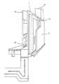
図1乃至図3は本発明の一実施の形態を示すもので、図1は、二層構造からなる断熱層1の屋外側に外通気路2を、室内側に内通気路3を形成した本発明の断熱壁構造を示す縦断面図であり、図2は、本発明の断熱壁構造の一部を斜めからみた断面斜視図で、図3は、本発明の断熱壁構造を水平面で切断した水平断面図を示すものである。
FIG. 1 to FIG. 3 show an embodiment of the present invention. FIG. 1 shows that an
図1乃至図4に示されるこの建築物は木造からなる建築物で、土台、柱、梁、桁、筋違いなどの軸組部4と、該軸組部4に取り付けた断熱層1と、該断熱層1の屋外側を覆う外壁材5と、該断熱層1の内側を覆い室内空間を形成する内装材6と、内装材6の上部に設けられた天井材7と、軸組部4の上部を覆う屋根組8と、外壁材5と断熱層1との間に設けられた外通気路2と、外通気路2と建築物外部とを連絡する外気取り入れ部9と、断熱層1と内装材6との間に設けられた内通気路3と、屋根裏空間部10と内通気路3とを連絡する空気取り入れ部11と、内通気路3に流れる空気を室内空間部12へ送り込む内装材6の下方に設けた開口部13とを備え、該屋根裏空間部10に全熱交換型換気扇(第一種換気)、家庭用エアコン等が、更に、一階床下には床暖房コンクリート蓄熱体が設置されている。
The building shown in FIGS. 1 to 4 is a wooden building, and includes a frame part 4 such as a base, a pillar, a beam, a girder, a streak, a heat insulating layer 1 attached to the frame part 4, An
外壁材5や屋根組8が日照などによって加温されると、外通気路2にドラフトが作用して外気取り入れ部9から外通気路2へ空気が流入し、矢印で示すように上方へ移動した後屋根裏空間部10の空気が通気設備から排気され、屋根裏空間部10と外通気路2の温度上昇を防いでいる。
When the
断熱層1は、軸組部4の屋外側に取り付けて外通気路2を形成する外断熱層1aと、該外断熱層1aの室内側に積層した状態で軸組部4に取り付けて内通気路3を形成する内断熱層1bの二層構造から成り、外断熱層1aの外側から押さえる外胴縁14と、外胴縁14を柱41、間柱42に固定する釘15等により、外断熱層1aが軸組部4に取り付けられる。
このようにして外断熱層1aを軸組部4の屋外側に取り付けた後、外胴縁14の外表面に外壁材5を取り付けることにより、外胴縁14がスペーサとなって、外断熱層1aと外壁材5との間に外通気路2が形成される。
The heat insulation layer 1 is attached to the shaft assembly 4 in a state of being laminated on the indoor side of the outer
After the outer
上記したように、断熱層1は二重構造から成っているので外断熱層1aは薄い断熱層となり、軸組部4に取り付ける際のビス、釘類等の加重ストレスが小さくなる。断熱層1を形成する材料としては、フェノール樹脂、硬質ウレタン等が使用される。また、外断熱層1aの屋外側には防水シート、室内側には気密シートによって被覆される。
As described above, since the heat insulating layer 1 has a double structure, the outer
次いで、内装材6を内断熱層1bの室内側へ間隔を設けて軸組部4に取り付けることにより、内断熱層1bと内装材6との間に内通気路3が形成される。内装材6は、内胴縁61と、それに取り付けた石膏ボード62、該石膏ボードの表面を覆う仕上げ材63により形成されている。
Next, the
屋根裏空間部10を利用して全熱交換型換気扇、家庭用エアコン等が設置されているので、夏季においては家庭用エアコンを稼働し、内通気路3を流れる冷たい下降気流を内装材6の下方に設けた開口部13から室内空間部12へ取り入れるという下降気流を利用したエアフレッシュ工法により、全室を自然に冷やすことができるので、室内に取り付けたエアコンが苦手である人にとっても家庭用エアコンを屋根裏空間部を利用して取り付けることにより健康的に涼をとることができ快適な居住空間になる。
Since a total heat exchange type exhaust fan, home air conditioner, etc. are installed using the
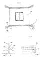
上記実施例で示した室内空間部12への空気取り入れ口は内装材6の下方に設けた開口部13であるが、図4で示されるように、室内空間部12を形成する壁面下部に設ける巾木16を上巾木16aと下巾木16bとに分割し、上下巾木間にスリット17を形成して取り付けることにより、下降気流を、該スリット17を通気口として室内へ給気することができる。
図4b、4cで示すように、下巾木16bは、土台の下方に設けた長尺材の桟木18に固定され、又、土台上方に固定される短尺材の桟木18’、更に、柱41と間柱42に固定される短尺材の内胴縁61’は、下降気流がスリット17を通して室内へ給気できるように、該短尺材の桟木を適宜の間隔で土台に、該内胴縁も適宜の間隔で柱と間柱にそれぞれ固定され、上巾木は、下巾木に対しスリットを設けるようにして、該桟木18’及び内胴縁61’に固定される。
上記実施例は、土台上方に取り付ける桟木18’及び内胴縁61’に短尺材を使用したが、長尺材に適宜の間隔で凹部を設けた桟木及び内胴縁を用い、下降気流が該凹部を通して通気口へ流れるようにしてもよい。
Although the air intake to the
As shown in FIGS. 4b and 4c, the
In the above embodiment, a short material is used for the pier 18 'and the inner trunk edge 61' attached above the base. You may make it flow into a vent hole through a recessed part.
気密性の高い建築物は一旦湿気が壁体内に侵入するとなかなか外部に排出されないために内部結露の原因になる恐れもあるが、本発明のように、上昇気流となる外通気路、下降気流となる内通気路によって、二層構造からなる断熱層を挟む断熱壁構造としてあるので内部結露が防ぐことができる。 In a highly airtight building, once moisture enters the wall, it is not easily exhausted to the outside, which may cause internal condensation. Since the inner air passage forms a heat insulating wall structure that sandwiches a heat insulating layer having a two-layer structure, internal condensation can be prevented.
冬季においては家庭用エアコンは稼働せず、例えば、外気温0℃、室温20℃の場合、全熱交換型換気扇から給気される新鮮な空気は14℃で、その温度差によって内通気路3は下降気流となり、内装材6の下方に設けた開口部13から室内空間部12へ取り入れるという下降気流を利用したエアフレッシュ工法により、快適な居住空間を形成することができる。
In winter, the home air conditioner does not operate. For example, when the outside air temperature is 0 ° C. and the room temperature is 20 ° C., the fresh air supplied from the total heat exchange type exhaust fan is 14 ° C. Becomes a downdraft, and a comfortable living space can be formed by an air fresh construction method using a downdraft that is taken into the
1 断熱層
1a 外断熱層
1b 内断熱層
2 外通気路
3 内通気路
4 軸組部
41 柱
42 間柱
5 外壁材
6 内装材
61 内胴縁
61’ 内胴縁
62 石膏ボード
63 仕上げ材
7 天井材
8 屋根組
9 外気取り入れ部
10 屋根裏空間部
11 外気取り入れ部
12 室内空間部
13 開口部
14 外胴縁
15 釘
16 巾木
16a 上巾木
16b 下巾木
17 スリット
18 桟木
18’ 桟木
1
1b Heat insulation layer
2
42 studs
5
61 'inner torso
62 Gypsum board
63 Finishing material
7 Ceiling material 8
Claims (3)
Priority Applications (1)
| Application Number | Priority Date | Filing Date | Title |
|---|---|---|---|
| JP2004185709A JP2006009327A (en) | 2004-06-24 | 2004-06-24 | Thermal insulation wall structure of building |
Applications Claiming Priority (1)
| Application Number | Priority Date | Filing Date | Title |
|---|---|---|---|
| JP2004185709A JP2006009327A (en) | 2004-06-24 | 2004-06-24 | Thermal insulation wall structure of building |
Publications (1)
| Publication Number | Publication Date |
|---|---|
| JP2006009327A true JP2006009327A (en) | 2006-01-12 |
Family
ID=35776862
Family Applications (1)
| Application Number | Title | Priority Date | Filing Date |
|---|---|---|---|
| JP2004185709A Pending JP2006009327A (en) | 2004-06-24 | 2004-06-24 | Thermal insulation wall structure of building |
Country Status (1)
| Country | Link |
|---|---|
| JP (1) | JP2006009327A (en) |
Cited By (3)
| Publication number | Priority date | Publication date | Assignee | Title |
|---|---|---|---|---|
| CN102733507A (en) * | 2011-04-15 | 2012-10-17 | 张掖市科学技术局 | Thermal-preservation and warming solar greenhouse |
| CN105239697A (en) * | 2015-10-29 | 2016-01-13 | 黄霞 | Temperature regulation type building outer wall structure |
| JP7029840B1 (en) * | 2021-08-06 | 2022-03-04 | 株式会社イヨダホーム | Exterior wall structure of the building |
-
2004
- 2004-06-24 JP JP2004185709A patent/JP2006009327A/en active Pending
Cited By (3)
| Publication number | Priority date | Publication date | Assignee | Title |
|---|---|---|---|---|
| CN102733507A (en) * | 2011-04-15 | 2012-10-17 | 张掖市科学技术局 | Thermal-preservation and warming solar greenhouse |
| CN105239697A (en) * | 2015-10-29 | 2016-01-13 | 黄霞 | Temperature regulation type building outer wall structure |
| JP7029840B1 (en) * | 2021-08-06 | 2022-03-04 | 株式会社イヨダホーム | Exterior wall structure of the building |
Similar Documents
| Publication | Publication Date | Title |
|---|---|---|
| JP2006009327A (en) | Thermal insulation wall structure of building | |
| JP5946047B2 (en) | Local heat insulation structure of buildings | |
| JP3122022B2 (en) | Air circulation building | |
| JP3338412B2 (en) | House ventilation systems | |
| JP6403605B2 (en) | building | |
| JP2012036695A (en) | Air cycle house and pillar-exposed wall unit utilized in the same | |
| JP4436827B2 (en) | Wooden house ventilation system | |
| JPH09328828A (en) | Heat insulation air-tight panel and execution method of heat insulation air-tight wall making use thereof | |
| JP2003056068A (en) | Building unit and building and method for executing unit building | |
| JPH0559773A (en) | Interior material of building and buiding structure equipped therewith | |
| JP3972131B2 (en) | Housing ventilation method | |
| JPH06322853A (en) | Heat insulating structure for wooden house | |
| KR101859800B1 (en) | A balcony of traditional Korean-style house | |
| JP3368486B2 (en) | Architectural structures and buildings with them | |
| JP2006132899A (en) | Triple ventilation system | |
| JP5805810B2 (en) | Building ventilation structure | |
| JPH10140683A (en) | Building material with passage for air conditioning | |
| JP4949697B2 (en) | building | |
| JP2023012986A (en) | Housing renovation method and ventilation method | |
| JP2002167876A (en) | Wood corrosion-proof, termite preventing structure for building and building | |
| JP3117101U (en) | Lightly insulated house with air conditioning | |
| JP2007009511A (en) | Method for exhausting high temperature air from attic space by forming duct in inter-rafter space of wooden roof | |
| JP6095136B2 (en) | Air conditioning system | |
| JP2012021732A (en) | Air conditioning system for building | |
| JPH10140684A (en) | Building material with passage for air conditioning and building material for connection thereof |
Legal Events
| Date | Code | Title | Description |
|---|---|---|---|
| A521 | Written amendment |
Effective date: 20051013 Free format text: JAPANESE INTERMEDIATE CODE: A523 |
|
| A521 | Written amendment |
Effective date: 20051013 Free format text: JAPANESE INTERMEDIATE CODE: A821 |
|
| A977 | Report on retrieval |
Free format text: JAPANESE INTERMEDIATE CODE: A971007 Effective date: 20070802 |
|
| A131 | Notification of reasons for refusal |
Free format text: JAPANESE INTERMEDIATE CODE: A131 Effective date: 20070814 |
|
| A521 | Written amendment |
Free format text: JAPANESE INTERMEDIATE CODE: A523 Effective date: 20071015 |
|
| A02 | Decision of refusal |
Free format text: JAPANESE INTERMEDIATE CODE: A02 Effective date: 20080212 |