JP2005537606A - Optical disk device - Google Patents
Optical disk device Download PDFInfo
- Publication number
- JP2005537606A JP2005537606A JP2004532689A JP2004532689A JP2005537606A JP 2005537606 A JP2005537606 A JP 2005537606A JP 2004532689 A JP2004532689 A JP 2004532689A JP 2004532689 A JP2004532689 A JP 2004532689A JP 2005537606 A JP2005537606 A JP 2005537606A
- Authority
- JP
- Japan
- Prior art keywords
- linear velocity
- optical disc
- moving
- light beam
- spot
- Prior art date
- Legal status (The legal status is an assumption and is not a legal conclusion. Google has not performed a legal analysis and makes no representation as to the accuracy of the status listed.)
- Withdrawn
Links
- 230000003287 optical effect Effects 0.000 title claims abstract description 395
- 238000001514 detection method Methods 0.000 claims description 33
- 230000007423 decrease Effects 0.000 claims description 27
- 238000000034 method Methods 0.000 claims description 18
- 238000013459 approach Methods 0.000 claims description 16
- 230000001678 irradiating effect Effects 0.000 claims description 7
- 230000003247 decreasing effect Effects 0.000 claims description 5
- 230000007704 transition Effects 0.000 claims 1
- 230000006866 deterioration Effects 0.000 description 34
- 238000010586 diagram Methods 0.000 description 30
- 230000004048 modification Effects 0.000 description 10
- 238000012986 modification Methods 0.000 description 10
- 230000001133 acceleration Effects 0.000 description 9
- 230000007246 mechanism Effects 0.000 description 6
- 230000008859 change Effects 0.000 description 5
- 230000002542 deteriorative effect Effects 0.000 description 5
- 230000008569 process Effects 0.000 description 4
- 230000000694 effects Effects 0.000 description 3
- 230000001976 improved effect Effects 0.000 description 2
- 230000004044 response Effects 0.000 description 2
- 241000257465 Echinoidea Species 0.000 description 1
- 230000003321 amplification Effects 0.000 description 1
- 230000015556 catabolic process Effects 0.000 description 1
- 239000002131 composite material Substances 0.000 description 1
- 238000006731 degradation reaction Methods 0.000 description 1
- 239000000203 mixture Substances 0.000 description 1
- 238000003199 nucleic acid amplification method Methods 0.000 description 1
- 230000002093 peripheral effect Effects 0.000 description 1
- 238000001782 photodegradation Methods 0.000 description 1
Images


Classifications
-
- G—PHYSICS
- G11—INFORMATION STORAGE
- G11B—INFORMATION STORAGE BASED ON RELATIVE MOVEMENT BETWEEN RECORD CARRIER AND TRANSDUCER
- G11B19/00—Driving, starting, stopping record carriers not specifically of filamentary or web form, or of supports therefor; Control thereof; Control of operating function ; Driving both disc and head
- G11B19/20—Driving; Starting; Stopping; Control thereof
- G11B19/24—Arrangements for providing constant relative speed between record carrier and head
- G11B19/247—Arrangements for providing constant relative speed between record carrier and head using electrical means
-
- G—PHYSICS
- G11—INFORMATION STORAGE
- G11B—INFORMATION STORAGE BASED ON RELATIVE MOVEMENT BETWEEN RECORD CARRIER AND TRANSDUCER
- G11B7/00—Recording or reproducing by optical means, e.g. recording using a thermal beam of optical radiation by modifying optical properties or the physical structure, reproducing using an optical beam at lower power by sensing optical properties; Record carriers therefor
- G11B7/08—Disposition or mounting of heads or light sources relatively to record carriers
- G11B7/085—Disposition or mounting of heads or light sources relatively to record carriers with provision for moving the light beam into, or out of, its operative position or across tracks, otherwise than during the transducing operation, e.g. for adjustment or preliminary positioning or track change or selection
- G11B7/08505—Methods for track change, selection or preliminary positioning by moving the head
- G11B7/08511—Methods for track change, selection or preliminary positioning by moving the head with focus pull-in only
-
- G—PHYSICS
- G11—INFORMATION STORAGE
- G11B—INFORMATION STORAGE BASED ON RELATIVE MOVEMENT BETWEEN RECORD CARRIER AND TRANSDUCER
- G11B7/00—Recording or reproducing by optical means, e.g. recording using a thermal beam of optical radiation by modifying optical properties or the physical structure, reproducing using an optical beam at lower power by sensing optical properties; Record carriers therefor
- G11B7/08—Disposition or mounting of heads or light sources relatively to record carriers
- G11B7/085—Disposition or mounting of heads or light sources relatively to record carriers with provision for moving the light beam into, or out of, its operative position or across tracks, otherwise than during the transducing operation, e.g. for adjustment or preliminary positioning or track change or selection
- G11B7/08505—Methods for track change, selection or preliminary positioning by moving the head
- G11B7/08529—Methods and circuits to control the velocity of the head as it traverses the tracks
Abstract
【解決手段】 光ディスク1を回転させるディスクモータ114と、光ディスク1上の光ビームに照射される光ビームスポットを、光ディスク1に対して半径方向に移動させるトラバース111と、その光ビームスポットの線速度を検出する線速度演算部117と、光ディスク1に記録された情報が読み出されるときには、光ディスク1上の任意の半径位置において、線速度演算部117により検出された線速度が略一定となるようにディスクモータ114を制御するディスクモータ制御部116と、トラバース111により光ビームスポットが移動されるときに、その線速度が許容線速度以下になるのを防ぐように、トラバース111を制御する検索制御部121及び位置プロフィール調整部118とを備える。A disk motor 114 for rotating an optical disk 1, a traverse 111 for moving a light beam spot irradiated to a light beam on the optical disk 1 in a radial direction with respect to the optical disk 1, and a linear velocity of the light beam spot When the information recorded on the optical disc 1 is read out, the linear velocity detected by the linear velocity calculator 117 is substantially constant at an arbitrary radial position on the optical disc 1. A disk motor control unit 116 that controls the disk motor 114 and a search control unit that controls the traverse 111 so that the linear velocity of the light beam spot is not less than the allowable linear velocity when the light beam spot is moved by the traverse 111. 121 and a position profile adjusting unit 118.
Description
本発明は、CD(Compact Disk)やDVD(Digital Versatile Disk)などの光ディスクからデータを読み出す光ディスク装置に関するものである。 The present invention relates to an optical disc apparatus that reads data from an optical disc such as a CD (Compact Disk) or a DVD (Digital Versatile Disk).
従来より、CDやDVDなどの光ディスクからデータを読み出す光ディスク装置が提供されている。
図1は、上記従来の光ディスク装置の構成を示す構成図である。
2. Description of the Related Art Conventionally, an optical disk device that reads data from an optical disk such as a CD or a DVD has been provided.
FIG. 1 is a configuration diagram showing the configuration of the conventional optical disc apparatus.
従来の光ディスク装置は、光ヘッド8と、トラバース11と、トラバース制御部13と、位置プロフィール作成部22と、FE生成部9と、フォーカス制御部10と、フォーカスオフセット調整部29と、検索制御部28と、回転指令部20と、ディスクモータ14と、回転速度検出部15と、ディスクモータ制御部16とを備えている。
The conventional optical disk apparatus includes an
光ヘッド8は、光ディスク1に対して収束された光ビーム2を照射するものであって、光ビーム2を出力する光ビーム照射部3と、その光ビーム2を透過及び反射するビームスプリッタ4と、光ビーム2を収束する収束レンズ5と、収束レンズ5を駆動することにより、その収束レンズ5を透過して収束される光ビーム2の焦点を移動させるフォーカスアクチュエータ7と、光ビーム2を検出して検出結果に応じた光検出信号を出力するフォトディテクタ6とを備えている。
The
光ビーム照射部3から出力された光ビーム2は、ビームスプリッタ4を通過し、収束レンズ5により光ディスク1上へ収束される。また、光ディスク1で反射された光ビーム2は、収束レンズ5を通過し、ビームスプリッタ4によりフォトディテクタ6へ照射される。
The
トラバース11は、光ヘッド8を光ディスク1の半径方向に移動させることで、光ヘッド8から出力される光ビーム2の光ディスク1上の照射部位(光ビームスポット)の位置を変化させる。ディスクモータ14は、光ディスク1を回転させて、その回転周波数を示す周波数信号を生成し、これを回転速度検出部15に出力する。
The
回転速度検出部15は、ディスクモータ14の周波数信号に基づいて、光ディスク1の回転速度を検出し、その回転速度を示す回転速度情報を出力する。
検索制御部28は、光ディスク1上の目標とする半径位置(目標半径位置)に光ビームスポットを移動させる検索動作を行うために、その目標半径位置を示す検索目標半径位置情報を位置プロフィール作成部22および回転指令部20に出力する。また検索制御部28は、フォーカスオフセット調整部29に検索開始および検索終了のタイミングを通知する。
The
In order to perform a search operation for moving the light beam spot to a target radial position (target radial position) on the
位置プロフィール作成部22は、検索制御部28からの検索目標半径位置情報に基づいて、光ビームスポットの半径位置と移動時間との関係を示す位置プロフィールを作成する。
The position
トラバース制御部13は、位置プロフィール作成部22によって作成された位置プロフィールに沿って光ビームスポットが移動するようにトラバース11を駆動させるトラバース駆動信号を出力する。
The
回転指令部20は、検索制御部28からの検索目標半径位置情報に基づいて、光ディスク1の目標回転速度を導出し、その目標回転速度を示す目標回転速度情報をディスクモータ制御部16に出力する。
The
ディスクモータ制御部16は、回転速度検出部15からの回転速度情報と、回転指令部20からの目標回転速度情報とに基づいて、光ディスク1の回転速度が目標回転速度に整定するようにディスクモータ14を駆動させるモータ駆動信号を出力する。
The disk
FE生成部9は、フォトディテクタ6からの光検出信号に基づいて、収束レンズ5により収束された光ビーム2の焦点と、光ディスク1の光ディスク情報記録面27との間における、光ディスク情報記録面27に対して法線方向の位置のずれを示すFE信号を生成し、そのFE信号をフォーカス制御部10に対して出力する。
Based on the light detection signal from the
フォーカス制御部10は、FE生成部9から出力されたFE信号に基づいて、光ビーム2の焦点を光ディスク情報記録面27上に正しく合わせるように、フォーカスアクチュエータ7をフィードバック制御するためのフォーカス制御信号を出力する。
The
フォーカスオフセット調整部29は、検索制御部28から通知されるタイミングに応じて、検索開始から検索終了までの間にかけて、フォーカス制御部10から出力されるフォーカス制御信号にオフセット信号を印加する。
The focus
このような光ディスク装置では、光ディスク1から情報を読み出すときには、光ディスク1上の任意の半径位置において光ビームスポットの線速度が一定となるようにトラバース11及びディスクモータ14が制御される。さらに、光ビームスポットを光ディスク1上の目標半径位置に移動させるという検索動作が実行されるときには、まず、その目標半径位置に応じた位置プロフィールが位置プロフィール作成部22により作成され、その作成された位置プロフィールに沿って光ビームスポットが移動するようにトラバース11が駆動するとともに、線速度一定の条件が満たされるように、その移動中、光ディスク1の回転速度が変化される。
In such an optical disc apparatus, when reading information from the
ところで、光ディスク1への記録方式として代表的なものに相変化方式がある。この相変化方式では、光ビーム照射部3の光ビーム2の照射パワーを上げて、光ディスク情報記録面27上の温度を一定以上に上昇させることにより、光ディスク情報記録面27の組成を変化させて情報を記録する。
By the way, there is a phase change method as a typical recording method on the
しかしながら、光ディスク1へのデータの記録を行わずに、光ヘッド8から照射パワーの比較的小さい光ビーム2(再生光)を照射させた状態であっても、光ヘッド8を移動させるときに、光ディスク1上のトラックを走査する光ビームスポットの線速度が許容速度以下に低下すると、その光ビーム2が照射される部位の温度は大きくなり、光ディスク1上の信号ジッタが増加したり、最悪の場合には記録されたデータが消失することがある。以下、このような現象を再生光劣化と言う。
However, when the
そこで、従来の光ディスク装置では、このような再生光劣化を防止するため、フォーカスオフセット調整部29が上述のようにオフセット信号を出力する。
このようにオフセット信号が出力されると、フォーカスアクチュエータ7は、フォーカス制御部10からのフォーカス制御信号にオフセット信号が印加された信号を取得するため、光ディスク1の光ディスク情報記録面27に光ビーム2の焦点が当てられた状態から、そのオフセット信号に応じた分だけ、光ディスク情報記録面27に対して法線方向に収束レンズ5を駆動させる。
Therefore, in the conventional optical disc apparatus, the focus
When the offset signal is output in this way, the focus actuator 7 obtains a signal obtained by applying the offset signal to the focus control signal from the
その結果、光ディスク情報記録面27上の光ビームスポットの面積は、オフセット信号が出力されていない状態での光ディスク情報記録面27上の光ビームスポットの面積と比べて大きくなり、光ディスク1が受ける熱が分散される。これにより、上述のような線速度の低下による温度上昇が小さくなり、再生光劣化が防止される。
As a result, the area of the light beam spot on the optical disc
しかしながら、上記従来の光ディスク装置では、再生光劣化を防止するために、フォーカス制御部10からのフォーカス制御信号に対してオフセット信号を印加しているが、検索中のトラバースメカニズムの振動によって、光ビーム2の焦点の位置が光ディスク情報記録面27上に一致してしまうことがあり、再生光劣化の防止を十分に行えないという問題がある。
However, in the conventional optical disc apparatus, an offset signal is applied to the focus control signal from the
さらに、上記従来の光ディスク装置には以下に説明する他の問題もある。
図2は、従来の光ディスク装置の他の問題点を説明するための説明図である。
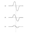
FE生成部9から出力されるFE信号は、光ビーム2の焦点が光ディスク情報記録面27よりも遠い場合には+側に出力し、近い場合には−側に出力する。
Further, the conventional optical disc apparatus has other problems described below.
FIG. 2 is an explanatory diagram for explaining another problem of the conventional optical disk apparatus.
The FE signal output from the FE generator 9 is output to the + side when the focal point of the
即ち、フォーカス制御部10は、光ビーム2の焦点を光ディスク情報記録面27に置くために、FE信号が点S0で示される値を維持するようにフォーカス制御信号を出力する。つまり、フォーカス制御部10は、点S0を基準にFE信号が+側に出力されているときには、焦点が光ディスク情報記録面27よりも遠いと判別して、焦点を光ディスク情報記録面27に近づけるフォーカス制御信号を出力し、FE信号が−側に出力されているときには、焦点が光ディスク情報記録面27に近すぎると判別して、焦点を光ディスク情報記録面27から遠ざけるフォーカス制御信号を出力する。
That is, the
ここで、フォーカスオフセット調整部29からオフセット信号が出力されると、FE信号が点S1で示される値を維持するように、焦点位置の制御が行われることとなる。
しかし、このようにオフセット信号が出力されると、FE信号の+側の制御範囲は、オフセット信号が出力されていないときの制御範囲と比べて狭くなり、検索中のトラバースメカニズムの振動によって焦点の位置が遠ざかる方向にすれていきFE信号のピークを越えてしまうと、焦点位置の制御がはずれてしまうという問題がある。また、光ビームスポットがトラックを横断するときに発生する溝横断信号の混入によっても焦点位置の制御が外れやすくなるという問題がある。
Here, when the offset signal is output from the focus
However, when the offset signal is output in this way, the control range on the + side of the FE signal becomes narrower than the control range when the offset signal is not output, and the focus of the FE signal is reduced by the vibration of the traverse mechanism being searched. If the position moves away from the peak of the FE signal, there is a problem that control of the focal position is lost. In addition, there is a problem that the control of the focal position is easily lost due to the inclusion of a groove crossing signal generated when the light beam spot crosses the track.
さらに、FE信号の+側及び−側を含めた制御範囲が狭い場合には、印加できるオフセット量が制限されるので、オフセット信号を印加しても光ビームスポットを十分に大きくすることができず、再生光劣化を防止することができないという問題がある。 Further, when the control range including the + side and the − side of the FE signal is narrow, the amount of offset that can be applied is limited, so that the light beam spot cannot be made sufficiently large even when the offset signal is applied. There is a problem that the reproduction light deterioration cannot be prevented.
そこで、本発明は、かかる問題点に鑑み、再生光劣化の防止効果を高めた光ディスク装置を提供することを目的とする。 Accordingly, an object of the present invention is to provide an optical disc apparatus with an improved effect of preventing reproduction light deterioration in view of such problems.
上記目的を達成するために、本発明に係る光ディスク装置は、光ディスクに光ビームを照射することにより前記光ディスクに記録された情報を読み出す光ディスク装置であって、前記光ディスクを回転させる回転手段と、前記光ディスク上の光ビームに照射されるスポットを、前記光ディスクに対して半径方向に移動させる移動手段と、前記スポットの線速度を検出する線速度検出手段と、前記光ディスクに記録された情報が読み出されるときには、前記光ディスク上の任意の半径位置において、前記線速度検出手段により検出された線速度が略一定となるように前記回転手段を制御する回転制御手段と、前記移動手段により前記スポットが移動されるときに、前記線速度検出手段によって検出された線速度が許容線速度以下になるのを防ぐように、前記回転手段及び前記移動手段の少なくとも一方を制御する移動時制御手段とを備えることを特徴とする。 In order to achieve the above object, an optical disc apparatus according to the present invention is an optical disc apparatus that reads information recorded on the optical disc by irradiating the optical disc with a light beam, the rotating means for rotating the optical disc, Moving means for moving the spot irradiated to the light beam on the optical disc in the radial direction with respect to the optical disc, linear velocity detecting means for detecting the linear velocity of the spot, and information recorded on the optical disc are read out Sometimes, the spot is moved by the rotation control means for controlling the rotation means so that the linear velocity detected by the linear velocity detection means becomes substantially constant at an arbitrary radial position on the optical disc, and the moving means. Prevents the linear velocity detected by the linear velocity detecting means from being below the allowable linear velocity. Sea urchin, characterized in that it comprises a moving time control means for controlling at least one of said rotating means and said moving means.
これにより、光ビームのスポットが光ディスクの半径方向に移動するときには、そのスポットの線速度が許容線速度以下にならないように制御されるため、その光ディスク上の前記スポットでの温度上昇を抑えて再生光劣化の発生を防ぐことができる。また、従来例のように光ビームの焦点を調整することで再生光劣化の発生を防止するものではないため、振動が生じても再生光劣化の発生を確実に防止することができる。 As a result, when the spot of the light beam moves in the radial direction of the optical disk, the spot is controlled so that the linear velocity of the spot does not fall below the allowable linear velocity. Occurrence of light degradation can be prevented. Further, unlike the conventional example, the occurrence of reproduction light deterioration is not prevented by adjusting the focal point of the light beam, so that the reproduction light deterioration can be reliably prevented even if vibration occurs.
また、前記移動時制御手段は、前記スポットを前記光ディスクに対して半径方向に沿って移動させるときには、前記移動に対応した半径位置と移動時間との関係を示す位置プロフィールを作成して、前記位置プロフィールに沿って前記スポットが移動するように前記移動手段を制御するとともに、前記線速度検出手段により検出された線速度が許容線速度に近づくと、前記線速度が低下しないように前記位置プロフィールを改変し、前記改変された位置プロフィールに沿って前記スポットが移動するように前記移動手段を制御することを特徴としても良い。例えば、前記移動手段が前記スポットを前記光ディスクの外周から内周に向かって移動させているときには、前記回転制御手段は前記回転手段に光ディスクの回転速度を増加させ、前記移動時制御手段は、前記移動中、前記線速度検出手段により検出された線速度が許容線速度に近づくと、前記移動手段による前記スポットの移動速度が低下するように前記位置プロフィールを改変する。 Further, when the movement control means moves the spot along the radial direction with respect to the optical disc, it creates a position profile indicating a relationship between a radial position corresponding to the movement and a movement time, and The moving means is controlled so that the spot moves along the profile, and when the linear velocity detected by the linear velocity detecting means approaches an allowable linear velocity, the position profile is controlled so that the linear velocity does not decrease. The moving means may be controlled so that the spot moves along the modified position profile. For example, when the moving means is moving the spot from the outer periphery to the inner periphery of the optical disk, the rotation control means causes the rotating means to increase the rotation speed of the optical disk, and the moving control means When the linear velocity detected by the linear velocity detecting means approaches the allowable linear velocity during the movement, the position profile is modified so that the moving speed of the spot by the moving means decreases.
このように、位置プロフィールが改変されることにより、例えば、前記回転手段による光ディスクの回転速度の増加率が悪くても、前記移動手段による前記スポットの移動速度が低下されるので、前記スポットの線速度が許容線速度以下にならずに再生光劣化の発生を防ぐことができる。 In this way, by changing the position profile, for example, even if the rate of increase in the rotation speed of the optical disk by the rotating means is poor, the moving speed of the spot by the moving means is reduced. It is possible to prevent the reproduction light from deteriorating without the speed being lower than the allowable linear speed.
ここで、前記光ディスク装置は、さらに、前記光ビームの照射対象となる光ディスクの種別を判定する種別判定手段を備え、前記移動時制御手段は、前記種別判定手段によって判定された光ディスクの種別に応じて前記許容線速度を変更することを特徴としても良い。 Here, the optical disc apparatus further includes a type determining unit that determines a type of the optical disc to be irradiated with the light beam, and the moving time control unit is responsive to the type of the optical disc determined by the type determining unit. The allowable linear velocity may be changed.
これにより、光ディスクの種別に応じて許容線速度が変更されるため、特定種類の光ディスクに限定されることなく、複数種の光ディスクに対して再生光劣化の発生を確実に防止することができる。 Thereby, since the allowable linear velocity is changed according to the type of the optical disc, it is possible to reliably prevent the deterioration of the reproduction light with respect to a plurality of types of optical discs without being limited to the specific type of optical disc.
また、前記移動時制御手段は、前記回転手段による光ディスクの回転速度を調整することを特徴としても良い。例えば、前記回転手段は、前記回転制御部から出力される駆動信号を取得して、前記駆動信号に応じて光ディスクの回転速度を変化させ、前記移動時制御手段は、前記線速度検出手段により検出された線速度が許容線速度に近づくと、前記線速度が低下しないように、前記駆動信号を増幅する。 Further, the moving time control means may adjust the rotation speed of the optical disk by the rotation means. For example, the rotation unit obtains a drive signal output from the rotation control unit, changes the rotation speed of the optical disc in accordance with the drive signal, and the movement control unit is detected by the linear velocity detection unit. When the linear velocity thus made approaches the allowable linear velocity, the drive signal is amplified so that the linear velocity does not decrease.
このように、駆動信号が増幅されることで、例えば、減速している回転速度の減速率が小さくなったり、又は加速している回転速度の増加率が大きくなったりするので、前記スポットの線速度が許容線速度以下にならずに再生光劣化の発生を防ぐことができる。 In this way, by amplifying the drive signal, for example, the deceleration rate of the rotating speed being decelerated is reduced, or the increasing rate of the accelerating rotational speed is increased. It is possible to prevent the reproduction light from deteriorating without the speed being lower than the allowable linear speed.
さらに、本発明は、光ディスクに光ビームを照射する照射方法として実現したり、その照射方法をコンピュータに実行させるプログラムや、そのプログラムを格納する記憶媒体として実現することもできる。 Furthermore, the present invention can be realized as an irradiation method for irradiating an optical disk with a light beam, a program for causing a computer to execute the irradiation method, and a storage medium for storing the program.
(実施の形態1)
以下、本発明の第1の実施の形態における光ディスク装置について、図面を参照しながら説明する。
(Embodiment 1)
Hereinafter, an optical disk device according to a first embodiment of the present invention will be described with reference to the drawings.
図3は、本発明の第1の実施の形態における光ディスク装置の構成を示す構成図である。
この光ディスク装置は、光ディスクに対する光ビームスポットの半径方向の移動速度を制御することにより再生光劣化の防止効果を高めたものであって、光ヘッド108と、トラバース111と、トラバース制御部113と、位置プロフィール作成部122と、FE生成部109と、フォーカス制御部110と、検索制御部121と、回転指令部120と、ディスクモータ114と、回転速度検出部115と、ディスクモータ制御部116とを備えるとともに、さらに、半径位置検出部112と、線速度演算部117と、位置プロフィール調整部118とを備えている。また、このような光ディスク装置では、光ディスク1から情報を読み出すときには、光ディスク1上の任意の半径位置において光ビームスポットの線速度が一定となるようにトラバース111及びディスクモータ114が制御される。
FIG. 3 is a block diagram showing the configuration of the optical disc apparatus according to the first embodiment of the present invention.
This optical disk device has an effect of preventing deterioration of reproduction light by controlling the moving speed of the light beam spot in the radial direction with respect to the optical disk, and includes an
光ヘッド108は、従来例の光ヘッド8と同様、光ディスク1に対して収束された光ビーム2を照射するものであって、光ビーム2を出力する光ビーム照射部103と、その光ビーム2を透過及び反射するビームスプリッタ104と、光ビーム2を収束する収束レンズ105と、収束レンズ105を駆動することにより、その収束レンズ105を透過して収束される光ビーム2の焦点を移動させるフォーカスアクチュエータ107と、光ビーム2を検出して検出結果に応じた光検出信号を出力するフォトディテクタ106とを備えている。
Similar to the
光ビーム照射部103から出力された光ビーム2は、ビームスプリッタ104を通過し、収束レンズ105により光ディスク1上へ収束される。また、光ディスク1で反射された光ビーム2は、収束レンズ105を通過し、ビームスプリッタ104によりフォトディテクタ106へ照射される。
The
FE生成部109は、フォトディテクタ106からの光検出信号に基づいて、収束レンズ105により収束された光ビーム2の焦点と、光ディスク1の光ディスク情報記録面27との間における、光ディスク情報記録面27に対して法線方向の位置ずれを示すFE信号を生成し、そのFE信号をフォーカス制御部110に対して出力する。
Based on the light detection signal from the
フォーカス制御部110は、FE生成部109から出力されたFE信号に基づいて、光ビーム2の焦点を光ディスク情報記録面27上に正しく合わせるように、フォーカスアクチュエータ107をフィードバック制御するためのフォーカス制御信号を出力する。
The
トラバース111は、トラバース制御部113からのトラバース駆動信号に基づいて光ヘッド108を光ディスク1の半径方向に移動させることで、光ヘッド108から出力される光ビーム2の光ディスク1上の照射部位(光ビームスポット)の位置を変化させる。また、本実施の形態におけるトラバース111は、光ディスク1の最内周の位置を基準に、光ビームスポットを任意の半径位置まで移動させたときの結果を示す移動信号を出力する。
The
ディスクモータ114は、ディスクモータ制御部116からのモータ駆動信号に基づいて光ディスク1を回転させるとともに、その回転周波数を示す周波数信号(FG信号)を生成してこれを回転速度検出部115に出力する。
The
検索制御部121は、光ディスク1上の目標とする半径位置(目標半径位置)に光ビームスポットを移動させる検索動作を行うために、その目標半径位置を示す検索目標半径位置情報を位置プロフィール作成部122および回転指令部120に出力する。
In order to perform a search operation for moving the light beam spot to a target radial position (target radial position) on the
また、本実施の形態における検索制御部121は、光ビームスポットを半径方向に沿って目標半径位置に移動させるときの向き(検索方向)を示す検索半径方向情報を位置プロフィール調整部118に出力する。
In addition, the
回転指令部120は、検索制御部121からの検索目標半径位置情報に基づいて、光ビームスポットの線速度が一定となるような光ディスク1の目標回転速度を導出し、その目標回転速度を示す目標回転速度情報を出力する。つまり、回転指令部120は、光ディスク1からデータが読み出されるとき(光ビームスポットが半径方向に移動していないとき)には、光ディスク1の任意の半径位置において、その線速度が一定となるような目標回転速度を導出する。また、このように一定となる線速度を以下、標準線速度という。
The
回転速度検出部115は、ディスクモータ114の周波数信号に基づいて、光ディスク1の回転速度を検出して、その回転速度を示す回転速度情報を出力する。
ディスクモータ制御部116は、回転速度検出部115からの回転速度情報と、回転指令部20からの目標回転速度情報とに基づいて、光ディスク1の回転速度が目標回転速度に整定するようにディスクモータ14を駆動させるモータ駆動信号をディスクモータ114に出力する。
The
The disk
半径位置検出部112は、トラバース111から出力される移動信号を取得して、光ビームスポットの光ディスク1上の半径位置を検出し、その半径位置を示す半径位置情報を線速度演算部117に出力する。
The radial
線速度演算部117は、半径位置検出部112からの半径位置情報と、回転速度検出部115からの回転速度情報とに基づいて、光ビームスポットの光ディスク1上での線速度を算出する。
The
位置プロフィール調整部118は、検索制御部121からの検索半径方向情報と線速度演算部117からの線速度情報とに基づいて、検索の実行中に線速度が所定の値(許容線速度)以下にならないように、位置プロフィール作成部122へ位置プロフィールを調整するように指示する調整指示信号を出力する。
Based on the search radial direction information from the
位置プロフィール作成部122は、検索制御部121からの検索目標半径位置情報と、位置プロフィール調整部118からの調整指示信号とに基づいて、光ビームスポットの位置プロフィールを作成する。
The position
即ち、位置プロフィール作成部122は、まず、検索制御部121からの検索目標半径位置情報に基づいて、基本となる位置プロフィールを作成し、位置プロフィール調整部118からの調整指示信号に基づいて、その基本となる位置プロフィールに対する調整を行う。
That is, the position
図4は、光ディスク1の内周から外周に向かって検索が行われるときにおける上記基本の位置プロフィールの一例を示すプロフィール表示図である。
位置プロフィール作成部122は、検索制御部121からの検索目標半径位置情報に基づいて、光ビームスポットの目標半径位置がD2であって、半径位置D1から外周に向かって光ビームスポットを移動させる必要があると判別すると、半径位置D1から一定の加速度で光ビームスポットの移動を開始させ、途中で移動速度を一定に保ち、半径位置D2に近づくと移動速度を一定の加速度で低下させるような位置プロフィールを作成する。
FIG. 4 is a profile display diagram showing an example of the basic position profile when a search is performed from the inner periphery to the outer periphery of the
Based on the search target radius position information from the
図5は、光ディスク1の外周から内周に向かって検索が行われるときにおける上記基本の位置プロフィールの一例を示すプロフィール表示図である。
位置プロフィール作成部122は、検索制御部121からの検索目標半径位置情報に基づいて、光ビームスポットの目標半径位置がD3であって、半径位置D4から内周に向かって光ビームスポットを移動させる必要があると判別すると、半径位置D4から一定の加速度で光ビームスポットの移動を開始させ、途中で移動速度を一定に保ち、半径位置D3に近づくと移動速度を一定の加速度で低下させるような位置プロフィールを作成する。
FIG. 5 is a profile display diagram showing an example of the basic position profile when a search is performed from the outer periphery to the inner periphery of the
Based on the search target radius position information from the
このように作成された基本となる位置プロフィールに対して、位置プロフィール作成部122は、位置プロフィール調整部118からの調整指示信号に基づく調整を行い、その調整指示信号に示される内容が反映された位置プロフィールを作成する。
For the basic position profile created in this way, the position
また詳細には、位置プロフィール作成部122は、光ビームスポットの半径方向の移動速度と移動距離との関係(以下、速度プロフィールという)から、上述のような位置プロフィールを作成している。
More specifically, the position
図6は、速度プロフィールと位置プロフィールとの関係を説明するための説明図であって、図6の(a)は速度プロフィールを示し、図6の(b)は位置プロフィールを示す。
この図6の(a)に示すように、位置プロフィール作成部122は、光ビームスポットの移動開始から、移動速度が徐々に増加して、途中で移動速度が一定となり、その後、移動速度が徐々に減少するような速度プロフィールを作成する。その結果、図6の(b)に示すような位置プロフィールが作成されることとなる。
6A and 6B are explanatory diagrams for explaining the relationship between the velocity profile and the position profile. FIG. 6A shows the velocity profile, and FIG. 6B shows the position profile.
As shown in FIG. 6A, the position
例えば、位置プロフィール作成部122は、検索制御部121から検索目標半径位置情報を取得して、その検索目標半径位置情報から距離L5だけ光ビームスポットを移動させる必要があると判別すると、図6の(a)の実線に示すように、光ビームスポットの移動開始から距離L1までの移動区間では、移動速度が一定の加速度で増加して、距離L1から距離L3までの移動区間では、移動速度が一定(速度V1)となり、距離L3から距離L5までの移動区間では、移動速度が一定の加速度で減少するような速度プロフィールを作成する。その結果、図6の(b)の実線に示すように、移動開始時の時刻0から時刻t5までの時間にかけて、光ビームスポットが半径位置d1から距離L5に対応した目標半径位置d6に移動するような位置プロフィールが作成される。
For example, when the position
また、位置プロフィール作成部122は、検索制御部121から検索目標半径位置情報を取得して、その検索目標半径位置情報から距離L4だけ光ビームスポットを移動させる必要があると判別すると、図6の(a)の点線に示すように、光ビームスポットの移動開始から距離L1までの移動区間では、移動速度が一定の加速度で増加して、距離L1から距離L2までの移動区間では、移動速度が一定(速度V1)となり、距離L2から距離L4までの移動区間では、移動速度が一定の加速度で減少するような速度プロフィールを作成する。その結果、図6の(b)の点線に示すように、移動開始時の時刻0から時刻t4までの時間にかけて、光ビームスポットが半径位置d1から距離L4に対応した目標半径位置d5に移動するような位置プロフィールが作成される。
When the position
そして、トラバース制御部113は、上述のように位置プロフィール作成部122によって作成された位置プロフィールに沿って光ビームスポットが移動するようにトラバース111を駆動させるトラバース駆動信号を出力する。
Then, the
ここで、本実施の形態における位置プロフィールの調整について、さらに詳しく説明する。
図7は、光ディスク1の内周か外周に向かって検索が行われるときにおける、調整後の位置プロフィール及びそれに基づく光ビームスポットの線速度を示す特性図である。
Here, the adjustment of the position profile in the present embodiment will be described in more detail.
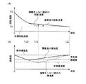
FIG. 7 is a characteristic diagram showing the adjusted position profile and the linear velocity of the light beam spot based on the position profile when searching toward the inner or outer periphery of the
例えば、光ビームスポットを半径位置D5から外周に向かって目標半径位置D6に移動して検索を行うときには、検索制御部121及び回転指令部120並びにディスクモータ制御部116は、その移動開始時(検索開始時)の時刻0から時刻T3までの間、ディスクモータ114によって回転される光ディスク1の回転速度を低下させ、その時刻T3経過時には、その回転速度を目標半径位置D6に応じた回転速度に設定する。
For example, when a search is performed by moving the light beam spot from the radial position D5 to the target radial position D6 toward the outer periphery, the
ここで仮に、トラバース制御部113及びトラバース111が、調整後の位置プロフィールに沿って光ビームスポットを移動させずに、図7の(a)の点線に示す基本となる位置プロフィールに沿って、光ビームスポットを検索開始時から時刻T4まで移動させると、図7の(b)の点線に示すように、光ディスク1上の光ビームスポットの線速度は許容線速度以下になる。つまり、この場合には、従来例のように再生光劣化を発生させてしまうことがある。
Here, it is assumed that the
しかしながら本実施の形態では、線速度演算部117によって算出された線速度に対する位置プロフィール調整部118からの調整指示信号に基づいて、位置プロフィール作成部122が位置プロフィールを図7の(a)の実線に示すように調整し、その調整された位置プロフィールに沿って光ビームスポットが半径方向に移動されるため、上述の線速度は、図7の(b)の実線に示すように許容線速度を越えるように維持されて、再生光劣化の防止を図ることができる。
However, in the present embodiment, based on the adjustment instruction signal from the position
つまり、位置プロフィール調整部118は、線速度が準許容線速度以下になると、その線速度が許容線速度に近づいていることを把握する。そして位置プロフィール調整部118は、線速度が準許容線速度以下になった時刻T1以降の位置プロフィールを調整し、光ビームスポットの半径方向の移動速度が速くなるように、位置プロフィール作成部122に指示する。その結果、光ビームスポットの線速度は、光ディスク1の回転速度が低下しても、許容線速度を越えるように維持されて、再生光劣化を防止することができる。
That is, when the linear velocity becomes equal to or less than the semi-allowable linear velocity, the position
なお、線速度は、図7の(b)に示すように、時刻T1から時刻T2までの間、光ビームスポットの半径方向の移動速度が速くなるため線速度は上昇し、時刻T2を経過すると、光ビームスポットの半径方向への移動が停止されるため、ディスモータ114による光ディスク1の回転速度の低下に応じて線速度は減少する。そして、光ディスク1の回転速度が一定となる時刻T3を経過すると、それ以降、線速度は標準線速度に保たれる。
Note that, as shown in FIG. 7B, the linear velocity increases as the moving speed of the light beam spot in the radial direction increases from time T1 to time T2, as shown in FIG. 7B. Since the movement of the light beam spot in the radial direction is stopped, the linear velocity decreases as the rotational speed of the
図8は、光ディスク1の外周から内周に向かって検索が行われるときにおける、調整後の位置プロフィール及びそれに基づく光ビームスポットの線速度を示す特性図である。
例えば、光ビームスポットを半径位置D8から内周に向かって目標半径位置D7に移動して検索を行うときには、検索制御部121及び回転指令部120並びにディスクモータ制御部116は、その移動開始時(検索開始時)の時刻0から時刻T7までの間、ディスクモータ14によって回転される光ディスク1の回転速度を大きくさせ、その時間T7経過時には、その回転速度を目標半径位置D7に応じた回転速度(目標回転速度)に設定する。
FIG. 8 is a characteristic diagram showing the adjusted position profile and the linear velocity of the light beam spot based on the position profile when searching from the outer periphery to the inner periphery of the
For example, when searching by moving the light beam spot from the radial position D8 toward the inner radius toward the target radial position D7, the
ここで仮に、トラバース制御部113及びトラバース111が、調整後の位置プロフィールに沿って光ビームスポットを移動させずに、図8の(a)の点線に示す基本となる位置プロフィールに沿って、光ビームスポットを半径方向に時刻T6まで移動させると、その時刻T6までにディスクモータ114は光ディスク1の回転速度を目標半径位置D7に応じた回転速度に上昇することができず時刻T7までかかるため、図8の(b)の点線に示すように、光ディスク1上の光ビームスポットの線速度は許容線速度以下になる。つまり、この場合には、従来例のように再生光劣化を発生させてしまうことがある。
Here, it is assumed that the
しかしながら本実施の形態では、線速度演算部117によって算出された線速度に対する位置プロフィール調整部118からの調整指示信号に基づいて、位置プロフィール作成部122が位置プロフィールを図8の(a)の実線に示すように調整し、その調整された位置プロフィールに沿って光ビームスポットが半径方向に移動されるため、上述の線速度は、図8の(b)の実線に示すように許容線速度を越えるように維持されて、再生光劣化の防止を図ることができる。
However, in the present embodiment, based on the adjustment instruction signal from the position
つまり、位置プロフィール調整部118は、線速度が準許容線速度以下になると、その線速度が許容線速度に近づいていることを把握する。そして位置プロフィール調整部118は、線速度が準許容線速度以下になった時刻T5以降の位置プロフィールを調整し、光ビームスポットの半径方向の移動速度が遅くなるように、位置プロフィール作成部122に指示する。その結果、光ビームスポットの線速度は、光ディスク1の回転速度の上昇が十分でなくても、許容線速度を越えるように維持されて、再生光劣化を防止することができる。
That is, when the linear velocity becomes equal to or less than the semi-allowable linear velocity, the position
このような本実施の形態における光ディスク装置の特徴的な動作について、図9を参照して説明する。
図9は、本実施の形態における光ディスク装置の動作を示すフロー図である。
The characteristic operation of the optical disc apparatus according to the present embodiment will be described with reference to FIG.
FIG. 9 is a flowchart showing the operation of the optical disk apparatus according to the present embodiment.
まず、光ディスク装置は、線速度が準許容線速度以下であるか否かを判別する(ステップS100)。そして、線速度が準許容線速度以下であると判別したときには(ステップS100のY)、光ディスク装置は、基本的な位置プロフィールを作成して、さらにそれに調整を加えた位置プロフィールを作成する(ステップS102)。 First, the optical disc apparatus determines whether or not the linear velocity is equal to or lower than the semi-allowable linear velocity (step S100). When it is determined that the linear velocity is equal to or less than the quasi-allowable linear velocity (Y in step S100), the optical disc apparatus creates a basic position profile and creates a position profile with further adjustments (step). S102).
一方、線速度が準許容線速度以下ではないと判別すると(ステップS100のN)、光ディスク装置は、基本的な位置プロフィールを作成する(ステップS104)。
そして、光ディスク装置は、トラバース111の駆動により光ヘッド108を移動して、上述のように作成された位置プロフィールに沿って光ビームスポットを光ディスク1の半径方向に移動させる(ステップS106)。
On the other hand, if it is determined that the linear velocity is not less than or equal to the quasi-allowable linear velocity (N in step S100), the optical disc apparatus creates a basic position profile (step S104).
Then, the optical disc apparatus moves the
このように、本実施の形態では、従来例のように光ビーム2の焦点調整によって再生光劣化を防止しようとするものではなく、位置プロフィールを調整することによって再生光劣化を防止するため、検索中のトラバースメカニズムに振動が生じても再生光劣化を防ぐことができるとともに、焦点位置の制御の困難性を回避することができ、さらに、FE信号の出力範囲に制限されることなく十分に再生光劣化を防止することができる。また、本実施の形態では、外周から内周に向かって検索するときに、線速度を標準線速度に保つために行われるディスクモータ114の加速が遅くても、光ビームスポットの検索方向の移動速度が調整されるため、再生光劣化を生ずることなく検索することができる。
As described above, in the present embodiment, the reproduction light deterioration is not prevented by adjusting the focus of the
なお、本実施の形態では、位置プロフィール調整部118の指示に基づいて位置プロフィール作成部122が位置プロフィールを調整し、その位置プロフィールに沿って光ビームスポットが移動するようにトラバース制御部113がトラバース111を駆動させたが、位置プロフィールを調整することなく、トラバース制御部113がトラバースゲインを調整してもよい。
In the present embodiment, the position
つまり、トラバース制御部113は、線速度演算部117により算出された線速度を取得し、その線速度が許容線速度以下とならないように、トラバース111に出力するトラバース駆動信号に対して増幅又は減少するなどの信号処理(トラバースゲインの調整)を施す。トラバース111は、そのトラバース駆動信号に基づいて光ヘッド108、即ち光ビームスポットの検索方向(光ディスク1の半径方向の内向き又は外向き)の移動速度を変化させる。
That is, the
例えば、トラバース制御部113は、外周から内周に向かって検索が行われる場合には、トラバースゲインを低く調整して、光ビームスポットの検索目標半径位置への移動速度を減速させ、内周から外周方向に向かって検索が行われる場合には、トラバースゲインを高く調整して、光ビームスポットの検索目標半径位置への移動速度を加速させる。
For example, when the search is performed from the outer periphery toward the inner periphery, the
このようにトラバースゲインを調整することは、位置プロフィール及び速度プロフィールを調整していることと同等の効果を奏する。
図10は、トラバースゲインと位置プロフィール及び速度プロフィールとの関係を説明するための説明図であって、図10の(a)は速度プロフィールを示し、図10の(b)は位置プロフィールを示す。
Adjusting the traverse gain in this way has the same effect as adjusting the position profile and velocity profile.
10A and 10B are explanatory diagrams for explaining the relationship between the traverse gain, the position profile, and the velocity profile. FIG. 10A shows the velocity profile, and FIG. 10B shows the position profile.
例えば、トラバースゲインを増加するという処理によって生じる移動速度の変化は、速度プロフィールを、図10の(a)の実線から点線に示すように調整するという処理、即ち、位置プロフィールを、図10の(b)の実線から点線に示すように調整するという処理によって生じる移動速度の変化と等しい。 For example, the change in the moving speed caused by the process of increasing the traverse gain is a process of adjusting the speed profile as shown by the dotted line from the solid line in FIG. It is equal to the change in the moving speed caused by the process of adjusting from the solid line to the dotted line in b).
また、トラバース制御部113がトラバース駆動信号にオフセットを印加してもよい。オフセットが印加されることにより、トラバース111がトラバース駆動信号として取得する信号の値が大きく又は小さくなり、これにより光ビームスポットの検索方向への移動速度が調整される。例えば、外周から内周に検索が行われる場合は、負のオフセットを印加することで光ビームスポットの検索目標半径位置への移動速度を減速し、内周から外周方向に検索が行われる場合は、正のオフセットを印加することで光ビームスポットの検索目標半径位置への移動速度を加速する。その結果、光ディスク1に対する光ビームスポットの線速度を許容線速度以上に維持することができる。
(変形例)
次に、上記本実施の形態における光ディスク装置の変形例について説明する。
Further, the
(Modification)
Next, a modification of the optical disk device in the present embodiment will be described.
図11は、変形例に係る光ディスク装置の構成を示す構成図である。
この変形例に係る光ディスク装置は、光ディスク1の種類を判別してその種類に応じて許容線速度を変更するとともに、位置プロフィールを調整するものであって、光ディスク1の種別を判別する種別判定部201を備えている。
FIG. 11 is a configuration diagram illustrating a configuration of an optical disc device according to a modification.
The optical disc apparatus according to this modified example discriminates the type of the
光ディスク1には幾つかの種類があり、例えばCD(Compact Disc)や、DVD(Digital Versatile disc)、BD(Blu-ray Disc)などがある。
図12は、上述のCD及びDVD並びにBDの仕様を説明するための説明図である。
There are several types of the
FIG. 12 is an explanatory diagram for explaining the specifications of the above-described CD, DVD, and BD.
BDでは、照射される光ビーム2の最適な波長(レーザ波長)は405[nm]であり、再生に必要な光ビーム2の出力(再生パワー)は0.3[mW]であり、標準線速度は4.917[m/s]である。
In BD, the optimum wavelength (laser wavelength) of the irradiated
DVDでは、レーザ波長は650[nm]であり、再生パワーは1[mW]であり、標準線速度は8.16〜8.49[m/s]である。
またCDでは、レーザ波長は780[nm]であり、再生パワーは0.7[mW]であり、標準線速度は1.3[m/s]である。
In DVD, the laser wavelength is 650 [nm], the reproduction power is 1 [mW], and the standard linear velocity is 8.16 to 8.49 [m / s].
In CD, the laser wavelength is 780 [nm], the reproduction power is 0.7 [mW], and the standard linear velocity is 1.3 [m / s].
ここで、本実施の形態における光ビーム照射部103は、光ディスク装置に装填される上述のような光ディスク1の種類に応じて、照射する光ビーム2の波長及び出力を変化させる。
Here, the light
フォーカス制御部110は、光ビーム照射部103から所定の波長で光ビーム2が照射されている状態で、フォーカスアクチュエータ107を制御して収束レンズ105を移動させる。そして、FE生成部109’は、その収束レンズ105の移動結果に応じたFE信号を出力する。
The
種別判定部201は、FE生成部109’から出力されるFE信号を取得して、そのFE信号に基づいて、光ディスク装置に装填された光ディスク1の種類を判別する。
図13は、収束レンズ105を移動させたときに出力されるFE信号の波形を示す波形図である。
The
FIG. 13 is a waveform diagram showing the waveform of the FE signal output when the converging
上述のようにBD及びDVD並びにCDのそれぞれに最適なレーザ波長が異なっているため、例えば、光ビーム照射部103から波長405[nm]の光ビーム2が照射されている場合、光ディスク装置にBDが装填されていれば、FE生成部109’は、図13の(a)に示すように広い振幅のFE信号を出力し、DVDが装填されていれば、図13の(b)に示すように上記振幅よりも狭い振幅のFE信号を出力し、CDが装填されていれば、図13の(c)に示すように振幅のさらに狭いFE信号を出力する。
As described above, since the optimum laser wavelength is different for each of BD, DVD, and CD, for example, when the
また、光ビーム照射部103から波長780[nm]の光ビーム2が照射されている場合、光ディスク装置にBDが装填されていれば、FE生成部109’は、図13の(c)に示すように狭い振幅のFE信号を出力し、DVDが装填されていれば、図13の(b)に示すように上記振幅よりも広い振幅のFE信号を出力し、CDが装填されていれば、図13の(a)に示すように振幅のさらに広いFE信号を出力する。
Further, when the
種別判定部201は、このようなFE信号の振幅の違いに基づいて、光ディスク装置に装填された光ディスク1の種類を判別し、その判別結果を示す種別情報を位置プロフィール調整部118’及び位置プロフィール作成部122’に出力する。
The
位置プロフィール調整部118’は、種別判定部201から種別情報を取得すると、その種別情報に基づいて、光ディスク装置に装填された光ディスク1に対応した標準線速度及び許容線速度を特定する。そして、位置プロフィール調整部118’は、線速度演算部117で算出された線速度が、その特定された許容線速度以下とならないように位置プロフィール作成部122’に対して指示する。
When the position
位置プロフィール作成部122’は、種別判定部201から種別情報を取得すると、その種別情報に基づいて、光ディスク装置に装填された光ディスク1に対応した基本的な位置プロフィールを作成する。また、位置プロフィール作成部122’は、位置プロフィール調整部118’からの指示に基づいて、その基本的な位置プロフィールに対する調整を行う。
When the position
図14は、光ディスク1の外周から内周に向かって検索が行われるときにおける基本的な位置プロフィール及びそれに基づく光ビームスポットの線速度を示す特性図である。
位置プロフィール作成部122’は、図14の(a)に示すように、半径位置D10から内周にある目標半径位置D9に向かって検索が行われるときに、光ディスク1の種類がBDであることを示す種別情報を種別判定部201から取得すると、位置プロフィールPf1を基本的な位置プロフィールとして作成し、光ディスク1の種類がDVDであることを示す種別情報を取得すると、位置プロフィールPf1よりも傾斜の大きな位置プロフィールPf2を基本的な位置プロフィールとして作成し、光ディスク1の種類がCDであることを示す種別情報を取得すると、位置プロフィールPf2よりもさらに傾斜の大きな位置プロフィールPf3を基本的な位置プロフィールとして作成する。
FIG. 14 is a characteristic diagram showing a basic position profile and a linear velocity of a light beam spot based on the search when a search is performed from the outer periphery to the inner periphery of the
As shown in FIG. 14A, the position
つまり、位置プロフィール作成部122’は、光ディスク1の種類がBDであるときには、時刻T12に光ビームスポットが目標半径位置D9に到達するような位置プロフィールPf1を作成し、光ディスク1の種類がDVDであるときには、時刻T12を経過する前の時刻T11に光ビームスポットが目標半径位置D9に到達するような位置プロフィールPf2を作成し、光ディスクの種類がCDであるときには、時刻T11を経過する前の時刻T10に光ビームスポットが目標半径位置D9に到達するような位置プロフィールPf3を作成する。
That is, when the type of the
ここで、光ディスク装置に装填された光ディスク1の種類がBDであって、位置プロフィールPf1に沿って光ビームスポットが移動するときには、線速度演算部117で算出される線速度V1は、検索開始時の標準線速度Vs1から次第に減少し、光ビームスポットが目標半径位置D9に到達する時刻T12で最小となり、その後、線速度V1は光ディスク1の回転速度の増加に応じて上昇し、時刻T13に再び標準線速度Vs1となる。
Here, when the type of the
そして、位置プロフィール調整部118’は、上述のような線速度V1を示す線速度情報を取得し、さらに、光ディスク1の種類がBDであることを示す種別情報を取得すると、線速度V1がBDに応じた許容線速度Vp1以下にならないように、位置プロフィール作成部122’へ位置プロフィールPf1を調整するように指示する。
Then, when the position
また、光ディスク装置に装填された光ディスク1の種類がDVDであって、位置プロフィールPf2に沿って光ビームスポットが移動するときには、線速度演算部117で算出される線速度V2は、検索開始時の標準線速度Vs2から次第に減少し、光ビームスポットが目標半径位置D9に到達する時刻T11で最小となり、その後、線速度V2は光ディスク1の回転速度の増加に応じて上昇し、時刻T13に再び標準線速度Vs2となる。
When the type of the
そして、位置プロフィール調整部118’は、上述のような線速度V2を示す線速度情報を取得し、さらに、光ディスク1の種類がDVDであることを示す種別情報を取得すると、線速度V2がDVDに応じた許容線速度Vp2以下にならないように、位置プロフィール作成部122’へ位置プロフィールPf2を調整するように指示する。
Then, the position
また、光ディスク装置に装填された光ディスク1の種類がCDであって、位置プロフィールPf3に沿って光ビームスポットが移動するときには、線速度演算部117で算出される線速度V3は、検索開始時の標準線速度Vs3から次第に減少し、光ビームスポットが目標半径位置D9に到達する時刻T10で最小となり、その後、線速度V3は光ディスク1の回転速度の増加に応じて上昇し、時刻T13に再び標準線速度Vs3となる。
When the type of the
そして、位置プロフィール調整部118’は、上述のような線速度V3を示す線速度情報を取得し、さらに、光ディスク1の種類がCDであることを示す種別情報を取得すると、線速度V3がCDに応じた許容線速度Vp3以下にならないように、位置プロフィール作成部122’へ位置プロフィールPf3を調整するように指示する。
Then, the position
図15は、BDに対して上述のように位置プロフィールが調整される様子を説明するための説明図である。
図15の(b)に示すように、位置プロフィール調整部118’は、線速度演算部117からの線速度情報から、線速度V1が時刻T0に準許容線速度Vp1’になると、線速度V1が許容線速度Vp1に近づいていることを把握し、光ビームスポットの半径方向の移動速度が速くなるように、つまり、図15の(a)に示すように、時刻T0以降の位置プロフィールPf1を位置プロフィールPf1’となるように指示する。その結果、位置プロフィール作成部122’は、位置プロフィールPf1を調整して位置プロフィールPf1’を作成する。
FIG. 15 is an explanatory diagram for explaining how the position profile is adjusted as described above with respect to the BD.
As shown in FIG. 15 (b), the position
図16は、CDに対して上述のように位置プロフィールが調整される様子を説明するための説明図である。
図16の(b)に示すように、位置プロフィール調整部118’は、線速度演算部117からの線速度情報から、線速度V3が時刻T0’に準許容線速度Vp3’になると、線速度V3が許容線速度Vp3に近づいていることを把握し、光ビームスポットの半径方向の移動速度が速くなるように、つまり、図16の(a)に示すように、時刻T0’以降の位置プロフィールPf3を位置プロフィールPf3’となるように指示する。その結果、位置プロフィール作成部122’は、位置プロフィールPf3を調整して位置プロフィールPf3’を作成する。
FIG. 16 is an explanatory diagram for explaining how the position profile is adjusted as described above for a CD.
As shown in FIG. 16 (b), the position
上述のように、本変形例にかかる光ディスク装置について、光ディスク1の外周から内周に向かって検索が行われる場合における動作を説明したが、光ディスク1の内周から外周に向かって検索が行われる場合にも、上述と同様、本変形例にかかる光ディスク装置は、光ディスクの種類に応じた基本的な位置プロフィールを作成し、その種類に応じた許容線速度及び準許容線速度に基づいてその位置プロフィールを調整する。
As described above, the operation in the case where the search is performed from the outer periphery to the inner periphery of the
このように本変形例に係る光ディスク装置は、光ディスク装置に装填された光ディスク1の種類に応じて位置プロフィールを調整するため、特定の種類の光ディスクに限ることなく再生光劣化の発生を確実に防止することができる。
As described above, since the optical disc apparatus according to this modification adjusts the position profile according to the type of the
なお、本変形例では、光ディスク装置に装填された光ディスク1の種類をFE信号に基づいて判別したが、他の判別方法により光ディスク1の種類を判別しても良い。
例えば、光ディスク情報記録面27の位置に応じて光ディスク1の種類を判別しても良い。
In this modification, the type of the
For example, the type of the
図17は、光ディスク情報記録面27の位置を示す光ディスク1の断面図である。
この図17の(a)に示すように、CDでは、光ディスク情報記録面27は、光ディスク1の収束レンズ105側の表面から厚さ1.2[mm]の位置にあり、図17の(b)に示すように、DVDでは、光ディスク情報記録面27は、光ディスク1の収束レンズ105側の表面から厚さ0.6[mm]の位置にある。また、図17の(c)に示すように、BDとDVDの複合ディスクでは、光ディスク情報記録面27は、光ディスク1の収束レンズ105側の表面から厚さ0.1[mm]と0.6[mm]の位置にあり、情報はそのコンテンツ(例えばビデオデータやテキストデータなど)に応じて異なる光ディスク情報記録面27に記録される。
FIG. 17 is a cross-sectional view of the
As shown in FIG. 17A, in the CD, the optical disc
即ち、光ディスク装置は、光ビーム2の焦点を光ディスク情報記録面27に合わせたときに、その焦点距離に基づいて、装填された光ディスク1がBD及びDVD並びにCDのいずれであるかを判別する。
That is, the optical disc apparatus determines whether the loaded
また、図12に示すように、光ディスク1の種類に応じて再生パワーが異なることから、その再生パワーに応じて光ディスク1の種類を判別しても良い。
例えば、光ディスク装置は、光ビーム2の出力を0.3[mW]及び0.7[mW]並びに1[mW]に切り替えて出力し、そのときの信号出力結果に基づいて、装填されている光ディスク1の種類を特定する。即ち、出力0.3[mW]で信号が読み取れたときには、光ディスク装置は、装填された光ディスク1の種類がBDと判別し、出力0.7[mW]で信号が読み取れたときには、光ディスク装置は、装填された光ディスク1の種類がCDと判別し、出力1[mW]で信号が読み取れたときには、光ディスク装置は、装填された光ディスク1の種類がDVDと判別する。
In addition, as shown in FIG. 12, since the reproduction power varies depending on the type of the
For example, the optical disc apparatus is loaded based on the signal output result at that time by switching the output of the
ここで、光ディスク装置は、光ディスク1に書かれた再生パワーや標準線速度を読み取ることにより、その光ディスク1の種類を判別しても良い。なお、このような再生パワーや標準線速度は、光ディスク1に記録される他の情報と異なり、再生光劣化が生じないように予め光ディスク1に書き込まれている。
Here, the optical disk apparatus may determine the type of the
また、光ディスク装置は、光ディスク1が所定のケースに収められた状態で光ディスク装置に装填されているか否かを判別し、その結果に応じて光ディスク1の種類を特定しても良い。即ち、CDはケースに収められることなく光ディスク装置に装填されるが、BDはケースに納められた状態で光ディスク装置に装填される。そこで、光ディスク装置は、そのケースの有無に応じて光ディスク1の種類を特定する。
Further, the optical disc apparatus may determine whether or not the
また、本実施の形態及び変形例では、光ビームスポットの半径位置とディスクモータ114の回転速度から光ディスク1に対する光ビームスポットの線速度を算出したが、さらに、光ビームスポットの検索方向とその移動速度も考慮して線速度を算出しても良い。
In this embodiment and the modification, the linear velocity of the light beam spot with respect to the
(実施の形態2)
以下、本発明の第2の実施の形態における光ディスク装置について、図面を参照しながら説明する。
(Embodiment 2)
Hereinafter, an optical disk device according to a second embodiment of the present invention will be described with reference to the drawings.
図18は、本発明の第2の実施の形態における光ディスク装置の構成を示す構成図である。
この光ディスク装置は、光ディスクの回転速度を制御することにより再生光劣化の防止効果を高めたものであって、実施の形態1と同様、光ヘッド108と、トラバース111と、トラバース制御部113と、FE生成部109と、フォーカス制御部110と、回転指令部120と、ディスクモータ114と、回転速度検出部115と、ディスクモータ制御部116と、半径位置検出部112と、線速度演算部117と、検索制御部121とを備えるとともに、さらに、位置プロフィール作成部122aと、ゲイン調整部123と、ゲイン増加部124とを備えている。
FIG. 18 is a block diagram showing the configuration of the optical disc apparatus according to the second embodiment of the present invention.
This optical disk apparatus has an improved effect of preventing deterioration of reproduction light by controlling the rotation speed of the optical disk. Like the first embodiment, the
ここで、本実施の形態における光ディスク装置が備える上述の構成要素のうち、実施の形態1と同一の機能及び構成を有する構成要素に対しては、実施の形態1の構成要素に付された符号と同一の符号を付して説明を省略する。 Here, among the above-described components included in the optical disc apparatus according to the present embodiment, components having the same functions and configurations as those of the first embodiment are denoted by the reference numerals given to the components of the first embodiment. The same reference numerals are used and the description thereof is omitted.
本実施の形態における位置プロフィール作成部122aは、検索制御部121からの検索目標半径位置情報に基づいて基本となる位置プロフィールを作成する。
ゲイン調整部123は、検索制御部121からの検索半径方向情報と、線速度演算部117からの線速度情報とに基づいて、検索の実行中に線速度が所定の値(許容線速度)以下にならないように、ゲイン増加部124に対する指示を行う。
The position
Based on the search radial direction information from the
ゲイン増加部124は、ゲイン調整部123からの指示に基づいて、ディスクモータ制御部116から出力されるモータ駆動信号を増幅し、その増幅されたモータ駆動信号をディスクモータ114に出力する。つまり、ゲイン増加部124は、ディスクモータ制御部116から出力されるモータ駆動信号のゲインを調整する。
The gain increasing unit 124 amplifies the motor driving signal output from the disk
このような本実施の形態では、線速度が許容線速度以下になろうとしたときには、ディスクモータ制御部116から出力されるモータ駆動信号が増幅されて、ディスクモータ114が光ディスク1の回転速度を加速させる。そしてこのように、光ディスク1の回転速度が加速されるために、線速度が許容線速度以下とならずに、再生光劣化を防止することができるのである。
In this embodiment, when the linear velocity is about to fall below the allowable linear velocity, the motor drive signal output from the disc
ここで、本実施の形態におけるディスクモータ114の制御について、さらに詳しく説明する。
図19は、光ディスク1の内周から外周方向に向かって検索が行われるときにおける特性図であって、図19の(a)は光ディスク1の回転速度の特性図を示し、図19の(b)は光ビームスポットの線速度の特性図を示す。
Here, the control of the
FIG. 19 is a characteristic diagram when a search is performed from the inner periphery to the outer periphery direction of the
例えば、光ビームスポットを光ディスク1の内周から外周に向かって移動させて検索が行われるときには、検索制御部121及び回転指令部120並びにディスクモータ制御部116は、その内周及び外周での線速度を一定に保つため、ディスクモータ114によって回転される光ディスク1の回転速度を、速度R0から目標となる速度R1(目標回転速度)にまで低下させる。
For example, when a search is performed by moving the light beam spot from the inner periphery to the outer periphery of the
ここで仮に、ゲイン調整部123がゲイン増加部124に上述の指示を与えないときには、ディスクモータ制御部116からのモータ駆動信号に対してゲインの調整がされず、図19の(a)の点線に示すように、ディスクモータ114は、検索開始時の時刻0から、光ビームスポットが目標半径位置に到達する時刻T22よりも前の時刻T21までの間に、光ディスク1の回転速度を速度R0から速度R1に低下させ、その後、その回転速度を速度R1に保つ。
Here, if the
ところがこのような場合には、図19の(b)の点線に示すように、線速度は検索開始時の時刻0から、光ディスク1の回転速度の減少に応じて、標準線速度から徐々に低下し、時刻T21には許容線速度よりも遅くなってしまう。つまり、この場合には、従来例のように再生光劣化を発生させてしまうことがある。
However, in such a case, as indicated by the dotted line in FIG. 19B, the linear velocity gradually decreases from the standard linear velocity in accordance with the decrease in the rotational speed of the
しかしながら本実施の形態では、ゲイン調整部123が線速度演算部117により算出された線速度に基づいてゲイン増加部124に上述の指示を与え、ディスクモータ制御部116から出力されるモータ駆動信号がゲイン増加部124に増幅されてディスクモータ114に供給されるため、図19の(a)の実線に示すように、光ディスク1の回転速度の低下が抑制され、その結果、図19の(b)の実線に示すように、線速度が許容線速度を越えるように維持されて、再生光劣化の防止を図ることができる。
However, in the present embodiment, the
つまり、ゲイン調整部123は、時刻T20に線速度が準許容線速度よりも低下したと判別すると、ゲイン増加部124に対してモータ駆動信号を増幅するように指示する。このような指示を受けたゲイン増加部124はゲインを調整する。つまり、ゲイン増加部124はディスクモータ制御部116から出力されるモータ駆動信号を増幅してディスクモータ114に対して出力する。これにより、ディスクモータ114は、時刻T20以降、光ディスク1の回転速度の低下を緩やかにして、光ビームスポットが検索目標半径位置に到達する時刻T22にその回転速度を目標回転速度である速度R1とする。その結果、線速度は、準許容線速度よりも低下した時刻T20以降、次第に上昇して許容線速度を下回ることなく時刻T22に標準線速度に達する。
That is, when it is determined that the linear velocity is lower than the semi-allowable linear velocity at time T20, the
図20は、光ディスク1の外周から内周に向かって検索が行われるときにおける特性図であって、図20の(a)は光ディスク1の回転速度の特性図を示し、図20の(b)は光ビームスポットの線速度の特性図を示す。
FIG. 20 is a characteristic diagram when a search is performed from the outer periphery to the inner periphery of the
例えば、光ビームスポットを光ディスク1の外周から内周に向かって移動させて検索が行われるときには、検索制御部121及び回転指令部120並びにディスクモータ制御部116は、その外周及び内周での線速度を一定に保つため、ディスクモータ14によって回転される光ディスク1の回転速度を、速度R3から目標となる速度R2にまで上昇させる。
For example, when a search is performed by moving the light beam spot from the outer periphery to the inner periphery of the
ここで仮に、ゲイン調整部123がゲイン増加部124に上述の指示を与えないときには、ディスクモータ制御部116からのモータ駆動信号に対してゲインの調整がされず、図20の(a)の点線に示すように、ディスクモータ114は検索開始時の時刻0から、光ビームスポットが目標半径位置に到達する時刻T25の後の時刻T26にかけて、光ディスク1の回転速度を速度R3から速度R2に上昇させる。
Here, if the
ところがこのような場合には、図20の(b)の点線に示すように、検索開始時の時刻0から、トラバース111による光ビームスポットの半径方向内側への移動に応じて、線速度は標準線速度から低下し、回転速度が目標回転速度R2に達する前であって光ビームスポットが検索目標半径位置に到達する時刻T25には、既に許容線速度よりも低く、最も遅い速度になる。つまり、この場合には、従来例のように再生光劣化を発生させてしまうことがある。なお、トラバース111による光ビームスポットの半径方向への移動が停止した時刻T25以降は、回転速度の上昇とともに線速度も上昇して時刻T26には標準線速度に達する。
However, in such a case, as indicated by the dotted line in FIG. 20 (b), the linear velocity is a standard in accordance with the movement of the light beam spot inward in the radial direction by the
しかしながら本実施の形態では、ゲイン調整部123が線速度演算部117により算出された線速度に基づいてゲイン増加部124に上述の指示を与え、ディスクモータ制御部116から出力される駆動信号がゲイン増加部124に増幅されてディスクモータ114に供給されるため、図20の(a)の実線に示すように、光ディスク1の回転速度の上昇が加速され、その結果、図20の(b)の実線に示すように、線速度が許容線速度を越えるように維持されて、再生光劣化の防止を図ることができる。
However, in the present embodiment, the
つまり、ゲイン調整部123は、時刻T23に線速度が準許容線速度よりも低下したと判別すると、ゲイン増加部124に対して駆動信号を増幅するように指示する。このような指示を受けたゲイン増加部124はゲインを調整する。つまり、ゲイン増加部124は、ディスクモータ制御部116から出力されるモータ駆動信号を増幅してディスクモータ114に対して出力する。これにより、ディスクモータ114は、時刻T23以降、光ディスク1の回転速度の上昇を急にして、光ビームスポットが検索目標半径位置に到達する前の時刻T24に、その回転速度を目標回転速度である速度R2とする。その結果、線速度は、時刻T23から次第に上昇して、時刻T24には最大となる。そして線速度は、時刻T24から、トラバース111による光ビームスポットの半径方向への移動に応じて次第に低下し、時刻T25以降、標準線速度に保たれる。
That is, when it is determined that the linear velocity is lower than the semi-allowable linear velocity at time T23, the
図21は、本実施の形態における光ディスク装置の動作を示すフロー図である。
まず、光ディスク装置は、線速度が準許容線速度以下であるか否かを判別する(ステップS200)。そして、線速度が準許容線速度以下であると判別したときには(ステップS200のY)、光ディスク装置は、モータ駆動信号を増幅して(ステップS202)、光ディスク1の回転速度を調整する(ステップS204)。即ち、光ディスク装置は、内周から外周に向かって検索をしているときには、光ディスク1の回転速度の減少を緩やかにし、外周から内周に向かって検索をしているときには、光ディスク1の回転速度の上昇を急にする。
FIG. 21 is a flowchart showing the operation of the optical disc apparatus according to the present embodiment.
First, the optical disc apparatus determines whether or not the linear velocity is equal to or less than a semi-allowable linear velocity (step S200). When it is determined that the linear velocity is less than or equal to the quasi-allowable linear velocity (Y in step S200), the optical disc apparatus amplifies the motor drive signal (step S202) and adjusts the rotational speed of the optical disc 1 (step S204). ). That is, when the optical disk apparatus is searching from the inner periphery toward the outer periphery, the rotation speed of the
一方、線速度が準許容線速度以下ではないと判別すると(ステップS200のN)、光ディスク装置は、モータ駆動信号に対して増幅処理を行わず、光ディスク1の回転速度をデフォルトの状態に維持する(ステップS206)。
On the other hand, if it is determined that the linear velocity is not less than or equal to the quasi-allowable linear velocity (N in step S200), the optical disc apparatus does not perform the amplification process on the motor drive signal and maintains the rotation speed of the
このように、本実施の形態では、従来例のように光ビーム2の焦点調整によって再生光劣化を防止しようとするものではなく、ディスクモータ14による光ディスク1の回転速度を調整することによって再生光劣化を防止するため、検索中のトラバースメカニズムに振動が生じても再生光劣化を防ぐことができるとともに、焦点位置の制御の困難性を回避することができ、さらに、FE信号の出力範囲に制限されることなく十分に再生光劣化を防止することができる。
Thus, in the present embodiment, unlike the conventional example, the reproduction light deterioration is not prevented by adjusting the focus of the
また、本実施の形態では、実施の形態1のように位置プロフィールを調整しないので、検索速度を低下させることなく再生光劣化の発生を防ぐことができる。
なお、本実施の形態では、ゲイン調整部123の指示に基づき、ゲイン増加部124がディスクモータ制御部116からのモータ駆動信号を増幅したが、ディスクモータ制御部116がモータ駆動信号にオフセットを印加してもよい。
Further, in the present embodiment, since the position profile is not adjusted as in the first embodiment, it is possible to prevent the reproduction light from deteriorating without reducing the search speed.
In this embodiment, the gain increase unit 124 amplifies the motor drive signal from the disk
この場合にも、外周から内周に向かって検索が行われるときには、ディスクモータ114による光ディスク1の回転速度の上昇はオフセットの印加分だけ急になり、内周から外周に向かって検索が行われるときには、ディスクモータ114による光ディスク1の回転速度の減少はオフセットの印加分だけ緩まる。その結果、光ディスク1に対する光ビームスポットの線速度を許容線速度よりも速い状態に維持することができる。
Also in this case, when the search is performed from the outer periphery toward the inner periphery, the increase in the rotation speed of the
また、ディスクモータ制御部116が目標回転速度を調整してもよい。この場合には、光ビームスポットが目標半径位置に到達するまでの間、目標回転速度を高めに調整しておき、光ビームスポットが目標半径位置に到達した後に、光ディスク1の回転速度をその目標半径位置に応じた目標回転速度に設定する。
Further, the disk
このような場合にも、外周から内周に向かって検索が行われるときには、ディスクモータ114による光ディスク1の回転速度の上昇は、目標回転速度が高めに設定された分だけ急になり、内周から外周に向かって検索が行われるときには、ディスクモータ114による光ディスク1の回転速度の減少は、目標回転速度が高めに設定された分だけ緩まる。その結果、光ディスク1に対する光ビームスポットの線速度を許容線速度よりも速い状態に維持することができる。
Even in such a case, when the search is performed from the outer periphery toward the inner periphery, the increase in the rotation speed of the
また、本実施の形態に実施の形態1を組み合わせても良い。即ち、ディスクモータ114による光ディスク1の回転速度と、トラバース111による光ビームスポットの移動速度とを切り替えて制御することで、より極め細やかな制御を行うことができる。
Further, the first embodiment may be combined with the present embodiment. That is, by controlling the rotation speed of the
例えば、図17の(c)に示すように、光ディスク1の光ディスク情報記録面27の位置に応じて、又は、光ディスク1に記録されたコンテンツの内容に応じて、光ディスク1の回転速度と光ビームスポットの移動速度とを切り替えて制御する。
For example, as shown in FIG. 17 (c), the rotational speed and light beam of the
これにより、再生光劣化の発生をより確実に防止することができるとともに、使い勝手を向上することができる。
なお、本実施の形態においても、実施の形態1の変形例と同様、光ディスク装置に装填された光ディスク1の種類を判別して、その種類に応じてディスクモータ制御部116から出力されるモータ駆動信号のゲインを調整しても良い。
Thereby, it is possible to more reliably prevent the reproduction light from deteriorating and improve the usability.
In the present embodiment, similarly to the modification of the first embodiment, the type of the
(実施の形態3)
以下、本発明の第3の実施の形態における光ディスク装置について、図面を参照しながら説明する。
(Embodiment 3)
Hereinafter, an optical disc device according to a third embodiment of the present invention will be described with reference to the drawings.
図22は、本発明の第3の実施の形態における光ディスク装置の構成を示す構成図である。
この光ディスク装置は、光ビーム2のフォーカス制御を禁止することにより再生光劣化の防止効果を高めたものであって、実施の形態1と同様、光ヘッド108と、トラバース111と、トラバース制御部113と、FE生成部109と、フォーカス制御部110と、回転指令部120と、ディスクモータ114と、回転速度検出部115と、ディスクモータ制御部116と、半径位置検出部112と、線速度演算部117とを備えるとともに、さらに、検索制御部121aと、位置プロフィール作成部122aと、フォーカス制御切替部130と、切替スイッチ126とを備えている。
FIG. 22 is a configuration diagram showing the configuration of the optical disc apparatus according to the third embodiment of the present invention.
This optical disk apparatus has an effect of preventing reproduction light deterioration by prohibiting the focus control of the
ここで、本実施の形態における光ディスク装置が備える上述の構成要素のうち、実施の形態1と同一の機能及び構成を有する構成要素に対しては、実施の形態1の構成要素に付された符号と同一の符号を付して説明を省略する。 Here, among the above-described components included in the optical disc apparatus according to the present embodiment, components having the same functions and configurations as those of the first embodiment are denoted by the reference numerals given to the components of the first embodiment. The same reference numerals are used and the description thereof is omitted.
本実施の形態における検索制御部121aは、実施の形態1又は実施の形態2の検索制御部121のように検索半径方向情報を出力することなく、検索目標半径位置情報のみを位置プロフィール作成部122a及び回転指令部120に対して出力する。
The
位置プロフィール作成部122aは、検索制御部121からの検索目標半径位置情報に基づいて、図4及び図5に示すような基本となる位置プロフィールを作成する。
フォーカス制御切替部130は、線速度演算部117からの線速度情報に基づいて光ビームスポットの線速度を特定して、その線速度が所定の速度(準許容線速度)以下であるときには、フォーカス制御部110とフォーカスアクチュエータ107間を切断させるための切断信号を切替スイッチ126に出力し、その線速度が準許容線速度よりも速いときには、その間を接続させるための接続信号を切替スイッチ126に出力する。
The position
The focus
切替スイッチ126は、フォーカス制御切替部130から接続信号を取得したときには、フォーカス制御部110とフォーカスアクチュエータ107間を接続して、フォーカス制御部110によるフォーカスアクチュエータ107のフォーカス制御を実行(オン)させる。一方、フォーカス制御切替部130から切断信号を取得したときには、フォーカス制御部110とフォーカスアクチュエータ107間を切断して、フォーカス制御部110によるフォーカスアクチュエータ107のフォーカス制御を停止(オフ)させる。
When the
ここで、準許容線速度は、許容線速度よりも速い速度としてフォーカス制御切替部130に設定される。
なお、本実施の形態では、フォーカス制御切替部130は、線速度が準許容線速度よりも速くなったときに接続信号を出力し、線速度が準許容線速度以下になったときに切断信号を出力したが、これらの信号が出力されてからフォーカス制御がオン又はオフされる時間を考慮して、線速度が準許容線速度よりも速くなるときにフォーカス制御がオンされるように、又は、線速度が準許容線速度以下になるときにフォーカス制御がオフされるように、接続信号又は切断信号を事前に出力しても良い。
Here, the semi-allowable linear speed is set in the focus
In the present embodiment, the focus
上述のようにフォーカス制御がオフされると、光ヘッド108から光ディスク1の光ディスク情報記録面27に対して照射される光ビーム2の光ビームスポットの面積は、フォーカス制御されているときに比べて非常に大きくなる。
When the focus control is turned off as described above, the area of the light beam spot of the
図23は、光ビームスポットの面積が変化する様子を説明するための説明図であり、図23の(a)はフォーカス制御がオフされた状態を示し、図23の(b)はフォーカス制御がオンされた状態を示す。 FIG. 23 is an explanatory diagram for explaining how the area of the light beam spot changes. FIG. 23A shows a state in which the focus control is turned off, and FIG. Indicates the turned on state.
この図23の(b)に示すように、フォーカス制御がオンされているときには、フォーカスアクチュエータ107は、フォーカス制御部110からの制御に基づいて収束レンズ105を、自然状態の位置から光ディスク1側に移動させ、光ビーム2の焦点を光ディスク1の光ディスク情報記録面27上に置く。その結果、光ディスク情報記録面27上の光ビームスポットの面積は極めて狭くなる。
As shown in FIG. 23B, when the focus control is turned on, the
ところが、フォーカス制御がオフされると、図23の(a)に示すように、フォーカスアクチュエータ107は収束レンズ105を自然状態の位置に戻す。その結果、光ビーム2の焦点は光ディスク1よりも手前に離れて、光ビームスポットの面積は非常に大きくなる。
However, when the focus control is turned off, as shown in FIG. 23A, the
ここで、このときの焦点と光ディスク情報記録面27との間の距離は、従来例においてオフセット信号が出力されているときの距離よりも十分に長いため、検索中のトラバースメカニズムの振動によって、ビームの焦点の位置が光ディスク情報記録面27上に一致してしまうことを避けることができる。
Here, since the distance between the focal point and the optical disc
図24は、本実施の形態における光ディスク装置の動作を示すフロー図である。
まず、光ディスク装置は、線速度が準許容線速度以下であるか否かを判別する(ステップS300)。そして、線速度が準許容線速度以下であると判別したときには(ステップS300のY)、光ディスク装置はフォーカス制御をオフする(ステップS302)。一方、線速度が準許容線速度以下ではないと判別すると(ステップS300のN)、光ディスク装置はフォーカス制御をオンする(ステップS304)。
FIG. 24 is a flowchart showing the operation of the optical disc apparatus according to the present embodiment.
First, the optical disc apparatus determines whether or not the linear velocity is equal to or less than the semi-allowable linear velocity (step S300). When it is determined that the linear velocity is equal to or less than the semi-allowable linear velocity (Y in step S300), the optical disc apparatus turns off the focus control (step S302). On the other hand, if it is determined that the linear velocity is not less than or equal to the semi-allowable linear velocity (N in step S300), the optical disc apparatus turns on the focus control (step S304).
このように本実施の形態では、従来例のようにオフセット信号による光ビーム2の焦点調整によって再生光劣化を防止しようとするものではなく、フォーカス制御を停止することによって再生光劣化を防止するため、検索中のトラバースメカニズムの振動によって再生光劣化が生じてしまうのを防ぐことができるとともに、焦点位置の制御の困難性を回避することができ、さらに、FE信号の出力範囲に制限されることなく十分に再生光劣化を防止することができる。
Thus, in the present embodiment, unlike the conventional example, the reproduction light deterioration is not prevented by the focus adjustment of the
本発明に係る光ディスク装置は、CDやDVDなどの光ディスクからデータを読み出して音楽や映像などを再生するAV(Audio Video)機器として、又はパーソナルコンピュータなどに組み込まれた光ディスクドライブとして用いるのに適している。 The optical disk apparatus according to the present invention is suitable for use as an AV (Audio Video) device that reads data from an optical disk such as a CD or DVD and reproduces music or video, or as an optical disk drive incorporated in a personal computer or the like. Yes.
Claims (29)
前記光ディスクを回転させる回転手段と、
前記光ディスク上の光ビームに照射されるスポットを、前記光ディスクに対して半径方向に移動させる移動手段と、
前記スポットの線速度を検出する線速度検出手段と、
前記光ディスクに記録された情報が読み出されるときには、前記光ディスク上の任意の半径位置において、前記線速度検出手段により検出された線速度が略一定となるように前記回転手段を制御する回転制御手段と、
前記移動手段により前記スポットが移動されるときに、前記線速度検出手段によって検出された線速度が許容線速度以下になるのを防ぐように、前記回転手段及び前記移動手段の少なくとも一方を制御する移動時制御手段と
を備えることを特徴とする光ディスク装置。 An optical disc apparatus for reading information recorded on the optical disc by irradiating the optical disc with a light beam,
Rotating means for rotating the optical disc;
Moving means for moving a spot irradiated to the light beam on the optical disc in a radial direction with respect to the optical disc;
Linear velocity detecting means for detecting the linear velocity of the spot;
A rotation control means for controlling the rotation means so that the linear velocity detected by the linear velocity detection means is substantially constant at an arbitrary radial position on the optical disc when information recorded on the optical disc is read; ,
When the spot is moved by the moving means, at least one of the rotating means and the moving means is controlled so as to prevent the linear velocity detected by the linear velocity detecting means from becoming below the allowable linear velocity. An optical disc apparatus comprising: a moving control means.
前記スポットを前記光ディスクに対して半径方向に沿って移動させるときには、前記移動に対応した半径位置と移動時間との関係を示す位置プロフィールを作成して、前記位置プロフィールに沿って前記スポットが移動するように前記移動手段を制御するとともに、
前記線速度検出手段により検出された線速度が許容線速度に近づくと、前記線速度が低下しないように前記位置プロフィールを改変し、前記改変された位置プロフィールに沿って前記スポットが移動するように前記移動手段を制御する
ことを特徴とする請求項1記載の光ディスク装置。 The moving time control means includes:
When the spot is moved along the radial direction with respect to the optical disc, a position profile indicating a relationship between a radial position corresponding to the movement and a movement time is created, and the spot moves along the position profile. And controlling the moving means,
When the linear velocity detected by the linear velocity detection means approaches an allowable linear velocity, the position profile is modified so that the linear velocity does not decrease, and the spot moves along the modified position profile. The optical disk apparatus according to claim 1, wherein the moving unit is controlled.
前記移動時制御手段は、
前記移動中、前記線速度検出手段により検出された線速度が許容線速度に近づくと、前記移動手段による前記スポットの移動速度が低下するように前記位置プロフィールを改変する
ことを特徴とする請求項2記載の光ディスク装置。 When the moving means is moving the spot from the outer periphery to the inner periphery of the optical disk, the rotation control means increases the rotation speed of the optical disk to the rotating means,
The moving time control means includes:
The position profile is modified so that, when the linear velocity detected by the linear velocity detecting means approaches the allowable linear velocity during the movement, the moving speed of the spot by the moving means decreases. 2. The optical disc device according to 2.
前記移動時制御手段は、
前記移動中、前記線速度検出手段により検出された線速度が許容線速度に近づくと、前記移動手段による前記スポットの移動速度が増加するように前記位置プロフィールを改変する
ことを特徴とする請求項2記載の光ディスク装置。 When the moving means is moving the spot from the inner circumference to the outer circumference of the optical disk, the rotation control means reduces the rotation speed of the optical disk to the rotating means,
The moving time control means includes:
The position profile is modified so that when the linear velocity detected by the linear velocity detection means approaches an allowable linear velocity during the movement, the movement speed of the spot by the moving means increases. 2. The optical disc device according to 2.
前記光ビームの照射対象となる光ディスクの種別を判定する種別判定手段を備え、
前記移動時制御手段は、
前記種別判定手段によって判定された光ディスクの種別に応じて前記許容線速度を変更する
ことを特徴とする請求項2記載の光ディスク装置。 The optical disc apparatus further includes:
Type determining means for determining the type of the optical disc to be irradiated with the light beam,
The moving time control means includes:
The optical disc apparatus according to claim 2, wherein the allowable linear velocity is changed according to the type of the optical disc determined by the type determining means.
前記種別判定手段により判定された光ディスクの種別に応じて前記位置プロフィールを作成する
ことを特徴とする請求項5記載の光ディスク装置。 The moving means is
6. The optical disc apparatus according to claim 5, wherein the position profile is created according to the type of the optical disc determined by the type determining means.
光ビームの焦点と光ディスクとの距離の差に応じた焦点誤差信号を出力する焦点誤差出力手段を備え、
前記種別判定手段は、
前記焦点誤差出力手段から出力される焦点誤差信号に基づいて前記光ディスクの種別を判定する
ことを特徴とする請求項5記載の光ディスク装置。 The optical disc apparatus further includes:
A focus error output means for outputting a focus error signal corresponding to the difference in distance between the focus of the light beam and the optical disc
The type determining means includes
6. The optical disc apparatus according to claim 5, wherein the type of the optical disc is determined based on a focus error signal output from the focus error output means.
前記光ディスクから、情報の読み出しに必要な光ビームの出力を特定し、前記特定結果に基づいて前記光ディスクの種別を判定する
ことを特徴とする請求項5記載の光ディスク装置。 The type determining means includes
6. The optical disc apparatus according to claim 5, wherein an output of a light beam necessary for reading information is specified from the optical disc, and a type of the optical disc is determined based on the specification result.
光ディスクの回転速度と、前記スポットの光ディスク上の半径位置とに基づいて前記線速度を検出する
ことを特徴とする請求項2記載の光ディスク装置。 The linear velocity detection means is
The optical disk apparatus according to claim 2, wherein the linear velocity is detected based on a rotation speed of the optical disk and a radial position of the spot on the optical disk.
前記移動手段による前記スポットの半径方向への移動速度に基づいて前記線速度を検出する
ことを特徴とする請求項9記載の光ディスク装置。 The linear velocity detection means further includes:
The optical disc apparatus according to claim 9, wherein the linear velocity is detected based on a moving velocity of the spot in the radial direction by the moving means.
前記線速度検出手段により検出された線速度が許容線速度に近づくと、前記線速度が低下しないように、前記移動手段による前記スポットの移動速度を変化させる
ことを特徴とする請求項1記載の光ディスク装置。 The moving time control means includes:
The moving speed of the spot by the moving means is changed so that the linear speed does not decrease when the linear speed detected by the linear speed detecting means approaches an allowable linear speed. Optical disk device.
前記移動時制御手段は、
前記移動中、前記線速度検出手段により検出された線速度が許容線速度に近づくと、前記移動手段に対して前記スポットの移動速度を低下させる
ことを特徴とする請求項11記載の光ディスク装置。 When the moving means is moving the spot from the outer periphery to the inner periphery of the optical disk, the rotation control means increases the rotation speed of the optical disk to the rotating means,
The moving time control means includes:
12. The optical disc apparatus according to claim 11, wherein, when the linear velocity detected by the linear velocity detecting unit approaches the allowable linear velocity during the movement, the moving velocity of the spot is decreased with respect to the moving unit.
前記移動時制御手段は、
前記移動中、前記線速度検出手段により検出された線速度が許容線速度に近づくと、前記移動手段に対して前記スポットの移動速度を増加させる
ことを特徴とする請求項11記載の光ディスク装置。 When the moving means is moving the spot from the inner circumference to the outer circumference of the optical disk, the rotation control means reduces the rotation speed of the optical disk to the rotating means,
The moving time control means includes:
12. The optical disc apparatus according to claim 11, wherein, when the linear velocity detected by the linear velocity detecting means approaches the allowable linear velocity during the movement, the moving speed of the spot is increased with respect to the moving means.
外部から取得した駆動信号に応じて、前記スポットの前記光ディスクの半径方向に沿った移動速度を変化させ、
前記移動時制御手段は、
前記線速度検出手段により検出された線速度が許容線速度に近づくと、前記線速度が低下しないように、前記駆動信号にオフセット信号を印加して前記駆動信号を変化させる
ことを特徴とする請求項1記載の光ディスク装置。 The moving means is
In accordance with the drive signal acquired from the outside, the moving speed of the spot along the radial direction of the optical disk is changed,
The moving time control means includes:
The drive signal is changed by applying an offset signal to the drive signal so that the linear velocity does not decrease when the linear velocity detected by the linear velocity detection means approaches an allowable linear velocity. Item 4. The optical disc device according to Item 1.
前記移動時制御手段は、
前記移動中、前記線速度検出手段により検出された線速度が許容線速度に近づくと、前記スポットの前記移動手段による移動速度が減速するようなオフセット信号を印加する
ことを特徴とする請求項14記載の光ディスク装置。 When the moving means is moving the spot from the outer periphery to the inner periphery of the optical disk, the rotation control means increases the rotation speed of the optical disk to the rotating means,
The moving time control means includes:
The offset signal is applied so that the movement speed of the spot by the moving means is reduced when the linear speed detected by the linear speed detecting means approaches the allowable linear speed during the movement. The optical disk device described.
前記移動時制御手段は、
前記移動中、前記線速度検出手段により検出された線速度が許容線速度に近づくと、前記スポットの前記移動手段による移動速度が増加するようなオフセット信号を印加する
ことを特徴とする請求項14記載の光ディスク装置。 When the moving means is moving the spot from the inner circumference to the outer circumference of the optical disk, the rotation control means reduces the rotation speed of the optical disk to the rotating means,
The moving time control means includes:
The offset signal is applied so that the movement speed of the spot by the moving means increases when the linear speed detected by the linear speed detecting means approaches the allowable linear speed during the movement. The optical disk device described.
前記回転手段による光ディスクの回転速度を調整する
ことを特徴とする請求項1記載の光ディスク装置。 The moving time control means includes:
The optical disk apparatus according to claim 1, wherein a rotation speed of the optical disk by the rotating unit is adjusted.
前記回転制御部から出力される駆動信号を取得して、前記駆動信号に応じて光ディスクの回転速度を変化させ、
前記移動時制御手段は、
前記線速度検出手段により検出された線速度が許容線速度に近づくと、前記線速度が低下しないように、前記駆動信号を増幅する
ことを特徴とする請求項17記載の光ディスク装置。 The rotating means includes
Obtaining the drive signal output from the rotation control unit, changing the rotation speed of the optical disc according to the drive signal,
The moving time control means includes:
18. The optical disc apparatus according to claim 17, wherein the drive signal is amplified so that the linear velocity does not decrease when the linear velocity detected by the linear velocity detection means approaches an allowable linear velocity.
前記回転制御手段から出力される駆動信号を取得して、前記駆動信号に応じて光ディスクの回転速度を変化させ、
前記移動時制御手段は、
前記線速度検出手段により検出された線速度が許容線速度に近づくと、前記線速度が低下しないように、前記駆動信号にオフセット信号を印加して前記駆動信号を変化させる
ことを特徴とする請求項17記載の光ディスク装置。 The rotating means includes
Obtaining a drive signal output from the rotation control means, and changing the rotation speed of the optical disc according to the drive signal,
The moving time control means includes:
The drive signal is changed by applying an offset signal to the drive signal so that the linear velocity does not decrease when the linear velocity detected by the linear velocity detection means approaches an allowable linear velocity. Item 18. An optical disk device according to Item 17.
前記移動手段が前記スポットを前記光ディスクの半径方向に沿って目標半径位置に移動させるときに、
前記スポットの前記目標半径位置への到達時に、光ディスクの回転速度が前記目標半径位置に応じた回転速度よりも速くなるように、前記回転手段に対して前記光ディスクの回転速度を遷移させる
ことを特徴とする請求項17記載の光ディスク装置。 The moving time control means includes:
When the moving means moves the spot to a target radial position along the radial direction of the optical disc,
When the spot reaches the target radius position, the rotation means is caused to transition the rotation speed of the optical disk so that the rotation speed of the optical disk is faster than the rotation speed according to the target radius position. The optical disk apparatus according to claim 17.
前記光ビームの焦点が前記光ディスクに合うように前記焦点を調整する焦点調整手段と、
前記光ディスクを回転させる回転手段と、
前記光ディスク上の光ビームに照射されるスポットを、前記光ディスクに対して半径方向に移動させる移動手段と、
前記スポットの線速度を検出する線速度検出手段と、
前記光ディスクに記録された情報が読み出されるときには、前記光ディスク上の任意の半径位置において、前記線速度検出手段により検出された線速度が略一定となるように前記回転手段を制御する回転制御手段と、
前記移動手段により前記スポットが移動されるときに、前記線速度検出手段によって検出された線速度が所定の線速度以下になると、前記焦点調整手段による焦点の調整を停止させる焦点調整停止手段と
を備えることを特徴とする光ディスク装置。 An optical disc apparatus for reading information recorded on the optical disc by irradiating the optical disc with a light beam,
Focus adjusting means for adjusting the focus so that the light beam is focused on the optical disc;
Rotating means for rotating the optical disc;
Moving means for moving a spot irradiated to the light beam on the optical disc in a radial direction with respect to the optical disc;
Linear velocity detecting means for detecting the linear velocity of the spot;
A rotation control means for controlling the rotation means so that the linear velocity detected by the linear velocity detection means is substantially constant at an arbitrary radial position on the optical disc when information recorded on the optical disc is read; ,
A focus adjustment stop unit that stops the focus adjustment by the focus adjustment unit when the linear velocity detected by the linear velocity detection unit becomes a predetermined linear velocity or less when the spot is moved by the moving unit; An optical disc apparatus comprising:
モータが前記光ディスクを回転させる回転ステップと、
トラバースが前記光ディスク上の光ビームに照射されるスポットを、前記光ディスクに対して半径方向に移動させる移動ステップと、
前記スポットの線速度を検出する線速度検出ステップと、
前記光ディスクに記録された情報が読み出されるときには、前記光ディスク上の任意の半径位置において、前記線速度検出ステップで検出された線速度が略一定となるように前記モータを制御する回転制御ステップと、
前記トラバースにより前記スポットが移動されるときに、前記線速度検出ステップで検出される線速度が許容線速度以下になるのを防ぐように、前記モータ及び前記トラバースの少なくとも一方を制御する移動時制御ステップと
を含むことを特徴とする光ビームの照射方法。 A light beam irradiation method for irradiating the optical disk with a light beam for reading information recorded on the optical disk,
A rotating step in which a motor rotates the optical disc;
A moving step in which a traverse irradiates a light beam on the optical disc with respect to the optical disc in a radial direction; and
A linear velocity detecting step for detecting a linear velocity of the spot;
A rotation control step of controlling the motor so that the linear velocity detected in the linear velocity detection step is substantially constant at an arbitrary radial position on the optical disc when information recorded on the optical disc is read;
Control during movement that controls at least one of the motor and the traverse so as to prevent the linear velocity detected in the linear velocity detecting step from being below an allowable linear velocity when the spot is moved by the traverse. And a light beam irradiation method comprising the steps of:
前記移動に対応した半径位置と移動時間との関係を示す位置プロフィールを作成して、前記位置プロフィールに沿って前記スポットが移動するように前記トラバースを制御するとともに、
前記線速度検出ステップで検出される線速度が許容線速度に近づくと、前記線速度が低下しないように前記位置プロフィールを改変し、前記改変された位置プロフィールに沿って前記スポットが移動するように前記トラバースを制御する
ことを特徴とする請求項22記載の光ビームの照射方法。 In the moving time control step,
Creating a position profile showing a relationship between a radial position corresponding to the movement and a movement time, and controlling the traverse so that the spot moves along the position profile;
When the linear velocity detected in the linear velocity detection step approaches an allowable linear velocity, the position profile is modified so that the linear velocity does not decrease, and the spot moves along the modified position profile. The light beam irradiation method according to claim 22, wherein the traverse is controlled.
前記光ビームの照射対象となる光ディスクの種別を判定する種別判定ステップを含み、
前記移動時制御ステップでは、
前記種別判定ステップで判定された光ディスクの種別に応じて前記許容線速度を変更する
ことを特徴とする請求項23記載の光ビームの照射方法。 The irradiation method further includes:
Including a type determining step of determining a type of an optical disc to be irradiated with the light beam,
In the moving time control step,
24. The light beam irradiation method according to claim 23, wherein the allowable linear velocity is changed according to a type of the optical disc determined in the type determination step.
前記モータによる光ディスクの回転速度を調整する
ことを特徴とする請求項22記載の光ビームの照射方法。 In the moving time control step,
23. The light beam irradiation method according to claim 22, wherein the rotation speed of the optical disk by the motor is adjusted.
モータが前記光ディスクを回転させる回転ステップと、
トラバースが前記光ディスク上の光ビームに照射されるスポットを、前記光ディスクに対して半径方向に移動させる移動ステップと、
前記スポットの線速度を検出する線速度検出ステップと、
前記光ディスクに記録された情報が読み出されるときには、前記光ディスク上の任意の半径位置において、前記線速度検出ステップで検出された線速度が略一定となるように前記モータを制御する回転制御ステップと、
前記トラバースにより前記スポットが移動されるときに、前記線速度検出ステップで検出される線速度が許容線速度以下になるのを防ぐように、前記モータ及び前記トラバースの少なくとも一方を制御する移動時制御ステップと
を含むことを特徴とするプログラム。 A program for causing a computer to execute a light beam irradiation method for irradiating the optical disk with a light beam for reading information recorded on the optical disk,
A rotating step in which a motor rotates the optical disc;
A moving step in which a traverse irradiates a light beam on the optical disc with respect to the optical disc in a radial direction; and
A linear velocity detecting step for detecting a linear velocity of the spot;
A rotation control step of controlling the motor so that the linear velocity detected in the linear velocity detection step is substantially constant at an arbitrary radial position on the optical disc when information recorded on the optical disc is read;
Control during movement that controls at least one of the motor and the traverse so as to prevent the linear velocity detected in the linear velocity detecting step from being below an allowable linear velocity when the spot is moved by the traverse. A program characterized by including steps.
前記移動に対応した半径位置と移動時間との関係を示す位置プロフィールを作成して、前記位置プロフィールに沿って前記スポットが移動するように前記トラバースを制御するとともに、
前記線速度検出ステップで検出される線速度が許容線速度に近づくと、前記線速度が低下しないように前記位置プロフィールを改変し、前記改変された位置プロフィールに沿って前記スポットが移動するように前記トラバースを制御する
ことを特徴とする請求項26記載のプログラム。 In the moving time control step,
Creating a position profile showing a relationship between a radial position corresponding to the movement and a movement time, and controlling the traverse so that the spot moves along the position profile;
When the linear velocity detected in the linear velocity detection step approaches an allowable linear velocity, the position profile is modified so that the linear velocity does not decrease, and the spot moves along the modified position profile. The program according to claim 26, wherein the traverse is controlled.
前記光ビームの照射対象となる光ディスクの種別を判定する種別判定ステップを含み、
前記移動時制御ステップでは、
前記種別判定ステップで判定された光ディスクの種別に応じて前記許容線速度を変更する
ことを特徴とする請求項27記載のプログラム。 The irradiation method further includes:
Including a type determining step of determining a type of an optical disc to be irradiated with the light beam,
In the moving time control step,
28. The program according to claim 27, wherein the allowable linear velocity is changed according to the type of the optical disc determined in the type determining step.
前記モータによる光ディスクの回転速度を調整する
ことを特徴とする請求項26記載のプログラム。 In the moving time control step,
27. The program according to claim 26, wherein the rotational speed of the optical disk by the motor is adjusted.
Applications Claiming Priority (2)
| Application Number | Priority Date | Filing Date | Title |
|---|---|---|---|
| JP2002254335 | 2002-08-30 | ||
| PCT/JP2003/010277 WO2004021344A1 (en) | 2002-08-30 | 2003-08-13 | Optical disc apparatus |
Publications (2)
| Publication Number | Publication Date |
|---|---|
| JP2005537606A true JP2005537606A (en) | 2005-12-08 |
| JP2005537606A5 JP2005537606A5 (en) | 2006-04-27 |
Family
ID=31972836
Family Applications (1)
| Application Number | Title | Priority Date | Filing Date |
|---|---|---|---|
| JP2004532689A Withdrawn JP2005537606A (en) | 2002-08-30 | 2003-08-13 | Optical disk device |
Country Status (8)
| Country | Link |
|---|---|
| US (1) | US20050219976A1 (en) |
| EP (2) | EP1532627B1 (en) |
| JP (1) | JP2005537606A (en) |
| KR (1) | KR20050056991A (en) |
| CN (1) | CN1324598C (en) |
| AU (1) | AU2003253445A1 (en) |
| DE (2) | DE60319838T2 (en) |
| WO (1) | WO2004021344A1 (en) |
Cited By (1)
| Publication number | Priority date | Publication date | Assignee | Title |
|---|---|---|---|---|
| JP2008041113A (en) * | 2006-08-01 | 2008-02-21 | Kenwood Corp | Optical disk device, and method for discriminating kind of optical disk of optical disk device |
Families Citing this family (2)
| Publication number | Priority date | Publication date | Assignee | Title |
|---|---|---|---|---|
| WO2006077916A1 (en) * | 2005-01-24 | 2006-07-27 | Matsushita Electric Industrial Co., Ltd. | Optical disc device |
| JP4541416B2 (en) * | 2005-10-19 | 2010-09-08 | パイオニア株式会社 | Optical disc discrimination device, playback device, optical disc discrimination method, optical disc discrimination program, and recording medium |
Family Cites Families (5)
| Publication number | Priority date | Publication date | Assignee | Title |
|---|---|---|---|---|
| US5254920A (en) * | 1991-06-14 | 1993-10-19 | Western Digital (Singapore) Pte. Ltd. | Seek system for sector servo disk drive |
| JPH1011890A (en) * | 1996-06-24 | 1998-01-16 | Matsushita Electric Ind Co Ltd | Optical recording and reproducing device |
| JPH11176070A (en) * | 1997-12-15 | 1999-07-02 | Sharp Corp | Optical disk device |
| JP2000173167A (en) * | 1998-12-09 | 2000-06-23 | Funai Electric Co Ltd | Linear velocity discriminating method and optical disk device |
| DE60038583T2 (en) * | 1999-05-19 | 2009-06-04 | Mitsubishi Kagaku Media Co. Ltd. | Rewritable optical recording medium and method for recording EFM-modulated information on the recording medium |
-
2003
- 2003-08-13 KR KR1020057002580A patent/KR20050056991A/en not_active Application Discontinuation
- 2003-08-13 DE DE60319838T patent/DE60319838T2/en not_active Expired - Lifetime
- 2003-08-13 CN CNB038127326A patent/CN1324598C/en not_active Expired - Fee Related
- 2003-08-13 AU AU2003253445A patent/AU2003253445A1/en not_active Abandoned
- 2003-08-13 JP JP2004532689A patent/JP2005537606A/en not_active Withdrawn
- 2003-08-13 WO PCT/JP2003/010277 patent/WO2004021344A1/en active IP Right Grant
- 2003-08-13 EP EP03791211A patent/EP1532627B1/en not_active Expired - Fee Related
- 2003-08-13 EP EP05025810A patent/EP1628295B1/en not_active Expired - Fee Related
- 2003-08-13 DE DE60315200T patent/DE60315200T2/en not_active Expired - Lifetime
- 2003-08-13 US US10/520,774 patent/US20050219976A1/en not_active Abandoned
Cited By (1)
| Publication number | Priority date | Publication date | Assignee | Title |
|---|---|---|---|---|
| JP2008041113A (en) * | 2006-08-01 | 2008-02-21 | Kenwood Corp | Optical disk device, and method for discriminating kind of optical disk of optical disk device |
Also Published As
| Publication number | Publication date |
|---|---|
| US20050219976A1 (en) | 2005-10-06 |
| CN1659651A (en) | 2005-08-24 |
| DE60315200T2 (en) | 2008-04-17 |
| DE60319838D1 (en) | 2008-04-30 |
| KR20050056991A (en) | 2005-06-16 |
| EP1532627B1 (en) | 2008-03-19 |
| AU2003253445A1 (en) | 2004-03-19 |
| DE60319838T2 (en) | 2009-04-23 |
| EP1628295A3 (en) | 2006-03-01 |
| WO2004021344A1 (en) | 2004-03-11 |
| EP1628295A2 (en) | 2006-02-22 |
| EP1532627A1 (en) | 2005-05-25 |
| DE60315200D1 (en) | 2007-09-06 |
| CN1324598C (en) | 2007-07-04 |
| EP1628295B1 (en) | 2007-07-25 |
Similar Documents
| Publication | Publication Date | Title |
|---|---|---|
| JP4487972B2 (en) | Optical disk drive device | |
| JP2005537606A (en) | Optical disk device | |
| JP4244330B2 (en) | Optical disk device | |
| KR100707293B1 (en) | Disc speed control device and optical disc player and/or recorder | |
| JPWO2006115254A1 (en) | Automatic gain control circuit and signal reproducing apparatus | |
| JP4518031B2 (en) | Optical disk device | |
| EP1855279A1 (en) | Recording medium reproducing device | |
| JP2002197682A (en) | Optical disk reproducing method and optical disk reproducing device | |
| JP2000251266A (en) | Optical disk apparatus | |
| JP4547365B2 (en) | Optical disc apparatus and optical disc recording / reproducing method | |
| JP4483796B2 (en) | Optical disc apparatus and focus control method thereof | |
| JP2007242146A (en) | Optical disk reproducing device and optical disk reproducing method | |
| KR100268475B1 (en) | Tracking control apparatus for optical disk player | |
| JP3933067B2 (en) | Disc player | |
| KR101070676B1 (en) | Method for controlling reproduction of optical disc and optical disc device | |
| KR100271967B1 (en) | Method for append seek in optical disc drive | |
| JP3785616B2 (en) | Disc playback apparatus and method | |
| JP2004087127A (en) | Optical information recording and reproducing device | |
| JP2006294158A (en) | Information recording/reproducing method and optical disk device | |
| JPH11353685A (en) | Optical disk device | |
| JP2002245643A (en) | Optical disk driving device and method, and optical disk device | |
| TW200304128A (en) | Optical disc recording and playback apparatus | |
| JP2005085294A (en) | Optical disk playing back method and optical disk unit | |
| JPH08221770A (en) | Cd drive device | |
| JPWO2007069540A1 (en) | Objective lens driving apparatus and driving method |
Legal Events
| Date | Code | Title | Description |
|---|---|---|---|
| A521 | Request for written amendment filed |
Free format text: JAPANESE INTERMEDIATE CODE: A523 Effective date: 20060309 |
|
| A621 | Written request for application examination |
Free format text: JAPANESE INTERMEDIATE CODE: A621 Effective date: 20060309 |
|
| A761 | Written withdrawal of application |
Free format text: JAPANESE INTERMEDIATE CODE: A761 Effective date: 20070115 |