JP2005536727A - Capillary transfer pin - Google Patents
Capillary transfer pin Download PDFInfo
- Publication number
- JP2005536727A JP2005536727A JP2004529909A JP2004529909A JP2005536727A JP 2005536727 A JP2005536727 A JP 2005536727A JP 2004529909 A JP2004529909 A JP 2004529909A JP 2004529909 A JP2004529909 A JP 2004529909A JP 2005536727 A JP2005536727 A JP 2005536727A
- Authority
- JP
- Japan
- Prior art keywords
- sample
- transfer pin
- pin
- target container
- micro liquid
- Prior art date
- Legal status (The legal status is an assumption and is not a legal conclusion. Google has not performed a legal analysis and makes no representation as to the accuracy of the status listed.)
- Pending
Links
Images

Classifications
-
- B—PERFORMING OPERATIONS; TRANSPORTING
- B01—PHYSICAL OR CHEMICAL PROCESSES OR APPARATUS IN GENERAL
- B01L—CHEMICAL OR PHYSICAL LABORATORY APPARATUS FOR GENERAL USE
- B01L3/00—Containers or dishes for laboratory use, e.g. laboratory glassware; Droppers
- B01L3/02—Burettes; Pipettes
- B01L3/0241—Drop counters; Drop formers
- B01L3/0244—Drop counters; Drop formers using pins
-
- B—PERFORMING OPERATIONS; TRANSPORTING
- B01—PHYSICAL OR CHEMICAL PROCESSES OR APPARATUS IN GENERAL
- B01J—CHEMICAL OR PHYSICAL PROCESSES, e.g. CATALYSIS OR COLLOID CHEMISTRY; THEIR RELEVANT APPARATUS
- B01J19/00—Chemical, physical or physico-chemical processes in general; Their relevant apparatus
- B01J19/0046—Sequential or parallel reactions, e.g. for the synthesis of polypeptides or polynucleotides; Apparatus and devices for combinatorial chemistry or for making molecular arrays
-
- B—PERFORMING OPERATIONS; TRANSPORTING
- B01—PHYSICAL OR CHEMICAL PROCESSES OR APPARATUS IN GENERAL
- B01L—CHEMICAL OR PHYSICAL LABORATORY APPARATUS FOR GENERAL USE
- B01L3/00—Containers or dishes for laboratory use, e.g. laboratory glassware; Droppers
- B01L3/02—Burettes; Pipettes
- B01L3/021—Pipettes, i.e. with only one conduit for withdrawing and redistributing liquids
-
- B—PERFORMING OPERATIONS; TRANSPORTING
- B01—PHYSICAL OR CHEMICAL PROCESSES OR APPARATUS IN GENERAL
- B01J—CHEMICAL OR PHYSICAL PROCESSES, e.g. CATALYSIS OR COLLOID CHEMISTRY; THEIR RELEVANT APPARATUS
- B01J2219/00—Chemical, physical or physico-chemical processes in general; Their relevant apparatus
- B01J2219/00274—Sequential or parallel reactions; Apparatus and devices for combinatorial chemistry or for making arrays; Chemical library technology
- B01J2219/00277—Apparatus
- B01J2219/00279—Features relating to reactor vessels
- B01J2219/00281—Individual reactor vessels
- B01J2219/00283—Reactor vessels with top opening
-
- B—PERFORMING OPERATIONS; TRANSPORTING
- B01—PHYSICAL OR CHEMICAL PROCESSES OR APPARATUS IN GENERAL
- B01J—CHEMICAL OR PHYSICAL PROCESSES, e.g. CATALYSIS OR COLLOID CHEMISTRY; THEIR RELEVANT APPARATUS
- B01J2219/00—Chemical, physical or physico-chemical processes in general; Their relevant apparatus
- B01J2219/00274—Sequential or parallel reactions; Apparatus and devices for combinatorial chemistry or for making arrays; Chemical library technology
- B01J2219/00277—Apparatus
- B01J2219/00279—Features relating to reactor vessels
- B01J2219/00281—Individual reactor vessels
- B01J2219/00286—Reactor vessels with top and bottom openings
-
- B—PERFORMING OPERATIONS; TRANSPORTING
- B01—PHYSICAL OR CHEMICAL PROCESSES OR APPARATUS IN GENERAL
- B01J—CHEMICAL OR PHYSICAL PROCESSES, e.g. CATALYSIS OR COLLOID CHEMISTRY; THEIR RELEVANT APPARATUS
- B01J2219/00—Chemical, physical or physico-chemical processes in general; Their relevant apparatus
- B01J2219/00274—Sequential or parallel reactions; Apparatus and devices for combinatorial chemistry or for making arrays; Chemical library technology
- B01J2219/00277—Apparatus
- B01J2219/00279—Features relating to reactor vessels
- B01J2219/00306—Reactor vessels in a multiple arrangement
- B01J2219/00313—Reactor vessels in a multiple arrangement the reactor vessels being formed by arrays of wells in blocks
- B01J2219/00315—Microtiter plates
- B01J2219/00317—Microwell devices, i.e. having large numbers of wells
-
- B—PERFORMING OPERATIONS; TRANSPORTING
- B01—PHYSICAL OR CHEMICAL PROCESSES OR APPARATUS IN GENERAL
- B01J—CHEMICAL OR PHYSICAL PROCESSES, e.g. CATALYSIS OR COLLOID CHEMISTRY; THEIR RELEVANT APPARATUS
- B01J2219/00—Chemical, physical or physico-chemical processes in general; Their relevant apparatus
- B01J2219/00274—Sequential or parallel reactions; Apparatus and devices for combinatorial chemistry or for making arrays; Chemical library technology
- B01J2219/00277—Apparatus
- B01J2219/00351—Means for dispensing and evacuation of reagents
- B01J2219/00387—Applications using probes
-
- B—PERFORMING OPERATIONS; TRANSPORTING
- B01—PHYSICAL OR CHEMICAL PROCESSES OR APPARATUS IN GENERAL
- B01L—CHEMICAL OR PHYSICAL LABORATORY APPARATUS FOR GENERAL USE
- B01L2200/00—Solutions for specific problems relating to chemical or physical laboratory apparatus
- B01L2200/02—Adapting objects or devices to another
- B01L2200/025—Align devices or objects to ensure defined positions relative to each other
-
- B—PERFORMING OPERATIONS; TRANSPORTING
- B01—PHYSICAL OR CHEMICAL PROCESSES OR APPARATUS IN GENERAL
- B01L—CHEMICAL OR PHYSICAL LABORATORY APPARATUS FOR GENERAL USE
- B01L2200/00—Solutions for specific problems relating to chemical or physical laboratory apparatus
- B01L2200/06—Fluid handling related problems
- B01L2200/0642—Filling fluids into wells by specific techniques
-
- B—PERFORMING OPERATIONS; TRANSPORTING
- B01—PHYSICAL OR CHEMICAL PROCESSES OR APPARATUS IN GENERAL
- B01L—CHEMICAL OR PHYSICAL LABORATORY APPARATUS FOR GENERAL USE
- B01L2200/00—Solutions for specific problems relating to chemical or physical laboratory apparatus
- B01L2200/14—Process control and prevention of errors
- B01L2200/141—Preventing contamination, tampering
-
- B—PERFORMING OPERATIONS; TRANSPORTING
- B01—PHYSICAL OR CHEMICAL PROCESSES OR APPARATUS IN GENERAL
- B01L—CHEMICAL OR PHYSICAL LABORATORY APPARATUS FOR GENERAL USE
- B01L2200/00—Solutions for specific problems relating to chemical or physical laboratory apparatus
- B01L2200/14—Process control and prevention of errors
- B01L2200/142—Preventing evaporation
-
- B—PERFORMING OPERATIONS; TRANSPORTING
- B01—PHYSICAL OR CHEMICAL PROCESSES OR APPARATUS IN GENERAL
- B01L—CHEMICAL OR PHYSICAL LABORATORY APPARATUS FOR GENERAL USE
- B01L2400/00—Moving or stopping fluids
- B01L2400/02—Drop detachment mechanisms of single droplets from nozzles or pins
- B01L2400/027—Drop detachment mechanisms of single droplets from nozzles or pins electrostatic forces between substrate and tip
-
- C—CHEMISTRY; METALLURGY
- C40—COMBINATORIAL TECHNOLOGY
- C40B—COMBINATORIAL CHEMISTRY; LIBRARIES, e.g. CHEMICAL LIBRARIES
- C40B60/00—Apparatus specially adapted for use in combinatorial chemistry or with libraries
- C40B60/14—Apparatus specially adapted for use in combinatorial chemistry or with libraries for creating libraries
-
- Y—GENERAL TAGGING OF NEW TECHNOLOGICAL DEVELOPMENTS; GENERAL TAGGING OF CROSS-SECTIONAL TECHNOLOGIES SPANNING OVER SEVERAL SECTIONS OF THE IPC; TECHNICAL SUBJECTS COVERED BY FORMER USPC CROSS-REFERENCE ART COLLECTIONS [XRACs] AND DIGESTS
- Y10—TECHNICAL SUBJECTS COVERED BY FORMER USPC
- Y10T—TECHNICAL SUBJECTS COVERED BY FORMER US CLASSIFICATION
- Y10T436/00—Chemistry: analytical and immunological testing
- Y10T436/25—Chemistry: analytical and immunological testing including sample preparation
- Y10T436/2575—Volumetric liquid transfer
Abstract
ミクロ液体分析システムのための液体ディスペンサ。ディスペンサはミクロ液体試料を目標容器に移送する少なくとも1つの移送ピンを含む。移送ピンの一端のピン先端は目標容器の開口と協働するように公正さている。ピン先端は前記試料をピンから容器へ移送するために毛管作用を利用する。Liquid dispenser for micro liquid analysis system. The dispenser includes at least one transfer pin for transferring the micro liquid sample to the target container. The pin tip at one end of the transfer pin is fair to cooperate with the opening of the target container. The pin tip utilizes capillary action to transfer the sample from the pin to the container.
Description
本発明は、少量液体の分析技術に関し、特に少量液体を格納メディアに物理的に移送することに関する。 The present invention relates to small liquid analysis techniques, and more particularly to physically transporting small liquids to storage media.
多くの化学的で生物学的な分析及び合成作業を平行して行う技術が急速に開発されている。1つのアプローチは、親水性の内部と、疎水性材料によって囲まれた開口とを備える貫通孔ウェルの高密度プラテンを有するナノタイタープレートを使用する。例えば、これは米国特許6,387,331及び米国特許出願2002/0094533で説明されている。これらの特許の内容は参照のためにここに取り入れられる。ナノタイタープレートシステムの1つの特定の商業例はマサチューセッツ州ケンブリッジのバイオトローブ・インク(Biotrove,Inc.)によって作られた生体チップである。ナノタイタープレート技術は微量の、通常100ナノリットル以下の流体試料を扱う能力に依存する。そのような微量液体試料を扱う際に考慮される様々な問題はマイクロフルイディクスとして知られている。 Many chemical and biological analysis and synthesis techniques have been rapidly developed in parallel. One approach uses nanotiter plates with a high density platen of through-wells with a hydrophilic interior and an opening surrounded by a hydrophobic material. For example, this is described in US Pat. No. 6,387,331 and US patent application 2002/0094533. The contents of these patents are incorporated herein for reference. One particular commercial example of a nanotiter plate system is a biochip made by Biotrove, Inc. of Cambridge, Massachusetts. Nanotiter plate technology relies on the ability to handle small amounts of fluid samples, typically 100 nanoliters or less. A variety of issues that are considered when dealing with such trace liquid samples are known as microfluidics.
小分子ドラッグ候補物質、セル、プローブ分子(例えば、オリゴマー)及び/又は、旧スタイルの96ウェル若しくは384ウェルのプレートに格納された組織試料のライブラリなどのような流体の大きな集まりをナノタイタープレートなどのより効率的な高密度のミクロ液体容器アレイに移すことは1時間以上を費やし、その時間の間に試料は気化し、退行し、又は汚染されるかもしれない。したがって、そのアレイを非混和流体のバスの中に浸すことが有利である。流体は理想的には電気的絶縁性及び非電導性を有し、不燃性であり、比誘電率を持つものである。この目的に役立つ1分類の流体は、ペルフルオロデカリン、ペルフルオロオクタン、ペルフルオロペンタン、より長鎖のパーフルオロカーボン又はパーフルオロカーボンの混合種個体群のようなパーフルオロ化炭化水素である。炭化水素かシリコーン流体もまた働くことができるが、可燃性であり、試料から化合物を抽出する傾向があるだろう。 Nanotiter plates for large collections of fluids such as small molecule drug candidates, cells, probe molecules (eg, oligomers) and / or tissue sample libraries stored in old-style 96-well or 384-well plates Transferring to a more efficient high density micro liquid container array can take over an hour, during which time the sample may vaporize, regress or become contaminated. It is therefore advantageous to immerse the array in a bath of immiscible fluid. The fluid ideally has electrical insulation and non-conductivity, is non-flammable, and has a relative dielectric constant. One class of fluids that serve this purpose are perfluorinated hydrocarbons such as perfluorodecalin, perfluorooctane, perfluoropentane, longer chain perfluorocarbons or perfluorocarbon mixed species populations. Hydrocarbon or silicone fluids can also work, but will be flammable and will tend to extract compounds from the sample.
液体試料のミクロ液体量を様々な方法によって目標容器に装填することが出来る。液体試料を表面又は別の液体に移すための1つの確立した方法は試料液体が装填された移送ピンを使用する。例えば、交配分析のためにガラススライド上にDNA試料を滴下するのに通常複数のピン又は複数のピンのアレイを使用する。ピンはまた、ドラッグ候補などの液体をマイクロプレート間に、又は、ゲルに移送するのに使用される。そのようなゲルシステムの1つは、カルフォルニア州サンディエゴのディスカバリーパートナー(Discovery Partners)社によって開発されている。様々な形状及び配送量の多くのピンタイプの商品が入手可能である。カルフォルニア州サンディエゴのブィ・アンド・ピー・サイエンティフィク(V&P Scientific)社は、スロット付きで溝付きのクロスハッチピンその他の目新しい形状のピンを作っている。アレイイット(ArrayIt)によるステルスピン(Stealth Pin)は1回の試料捕収から0.5nL(ナノリットル)乃至2.5nL出し容積で、連続して何百滴を滴下することができる。メイジャー・プリシジョン・エンジニアリング(Majer Precision Engineering)社はMicroQuil200などの先細り先端とスロットを有するピンを販売する。 The target container can be loaded with the micro liquid volume of the liquid sample by various methods. One established method for transferring a liquid sample to a surface or another liquid uses a transfer pin loaded with the sample liquid. For example, a pin or an array of pins is typically used to drop a DNA sample onto a glass slide for mating analysis. Pins are also used to transfer liquids such as drug candidates between microplates or to gels. One such gel system is being developed by Discovery Partners of San Diego, California. Many pin-type products with various shapes and delivery quantities are available. V & P Scientific, Inc., San Diego, Calif., Produces slotted and grooved crosshatch pins and other novelly shaped pins. Stealth Pin by ArrayIt can drop hundreds of drops continuously with a sample volume of 0.5 nL (nanoliter) to 2.5 nL from one sample collection. Majer Precision Engineering sells pins with tapered tips and slots, such as the MicroQuil200.
米国特許第6,149,815号は液体試料を動電的に分与するアプローチを説明する。複雑な装置が毛管受けリザーバと非電導性液体ディスペンサを接地プレートと高電圧プレートの間に位置させる。これらの接地プレートと高電圧プレートのいずれも試料に電気的に接続されない。高電圧をディスペンサに印加する時間を正確に制御することによって正確な量の液体試料がディスペンサから受けリザーバへ移送される。電圧の印加時間がより長ければ移送される試料量はより多く、電圧の印加時間がより短ければ移送される試料量はより少ない。米国特許6,149,815の図1に示すように、電気チャ−ジされるディスペンサと電気的に接地された受けリザーバの間に絶縁ギャップを提供するのことは重要である。そのうえ、米国特許6,149,815によるアプローチは、時間と、電圧と、移送される液体量との関係を目視により決定することのを必要とする。 US Pat. No. 6,149,815 describes an approach to electrokinetically dispense a liquid sample. A complex device places the capillary receiver reservoir and the non-conductive liquid dispenser between the ground plate and the high voltage plate. Neither these ground plate nor the high voltage plate are electrically connected to the sample. By accurately controlling the time during which the high voltage is applied to the dispenser, an accurate amount of liquid sample is transferred from the dispenser to the receiving reservoir. The longer the voltage application time, the larger the amount of sample transferred, and the shorter voltage application time, the smaller the amount of sample transferred. As shown in FIG. 1 of US Pat. No. 6,149,815, it is important to provide an insulating gap between the electrically charged dispenser and the electrically grounded receiving reservoir. Moreover, the approach according to US Pat. No. 6,149,815 requires visual determination of the relationship between time, voltage and the amount of liquid transferred.
本発明の代表的な実施の形態は、格納、選別及び合成のために液体試料を整列させるシステムを含むミクロ液体分析システムのための液体ディスペンサを含んでいる。ディスペンサは試料液体のミクロ液体量を目標容器に移すための少なくとも1本の移送ピンを含んでいる。移送ピンの一端のピン先端は、目標容器の開口と協働するように構成されている。ピン先端は、試料液体をピン先端から目標容器に与えるために目標容器に液柱を作る。分与された試料液体は表面張力によって目標容器で保持される。 An exemplary embodiment of the present invention includes a liquid dispenser for a micro liquid analysis system that includes a system for aligning liquid samples for storage, sorting and synthesis. The dispenser includes at least one transfer pin for transferring the micro liquid volume of the sample liquid to the target container. The pin tip at one end of the transfer pin is configured to cooperate with the opening of the target container. The pin tip creates a liquid column in the target container to provide sample liquid from the pin tip to the target container. The dispensed sample liquid is held in the target container by surface tension.
さらなる実施の形態では、目標容器はプラテンにおける貫通孔ウェルのアレイ又は閉端ウェルである。目標容器は試料液体を引き付ける親水性の壁を有してもよい。目標容器は疎水性材料によって囲まれる開口を有してもよい。目標容器は多孔質の親水性材料で満たされてもよい。移送ピンアレイは、複数の試料を対応する複数の目標容器に移すための複数の移送ピンを含んでもよい。アレイの個々の移送ピンは、試料パターン又は層状の試料パターンを作るのに役立つように、個別に作動してもよい。通常、アレイのピン間隔は、容器アレイの間隔はもちろん、384ウェルのマイクロタイタープレートなどのソースアレイのサブセットに合う。アレイの少なくとも1本の移送ピンは、少なくとも1本の独立して配置可能なピンを1つの目標容器の開口に対して整合させるように独立して配置可能である。 In a further embodiment, the target container is an array of through-hole wells or closed-end wells in the platen. The target container may have a hydrophilic wall that attracts the sample liquid. The target container may have an opening surrounded by a hydrophobic material. The target container may be filled with a porous hydrophilic material. The transfer pin array may include a plurality of transfer pins for transferring a plurality of samples to corresponding target containers. The individual transfer pins of the array may be individually actuated to help create a sample pattern or a layered sample pattern. Typically, the array pin spacing fits a subset of the source array such as a 384 well microtiter plate as well as the container array spacing. The at least one transfer pin of the array can be independently positioned to align at least one independently positionable pin with respect to the opening of one target container.
配置システムは通常、少なくともx、y、z座標における正確な運動ができる。アレイの個々の移送ピンを浮動式としても良く、バネ負荷式としても良い。様々な実施の形態では、分与された試料は0.2〜100ナノリットルであってもよい。移送ピンは目標容器の開口よりも大きい直径を有してもよい。試料液体は水溶液、DMSO溶液、ジメチルホルムアミド(DMF)溶液又はアセトニトリル溶液などの極性液体であってもよい。移送を支援するためにオプションとして高電圧をピン容器ギャップに印加してもよい。毛管作用を促進するために、例えば、100V乃至5KVの高電圧をピン先端と目標容器の少なくとも一方に印加してもよい。 The placement system is usually capable of accurate movement at least in x, y, z coordinates. The individual transfer pins of the array may be floating or spring loaded. In various embodiments, the dispensed sample may be between 0.2 and 100 nanoliters. The transfer pin may have a larger diameter than the opening of the target container. The sample liquid may be a polar liquid such as an aqueous solution, DMSO solution, dimethylformamide (DMF) solution, or acetonitrile solution. Optionally, a high voltage may be applied to the pin container gap to assist in the transfer. In order to promote capillary action, for example, a high voltage of 100 V to 5 KV may be applied to at least one of the pin tip and the target container.
さらなる実施の形態では、電圧制御モジュール(装置)は高電圧を印加する時及び取り外す時を制御する。移送ピンが目標容器に置かれる前又は置かれた後に高電圧を印加し、移送ピンが目標容器から離される前又は離された後に高電圧を取り除くように電圧制御モジュールを作動してもよい。電圧制御モジュールは移送ピンに直列接続された低抗網及び/又は制御可能なスイッチを含んでもよい。 In a further embodiment, the voltage control module (device) controls when a high voltage is applied and when it is removed. The voltage control module may be operated to apply a high voltage before or after the transfer pin is placed on the target container and to remove the high voltage before or after the transfer pin is released from the target container. The voltage control module may include a drag network and / or a controllable switch connected in series with the transfer pin.
少なくとも1本の移送ピンが多数の試料を補給なしで分与することができるようにしてもよい。ピン先端と目標容器の少なくとも一方を振動させることによって、毛管作用を促進してもよい。ピン先端は溝(スロット)付き端部、例えば、X形の溝付き端を有してもよい。ピン先端はピン先端において試料液体の表面積を増加させる1つ以上の構造的形状を有してもよい。これらの構造的特徴はスロット、溝、及び螺旋の群のうちの1つ以上の形状を含んでもよい。試料液体を移す前に、目標容器は実質的に空であってもよい。 At least one transfer pin may allow multiple samples to be dispensed without replenishment. Capillary action may be promoted by vibrating at least one of the pin tip and the target container. The pin tip may have a slotted end, for example an X-shaped slotted end. The pin tip may have one or more structural shapes that increase the surface area of the sample liquid at the pin tip. These structural features may include the shape of one or more of the group of slots, grooves, and spirals. Prior to transferring the sample liquid, the target container may be substantially empty.
本発明の実施の形態はまた、ミクロ液体試料を分与するのに使用する方法を含む。該方法は、ミクロ液体試料を目標容器に移送するための少なくとも1本の移送ピンを提供することを含んでいる。移送ピンの一端は目標容器の開口と協働するように構成されたピン先端を有してもよい。ピン先端と目標容器の間の毛管作用は少なくとも1本の移送ピンから目標容器まで試料液体を移すのにピン先端と目標容器の間の毛管作用が使用されている。 Embodiments of the invention also include a method used to dispense a microfluidic sample. The method includes providing at least one transfer pin for transferring a micro liquid sample to a target container. One end of the transfer pin may have a pin tip configured to cooperate with the opening of the target container. The capillary action between the pin tip and the target container uses the capillary action between the pin tip and the target container to transfer the sample liquid from at least one transfer pin to the target container.
そのような実施の形態では、目標容器はプラテンアレイとされた貫通孔ウェル又は閉端部ウェルであってもよい。目標容器は試料液体を引き付ける親水性の壁及び/又は疎水性材料によって囲まれた開口を含んでもよい。毛管作用を支援するために、例えば100V乃至5kVの高電圧を移送ピンか目標容器のどちらかに印加してもよい。移送ピンが目標容器に置かれる前又は置かれた後に高電圧を印加し、移送ピンが目標容器から離される前又は離された後に高電圧を取り除くこととすることができる。制御ステップは移送ピンに直列接続された低抗網及び/又は制御可能なスイッチを使用してもよい。 In such an embodiment, the target container may be a through hole well or a closed end well that is a platen array. The target container may include an opening surrounded by a hydrophilic wall and / or a hydrophobic material that attracts the sample liquid. In order to support capillary action, a high voltage of, for example, 100 V to 5 kV may be applied to either the transfer pin or the target container. The high voltage may be applied before or after the transfer pin is placed on the target container, and the high voltage may be removed before or after the transfer pin is released from the target container. The control step may use a drag network and / or a controllable switch connected in series with the transfer pin.
方法はまた、複数の試料を対応する複数の目標容器に移送する複数の移送ピンを含む移送ピンアレイを提供することを含んでもよい。アレイの個々の移送ピンを順次又は並列して個別に作動させることとしてもよい。アレイの少なくとも1本の移送ピンをそれが目標容器の開口に関して整合するように独立して配置してもよい。アレイの個々の移送ピンを浮動式としてもよく、あるいは、バネ負荷式としても良い。 The method may also include providing a transfer pin array including a plurality of transfer pins for transferring a plurality of samples to a corresponding plurality of target containers. The individual transfer pins of the array may be individually actuated sequentially or in parallel. At least one transfer pin of the array may be independently arranged so that it aligns with respect to the opening of the target container. Individual transfer pins of the array may be floating or spring loaded.
そのような方法において、分与された試料は0.2〜100のナノリットルであってもよい。移送ピンは目標容器の開口よりも大きい直径を有してもよい。試料液体は水溶液、MSO溶液、ジメチルホルムアミド(DMF)溶液、又はアセトニトリル溶液などの極性液体であってもよい。少なくとも1本の移送ピンが多数の試料を補給なしで分与することができることとしてもよい。 In such methods, the dispensed sample may be between 0.2 and 100 nanoliters. The transfer pin may have a larger diameter than the opening of the target container. The sample liquid may be a polar liquid such as an aqueous solution, MSO solution, dimethylformamide (DMF) solution, or acetonitrile solution. At least one transfer pin may be capable of dispensing multiple samples without replenishment.
前記方法は、目標容器に蒸発制御措置を適用することをさらに含んでもよい。これは、目標容器をパーフルオロ化炭化水素などの非混和液中に浸すことを含んでもよい。さらに、代わりに、蒸発制御措置は湿度制御、流体圧及び容器冷却のうちの少なくとも1つを含んでもよい。 The method may further include applying an evaporation control measure to the target container. This may include immersing the target container in an immiscible liquid such as a perfluorinated hydrocarbon. Further alternatively, the evaporation control measures may include at least one of humidity control, fluid pressure, and vessel cooling.
前記方法はまた、移送ピンを目標容器に直接接するように置くか、又は直接接することの無いように移送ピンを目標容器の近くに置くことをさらに含んでもよい。方法はまた、層にされた(層状の)試料パターンを作るために複数の試料を目標容器に順次移送することとしてもよい。 The method may also further include placing the transfer pin close to the target container, such that the transfer pin is in direct contact with the target container or not in direct contact. The method may also be to sequentially transfer a plurality of samples to a target container to create a layered (layered) sample pattern.
1実施の形態において、移送ピンか目標容器を振動させることによって毛管作用を支援してもよい。ピン先端は溝付き端部、例えば、X形溝付き端部を有してもよい。ピン先端はピン先端において試料液体の表面積を増加させる1つ以上の構造的形状を有してもよい。これらの構造的形状はスロット、溝、及び螺旋のグループのうちの1つ以上の形状を含んでもよい。該方法において、試料液体を移す前に、目標容器は実質的に空であってもよい。 In one embodiment, capillary action may be assisted by vibrating the transfer pin or target container. The pin tip may have a grooved end, for example an X-shaped grooved end. The pin tip may have one or more structural shapes that increase the surface area of the sample liquid at the pin tip. These structural shapes may include one or more shapes of slots, grooves, and spiral groups. In the method, the target container may be substantially empty before transferring the sample liquid.
本発明の別の実施の形態はミクロ液体分析システムを含んでいる。該システムは複数の格納容器、ミクロ液体ディスペンサ、及びディスペンサ配置モジュールを含む少なくとも1つの液体試料格納装置を含んでいる。ミクロ液体ディスペンサは、毛管作用を使用してミクロ液体試料を目標格納容器に移送する少なくとも1本の移送ピンであって、その一端に目標格納容器の開口と協働するように構成されたピン先端を備える移送ピンを有する。ディスペンサ配置モジュールは、移送ピンが試料液体を移送するために目標容器と協働するように液体ディスペンサを置く。 Another embodiment of the invention includes a microfluidic analysis system. The system includes at least one liquid sample storage device including a plurality of storage containers, a micro liquid dispenser, and a dispenser placement module. The microfluidic dispenser is at least one transfer pin that uses capillary action to transfer the microfluidic sample to the target containment vessel, one end of which is configured to cooperate with the opening of the target containment vessel Having a transfer pin. The dispenser placement module places the liquid dispenser such that the transfer pin cooperates with the target container to transfer the sample liquid.
そのようなさらなる実施の形態において、格納装置は、複数の貫通孔かウェルのプラテンアレイであっても良い。目標格納容器は試料液体を引き付ける親水性の壁及び/又は疎水性材料によって囲まれる開口を含んでもよい。また、液体ディスペンサは複数の試料を対応する複数の目標格納容器に移送するための複数の移送ピンを含む移送ピンアレイを含んでもよい。アレイの移送ピンは順次又は並列に個別に作動可能であってもよい。アレイの少なくとも1本の移送ピンは目標格納容器の開口に関して整合するように独立して配置されてもよい。アレイの個々の移送ピンを浮動式としてもよく、バネ負荷式としてもよい。 In such further embodiments, the storage device may be a platen array of through holes or wells. The target containment vessel may include an opening surrounded by a hydrophilic wall and / or a hydrophobic material that attracts the sample liquid. The liquid dispenser may also include a transfer pin array including a plurality of transfer pins for transferring a plurality of samples to corresponding target storage containers. The transfer pins of the array may be individually operable in sequence or in parallel. At least one transfer pin of the array may be independently arranged to align with respect to the target containment opening. The individual transfer pins of the array may be floating or spring loaded.
そのようなシステムでは、分与された試料は0.2〜100ナノリットルであってもよい。移送ピンは目標格納容器の開口よりも大きい直径を有してもよい。試料液体は水溶液、DMSO溶液、ジメチルホルムアミド(DMF)溶液、又はアセトニトリル溶液などの極性液体であってもよい。 In such a system, the dispensed sample may be between 0.2 and 100 nanoliters. The transfer pin may have a larger diameter than the opening of the target containment vessel. The sample liquid may be a polar liquid such as an aqueous solution, DMSO solution, dimethylformamide (DMF) solution, or acetonitrile solution.
1実施の形態は、毛管作用を支援するためにピン先端と目標容器の間に高電圧、例えば、100V乃至5KVを印加する電圧コントローラ(制御装置)をさらに含んでもよい。電圧コントローラは移送ピンが目標格納容器に置かれる前か置かれた後に高電圧を印加し、移送ピンが目標格納容器から離された後に高電圧を取り除くこととすることができる。電圧コントローラはまた、移送ピンに直列接続された低抗網及び/又は制御可能なスイッチを使用してもよい。 One embodiment may further include a voltage controller (control device) that applies a high voltage, eg, 100 V to 5 KV, between the pin tip and the target container to assist in capillary action. The voltage controller may apply a high voltage before or after the transfer pin is placed in the target containment and remove the high voltage after the transfer pin is released from the target containment. The voltage controller may also use a drag network and / or a controllable switch connected in series with the transfer pin.
システムにおいて、格納装置は格納容器から分与された試料の蒸発を制御する蒸発制御措置を使用してもよく、この装置は、格納容器をパーフルオロ化炭化水素のような非混和液に浸すこと及び/又は湿度制御、流体圧、及び容器冷却のうちの少なくとも1つを含んでもよい。 In the system, the containment device may use evaporation control measures to control the evaporation of the sample dispensed from the containment vessel, which immerses the containment vessel in an immiscible liquid such as a perfluorinated hydrocarbon. And / or at least one of humidity control, fluid pressure, and vessel cooling.
配置モジュールは、試料液体を移送するために、少なくとも1つの移送ピンが目標格納容器に直接接触するように又は少なくとも1つの移送ピンがそれに直接接触することが無いように目標格納容器の近くにディスペンサを置くこととしてもよい。 The placement module dispenses near the target storage container so as to transfer the sample liquid so that at least one transfer pin is in direct contact with the target storage container or so that at least one transfer pin is not in direct contact with it. It is good also to put.
液体ディスペンサは、層状の試料パターンを作るために複数の試料を目標格納容器に順次移送するように作動することができる。少なくとも1本の移送ピンが補給なしで複数の試料を分与することができることとしもよい。 The liquid dispenser can be operated to sequentially transfer a plurality of samples to the target storage container to create a layered sample pattern. At least one transfer pin may be capable of dispensing multiple samples without replenishment.
移送ピンか目標容器を振動させることによって、毛管作用を促進してもよい。ピン先端は溝付き端部、例えば、X形の溝付き端部を有してもよい。ピン先端はピン先端において試料液体の表面積を増加させる1つ以上の構造的形状を有してもよい。これらの構造的形状はスロット、溝、及び螺旋の群のうちの1つ以上の形状を含んでもよい。目標容器は、試料液体を移す前に実質的に空であってもよい。 Capillary action may be facilitated by vibrating the transfer pin or the target container. The pin tip may have a grooved end, for example an X-shaped grooved end. The pin tip may have one or more structural shapes that increase the surface area of the sample liquid at the pin tip. These structural shapes may include one or more of the group of slots, grooves, and spirals. The target container may be substantially empty before transferring the sample liquid.
添付図面を参照して以下に説明する詳細な説明により本発明を一層容易に理解することができるであろう。 The present invention will be more readily understood by the following detailed description with reference to the accompanying drawings.
本発明の様々な実施の態様は移送ピンから適当な目標容器まで液体試料のミクロ液体量を移送するように毛細血管動作を使用する。目標格納容器は通常、試料液体への親和性を有するであろうし、平面;凹み、閉端ウェル若しくは孔を備える面、膜か若しくはフィルタ;ゲル;又は、閉端ウェル若しくは貫通ウェルを備えるプラテンとすることができる。1特定の実施の形態では、目標容器は1つのウェル又は試料の並列(平行)移送又は連続移送処理の一部としての複数の貫通孔ウェルのアレイである。他の実施の形態では、目標格納容器は疎水性のバックグラウンドにおける親水性のスポットであってもよい。そのような環境はニューハンプシャー州、ポーツマスのエリー・サイエンティフィック(Erie Scientific)社から入手可能な被覆ガラススライドなどの上に確立されてもよい。 Various embodiments of the present invention use capillary action to transfer a micro liquid volume of a liquid sample from a transfer pin to a suitable target container. The target containment vessel will typically have an affinity for the sample liquid and may be planar; a surface with a recess, a closed-end well or hole, a membrane or filter; a gel; can do. In one particular embodiment, the target container is an array of through-hole wells as part of a single well or sample parallel (parallel) or continuous transfer process. In other embodiments, the target containment vessel may be a hydrophilic spot in a hydrophobic background. Such an environment may be established on a coated glass slide or the like available from Erie Scientific, Portsmouth, New Hampshire.
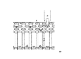
図1は本発明の1実施の形態に従うナノタイタープレートの破断図であって、その複数の貫通孔ウェルの1つが液体試料を保持する1つの移送ピンによって装填されているところを示すものである。プラテン10は、該プラテン10を1つの平面14から他の対向する平面(図示省略)まで縦走させる多数の貫通孔ウェル12を含んでいる。プラテン10を0.1mm乃至10mm以上の厚さ、例えば、およそ0.3乃至1.52mm厚、通常0.5mm厚とすることができる。プラテン10の厚みは、貫通孔ウェルが平面14に垂直に配向されるとき、また、貫通孔ウェル12の長さである。ウェルを表面14に対して角度を持たせることによって、ウェル12の長さと容積をいくらか増加させることができる。ウェル12は移送ピンからの液体試料を渡す目標容器である。
FIG. 1 is a cutaway view of a nanotiter plate according to one embodiment of the present invention, showing one of its plurality of through-hole wells being loaded by one transfer pin that holds a liquid sample. . The platen 10 includes a number of through-
貫通孔ウェル12の典型的なミクロ液体容積は0.1ピコリットルから1マイクロリットルであり、通常0.2−100ナノリットルの容積範囲である。試料液体をウェル12にロードするために毛管作用か表面張力を使用してもよい。ウェル12の吸引力を高めるために、容器の目標領域(内壁42)は試料液体を引き付ける親水性表面を有してもよい。代わりに、ウェル12は試料液体を引き付ける多孔性の親水材料を含んでもよい。プラテン10の外平面14と、ウェル12の開口の周りの材料40の層は、相互汚染(クロストーク)を防ぐために、疎水性材料のものであってもよい。したがって、各ウェル12はいずれの端部においても疎水性領域によって画される親水性領域を有する。
The typical micro liquid volume of the through-
いくつかのシステムにおいて、ウェル12は、パーフルオロ化炭化水素、炭化水素、又はシリコーン系流体などの非混和性の非電導性液体に漬けられる。非混和液はウェル12から試料液体の蒸発を防ぎ、かつ、分配された試料を相互汚染から保護する。もちろん、他の蒸発制御措置も利用することができ、それは、湿度制御、流体圧、プラテン冷却などを含むが、これに制限されるものではない。 In some systems, the well 12 is immersed in an immiscible non-conducting liquid such as a perfluorinated hydrocarbon, hydrocarbon, or silicone-based fluid. The immiscible liquid prevents evaporation of the sample liquid from the well 12 and protects the dispensed sample from cross contamination. Of course, other evaporation control measures can be utilized, including but not limited to humidity control, fluid pressure, platen cooling, and the like.
移送ピン20はほぼ合いくぎのような形状を呈し、ステンレス、チタニウム他の耐久材料で作られていて、平坦、丸、先細り、又はカップ状の先端を有する。通常、移送ピン20の直径は、ピンにより大きい剛性を持たせるため、かつ、ピンをウェルの側壁に確実に接触させてピンとウェル間のドッキングを容易にするためにウェル12の直径よりも大きい。ただし、このことは必ずしも必要ではない。別の方法でははるかに正確なボジショニング措置を必要とするであろう。
The
移送ピン20はまた、その容量を増加させ、かつ/または、分配動作のより良い送り出しを行うために、それに彫り込まれたスロット、溝又は螺旋を有してもよい。スロット、溝、又は螺旋はまた、親水性の容器壁に接触する試料液体の表面積を増加させる。移送ピン20は0.1ピコリットルから10マイクロリットル以上の液体を保持及び/又は配送することができ、通常、0.1ナノリットル乃至4マイクロリットル保持する。
The
図1は、試料液体を保持するテーパ付きスロットを備えるテーパ付き先端を有する移送ピン20の実施の形態を示すものである。そのような実施の形態において、先細り端部はウェル12の内側に嵌ることができるくらい小さいが、全体的ピン直径はウェルの直径よりもなお大きい。図示の実施の形態では、移送ピン20の先細りしている端部は40度の角度を形成し、この端部の中の先細りしているスロットは14度の角度を形成する。この移送ピン20は適切量の試料液体(0.5μlまで)を保持し、試料液体のピンの先端へのウィッキングを容易にし、複数のウェル12を補給なしで連続して満たすことができる。スロット付き端部は、X型を形成する2つの互いにほぼ垂直なスロットを使用してもよい。代替の実施の形態では、移送ピン20は端部に1つ以上のスロットを備える単純なステンレス製の合い釘である。別の実施の形態では、移送ピン20は丸い先端を有し、該先端に1つ以上のスロットを備える単純なステンレス製の合い釘である。
FIG. 1 shows an embodiment of a
プラテン10の表面14に垂線に移送ピン20を自由に動かすことができるようにすることができるが、該動きを表面14に平行な面におけるものに制限することとしてもよい。この実施は浮動ピンと呼ばれる。しかしながら、発明の代替の実施の形態として、固定移送ピン20を使用して実行することもできる。一般に、目標容器、即ち、ウェル12を傷つけることなく、移送ピン20と目標領域の良好な良い接触を達成するのが望ましい。この目的は、浮動モデル移送ピン20を使用するのによって達成されてもよい。浮動重力供給式移送ピン20又はバネ負荷式移送ピン20は、信頼できるように複数のピンを位置決めして各対応するウェル12に適切に接触させるのを助け、小さいアライメントエラーを克服する。いくつかの実施の形態では、バネ負荷式移送ピン20は、望ましくは、作用する力が小さい場合に比較的大きな変形をなすバネ定数を有する「柔らかい」バネを使用することとしてもよい。他の実施の形態において、浮動重力供給式移送ピン20は、浮動重力供給式移送ピン12に最小の力を与えることに関してより有利になることができる。しかしながら、浮動重力供給式移送ピン20は、試料分配サイクルの後の1つの位置で時折張り付くかもしれない。この問題への1つの解決は、移送ピン20を吸い付けて分配サイクル間の位置に戻す真空多岐管のようなピン位置を補助する圧力式又は真空方式の多岐管を使用することである。浮動移送ピン20はまたピンの位置決めに、ピンを一様に延伸させるための強い磁場の使用、磁気ピンの使用、個々のピン又はアレイ全体を加速し急速に減速させる等の磁気か電磁気を使用してもよい。
The
通常、移送ピン20にはプラテン10に移送すべき試料液体が装填されている。試料液体は典型的な実施の形態では、水溶液、DMSO溶液、ジメチルホルムアミド(DMF)溶液、又はアセトニトリル溶液である。次に、移送ピン20はそういった溶液が装填されるべきウェル12の上方位置に移動される。移送ピン20はウェル12の開口に接触するまで下ろされる。移送ピン20の先端が図1で示されるように先細りであるとき、ピンの外表面とウェル12の内壁42の表面の間に最大限度の接触がある。移送ピン20内に保持されている試料液体は該ピンからの移送を生じさせるためにウェル12の内壁42に接触する必要があるので、ピン先端とウェル壁とのそのような最大限度の接触は望ましい。その上、テーパ付きピン先端は、そのテーパが移送ピン20を正確な必要位置に案内するので、ウェルに関してピン配置のわずかなエラーを矯正することができる。
Usually, the
ウェル12(又はウェルのアレイ)に関する移送ピン20(又は移送ピンのアレイ)の適切な位置決めは、ウェル試料液体の移送ピン20からウェル12への移送を生じさせるのに十分な接触をなすために重要である。これは、例えば、正確に機械加工されたガイドプレートを用い、このガイドプレートの少なくとも1つの孔に移送ピン20を通して適切位置に保持することで達成されうる。1実施の形態では、ガイドプレート孔の直径は移送ピンの直径よりもわずかに大きく、そのため、ピンがウェル12と接触するように運ばれるときにピンは最適位置に滑り込むことができるようになる。別の実施の形態では、低位ガイドプレートが上側ガイドプレートの案内孔よりも小さい直径の案内孔を有する2枚のガイドプレートを使用して移送ピン20を位置決めすることとしてもよい。移送ピン20はその下方への運行を制限する肩を有してもよいが、ピンがウェル12にドッキングするときに生じる力に対応して移送ピン20を上向きに動かす。移送ピン20とウェル12の微細な位置決めはどちらか一方を振動させることにより支援されてもよい。
Proper positioning of the transfer pin 20 (or array of transfer pins) with respect to the well 12 (or array of wells) in order to make sufficient contact to cause transfer of the well sample liquid from the
移送ピン20がいったんウェルの開口に接触して置かれると、ピン12の中の試料液体の一部は毛管作用によってウェル12へ吸い寄せられ(そこに前もって格納していることができる非混和液を置き換え)る。試料液体の移送される量は、ウェル12の容積によって、かつ、非混和性流体の下に目標領域があるか否かのいずれにせよ、親水性及び疎水性の材料の層の作用などの他の環境変数によって自己計量送り出しされ、もしも、非混和性流体の下に目標領域があるならば、目標領域の上方の非混和性流体の高さ、該領域との接触時間、該領域からの引き出し速度、及びピン移送に関して上に列記した他の変数によって自己計量送り出しされる。従来技術では、通常液体が予め装填された384ウェルプレートなどのウェルに試料液体が移送されていたし、ピンは容器ウェルよりも実質的に小さかった。本発明のいくつかの実施の形態では、試料液体をウェル12に移す前では、ウェル12を実質的に空の状態とすることができる。
Once the
ウィッキング動作を開始させ、かつ、ウェル12の内壁42を濡らすことは、移動過程において重要な点である。いくつかの実施の形態においては、試料液体をウェル12へ自己計量送り出し移送させることができるような良好な接触を、移送ピン20により保持された試料液体と、ウェル12の内壁42の間に確立することは全く困難ではないであろう。いくつかの要素がこの動作能力を生じさせることに影響する。そのような要素は、内壁42が十分親水性でなければならということと、試料液体の露出表面積を最大にするために移送ピン20のピン先端に1つ以上のスロットを使用することである。望ましくは、スロットはリザーバとしての空洞と、移送される量が該スロットリザーバによって保持される総容積のわずかな部分になるようにすることによって、(複数の装填サイクルで分与される容積の標準偏差に関連する)装填変化係数を最小にする形状とを有することが望ましい。移送ピン20のスロットリザーバはまた、ソースマイクロプレートからの試料の1回の装填によりピンから多数の試料の移送を行うというオプションを提供する。
Initiating the wicking operation and wetting the inner wall 42 of the well 12 are important points in the movement process. In some embodiments, good contact is established between the sample liquid held by the
さまざまな理由(その一部はよく分かっていない)により、このウィッキング流動を確立することは時折困難であろう。いくつかの実施の形態において、高電圧を印加することによって、格納容器への試料液体の移送を生じさせる難しさが克服される。このアプローチは非極性試料液体の場合に役立つことができるであろうし、特に、水溶液、DMSO溶液、メチルホルムアミド(DMF)溶液、あるいはアセトニトリル溶液のような極性試料液体の場合に特別に役立つ。試料液体で満たされた移送ピン20を目標ウェル12に接触させ、かつ、低電流(通常5マイクロアンペア未満)の高電圧を印加することにより溶液を目標ウェル12内へ移送することができる。毛管作用の開始もまた、、移送ピン20か目標ウェル12を振動させることによって支援することができる。
It may be difficult to establish this wicking flow for various reasons, some of which are not well understood. In some embodiments, the difficulty of causing transfer of sample liquid to the containment vessel is overcome by applying a high voltage. This approach could be useful for non-polar sample liquids, and is particularly useful for polar sample liquids such as aqueous solutions, DMSO solutions, methylformamide (DMF) solutions, or acetonitrile solutions. The solution can be transferred into the target well 12 by bringing the
本発明のいくつかの実施の形態において、図1に関して上で説明した既存の移送ピンとプラテンウェル構成を使用し、移送ピン20又は少なくとも該ピンの先端に高電圧を印加する。この構成処理は、前記米国特許第6,149,815’815号において(その図1で示されるように)説明されている複雑なプレート絶縁処理の必要性を避けるという構成とは異なっている。また、米国特許第6,149,815’815号は移送される量に電圧−時間の動電関係を使用しない。移送ピン20が容器目標部に直接接触する実施の形態では、移送ピン20に印加された電荷は試料液体の移送時間又は分配量に直接関連していない。その目的は内壁42の親水吸引性とプラテンウェル12の自己計量送り出し動作によって達成される。移送ピン20に与える電荷は、むしろ、移送ピン20が保持する試料を励起させて、移送ピン20と、ウェル12の内壁42の間の液柱流れチャンネルを濡らす活性化エネルギとして作用する。特定の実施の形態において、分配される試料液体量は、ピンの形状、ピンの被覆、試料液体の表面張力、濡れ深さ、移送速度、試料液体の粘性、試料液体の導電性、試料液体中の粒子の濃度、電圧レベル、電圧印加時間、電圧周波数、及び装填環境(例えば、空気対過少液体)に依存する。これらの変数を慎重に制御することが必要である。いくつかの実施の形態では、移送ピン20よりむしろウェル12に電圧を印加する方が役に立つ。
In some embodiments of the present invention, the existing transfer pin and platen well configuration described above with respect to FIG. 1 is used to apply a high voltage to transfer
サンプル液体の移送に必要な電圧は試料液体と、容器、すなわち、ウェル12の物理的性質に依存し、この特性は試料液体と、容器(ウェル)の相互の親和性を含む。さらに、交流又は直流電圧の選択は試料液体の移送に必要な電圧に影響するであろうが、両方のタイプの使用が可能である。一般に、10V乃至50kVの電圧、通常、100V乃至5kVの範囲の電圧である。電圧レベルの選択はオーム性関連の加熱特性及び物質破壊特性の効果によって影響される。高誘電定数液体の場合、大電圧パルスの高電圧を電気絶縁破壊なしで適用してもよい。 The voltage required for the transfer of the sample liquid depends on the physical properties of the sample liquid and the container, i.e. well 12, which characteristics include the mutual affinity of the sample liquid and the container (well). Furthermore, the choice of AC or DC voltage will affect the voltage required for the transfer of the sample liquid, but both types of use are possible. Generally, it is a voltage in the range of 10V to 50kV, usually in the range of 100V to 5kV. The choice of voltage level is influenced by the effects of ohmic related heating and material breakdown properties. In the case of a high dielectric constant liquid, a high voltage of a high voltage pulse may be applied without electrical breakdown.
試料液体、容器、ピン、空気、又は非混和性流体の電気的加熱、エッチング、及びイオン化を防ぐために、移送ピン20から流れる電流を制限することが望ましい。したがって、高電圧低電流システムを使用することが重要である。高電圧低電流原の例は、バン・デ・グラーフ(Van de Graaf)ジェネレータ、又は高電圧高抵抗に直列接続された標準高電圧源を含む。
In order to prevent electrical heating, etching, and ionization of sample liquids, containers, pins, air, or immiscible fluids, it is desirable to limit the current flowing from the
1特定の実施の形態において、電圧は移送ピン20が目標ウェル12の開口に置かれた後に移送ピン20に印加され、該電圧は、試料液体が該ウェル12に移され、移送ピン20が該ウェル12の開口から引き出された後に取り除かれる。他の実施の形態において、電圧は、移送ピン20が目標ウェル12の開口に置かれる前に移送ピン20に印加され、該電圧は、試料液体が該ウェル12に移された後、移送ピン20が該ウェル12の開口から引き出される前に取り除かれる。
In one particular embodiment, the voltage is applied to the
さらに、様々な実施の形態における試料液体の移送を支援する電圧は、移送ピン20と目標ウェル12との物理的接触が完全であり、部分的であり、又は全くない状態に基づくことができる。すなわち、いくつかの実施の形態では、試料液体をピンからウェルまで移すために移送ピン20の端部を目標ウェル12の一部に実質的、物理的に接触させることができる。他の実施の形態では、試料液体をピンからウェルまで移すために、そういった接触を実際に行うことなく、移送ピン20を目標ウェル12の開口に接近させることができる。接触のあるなしにかかわらずいくつかの実施の形態において、電子スプレー効果の恩恵により、試料液体を移送ピン20から目標ウェル12まで移すことができる。
Further, the voltages that assist in the transfer of the sample liquid in various embodiments can be based on full, partial, or no physical contact between the
様々な実施の形態では、目標ウェル12かプラテン10の全体のどちらかを電気的に接地してもよい。他の実施の形態において、プラテン10とウェル12のいずれも接地しなくてもよい。移送ピン20と目標ウェル12間に適切な電圧差がある限り、どちらのアプローチでもうまく移送される。さらに、プラテン10自体は伝導材料又は絶縁性材料で作られていてもよい。そのうえ、特定の実施の形態では、図1に関して説明される親水性及び疎水性の材料の組み合わせを必ずしも必要としないが、意義のある疎水性又は親水性の特性を有していない容器構造、又は、すべて疎水性の材料若しくはすべて親水性の材料を使用することで発明を利用することができる。
In various embodiments, either the target well 12 or the entire platen 10 may be electrically grounded. In other embodiments, neither platen 10 nor well 12 need be grounded. As long as there is an appropriate voltage difference between the
サンプル液体の移送を支援する電圧の効率も移送ピン20と目標ウェル12の相対的な幾何学形状に依存する。例えば、図1で示されるような先細り尖端を有する移送ピン20は平坦な端部などの異なる形よりも効果的である。ウェル12の直径が280ミクロンである1特定の実施の形態では、200ミクロン未満、例えば、140ミクロンのピン尖端は最も効果的であろう。いくつかの特定の実施の形態では、鈍いピン先端も同様に働くであろうが、アンダーデンス流体などの他の実施の形態では、端部が十分に尖っていない鈍いピン先端は、試料液体が移送ピン20の側面を登るかもしれないので、移送支援電圧構成としては動作しない。
The efficiency of the voltage that supports the transfer of the sample liquid also depends on the relative geometry of the
図1で示される個々の移送ピン20の使用に加え、1実施の形態は、それぞれの移送ピン20がプラテン10の1つのウェル12に向けられるように離間された設計である図2に示すような形態の複数ピンのアレイ30に基づくことができる。図2では、複数の移送ピン20は電気絶縁性プレート32によってアレイとして保持されている。移送ピン20の底部は、図2で示されるように溝付きとしてもよいし又は分配ために試料液体を保持するその他の形状としてもよい。さらに、移送ピン20底部を図2で示すように四角にしてもよいし、図1のように先細りとしてもよく、又はその他の形状を有してもよい。
In addition to the use of the individual transfer pins 20 shown in FIG. 1, one embodiment is shown in FIG. 2, which is a spaced design such that each
各移送ピン20の上側を直接又は低抗体、スイッチ又はトランジスタを介して電源に電気的に接続してもよい。その電圧をそれぞれの移送ピン20に特有のものとしても良く、又は複数の移送ピン20が1つの共通の電源を共有してもよい。
The upper side of each
複数の移送ピン20の上側は電圧制御アレイ34のピン複数の電源36に接続されている。電圧制御アレイ34は、オプションとして、外部プロセッサによってアドレス可能な電圧制御ポート38を含んでもよい。それぞれ個々のピン電源36は、例えば、高電圧源に接続された低抗網(すなわち、電圧制御アレイ34)の低抗体要素とすることができ、それにより、それぞれの移送ピン20がそれ自身の低抗体を介して高電圧源へ接続される。システムの費用とサイズを小さくするために、単一電源の低抗体を高電圧源と低抗網の間に置くこととしてもよく、これにより、該網においてより小さくて、より安い低抵抗の低抗体を使用し、かつ、それらの低抗体と共に、電源において単一の嵩張った、より高価な高抵抗の低抗体を使用することができる。例えば、電源低抗体を1〜10ギグオーム(gigohm)の低抗体とすることができ、ピン低抗体をそれぞれ1〜10メガオーム(megohms)とすることができる。しかしながら、ピンアレイ30を通して均質な移送を与えるためには、ピン低抗体を高い抵抗のものとすること、例えば、各ピンがギグオーム低抗体を有することは有利であるかもしれない。
The upper side of the plurality of transfer pins 20 is connected to a plurality of pins 36 of the
電圧を印加して少なくとも1つの移送ピン20を個別に作動させるために、制御可能なスイッチを作動可能ピンに直列に接続して配設することとしてもよい。これらのスイッチを例えば高電圧トランジスタ又はリレーとしてもよく、そして、マイクロプロセッサによって制御してもよい。
A controllable switch may be arranged in series with the actuatable pin in order to apply a voltage and individually actuate the at least one
1つの特定の実施の形態では、それぞれのバネ負荷移送ピン20をプリント回路基板電圧制御アレイ34への電気接触として働くバネに装着してもよい。このプリント回路基板電圧制御アレイ34はまた、低抗網と、高電圧源への接続装置を含んでもよい。いくつかの実施の形態では、プリント回路基板電圧制御アレイ34はまた、スイッチ網と、試料分配パターンを選択するためのコンピュータその他の装置への接続装置を含んでもよい。
In one particular embodiment, each spring loaded
したがって、1実施の形態では、複数ピンのアレイ30のそれぞれの移送ピン20は高電圧をピンに印加する目的で個別にアドレス可能である。そのようなピンアレイ30における1つの移送ピン20が一度に実行可能であってもよいし、複数のピンが一度に実行可能であってもよいし、又はアレイのすべてピンが一度に実行可能であってもよい。一度により多くの移送ピン20が作動するほど、システムの並列処理はより多くなる。複数の移送ピン20の異なるパターンを(コンピュータ用インクジェットプリンタと類似の方法により)作動させることにより、分配された試料のパターンを展開することとしてもよい。この処理を繰り返すことによって、ペプチド、小分子又はオリゴヌクレオチドなどの有機分子の合成を含み、層にされた試料パターンを展開することができる。
Thus, in one embodiment, each
別の実施の形態では、ピンアレイは、移送ピン20のサブセットを選択し、試料をパターンとして分配する目的で、それらのピンを伸長させ縮引させて接触させ又はその接触を解除するコントローラを含むことができる。例えば、容器ウェル12に接触することが望まれない移送ピン20を縮引させるためにソレノイドアレイを使用されることができる。これらのソレノイドは直接又は管アレイにおいて摺動自在に配設されたピストンアレイなどのリモート駆動機構によって移送ピン20を作動させることとしてもよい。この代わりに、真空多岐管か圧力多岐管に接続された制御可能なバルブアレイを用いて移送ピン20のサブセットを選択してそれらのピンを縮引又は伸張することとしてもよい。試料移送のために選択された移送ピン20だけがウェル12の開口に接近できるようにアレイ30のピンを動かすことにより、非選択ピンに電圧が印加されないときでさえ生じるかもしれない濡れ等により液体が非選択ピンから非選択ウェルに誤って移送されることを避けることができる。電子スプレー等による誤った分配を防止するために、運動コントローラと、選択されたピンに高電圧を印加することの両方を用いることで移送ピンパターン20を選択してそれらのピンを作動させることが望ましい。
In another embodiment, the pin array includes a controller that selects a subset of transfer pins 20 and extends or contracts the pins to contact or release the contacts for the purpose of dispensing the sample as a pattern. Can do. For example, a solenoid array can be used to retract transfer pins 20 that are not desired to contact the container well 12. These solenoids may actuate the
発明の例示的な様々な実施の形態が開示されたが、発明の真の範囲から逸脱することなく発明の長所のいくつかを達成する様々な変形と変更をなすことができることは当業者にとって明らかである。 While various exemplary embodiments of the invention have been disclosed, it will be apparent to those skilled in the art that various modifications and variations can be made to achieve some of the advantages of the invention without departing from the true scope of the invention. It is.
Claims (91)
ミクロ液体試料を目標容器へ移送する少なくとも1つの移送ピンを含んでなり、前記少なくとも1つの移送ピンの一端のピン先端は前記目標容器の開口と協働し毛管作用を使用して前記試料を前記少なくとも1つの移送ピンから前記目標容器へ移送するミクロ液体ディスペンサ。 A micro liquid dispenser for an analytical system,
Comprising at least one transfer pin for transferring a micro liquid sample to a target container, wherein the pin tip at one end of the at least one transfer pin cooperates with an opening of the target container and uses capillary action to transfer the sample to the target container. A micro liquid dispenser for transferring from at least one transfer pin to the target container.
ミクロ液体試料を目標容器に移送する少なくとも1つの移送ピンであって、前記目標容器の開口と協働するピン先端を一端に備える移送ピンを提供し、
前記目標容器と前記ピン先端の間に毛管作用を使用して前記試料を前記少なくとも1つの移送ピンから前記目標容器へ移送する、
ことを含んでなる試料分配方法。 A sample dispensing method for dispensing a micro liquid sample, comprising:
Providing at least one transfer pin for transferring a micro liquid sample to a target container, the transfer pin comprising at one end a pin tip cooperating with the opening of the target container;
Transferring the sample from the at least one transfer pin to the target container using capillary action between the target container and the pin tip;
A sample dispensing method comprising:
複数の格納容器を含む少なくとも1つの液体試料格納装置と;
毛管作用を利用してミクロ液体試料を目標格納容器に移送する少なくとも1つの移送ピンを有するミクロ液体ディスペンサであって、前記移送ピンの一端は前記目標容器の開口と協働するように構成されたピン先端を有するミクロ液体ディスペンサと、
前記移送ピンが前記目標容器と協働して前記試料を移送できるように前記液体ディスペンサを配置させるディスペンサ配置モジュールとを、
含んでなるミクロ液体分析システム。 A micro liquid analysis system,
At least one liquid sample storage device comprising a plurality of storage containers;
A micro liquid dispenser having at least one transfer pin for transferring a micro liquid sample to a target containment vessel utilizing capillary action, wherein one end of the transfer pin is configured to cooperate with an opening of the target container. A micro liquid dispenser having a pin tip;
A dispenser placement module for placing the liquid dispenser such that the transfer pin can transport the sample in cooperation with the target container;
A micro liquid analysis system comprising.
Applications Claiming Priority (2)
| Application Number | Priority Date | Filing Date | Title |
|---|---|---|---|
| US10/227,179 US8277753B2 (en) | 2002-08-23 | 2002-08-23 | Microfluidic transfer pin |
| PCT/US2003/026441 WO2004018104A1 (en) | 2002-08-23 | 2003-08-22 | Capillary action transfer pins |
Publications (2)
| Publication Number | Publication Date |
|---|---|
| JP2005536727A true JP2005536727A (en) | 2005-12-02 |
| JP2005536727A5 JP2005536727A5 (en) | 2006-10-19 |
Family
ID=31887419
Family Applications (1)
| Application Number | Title | Priority Date | Filing Date |
|---|---|---|---|
| JP2004529909A Pending JP2005536727A (en) | 2002-08-23 | 2003-08-22 | Capillary transfer pin |
Country Status (6)
| Country | Link |
|---|---|
| US (4) | US8277753B2 (en) |
| EP (1) | EP1536889A1 (en) |
| JP (1) | JP2005536727A (en) |
| AU (1) | AU2003265627A1 (en) |
| CA (1) | CA2495704A1 (en) |
| WO (1) | WO2004018104A1 (en) |
Cited By (4)
| Publication number | Priority date | Publication date | Assignee | Title |
|---|---|---|---|---|
| JP2005315852A (en) * | 2004-03-29 | 2005-11-10 | Kyocera Corp | Liquid print pin, and liquid print method using the same |
| JP2007304096A (en) * | 2006-05-12 | 2007-11-22 | Samsung Electronics Co Ltd | Apparatus and method for printing biomolecular droplet onto substrate |
| JP2015512508A (en) * | 2012-03-16 | 2015-04-27 | ライフ テクノロジーズ コーポレーション | Coated substrates for biological reaction systems |
| JP2020062020A (en) * | 2014-02-18 | 2020-04-23 | ドラッグアレイ, インコーポレイテッド | Multiwell separation unit and agent delivery device |
Families Citing this family (38)
| Publication number | Priority date | Publication date | Assignee | Title |
|---|---|---|---|---|
| US7285422B1 (en) | 1997-01-23 | 2007-10-23 | Sequenom, Inc. | Systems and methods for preparing and analyzing low volume analyte array elements |
| US6893877B2 (en) | 1998-01-12 | 2005-05-17 | Massachusetts Institute Of Technology | Methods for screening substances in a microwell array |
| US20020151040A1 (en) | 2000-02-18 | 2002-10-17 | Matthew O' Keefe | Apparatus and methods for parallel processing of microvolume liquid reactions |
| US20010055765A1 (en) | 2000-02-18 | 2001-12-27 | O'keefe Matthew | Apparatus and methods for parallel processing of micro-volume liquid reactions |
| US20040018615A1 (en) * | 2000-08-02 | 2004-01-29 | Garyantes Tina K. | Virtual wells for use in high throughput screening assays |
| AU2002245047A1 (en) | 2000-10-30 | 2002-07-24 | Sequenom, Inc. | Method and apparatus for delivery of submicroliter volumes onto a substrate |
| US20030148539A1 (en) * | 2001-11-05 | 2003-08-07 | California Institute Of Technology | Micro fabricated fountain pen apparatus and method for ultra high density biological arrays |
| US8277753B2 (en) | 2002-08-23 | 2012-10-02 | Life Technologies Corporation | Microfluidic transfer pin |
| US20060094108A1 (en) * | 2002-12-20 | 2006-05-04 | Karl Yoder | Thermal cycler for microfluidic array assays |
| AU2003302264A1 (en) * | 2002-12-20 | 2004-09-09 | Biotrove, Inc. | Assay apparatus and method using microfluidic arrays |
| US7998435B2 (en) * | 2003-09-19 | 2011-08-16 | Life Technologies Corporation | High density plate filler |
| US20050232821A1 (en) * | 2003-09-19 | 2005-10-20 | Carrillo Albert L | High density plate filler |
| US20050226782A1 (en) * | 2003-09-19 | 2005-10-13 | Reed Mark T | High density plate filler |
| US8277760B2 (en) * | 2003-09-19 | 2012-10-02 | Applied Biosystems, Llc | High density plate filler |
| US20070014694A1 (en) * | 2003-09-19 | 2007-01-18 | Beard Nigel P | High density plate filler |
| US7407630B2 (en) * | 2003-09-19 | 2008-08-05 | Applera Corporation | High density plate filler |
| US20060272738A1 (en) * | 2003-09-19 | 2006-12-07 | Gary Lim | High density plate filler |
| US7570443B2 (en) | 2003-09-19 | 2009-08-04 | Applied Biosystems, Llc | Optical camera alignment |
| US20050220675A1 (en) * | 2003-09-19 | 2005-10-06 | Reed Mark T | High density plate filler |
| US20060233671A1 (en) * | 2003-09-19 | 2006-10-19 | Beard Nigel P | High density plate filler |
| US20060233673A1 (en) * | 2003-09-19 | 2006-10-19 | Beard Nigel P | High density plate filler |
| ATE320009T1 (en) * | 2004-01-15 | 2006-03-15 | Agilent Technologies Inc | POSITIONING SYSTEM AND METHOD FOR A LIQUID TRANSFER DEVICE |
| EP1735097B1 (en) | 2004-03-12 | 2016-11-30 | Life Technologies Corporation | Nanoliter array loading |
| DE102004018006A1 (en) * | 2004-04-14 | 2005-11-10 | Iff International Flavors & Fragrances | Method, device and system for high-precision metering and / or mixing of liquids |
| JP4862167B2 (en) | 2006-04-28 | 2012-01-25 | 国立大学法人山梨大学 | Electrospray ionization method and apparatus |
| WO2009039122A2 (en) | 2007-09-17 | 2009-03-26 | Sequenom, Inc. | Integrated robotic sample transfer device |
| US8889416B2 (en) * | 2010-01-21 | 2014-11-18 | California Institute Of Technology | Methods and devices for micro-isolation, extraction, and/or analysis of microscale components |
| US9085140B2 (en) | 2012-09-05 | 2015-07-21 | Electronics And Telecommunications Research Institute | Active cliche for large-area printing, manufacturing method of the same, and printing method using the same |
| US9914968B2 (en) | 2012-09-26 | 2018-03-13 | Cepheid | Honeycomb tube |
| JP2015534824A (en) * | 2012-11-07 | 2015-12-07 | ライフ テクノロジーズ コーポレーション | Case for containing biological sample and corresponding method of use |
| AU2014348203A1 (en) * | 2013-11-18 | 2016-07-07 | Life Technologies Corporation | Systems and methods for loading liquid samples |
| WO2016115457A1 (en) | 2015-01-16 | 2016-07-21 | California Institute Of Technology | Methods and devices for micro-isolation, extraction, and/or analysis of microscale components in an array |
| KR102473981B1 (en) | 2015-03-24 | 2022-12-05 | 프리시젼바이오 주식회사 | Specimen Inspection Apparatus |
| WO2019147272A1 (en) * | 2018-01-26 | 2019-08-01 | Hewlett-Packard Development Company, L.P. | Dispenser stages |
| WO2019169395A1 (en) * | 2018-03-02 | 2019-09-06 | uBiome, Inc. | Method and system for high-throughput particle handling by use of magnetic fields and device |
| US10861714B2 (en) * | 2019-01-15 | 2020-12-08 | Asm Technology Singapore Pte Ltd | Heating of a substrate for epoxy deposition |
| JPWO2020255641A1 (en) * | 2019-06-20 | 2020-12-24 | ||
| WO2023283452A2 (en) | 2021-07-09 | 2023-01-12 | Cepheid | High-level multiplexing reaction vessel, reagent spotting device and associated methods |
Citations (16)
| Publication number | Priority date | Publication date | Assignee | Title |
|---|---|---|---|---|
| US3252331A (en) * | 1964-11-23 | 1966-05-24 | Cooke Engineering Company | Laboratory apparatus |
| JPH0961310A (en) * | 1995-08-28 | 1997-03-07 | Kdk Corp | Liquid sample transferring method and liquid sample analyzing test tool |
| JPH10503841A (en) * | 1994-06-17 | 1998-04-07 | ザ ボード オブ トランティーズ オブ ザ レランド スタンフォード ジュニア ユニバーシティー | Method and apparatus for creating a microarray comprising a biological sample |
| JP2000028623A (en) * | 1998-07-13 | 2000-01-28 | Aloka Co Ltd | Dispenser |
| US6024925A (en) * | 1997-01-23 | 2000-02-15 | Sequenom, Inc. | Systems and methods for preparing low volume analyte array elements |
| JP2000088863A (en) * | 1998-09-11 | 2000-03-31 | Nippon Laser Denshi Kk | Dispensing needle body for microdispenser |
| JP2000287670A (en) * | 1999-02-03 | 2000-10-17 | Kaken Kogyo:Kk | Transcribing member for liquid and its device |
| JP2001501967A (en) * | 1996-11-06 | 2001-02-13 | シークエノム・インコーポレーテツド | Compositions and methods for immobilizing nucleic acids on a solid support |
| JP2001083164A (en) * | 1999-09-17 | 2001-03-30 | Fuji Photo Film Co Ltd | Hard micro-array |
| JP2001211873A (en) * | 2000-02-03 | 2001-08-07 | Mitsubishi Chemicals Corp | Spotting head |
| JP2002500373A (en) * | 1998-01-12 | 2002-01-08 | マサチューセッツ インスティテュート オブ テクノロジー | Microanalysis method and apparatus |
| JP2002500098A (en) * | 1998-01-09 | 2002-01-08 | カーティージャン テクノロジーズ、 インコーポレイテッド | High-speed dot array ejection method and apparatus |
| JP2002027984A (en) * | 2000-07-17 | 2002-01-29 | Mitsubishi Chemicals Corp | Microreactor chip, method for testing chemical reaction, and thin film material for microreator chip |
| WO2002030561A2 (en) * | 2000-10-10 | 2002-04-18 | Biotrove, Inc. | Apparatus for assay, synthesis and storage, and methods of manufacture, use, and manipulation thereof |
| JP2002189033A (en) * | 2000-12-22 | 2002-07-05 | Furuno Electric Co Ltd | Method and system for dispensing, and tip stocker device |
| WO2002055199A2 (en) * | 2000-10-30 | 2002-07-18 | Sequenom Inc | Method and apparatus for delivery of submicroliter volumes onto a substrate |
Family Cites Families (293)
| Publication number | Priority date | Publication date | Assignee | Title |
|---|---|---|---|---|
| US399396A (en) * | 1889-03-12 | Snare-strainer for drums | ||
| US451188A (en) * | 1891-04-28 | Fan attachment for rocking-chairs | ||
| US1236137A (en) | 1916-11-24 | 1917-08-07 | Harry Bastow | Headlight. |
| US2745001A (en) * | 1951-12-15 | 1956-05-08 | Edwin F Guth | Light diffusors for illuminating devices |
| US2771398A (en) | 1953-09-17 | 1956-11-20 | Thomas L Snyder | Method and apparatus for counting microorganisms |
| US3043669A (en) | 1960-09-21 | 1962-07-10 | Charles Harold | Chemical testing means |
| US3170980A (en) * | 1962-05-09 | 1965-02-23 | Rca Corp | Optical tunnel system |
| JPS5518906B1 (en) | 1971-02-18 | 1980-05-22 | ||
| US3768974A (en) | 1971-03-22 | 1973-10-30 | Sterilizer Control Royalties | Disposable colorimetric indicator device for measuring the concentration of chlorine in water |
| US3666421A (en) | 1971-04-05 | 1972-05-30 | Organon | Diagnostic test slide |
| GB1320426A (en) * | 1971-07-06 | 1973-06-13 | Pfizer | Multiple solution testing device |
| US3997396A (en) | 1973-07-02 | 1976-12-14 | Monsanto Company | Method for the in vitro propagation and maintenance of cells |
| US3864512A (en) * | 1974-02-13 | 1975-02-04 | Theodore B Meadow | Cover for utility outlet |
| US4110165A (en) | 1974-04-20 | 1978-08-29 | Beecham Group Limited | Process for the production of clavulanic acid |
| US4007010A (en) * | 1974-07-03 | 1977-02-08 | Woodbridge Iii Richard G | Blister plane apparatus for testing samples of fluid |
| SE399768B (en) | 1975-09-29 | 1978-02-27 | Lilja Jan E | CYVETT FOR SAMPLING, MIXING OF, THE SAMPLE WITH A REAGENTS AND DIRECT PERFORMANCE OF, SPECIAL OPTICAL, ANALYSIS OF THE SAMPLE MIXED WITH THE REAGENTS |
| US4065263A (en) | 1976-04-02 | 1977-12-27 | Woodbridge Iii Richard G | Analytical test strip apparatus |
| US4111754A (en) | 1976-11-29 | 1978-09-05 | Hydow Park | Immunological testing devices and methods |
| US4273877A (en) | 1978-06-13 | 1981-06-16 | National Research Development Corporation | Spiral plating apparatus |
| US4234316A (en) | 1979-04-02 | 1980-11-18 | Fmc Corporation | Device for delivering measured quantities of reagents into assay medium |
| US4458066A (en) | 1980-02-29 | 1984-07-03 | University Patents, Inc. | Process for preparing polynucleotides |
| US4500707A (en) * | 1980-02-29 | 1985-02-19 | University Patents, Inc. | Nucleosides useful in the preparation of polynucleotides |
| US4453805A (en) | 1981-02-19 | 1984-06-12 | Bell Telephone Laboratories, Incorporated | Optical grating using a liquid suspension of dielectric particles |
| US4415732A (en) | 1981-03-27 | 1983-11-15 | University Patents, Inc. | Phosphoramidite compounds and processes |
| US4973679A (en) | 1981-03-27 | 1990-11-27 | University Patents, Inc. | Process for oligonucleo tide synthesis using phosphormidite intermediates |
| JPS57175957A (en) * | 1981-04-24 | 1982-10-29 | Chugai Pharmaceut Co Ltd | Measuring method and device for antigen- antibody reaction |
| US4562045A (en) | 1981-10-07 | 1985-12-31 | Murata Manufacturing Co. | Carrier for holding analytical samples |
| US5310674A (en) * | 1982-05-10 | 1994-05-10 | Bar-Ilan University | Apertured cell carrier |
| US4613573A (en) | 1982-05-20 | 1986-09-23 | Hitachi, Ltd. | Automatic bacterial colony transfer apparatus |
| US4734192A (en) * | 1982-07-01 | 1988-03-29 | Millipore Corporation | Multiwell membrane filtration apparatus |
| US4861448A (en) | 1982-11-18 | 1989-08-29 | The Trustees Of Columbia University In The City Of New York | Electrophoretic methods employing gel inserts |
| US4663163A (en) * | 1983-02-14 | 1987-05-05 | Hou Kenneth C | Modified polysaccharide supports |
| US4761378A (en) | 1983-03-04 | 1988-08-02 | American Home Products Corp. (Del.) | Microbiological testing apparatus |
| US4659677A (en) | 1983-05-26 | 1987-04-21 | Eastman Kodak Company | Method providing liquid mixing outside containers |
| US4626509A (en) | 1983-07-11 | 1986-12-02 | Data Packaging Corp. | Culture media transfer assembly |
| US4493815A (en) * | 1983-07-28 | 1985-01-15 | Bio-Rad Laboratories, Inc. | Supporting and filtering biochemical test plate assembly |
| US4861722A (en) | 1983-08-24 | 1989-08-29 | Ajinomoto Company, Inc. | Coryneform bacteria carrying recombinant plasmids and their use in the fermentative production of L-lysine |
| US4562871A (en) | 1984-03-16 | 1986-01-07 | Astle Thomas W | Rehydrator |
| FR2568138B1 (en) * | 1984-07-25 | 1986-11-14 | Are Sarl | FILTER CARTRIDGE WITH EXTERNAL HONEYCOMB SURFACE AND METHOD OF MAKING |
| US4586546A (en) | 1984-10-23 | 1986-05-06 | Cetus Corporation | Liquid handling device and method |
| US4722515A (en) | 1984-11-06 | 1988-02-02 | Spectrum Control, Inc. | Atomizing device for vaporization |
| US4683195A (en) | 1986-01-30 | 1987-07-28 | Cetus Corporation | Process for amplifying, detecting, and/or-cloning nucleic acid sequences |
| US4965188A (en) | 1986-08-22 | 1990-10-23 | Cetus Corporation | Process for amplifying, detecting, and/or cloning nucleic acid sequences using a thermostable enzyme |
| US4683202A (en) | 1985-03-28 | 1987-07-28 | Cetus Corporation | Process for amplifying nucleic acid sequences |
| US5038852A (en) | 1986-02-25 | 1991-08-13 | Cetus Corporation | Apparatus and method for performing automated amplification of nucleic acid sequences and assays using heating and cooling steps |
| US5333675C1 (en) | 1986-02-25 | 2001-05-01 | Perkin Elmer Corp | Apparatus and method for performing automated amplification of nucleic acid sequences and assays using heating and cooling steps |
| US6197563B1 (en) * | 1985-03-28 | 2001-03-06 | Roche Molecular Systems, Inc. | Kits for amplifying and detecting nucleic acid sequences |
| US5656493A (en) | 1985-03-28 | 1997-08-12 | The Perkin-Elmer Corporation | System for automated performance of the polymerase chain reaction |
| US4678894A (en) | 1985-04-18 | 1987-07-07 | Baxter Travenol Laboratories, Inc. | Sample identification system |
| US4701304A (en) | 1985-04-19 | 1987-10-20 | Applied Protein Technologies, Inc. | Apparatus for automated synthesis of peptides |
| US4682891A (en) | 1985-05-31 | 1987-07-28 | Health Research, Incorporated | Microcircle system |
| US4682890A (en) | 1985-05-31 | 1987-07-28 | Health Research, Incorporated | Microsample holder and carrier therefor |
| US5047215A (en) | 1985-06-18 | 1991-09-10 | Polyfiltronics, Inc. | Multiwell test plate |
| US4873633A (en) | 1985-10-18 | 1989-10-10 | Cetus Corporation | User controlled off-center light absorbance reading adjuster in a liquid handling and reaction system |
| CA1339653C (en) | 1986-02-25 | 1998-02-03 | Larry J. Johnson | Appartus and method for performing automated amplification of nucleic acid sequences and assays using heating and cooling steps |
| US5153319A (en) | 1986-03-31 | 1992-10-06 | University Patents, Inc. | Process for preparing polynucleotides |
| US5407800A (en) * | 1986-08-22 | 1995-04-18 | Hoffmann-La Roche Inc. | Reverse transcription with Thermus thermophilus polymerase |
| US5561058A (en) | 1986-08-22 | 1996-10-01 | Hoffmann-La Roche Inc. | Methods for coupled high temperatures reverse transcription and polymerase chain reactions |
| US5310652A (en) | 1986-08-22 | 1994-05-10 | Hoffman-La Roche Inc. | Reverse transcription with thermostable DNA polymerase-high temperature reverse transcription |
| US5322770A (en) | 1989-12-22 | 1994-06-21 | Hoffman-Laroche Inc. | Reverse transcription with thermostable DNA polymerases - high temperature reverse transcription |
| US5000921A (en) * | 1986-10-24 | 1991-03-19 | Hanaway Richard W | Multiple pipette samples |
| US5175209A (en) | 1987-01-06 | 1992-12-29 | Baylor College Of Medicine | Porous wafer for segmented synthesis of biopolymers |
| US4834946A (en) * | 1987-02-05 | 1989-05-30 | Levin Andrew E | Apparatus for blot screening numerous, small volume, antibody solutions |
| US5077085A (en) | 1987-03-06 | 1991-12-31 | Schnur Joel M | High resolution metal patterning of ultra-thin films on solid substrates |
| DE3709278A1 (en) | 1987-03-20 | 1988-09-29 | Kernforschungsz Karlsruhe | METHOD FOR PRODUCING FINE-STRUCTURED BODIES |
| US5525464A (en) | 1987-04-01 | 1996-06-11 | Hyseq, Inc. | Method of sequencing by hybridization of oligonucleotide probes |
| US5202231A (en) | 1987-04-01 | 1993-04-13 | Drmanac Radoje T | Method of sequencing of genomes by hybridization of oligonucleotide probes |
| US4828386A (en) * | 1987-06-19 | 1989-05-09 | Pall Corporation | Multiwell plates containing membrane inserts |
| US5108926A (en) * | 1987-09-08 | 1992-04-28 | Board Of Regents, The University Of Texas System | Apparatus for the precise positioning of cells |
| US4893886A (en) * | 1987-09-17 | 1990-01-16 | American Telephone And Telegraph Company | Non-destructive optical trap for biological particles and method of doing same |
| JPH076998B2 (en) | 1987-12-04 | 1995-01-30 | 富士写真フイルム株式会社 | Automatic dispenser and spotting method |
| US4990459A (en) * | 1988-04-25 | 1991-02-05 | Kabushiki Kaisha Toshiba | Impurity measuring method |
| US5204268A (en) | 1988-06-02 | 1993-04-20 | Fuji Photo Film Co., Ltd. | Method and apparatus for applying liquid samples |
| US6147198A (en) | 1988-09-15 | 2000-11-14 | New York University | Methods and compositions for the manipulation and characterization of individual nucleic acid molecules |
| US5108704A (en) * | 1988-09-16 | 1992-04-28 | W. R. Grace & Co.-Conn. | Microfiltration apparatus with radially spaced nozzles |
| FR2637687B1 (en) * | 1988-10-11 | 1991-01-11 | Inst Textile De France | SINGLE USE DEVICE FOR BIOLOGICAL TESTS |
| US5200051A (en) | 1988-11-14 | 1993-04-06 | I-Stat Corporation | Wholly microfabricated biosensors and process for the manufacture and use thereof |
| US4932806A (en) | 1989-03-21 | 1990-06-12 | The United States Of America As Represented By The Administrator Of The National Aeronautics And Space Administration | Compliant joint |
| EP0391674B1 (en) * | 1989-04-05 | 1996-03-20 | New York University | A method for characterising particles |
| US5504007A (en) * | 1989-05-19 | 1996-04-02 | Becton, Dickinson And Company | Rapid thermal cycle apparatus |
| US5744101A (en) * | 1989-06-07 | 1998-04-28 | Affymax Technologies N.V. | Photolabile nucleoside protecting groups |
| US5242974A (en) | 1991-11-22 | 1993-09-07 | Affymax Technologies N.V. | Polymer reversal on solid surfaces |
| US5143854A (en) | 1989-06-07 | 1992-09-01 | Affymax Technologies N.V. | Large scale photolithographic solid phase synthesis of polypeptides and receptor binding screening thereof |
| DE3919690A1 (en) | 1989-06-16 | 1990-12-20 | Behringwerke Ag | INCUBATION TUBE |
| DE3924454A1 (en) | 1989-07-24 | 1991-02-07 | Cornelis P Prof Dr Hollenberg | THE APPLICATION OF DNA AND DNA TECHNOLOGY FOR THE CONSTRUCTION OF NETWORKS FOR USE IN CHIP CONSTRUCTION AND CHIP PRODUCTION (DNA CHIPS) |
| US5219727A (en) | 1989-08-21 | 1993-06-15 | Hoffmann-Laroche Inc. | Quantitation of nucleic acids using the polymerase chain reaction |
| US5262128A (en) | 1989-10-23 | 1993-11-16 | The United States Of America As Represented By The Department Of Health And Human Services | Array-type multiple cell injector |
| US5100627A (en) * | 1989-11-30 | 1992-03-31 | The Regents Of The University Of California | Chamber for the optical manipulation of microscopic particles |
| US5041266A (en) | 1989-12-21 | 1991-08-20 | Hoffmann-La Roche Inc. | Tray for immunometric determinations |
| US5229163A (en) | 1989-12-21 | 1993-07-20 | Hoffmann-La Roche Inc. | Process for preparing a microtiter tray for immunometric determinations |
| AU653712B2 (en) * | 1990-02-16 | 1994-10-13 | F. Hoffmann-La Roche Ag | Improvements in the specificity and convenience of the polymerase chain reaction |
| ATE154981T1 (en) | 1990-04-06 | 1997-07-15 | Perkin Elmer Corp | AUTOMATED MOLECULAR BIOLOGY LABORATORY |
| US5427908A (en) | 1990-05-01 | 1995-06-27 | Affymax Technologies N.V. | Recombinant library screening methods |
| US5621094A (en) * | 1990-05-14 | 1997-04-15 | Quadrant Holdings Cambridge Limited | Method of preserving agarose gel structure during dehydration by adding a non-reducing glycoside of a straight-chain sugar alcohol |
| JPH0678978B2 (en) | 1990-05-25 | 1994-10-05 | スズキ株式会社 | Aggregation pattern detector |
| GB9014263D0 (en) * | 1990-06-27 | 1990-08-15 | Dixon Arthur E | Apparatus and method for spatially- and spectrally- resolvedmeasurements |
| US5243037A (en) * | 1990-09-21 | 1993-09-07 | E. I. Du Pont De Nemours And Company | Poly(fluoroalkyl) sugar reagents for surface modification of supports |
| JPH04169839A (en) | 1990-11-01 | 1992-06-17 | Mitsubishi Electric Corp | Alcohol-content detecting apparatus |
| EP0486927A1 (en) | 1990-11-20 | 1992-05-27 | Air Products And Chemicals, Inc. | Deposition of tungsten films from mixtures of tungsten hexafluoride, organohydrosilanes and hydrogen |
| US6703236B2 (en) * | 1990-11-29 | 2004-03-09 | Applera Corporation | Thermal cycler for automatic performance of the polymerase chain reaction with close temperature control |
| KR100236506B1 (en) * | 1990-11-29 | 2000-01-15 | 퍼킨-엘머시터스인스트루먼츠 | Apparatus for polymerase chain reaction |
| JPH04250874A (en) | 1991-01-09 | 1992-09-07 | Canon Inc | Liquid introducing device |
| US5955377A (en) | 1991-02-11 | 1999-09-21 | Biostar, Inc. | Methods and kits for the amplification of thin film based assays |
| US6004744A (en) | 1991-03-05 | 1999-12-21 | Molecular Tool, Inc. | Method for determining nucleotide identity through extension of immobilized primer |
| US5284753A (en) * | 1991-03-20 | 1994-02-08 | Neuro Probe, Inc. | Multiple-site chemotactic test apparatus and method |
| US5210021A (en) * | 1991-03-20 | 1993-05-11 | Neuro Probe, Inc. | Multiple-site chemotactic test apparatus and method |
| US5466583A (en) | 1991-05-01 | 1995-11-14 | Thomson; Kenneth S. | Method and apparatus for performing 3-dimensional antibiotic susceptibility tests |
| US5994056A (en) | 1991-05-02 | 1999-11-30 | Roche Molecular Systems, Inc. | Homogeneous methods for nucleic acid amplification and detection |
| US5382985A (en) * | 1991-06-14 | 1995-01-17 | The United States Of America As Represented By The Secretary Of The Air Force | Thermorefractive optical switch |
| US5322019A (en) | 1991-08-12 | 1994-06-21 | Terra Tek Inc | System for the initiation of downhole explosive and propellant systems |
| US5373803A (en) | 1991-10-04 | 1994-12-20 | Sony Corporation | Method of epitaxial growth of semiconductor |
| US5605662A (en) | 1993-11-01 | 1997-02-25 | Nanogen, Inc. | Active programmable electronic devices for molecular biological analysis and diagnostics |
| US5632957A (en) * | 1993-11-01 | 1997-05-27 | Nanogen | Molecular biological diagnostic systems including electrodes |
| JP3123153B2 (en) | 1991-11-11 | 2001-01-09 | ミノルタ株式会社 | Electrostatic image developing toner and method of manufacturing the same |
| US5290705A (en) * | 1992-01-13 | 1994-03-01 | R. E. Davis Chemical Corporation | Speciman support for optical analysis |
| DE4234086A1 (en) * | 1992-02-05 | 1993-08-12 | Diagen Inst Molekularbio | METHOD FOR DETERMINING NUCLEIC ACID SEQUENCES AMPLIFIED IN VITRO |
| US5888723A (en) * | 1992-02-18 | 1999-03-30 | Johnson & Johnson Clinical Diagnostics, Inc. | Method for nucleic acid amplification and detection using adhered probes |
| US6107059A (en) | 1992-04-29 | 2000-08-22 | Affymax Technologies N.V. | Peptide library and screening method |
| US5585275A (en) | 1992-09-02 | 1996-12-17 | Arris Pharmaceutical Corporation | Pilot apparatus for peptide synthesis and screening |
| US5374525A (en) | 1992-09-30 | 1994-12-20 | University Of Utah Research Foundation | Methods to determine predisposition to hypertension and association of variant angiotensinogen gene and hypertension |
| WO1994008759A1 (en) | 1992-10-16 | 1994-04-28 | Thomas Jefferson University | Method and apparatus for robotically performing sanger dideoxynucleotide dna sequencing reactions |
| US5962316A (en) | 1992-10-16 | 1999-10-05 | Cold Spring Harbor Laboratory | Cell-cycle regulatory proteins, and uses related thereto |
| US5508200A (en) * | 1992-10-19 | 1996-04-16 | Tiffany; Thomas | Method and apparatus for conducting multiple chemical assays |
| US5576220A (en) | 1993-02-19 | 1996-11-19 | Arris Pharmaceutical Corporation | Thin film HPMP matrix systems and methods for constructing and displaying ligands |
| US5670329A (en) | 1993-05-28 | 1997-09-23 | Cardiovascular Diagnostics, Inc. | Method and analytical system for performing fibrinogen assays accurately, rapidly and simply using a rotating magnetic field |
| DE69429038T2 (en) * | 1993-07-28 | 2002-03-21 | Pe Corp Ny Norwalk | Device and method for nucleic acid amplification |
| US5519218A (en) * | 1993-08-04 | 1996-05-21 | Chang; On Kok | Sample holder for spectroscopy |
| JP3488465B2 (en) | 1993-10-28 | 2004-01-19 | ヒューストン・アドバンスド・リサーチ・センター | Microfabricated flow-through porosity device for separately detecting binding reactions |
| US5538848A (en) | 1994-11-16 | 1996-07-23 | Applied Biosystems Division, Perkin-Elmer Corp. | Method for detecting nucleic acid amplification using self-quenching fluorescence probe |
| FR2716263B1 (en) | 1994-02-11 | 1997-01-17 | Pasteur Institut | Method for aligning macromolecules by passing a meniscus and applications in a method for highlighting, separating and / or assaying a macromolecule in a sample. |
| US5453252A (en) | 1994-02-25 | 1995-09-26 | Truett; William L. | Screen cell for spectroscopy |
| US6015880A (en) * | 1994-03-16 | 2000-01-18 | California Institute Of Technology | Method and substrate for performing multiple sequential reactions on a matrix |
| JP2909216B2 (en) | 1994-04-29 | 1999-06-23 | パーキン‐エルマー コーポレイション | Real-time detection device for nucleic acid amplification products |
| US5571639A (en) * | 1994-05-24 | 1996-11-05 | Affymax Technologies N.V. | Computer-aided engineering system for design of sequence arrays and lithographic masks |
| US5508197A (en) * | 1994-07-25 | 1996-04-16 | The Regents, University Of California | High-speed thermal cycling system and method of use |
| US6001229A (en) | 1994-08-01 | 1999-12-14 | Lockheed Martin Energy Systems, Inc. | Apparatus and method for performing microfluidic manipulations for chemical analysis |
| US5985356A (en) | 1994-10-18 | 1999-11-16 | The Regents Of The University Of California | Combinatorial synthesis of novel materials |
| US6121048A (en) | 1994-10-18 | 2000-09-19 | Zaffaroni; Alejandro C. | Method of conducting a plurality of reactions |
| JP2651478B2 (en) * | 1994-12-15 | 1997-09-10 | 春日電機株式会社 | Static elimination method and device |
| US5551487A (en) * | 1995-03-10 | 1996-09-03 | Hewlett-Packard Company | Micro-dispenser for preparing assay plates |
| DE19509094A1 (en) | 1995-03-16 | 1996-09-26 | Boehringer Mannheim Gmbh | Quantitative transmission spectroscopy using sample carriers with networks |
| US5560811A (en) | 1995-03-21 | 1996-10-01 | Seurat Analytical Systems Incorporated | Capillary electrophoresis apparatus and method |
| US5641391A (en) | 1995-05-15 | 1997-06-24 | Hunter; Ian W. | Three dimensional microfabrication by localized electrodeposition and etching |
| US5609828A (en) | 1995-05-31 | 1997-03-11 | bio M erieux Vitek, Inc. | Sample card |
| CA2179364C (en) | 1995-06-27 | 1999-09-28 | Klaus W. Berndt | Method and apparatus for detecting microorganisms |
| US5773238A (en) | 1995-07-07 | 1998-06-30 | Shukla; Ashok K. | Droplet chemical reaction chamber |
| US5785926A (en) | 1995-09-19 | 1998-07-28 | University Of Washington | Precision small volume fluid processing apparatus |
| JPH09126107A (en) * | 1995-11-08 | 1997-05-13 | Sanshin Ind Co Ltd | Operation control device for engine |
| US5763263A (en) | 1995-11-27 | 1998-06-09 | Dehlinger; Peter J. | Method and apparatus for producing position addressable combinatorial libraries |
| USH1919H (en) | 1995-12-01 | 2000-11-07 | E. I. Du Pont De Nemours And Company | Agricultural product microscreen method and apparatus |
| CA2192262C (en) * | 1995-12-08 | 2011-03-15 | Yoshihide Hayashizaki | Method for purification and transfer to separation/detection systems of dna sequencing samples and plates used therefor |
| US5830657A (en) * | 1996-05-01 | 1998-11-03 | Visible Genetics Inc. | Method for single-tube sequencing of nucleic acid polymers |
| TW432073B (en) * | 1995-12-28 | 2001-05-01 | Pfizer | Pyrazolopyridine compounds |
| US5762873A (en) | 1996-02-21 | 1998-06-09 | Biomerieux Vitek, Inc. | Automatic sample testing machine |
| US5849598A (en) | 1996-03-15 | 1998-12-15 | Washington University | Method for transferring micro quantities of liquid samples to discrete locations |
| US6001586A (en) | 1996-03-29 | 1999-12-14 | Genencor International, Inc. | Compartmentalization method for screening microorganisms |
| US5879632A (en) * | 1996-04-09 | 1999-03-09 | Sarnoff Corporation | Apportioning system |
| US5906683A (en) * | 1996-04-16 | 1999-05-25 | Applied Materials, Inc. | Lid assembly for semiconductor processing chamber |
| US6399023B1 (en) * | 1996-04-16 | 2002-06-04 | Caliper Technologies Corp. | Analytical system and method |
| JP2000511629A (en) * | 1996-05-09 | 2000-09-05 | 3―ディメンショナル ファーマシュウティカルズ,インコーポレイテッド | Microplate thermal shift assays and devices for ligand development and multivariate protein chemistry optimization |
| US6103479A (en) | 1996-05-30 | 2000-08-15 | Cellomics, Inc. | Miniaturized cell array methods and apparatus for cell-based screening |
| ATE318327T1 (en) * | 1996-06-04 | 2006-03-15 | Univ Utah Res Found | FLUORESCENCE-DONOR-ACCEPTOR PAIR |
| US5770151A (en) * | 1996-06-05 | 1998-06-23 | Molecular Dynamics, Inc. | High-speed liquid deposition device for biological molecule array formation |
| US5780233A (en) | 1996-06-06 | 1998-07-14 | Wisconsin Alumni Research Foundation | Artificial mismatch hybridization |
| US5779868A (en) | 1996-06-28 | 1998-07-14 | Caliper Technologies Corporation | Electropipettor and compensation means for electrophoretic bias |
| BR9710054A (en) | 1996-06-28 | 2000-01-11 | Caliper Techn Corp | Apparatus for separating test compounds for an effect on a biochemical system and for detecting a effect of a test compound on a biochemical system, procedures for determining whether a sample contains a compound capable of affecting a biochemical system, for separating a plurality of test compounds for an effect on a biochemical system and uses of a microfluidic system and a test substrate. |
| DE19628178C1 (en) | 1996-07-12 | 1997-09-18 | Bruker Franzen Analytik Gmbh | Loading matrix-assisted laser desorption-ionisation sample plate for mass spectrometric analysis |
| JP2002515044A (en) * | 1996-08-21 | 2002-05-21 | スミスクライン・ビーチャム・コーポレイション | A rapid method for sequencing and synthesizing bead-based combinatorial libraries |
| US5795748A (en) | 1996-09-26 | 1998-08-18 | Becton Dickinson And Company | DNA microwell device and method |
| US6136566A (en) | 1996-10-04 | 2000-10-24 | Lexicon Graphics Incorporated | Indexed library of cells containing genomic modifications and methods of making and utilizing the same |
| US5794738A (en) | 1996-11-12 | 1998-08-18 | Rockwell Heavy Vehicle Systems, Inc. | Disc brake with gear driven adjusting piston |
| US6060240A (en) * | 1996-12-13 | 2000-05-09 | Arcaris, Inc. | Methods for measuring relative amounts of nucleic acids in a complex mixture and retrieval of specific sequences therefrom |
| US5944652A (en) | 1996-12-27 | 1999-08-31 | City Of Hope | Method for breeding chickens |
| CA2276462C (en) | 1996-12-31 | 2007-06-12 | Genometrix Incorporated | Multiplexed molecular analysis system apparatus and method |
| US6133709A (en) | 1997-01-21 | 2000-10-17 | Metrixx Limited | Signalling system |
| NO304355B1 (en) | 1997-02-20 | 1998-12-07 | Sinvent As | Multi-autoclave for methodical, automated synthesis of zeolites and other compounds |
| AUPO524897A0 (en) | 1997-02-21 | 1997-03-20 | Johnson & Johnson Research Pty. Limited | Method of amplifying specific nucleic acid target sequences |
| US5958345A (en) | 1997-03-14 | 1999-09-28 | Moxtek, Inc. | Thin film sample support |
| US7133726B1 (en) | 1997-03-28 | 2006-11-07 | Applera Corporation | Thermal cycler for PCR |
| US6143496A (en) * | 1997-04-17 | 2000-11-07 | Cytonix Corporation | Method of sampling, amplifying and quantifying segment of nucleic acid, polymerase chain reaction assembly having nanoliter-sized sample chambers, and method of filling assembly |
| US5985214A (en) | 1997-05-16 | 1999-11-16 | Aurora Biosciences Corporation | Systems and methods for rapidly identifying useful chemicals in liquid samples |
| US5910287A (en) | 1997-06-03 | 1999-06-08 | Aurora Biosciences Corporation | Low background multi-well plates with greater than 864 wells for fluorescence measurements of biological and biochemical samples |
| EP0882593A1 (en) | 1997-06-05 | 1998-12-09 | Xerox Corporation | Method for forming a hydrophobic/hydrophilic front face of an ink jet printhead |
| US5922604A (en) | 1997-06-05 | 1999-07-13 | Gene Tec Corporation | Thin reaction chambers for containing and handling liquid microvolumes |
| US6090251A (en) | 1997-06-06 | 2000-07-18 | Caliper Technologies, Inc. | Microfabricated structures for facilitating fluid introduction into microfluidic devices |
| US6664044B1 (en) | 1997-06-19 | 2003-12-16 | Toyota Jidosha Kabushiki Kaisha | Method for conducting PCR protected from evaporation |
| WO1999004246A1 (en) | 1997-07-14 | 1999-01-28 | Massachusetts Institute Of Technology | Three-dimensional light absorption spectroscopic imaging |
| US6071748A (en) | 1997-07-16 | 2000-06-06 | Ljl Biosystems, Inc. | Light detection device |
| US20020001544A1 (en) * | 1997-08-28 | 2002-01-03 | Robert Hess | System and method for high throughput processing of droplets |
| US6309600B1 (en) | 1997-08-28 | 2001-10-30 | Biotrove, Inc. | Apparatus for droplet microchemistry |
| US5989402A (en) | 1997-08-29 | 1999-11-23 | Caliper Technologies Corp. | Controller/detector interfaces for microfluidic systems |
| EP1009757A1 (en) * | 1997-09-04 | 2000-06-21 | Gryphon Sciences | Modular protein libraries and methods of preparation |
| WO1999015876A1 (en) | 1997-09-19 | 1999-04-01 | Aclara Biosciences, Inc. | Apparatus and method for transferring liquids |
| US5942432A (en) | 1997-10-07 | 1999-08-24 | The Perkin-Elmer Corporation | Apparatus for a fluid impingement thermal cycler |
| US6485944B1 (en) | 1997-10-10 | 2002-11-26 | President And Fellows Of Harvard College | Replica amplification of nucleic acid arrays |
| US6083682A (en) | 1997-12-19 | 2000-07-04 | Glaxo Group Limited | System and method for solid-phase parallel synthesis of a combinatorial collection of compounds |
| US6893877B2 (en) * | 1998-01-12 | 2005-05-17 | Massachusetts Institute Of Technology | Methods for screening substances in a microwell array |
| JP4387588B2 (en) * | 1998-02-04 | 2009-12-16 | メルク エンド カムパニー インコーポレーテッド | Virtual wells for high-throughput screening assays |
| US6251343B1 (en) | 1998-02-24 | 2001-06-26 | Caliper Technologies Corp. | Microfluidic devices and systems incorporating cover layers |
| AU747464B2 (en) | 1998-06-08 | 2002-05-16 | Caliper Technologies Corporation | Microfluidic devices, systems and methods for performing integrated reactions and separations |
| US6274089B1 (en) | 1998-06-08 | 2001-08-14 | Caliper Technologies Corp. | Microfluidic devices, systems and methods for performing integrated reactions and separations |
| US6235473B1 (en) * | 1998-07-02 | 2001-05-22 | Orchid Biosciences, Inc. | Gene pen devices for array printing |
| EP1129008A4 (en) * | 1998-07-07 | 2001-12-05 | Cartesian Technology Inc | Tip design and random access array for microfluidic transfer |
| US6576478B1 (en) | 1998-07-14 | 2003-06-10 | Zyomyx, Inc. | Microdevices for high-throughput screening of biomolecules |
| US6447726B1 (en) | 1998-08-10 | 2002-09-10 | Uab Research Foundation | High density protein crystal growth |
| US6132685A (en) | 1998-08-10 | 2000-10-17 | Caliper Technologies Corporation | High throughput microfluidic systems and methods |
| JP3445501B2 (en) | 1998-09-04 | 2003-09-08 | 日立ソフトウエアエンジニアリング株式会社 | Manufacturing method of sheet-like member laminate and sheet-like probe holder |
| US6103199A (en) | 1998-09-15 | 2000-08-15 | Aclara Biosciences, Inc. | Capillary electroflow apparatus and method |
| US6312103B1 (en) | 1998-09-22 | 2001-11-06 | Hewlett-Packard Company | Self-cleaning titanium dioxide coated ink-jet printer head |
| US6149787A (en) | 1998-10-14 | 2000-11-21 | Caliper Technologies Corp. | External material accession systems and methods |
| US6689323B2 (en) * | 1998-10-30 | 2004-02-10 | Agilent Technologies | Method and apparatus for liquid transfer |
| US6309828B1 (en) | 1998-11-18 | 2001-10-30 | Agilent Technologies, Inc. | Method and apparatus for fabricating replicate arrays of nucleic acid molecules |
| US6271024B1 (en) | 1999-02-18 | 2001-08-07 | The Aerospace Corporation | Compartmental fast thermal cycler |
| US6215894B1 (en) | 1999-02-26 | 2001-04-10 | General Scanning, Incorporated | Automatic imaging and analysis of microarray biochips |
| US6749814B1 (en) * | 1999-03-03 | 2004-06-15 | Symyx Technologies, Inc. | Chemical processing microsystems comprising parallel flow microreactors and methods for using same |
| US6326083B1 (en) | 1999-03-08 | 2001-12-04 | Calipher Technologies Corp. | Surface coating for microfluidic devices that incorporate a biopolymer resistant moiety |
| US6296702B1 (en) | 1999-03-15 | 2001-10-02 | Pe Corporation (Ny) | Apparatus and method for spotting a substrate |
| US6027873A (en) * | 1999-03-19 | 2000-02-22 | Genencor International, Inc. | Multi-through hole testing plate for high throughput screening |
| CN1348396A (en) * | 1999-03-19 | 2002-05-08 | 金克克国际有限公司 | Multi-through hole testing plate for high throughput screening |
| EP1165835A2 (en) * | 1999-03-24 | 2002-01-02 | Serono Genetics Institute S.A. | GENOMIC SEQUENCE OF THE $i(PURH) GENE AND $i(PURH)-RELATED BIALLELIC MARKERS |
| US6773676B2 (en) | 1999-04-27 | 2004-08-10 | Agilent Technologies, Inc. | Devices for performing array hybridization assays and methods of using the same |
| WO2000068671A2 (en) | 1999-05-12 | 2000-11-16 | Aclara Biosciences, Inc. | Multiplexed fluorescent detection in microfluidic devices |
| US6485690B1 (en) | 1999-05-27 | 2002-11-26 | Orchid Biosciences, Inc. | Multiple fluid sample processor and system |
| US6136592A (en) | 1999-06-25 | 2000-10-24 | Leighton; Stephen B. | Multiple micro-arrays |
| US6572828B1 (en) | 1999-07-16 | 2003-06-03 | General Electric Company | Method and apparatus for high-throughput chemical screening |
| US6337435B1 (en) * | 1999-07-30 | 2002-01-08 | Bio-Rad Laboratories, Inc. | Temperature control for multi-vessel reaction apparatus |
| US6713309B1 (en) * | 1999-07-30 | 2004-03-30 | Large Scale Proteomics Corporation | Microarrays and their manufacture |
| US6423536B1 (en) | 1999-08-02 | 2002-07-23 | Molecular Dynamics, Inc. | Low volume chemical and biochemical reaction system |
| US6495104B1 (en) | 1999-08-19 | 2002-12-17 | Caliper Technologies Corp. | Indicator components for microfluidic systems |
| US6858185B1 (en) | 1999-08-25 | 2005-02-22 | Caliper Life Sciences, Inc. | Dilutions in high throughput systems with a single vacuum source |
| JP3715148B2 (en) | 1999-09-17 | 2005-11-09 | 富士写真フイルム株式会社 | High density macro array |
| US6406869B1 (en) | 1999-10-22 | 2002-06-18 | Pharmacopeia, Inc. | Fluorescent capture assay for kinase activity employing anti-phosphotyrosine antibodies as capture and detection agents |
| EP1227887B1 (en) | 1999-10-26 | 2006-01-18 | Tibotec BVBA | Device and related method for delivering small volumes of liquid |
| US6642000B1 (en) | 1999-11-12 | 2003-11-04 | University Of Chicago | PCR amplification on microarrays of gel immobilized oligonucleotides |
| US6149815A (en) | 1999-11-23 | 2000-11-21 | Sauter; Andrew D. | Precise electrokinetic delivery of minute volumes of liquid(s) |
| US6468761B2 (en) | 2000-01-07 | 2002-10-22 | Caliper Technologies, Corp. | Microfluidic in-line labeling method for continuous-flow protease inhibition analysis |
| US6399396B1 (en) | 2000-01-28 | 2002-06-04 | Agilent Technologies, Inc. | Compressed loading apparatus and method for liquid transfer |
| US7169355B1 (en) | 2000-02-02 | 2007-01-30 | Applera Corporation | Apparatus and method for ejecting sample well trays |
| US20020151040A1 (en) | 2000-02-18 | 2002-10-17 | Matthew O' Keefe | Apparatus and methods for parallel processing of microvolume liquid reactions |
| US20010055765A1 (en) | 2000-02-18 | 2001-12-27 | O'keefe Matthew | Apparatus and methods for parallel processing of micro-volume liquid reactions |
| CN1416365A (en) | 2000-02-22 | 2003-05-07 | 基因谱公司 | Microarray fabrication tech and appts. |
| CA2401118A1 (en) | 2000-02-23 | 2001-08-30 | Zyomyx, Inc. | Microfluidic devices and methods |
| US6706538B1 (en) * | 2000-02-29 | 2004-03-16 | Boston Innovation Inc. | Microvolume liquid dispensing array |
| AU2001247329A1 (en) | 2000-03-15 | 2001-09-24 | Aviva Biosciences Corporation | Apparatus and method for high throughput electrorotation analysis |
| US20020003177A1 (en) * | 2000-03-17 | 2002-01-10 | O'connor Stephen D. | Electrostatic systems and methods for dispensing liquids |
| US6878554B1 (en) * | 2000-03-20 | 2005-04-12 | Perkinelmer Las, Inc. | Method and apparatus for automatic pin detection in microarray spotting instruments |
| DE10015380A1 (en) * | 2000-03-28 | 2001-10-11 | Nmi Univ Tuebingen | Microfluidic component and method for surface treatment of such |
| US7867763B2 (en) | 2004-01-25 | 2011-01-11 | Fluidigm Corporation | Integrated chip carriers with thermocycler interfaces and methods of using the same |
| US20050118073A1 (en) | 2003-11-26 | 2005-06-02 | Fluidigm Corporation | Devices and methods for holding microfluidic devices |
| US6943035B1 (en) | 2000-05-19 | 2005-09-13 | Genetix Limited | Liquid dispensing apparatus and method |
| JP3302350B2 (en) | 2000-06-29 | 2002-07-15 | 株式会社東芝 | Electronics |
| US7172859B2 (en) | 2000-07-14 | 2007-02-06 | Transform Pharmaceuticals, Inc. | System and method for optimizing tissue barrier transfer of compounds |
| DE10046224A1 (en) | 2000-09-19 | 2002-03-28 | Merck Patent Gmbh | Unit for parallel incubation of solutions includes frame holding titration plate closely against cover plate, forming tight seal |
| US6353774B1 (en) * | 2000-09-22 | 2002-03-05 | Virtek Engineering Sciences Inc. | High precision vision guided positioning device |
| EP1322430B1 (en) | 2000-09-25 | 2007-01-17 | Picoliter, Inc. | Focused acoustic energy method and device for generating droplets of immiscible fluids |
| US20040209303A1 (en) | 2000-10-03 | 2004-10-21 | Martin Mark T. | Methods and compositions for directed microwave chemistry |
| WO2002028531A1 (en) | 2000-10-06 | 2002-04-11 | Protasis Corporation | Fluid separation conduit cartridge with encryption capability |
| US6582914B1 (en) | 2000-10-26 | 2003-06-24 | Genencor International, Inc. | Method for generating a library of oligonucleotides comprising a controlled distribution of mutations |
| CA2450676C (en) | 2001-03-09 | 2010-03-30 | Biomicro Systems, Inc. | Method and system for microfluidic interfacing to arrays |
| ES2180416B1 (en) | 2001-03-12 | 2004-06-01 | BIOTOOLS BIOTECHNOLOGICAL & MEDICAL LABORATORIES, S.A. | PROCEDURE FOR THE PREPARATION OF STABILIZED REACTION MIXTURES, TOTAL OR PARTIALLY DESIRED, THAT INCLUDE, AT LEAST, ONE ENZYME, REACTION MIXES AND KITS CONTAINING THEM. |
| JP4446621B2 (en) | 2001-03-22 | 2010-04-07 | ミサワホーム株式会社 | Drug penetration method |
| EP1373566B1 (en) | 2001-04-02 | 2009-08-12 | Point-2-Point Genomics Ltd. | Polynucleotide analysis using combinatorial pcr |
| US6812030B2 (en) | 2001-04-25 | 2004-11-02 | Biotrove, Inc. | System and method for high throughput sample preparation and analysis using column chromatography |
| US6649402B2 (en) | 2001-06-22 | 2003-11-18 | Wisconsin Alumni Research Foundation | Microfabricated microbial growth assay method and apparatus |
| US6514750B2 (en) * | 2001-07-03 | 2003-02-04 | Pe Corporation (Ny) | PCR sample handling device |
| EP1439910A2 (en) * | 2001-07-26 | 2004-07-28 | Motorola, Inc. | System and methods for mixing within a microfluidic device |
| US6682702B2 (en) * | 2001-08-24 | 2004-01-27 | Agilent Technologies, Inc. | Apparatus and method for simultaneously conducting multiple chemical reactions |
| US6969489B2 (en) * | 2001-08-24 | 2005-11-29 | Cytoplex Biosciences | Micro array for high throughout screening |
| US20030108726A1 (en) | 2001-10-18 | 2003-06-12 | Schembri Carol T. | Chemical arrays |
| US7300798B2 (en) | 2001-10-18 | 2007-11-27 | Agilent Technologies, Inc. | Chemical arrays |
| US6841663B2 (en) * | 2001-10-18 | 2005-01-11 | Agilent Technologies, Inc. | Chemical arrays |
| AU2002351291A1 (en) * | 2001-12-06 | 2003-06-23 | Nanostream, Inc. | Adhesiveless microfluidic device fabrication |
| US6677151B2 (en) * | 2002-01-30 | 2004-01-13 | Applera Corporation | Device and method for thermal cycling |
| US7022528B2 (en) | 2002-01-31 | 2006-04-04 | Pion, Inc. | Method and apparatus for improving in vitro measurement of membrane permeability of chemical compounds |
| US20040109793A1 (en) | 2002-02-07 | 2004-06-10 | Mcneely Michael R | Three-dimensional microfluidics incorporating passive fluid control structures |
| US6696269B2 (en) | 2002-03-28 | 2004-02-24 | Giles Scientific, Inc. | Microbiological testing method and related apparatus with diffuse-white light emitting diodes |
| US20030207099A1 (en) | 2002-05-01 | 2003-11-06 | Gillmor Susan D. | Low-contact-angle polymer membranes and method for fabricating micro-bioarrays |
| EP1385006A3 (en) | 2002-07-24 | 2004-09-01 | F. Hoffmann-La Roche Ag | System and cartridge for processing a biological sample |
| US7101508B2 (en) * | 2002-07-31 | 2006-09-05 | Agilent Technologies, Inc. | Chemical array fabrication errors |
| US8277753B2 (en) | 2002-08-23 | 2012-10-02 | Life Technologies Corporation | Microfluidic transfer pin |
| US6730883B2 (en) * | 2002-10-02 | 2004-05-04 | Stratagene | Flexible heating cover assembly for thermal cycling of samples of biological material |
| US20040235005A1 (en) | 2002-10-23 | 2004-11-25 | Ernest Friedlander | Methods and composition for detecting targets |
| US7390457B2 (en) | 2002-10-31 | 2008-06-24 | Agilent Technologies, Inc. | Integrated microfluidic array device |
| US20050266582A1 (en) | 2002-12-16 | 2005-12-01 | Modlin Douglas N | Microfluidic system with integrated permeable membrane |
| AU2003302264A1 (en) | 2002-12-20 | 2004-09-09 | Biotrove, Inc. | Assay apparatus and method using microfluidic arrays |
| US20040241636A1 (en) | 2003-05-30 | 2004-12-02 | Michnick Stephen William Watson | Monitoring gene silencing and annotating gene function in living cells |
| EP1662879A4 (en) * | 2003-08-29 | 2009-03-11 | Univ New York | Indirect delivery of growth factors into the central nervous system |
| US20050220675A1 (en) | 2003-09-19 | 2005-10-06 | Reed Mark T | High density plate filler |
| US20050130213A1 (en) | 2003-12-10 | 2005-06-16 | Tom Morrison | Selective ligation and amplification assay |
| US20060057209A1 (en) * | 2004-09-16 | 2006-03-16 | Predicant Biosciences, Inc. | Methods, compositions and devices, including microfluidic devices, comprising coated hydrophobic surfaces |
| US20060105433A1 (en) * | 2004-11-18 | 2006-05-18 | Bickmore William D Jr | Rapid thermocycler |
| DE102005007179A1 (en) | 2005-02-14 | 2006-08-24 | Biotronik Crm Patent Ag | Galvanic cell |
| US8969489B2 (en) | 2010-08-10 | 2015-03-03 | Eastman Chemical Company | Thermosetting coating composition |
-
2002
- 2002-08-23 US US10/227,179 patent/US8277753B2/en active Active
-
2003
- 2003-08-22 EP EP03793336A patent/EP1536889A1/en not_active Withdrawn
- 2003-08-22 JP JP2004529909A patent/JP2005536727A/en active Pending
- 2003-08-22 CA CA002495704A patent/CA2495704A1/en not_active Abandoned
- 2003-08-22 AU AU2003265627A patent/AU2003265627A1/en not_active Abandoned
- 2003-08-22 WO PCT/US2003/026441 patent/WO2004018104A1/en active Application Filing
-
2008
- 2008-04-17 US US12/148,416 patent/US8685340B2/en not_active Expired - Lifetime
-
2014
- 2014-03-24 US US14/222,972 patent/US20140332112A1/en not_active Abandoned
- 2014-07-15 US US14/332,171 patent/US20150038377A1/en not_active Abandoned
Patent Citations (18)
| Publication number | Priority date | Publication date | Assignee | Title |
|---|---|---|---|---|
| US3252331A (en) * | 1964-11-23 | 1966-05-24 | Cooke Engineering Company | Laboratory apparatus |
| JPH10503841A (en) * | 1994-06-17 | 1998-04-07 | ザ ボード オブ トランティーズ オブ ザ レランド スタンフォード ジュニア ユニバーシティー | Method and apparatus for creating a microarray comprising a biological sample |
| JPH0961310A (en) * | 1995-08-28 | 1997-03-07 | Kdk Corp | Liquid sample transferring method and liquid sample analyzing test tool |
| JP2001501967A (en) * | 1996-11-06 | 2001-02-13 | シークエノム・インコーポレーテツド | Compositions and methods for immobilizing nucleic acids on a solid support |
| US6024925A (en) * | 1997-01-23 | 2000-02-15 | Sequenom, Inc. | Systems and methods for preparing low volume analyte array elements |
| JP2002500098A (en) * | 1998-01-09 | 2002-01-08 | カーティージャン テクノロジーズ、 インコーポレイテッド | High-speed dot array ejection method and apparatus |
| JP2002500373A (en) * | 1998-01-12 | 2002-01-08 | マサチューセッツ インスティテュート オブ テクノロジー | Microanalysis method and apparatus |
| JP2000028623A (en) * | 1998-07-13 | 2000-01-28 | Aloka Co Ltd | Dispenser |
| JP2000088863A (en) * | 1998-09-11 | 2000-03-31 | Nippon Laser Denshi Kk | Dispensing needle body for microdispenser |
| JP2000287670A (en) * | 1999-02-03 | 2000-10-17 | Kaken Kogyo:Kk | Transcribing member for liquid and its device |
| JP2001083164A (en) * | 1999-09-17 | 2001-03-30 | Fuji Photo Film Co Ltd | Hard micro-array |
| JP2001211873A (en) * | 2000-02-03 | 2001-08-07 | Mitsubishi Chemicals Corp | Spotting head |
| JP2002027984A (en) * | 2000-07-17 | 2002-01-29 | Mitsubishi Chemicals Corp | Microreactor chip, method for testing chemical reaction, and thin film material for microreator chip |
| WO2002030561A2 (en) * | 2000-10-10 | 2002-04-18 | Biotrove, Inc. | Apparatus for assay, synthesis and storage, and methods of manufacture, use, and manipulation thereof |
| JP2004510996A (en) * | 2000-10-10 | 2004-04-08 | バイオトローブ・インコーポレイテツド | Instruments for assay, synthesis, and storage, and methods of making, using, and manipulating them |
| WO2002055199A2 (en) * | 2000-10-30 | 2002-07-18 | Sequenom Inc | Method and apparatus for delivery of submicroliter volumes onto a substrate |
| JP2004518115A (en) * | 2000-10-30 | 2004-06-17 | シークエノム・インコーポレーテツド | Method and apparatus for supplying sub-microliter volume on a substrate |
| JP2002189033A (en) * | 2000-12-22 | 2002-07-05 | Furuno Electric Co Ltd | Method and system for dispensing, and tip stocker device |
Non-Patent Citations (1)
| Title |
|---|
| JPN7009005334, Peter H.Tran et al., ""Microarray optimizations : increasing spot accuracy and automated idetification of true microarray", Nucleic Acids Research,2002,vol.30,No.12 e54, 20020615 * |
Cited By (7)
| Publication number | Priority date | Publication date | Assignee | Title |
|---|---|---|---|---|
| JP2005315852A (en) * | 2004-03-29 | 2005-11-10 | Kyocera Corp | Liquid print pin, and liquid print method using the same |
| JP4624133B2 (en) * | 2004-03-29 | 2011-02-02 | 京セラ株式会社 | Liquid printing pin |
| JP2007304096A (en) * | 2006-05-12 | 2007-11-22 | Samsung Electronics Co Ltd | Apparatus and method for printing biomolecular droplet onto substrate |
| JP2015512508A (en) * | 2012-03-16 | 2015-04-27 | ライフ テクノロジーズ コーポレーション | Coated substrates for biological reaction systems |
| JP2020062020A (en) * | 2014-02-18 | 2020-04-23 | ドラッグアレイ, インコーポレイテッド | Multiwell separation unit and agent delivery device |
| US11090654B2 (en) | 2014-02-18 | 2021-08-17 | Drugarray, Inc. | Multi-well separation apparatus and reagent delivery device |
| JP7012061B2 (en) | 2014-02-18 | 2022-01-27 | ドラッグアレイ, インコーポレイテッド | Multi-well separator and reagent delivery device |
Also Published As
| Publication number | Publication date |
|---|---|
| US20150038377A1 (en) | 2015-02-05 |
| US8277753B2 (en) | 2012-10-02 |
| EP1536889A1 (en) | 2005-06-08 |
| US20140332112A1 (en) | 2014-11-13 |
| CA2495704A1 (en) | 2004-03-04 |
| US20090054266A1 (en) | 2009-02-26 |
| US8685340B2 (en) | 2014-04-01 |
| WO2004018104A1 (en) | 2004-03-04 |
| AU2003265627A1 (en) | 2004-03-11 |
| US20040037748A1 (en) | 2004-02-26 |
| WO2004018104A9 (en) | 2004-05-21 |
Similar Documents
| Publication | Publication Date | Title |
|---|---|---|
| JP2005536727A (en) | Capillary transfer pin | |
| US6989234B2 (en) | Method and apparatus for non-contact electrostatic actuation of droplets | |
| US6368562B1 (en) | Liquid transportation system for microfluidic device | |
| JP4387588B2 (en) | Virtual wells for high-throughput screening assays | |
| US20020003177A1 (en) | Electrostatic systems and methods for dispensing liquids | |
| US9671365B2 (en) | Electrowetting dispensing devices and related methods | |
| CN108472647B (en) | Microfluidic arrangement | |
| US7470547B2 (en) | Methods and systems for dispensing sub-microfluidic drops | |
| JP2005536727A5 (en) | ||
| US7547556B2 (en) | Methods for filing a sample array by droplet dragging | |
| EP0996504B1 (en) | System and manufacturing of small volume transferer | |
| US20170028376A9 (en) | Systems for Filling a Sample Array by Droplet Dragging | |
| JP2007529015A (en) | Nanoliter array loading | |
| US6399396B1 (en) | Compressed loading apparatus and method for liquid transfer | |
| CN1315913A (en) | Tip design and random access array for microfluidic transfer | |
| EP2143492A1 (en) | Method and microfluidic device for combining reaction components contained in liquids | |
| Li et al. | Technology developments of micro fluid dispensing |
Legal Events
| Date | Code | Title | Description |
|---|---|---|---|
| A521 | Written amendment |
Free format text: JAPANESE INTERMEDIATE CODE: A523 Effective date: 20060822 |
|
| A621 | Written request for application examination |
Free format text: JAPANESE INTERMEDIATE CODE: A621 Effective date: 20060822 |
|
| A521 | Written amendment |
Free format text: JAPANESE INTERMEDIATE CODE: A523 Effective date: 20060825 |
|
| A131 | Notification of reasons for refusal |
Free format text: JAPANESE INTERMEDIATE CODE: A131 Effective date: 20090317 |
|
| A601 | Written request for extension of time |
Free format text: JAPANESE INTERMEDIATE CODE: A601 Effective date: 20090611 |
|
| A602 | Written permission of extension of time |
Free format text: JAPANESE INTERMEDIATE CODE: A602 Effective date: 20090618 |
|
| A601 | Written request for extension of time |
Free format text: JAPANESE INTERMEDIATE CODE: A601 Effective date: 20090713 |
|
| A602 | Written permission of extension of time |
Free format text: JAPANESE INTERMEDIATE CODE: A602 Effective date: 20090721 |
|
| A601 | Written request for extension of time |
Free format text: JAPANESE INTERMEDIATE CODE: A601 Effective date: 20090813 |
|
| A602 | Written permission of extension of time |
Free format text: JAPANESE INTERMEDIATE CODE: A602 Effective date: 20090820 |
|
| A521 | Written amendment |
Free format text: JAPANESE INTERMEDIATE CODE: A523 Effective date: 20090917 |
|
| A131 | Notification of reasons for refusal |
Free format text: JAPANESE INTERMEDIATE CODE: A131 Effective date: 20091208 |
|
| A601 | Written request for extension of time |
Free format text: JAPANESE INTERMEDIATE CODE: A601 Effective date: 20100302 |
|
| A602 | Written permission of extension of time |
Free format text: JAPANESE INTERMEDIATE CODE: A602 Effective date: 20100309 |
|
| A601 | Written request for extension of time |
Free format text: JAPANESE INTERMEDIATE CODE: A601 Effective date: 20100402 |
|
| A602 | Written permission of extension of time |
Free format text: JAPANESE INTERMEDIATE CODE: A602 Effective date: 20100409 |
|
| A601 | Written request for extension of time |
Free format text: JAPANESE INTERMEDIATE CODE: A601 Effective date: 20100428 |
|
| A602 | Written permission of extension of time |
Free format text: JAPANESE INTERMEDIATE CODE: A602 Effective date: 20100511 |
|
| A521 | Written amendment |
Free format text: JAPANESE INTERMEDIATE CODE: A523 Effective date: 20100608 |
|
| A02 | Decision of refusal |
Free format text: JAPANESE INTERMEDIATE CODE: A02 Effective date: 20100629 |