JP2005535794A - Sensor device for ring spinning machine - Google Patents
Sensor device for ring spinning machine Download PDFInfo
- Publication number
- JP2005535794A JP2005535794A JP2004526569A JP2004526569A JP2005535794A JP 2005535794 A JP2005535794 A JP 2005535794A JP 2004526569 A JP2004526569 A JP 2004526569A JP 2004526569 A JP2004526569 A JP 2004526569A JP 2005535794 A JP2005535794 A JP 2005535794A
- Authority
- JP
- Japan
- Prior art keywords
- casing
- sensor
- light
- sensor according
- spinning
- Prior art date
- Legal status (The legal status is an assumption and is not a legal conclusion. Google has not performed a legal analysis and makes no representation as to the accuracy of the status listed.)
- Pending
Links
- 238000007378 ring spinning Methods 0.000 title claims abstract description 20
- 238000009987 spinning Methods 0.000 claims abstract description 51
- 230000003287 optical effect Effects 0.000 claims abstract description 12
- 239000004033 plastic Substances 0.000 claims description 7
- 230000005540 biological transmission Effects 0.000 claims description 3
- 238000010276 construction Methods 0.000 claims description 2
- 238000001746 injection moulding Methods 0.000 claims description 2
- 238000012545 processing Methods 0.000 claims description 2
- 238000005266 casting Methods 0.000 claims 1
- 239000000758 substrate Substances 0.000 description 23
- 239000000463 material Substances 0.000 description 11
- 238000010586 diagram Methods 0.000 description 7
- 238000012360 testing method Methods 0.000 description 7
- 239000000243 solution Substances 0.000 description 6
- 238000011156 evaluation Methods 0.000 description 4
- 239000000835 fiber Substances 0.000 description 4
- 239000000725 suspension Substances 0.000 description 4
- 230000008859 change Effects 0.000 description 3
- 238000004519 manufacturing process Methods 0.000 description 3
- 230000008901 benefit Effects 0.000 description 2
- 239000004020 conductor Substances 0.000 description 2
- 230000008878 coupling Effects 0.000 description 2
- 238000010168 coupling process Methods 0.000 description 2
- 238000005859 coupling reaction Methods 0.000 description 2
- 230000002950 deficient Effects 0.000 description 2
- 230000000694 effects Effects 0.000 description 2
- 238000005516 engineering process Methods 0.000 description 2
- 238000000034 method Methods 0.000 description 2
- 238000012544 monitoring process Methods 0.000 description 2
- 238000005457 optimization Methods 0.000 description 2
- 238000011282 treatment Methods 0.000 description 2
- 238000010521 absorption reaction Methods 0.000 description 1
- 238000009825 accumulation Methods 0.000 description 1
- 238000013459 approach Methods 0.000 description 1
- 239000000356 contaminant Substances 0.000 description 1
- 238000011109 contamination Methods 0.000 description 1
- 230000001419 dependent effect Effects 0.000 description 1
- 238000001514 detection method Methods 0.000 description 1
- 230000009365 direct transmission Effects 0.000 description 1
- 238000001914 filtration Methods 0.000 description 1
- 239000012467 final product Substances 0.000 description 1
- 238000002329 infrared spectrum Methods 0.000 description 1
- 230000010354 integration Effects 0.000 description 1
- 239000010985 leather Substances 0.000 description 1
- 238000000691 measurement method Methods 0.000 description 1
- 238000000465 moulding Methods 0.000 description 1
- 230000002093 peripheral effect Effects 0.000 description 1
- 239000004417 polycarbonate Substances 0.000 description 1
- 229920000515 polycarbonate Polymers 0.000 description 1
- 230000008569 process Effects 0.000 description 1
- 230000003595 spectral effect Effects 0.000 description 1
- 239000004753 textile Substances 0.000 description 1
- 238000002211 ultraviolet spectrum Methods 0.000 description 1
- 239000002699 waste material Substances 0.000 description 1
Images


Classifications
-
- D—TEXTILES; PAPER
- D01—NATURAL OR MAN-MADE THREADS OR FIBRES; SPINNING
- D01H—SPINNING OR TWISTING
- D01H1/00—Spinning or twisting machines in which the product is wound-up continuously
- D01H1/14—Details
- D01H1/16—Framework; Casings; Coverings ; Removal of heat; Means for generating overpressure of air against infiltration of dust; Ducts for electric cables
-
- D—TEXTILES; PAPER
- D01—NATURAL OR MAN-MADE THREADS OR FIBRES; SPINNING
- D01H—SPINNING OR TWISTING
- D01H13/00—Other common constructional features, details or accessories
- D01H13/14—Warning or safety devices, e.g. automatic fault detectors, stop motions ; Monitoring the entanglement of slivers in drafting arrangements
- D01H13/16—Warning or safety devices, e.g. automatic fault detectors, stop motions ; Monitoring the entanglement of slivers in drafting arrangements responsive to reduction in material tension, failure of supply, or breakage, of material
- D01H13/1616—Warning or safety devices, e.g. automatic fault detectors, stop motions ; Monitoring the entanglement of slivers in drafting arrangements responsive to reduction in material tension, failure of supply, or breakage, of material characterised by the detector
- D01H13/1633—Electronic actuators
- D01H13/165—Photo-electric sensing means
Abstract
リング紡糸機のリングフレーム(113)は紡糸部位の状態を検出するために光学的なセンサを備えている。センサはビーム発光器(236)と、ビーム発光器(236)から放射されかつ紡糸部位の1部により、特に紡糸リングの上を循環するトラベラにより反射された光を受光するビーム受光器とを有している。前記センサは、ビーム発光器(236)とビーム受光器(238)とが共通の保持体(202)によって保持されていることを特徴としている。保持体(202)は複数のケーシング(212)を備えていることができ、各ケーシング(212)は1つのセンサ(発光器/受光器対)を受容している。このケーシング(212)は発光器(236)と受光器(238)とのために、レンズとして形成されていることのできる部位を備えている。The ring frame (113) of the ring spinning machine includes an optical sensor for detecting the state of the spinning site. The sensor has a beam emitter (236) and a beam receiver that receives light emitted from the beam emitter (236) and reflected by a portion of the spinning site, particularly by a traveler circulating on the spinning ring. doing. The sensor is characterized in that the beam emitter (236) and the beam receiver (238) are held by a common holder (202). The holder (202) may comprise a plurality of casings (212), each casing (212) receiving one sensor (emitter / receiver pair). The casing (212) includes a portion that can be formed as a lens for the light emitter (236) and the light receiver (238).
Description
本発明はセンサ装置、特にリングフレームを有するリング紡糸機のためのセンサ装置に関する。本発明は特に、いわゆる単個スピンドルセンサ装置の実現を可能するコンポーネントの構成に係わる。
従来技術
リング紡糸機におけるセンサ装置の原則的に公知である構成に関する概要は専門論文「糸監視器のためのセンサ」繊維技術34(1984)3(ページ131)に見られる。
The present invention relates to a sensor device, and more particularly to a sensor device for a ring spinning machine having a ring frame. In particular, the present invention relates to the construction of components that enable the realization of a so-called single spindle sensor device.
PRIOR ART An overview of the arrangement known in principle of sensor devices in ring spinning machines can be found in the technical paper "Sensors for yarn monitoring" Textile Technology 34 (1984) 3 (page 131).
光学的なセンサはEP−A−480898号並びにDE−A−2334389号によって公知である。 Optical sensors are known from EP-A-480898 and DE-A-2334389.
EP−A−480898号には、原理図(図1)で、トラベラにより反射された光を検出しようとする1つのセンサ構造と、紡糸部位における運動するエレメント(例えばトラベラ又は糸)による光ビームの中断で働く2つのセンサ構造(図2もしくは3)とが示されている。光ビームの中断に基づき働く構成のためには原理図だけではなく、構造的な詳細が図示されかつ記述されている。しかし、図1による配置のためにはEP−A−480898号においては原理図しか示されていない。 In EP-A-480898, in the principle diagram (FIG. 1), one sensor structure that attempts to detect the light reflected by the traveler and the light beam by the moving element (eg traveler or yarn) at the spinning site. Two sensor structures (FIGS. 2 or 3) that work with interruptions are shown. Not only the principle diagram but also the structural details are shown and described for configurations that work based on the interruption of the light beam. However, only the principle diagram is shown in EP-A-480898 for the arrangement according to FIG.
EP−A−480898号の図1についての記述によれば、図1の発光ヘッドと受光ベッドとは個別にリングフレームに取付けられる。1000紡糸部位以上(今日)を有するリング紡糸機においてはこのような構成は経済的に除外される。 According to the description of FIG. 1 of EP-A-480898, the light emitting head and the light receiving bed of FIG. 1 are individually attached to a ring frame. Such a configuration is economically excluded in ring spinning machines having more than 1000 spinning sites (today).
EP−A−480898号の図4から6においては、該EP−A−480898号における図2による構成のための組立ユニットが示されている。このユニットは、個々のセンサヘッドを弾性的に掴むU字形の中空成形体を有している。センサヘッドは紡糸リングからの各間隔の調節を可能にするために成形体に沿って移動させられることができる。つまり、開いた成形体はカバーされておらず、運転中には飛散繊維及び汚染物が集積する。しかし、相応する原理図(EP−A−480898号の図2)との比較から、図4から6までの構造は当該原理を実現する有効な解決ではないことは明らかである。当該原理によれば光ビームは紡糸リングに沿って通過しなければならないにも拘らず、図4から6におけるエレメントの寸法に基づきこれは不可能に見える。いずれにしても、図2による運転条件を同時に充たす必要がある場合に図4による中空成形体がどのようにリングフレームに取付けられるのかは不明である。したがって出願人がEP−A−480898号と関連して、図1と2による両方の構成ではなく、図3に示された完全に異なる変化構造だけしか実際に実現できなかったことは明白であろう。 In FIGS. 4 to 6 of EP-A-480898, an assembly unit for the arrangement according to FIG. 2 in EP-A-480898 is shown. This unit has a U-shaped hollow molding that elastically grips the individual sensor heads. The sensor head can be moved along the shaped body to allow adjustment of each spacing from the spinning ring. That is, the open molded body is not covered, and scattered fibers and contaminants accumulate during operation. However, it is clear from the comparison with the corresponding principle diagram (FIG. 2 of EP-A-480898) that the structures of FIGS. 4 to 6 are not effective solutions for realizing the principle. Although the light beam must pass along the spinning ring according to the principle, this appears impossible based on the dimensions of the elements in FIGS. In any case, it is unclear how the hollow molded body according to FIG. 4 is attached to the ring frame when it is necessary to simultaneously satisfy the operating conditions according to FIG. It is therefore apparent that in connection with EP-A-480898, the applicant could actually only realize the completely different variation structure shown in FIG. 3, rather than both configurations according to FIGS. Let's go.
又、EP−A−480898号は光電ボックス又は反射ヘッドの形で設けられることのできる光学的なセンサの先行技術としてDE−A−2334389号を述べている。しかし、DE−A−2334389号はまず第1にセンサ装置に関するものではなく、むしろリング紡糸機のための回転数調整器に関するものである。光学的なセンサはなかんづくただヴァリエションとして述べられ、このようなセンサの概略的な図(図3)からして、その実現を真剣に想定したものとは言えない。 EP-A-480898 describes DE-A-2334389 as a prior art of an optical sensor which can be provided in the form of a photoelectric box or a reflective head. However, DE-A-2334389 is not primarily related to the sensor device, but rather to the rotational speed regulator for the ring spinning machine. An optical sensor is, of course, described as a variation, and it cannot be said that its realization is seriously assumed from the schematic diagram of such a sensor (FIG. 3).
本発明の課題は、リング紡糸機の単個スピンドルセンサにおいていわゆる反射ヘッドの使用を可能にするコンポーネントを提案することである。 The object of the present invention is to propose a component that allows the use of a so-called reflective head in a single spindle sensor of a ring spinning machine.
この課題は請求項1の特徴によって解決された。 This problem has been solved by the features of claim 1.
提案された解決策は1つの紡糸部位の発光器及び受光器の幾何学的な(相互)関係を前もって規定し、これによって最終組立を簡易化できるという利点をもたらす。 The proposed solution provides the advantage of pre-defining the geometrical (reciprocal) relationship of the light emitters and light receivers of one spinning site, thereby simplifying the final assembly.
本発明はEP−A−1052314号及び/又はEP−A−1074645号による発明と組合わせて使用することができる。しかし、この出願の実施例の細部はこの目的に適合させられなければならない。 The invention can be used in combination with the invention according to EP-A-1052314 and / or EP-A-1074645. However, the details of the embodiments of this application must be adapted to this purpose.
以下、図面を用いて本発明の実施例について詳細に記述する。 Hereinafter, embodiments of the present invention will be described in detail with reference to the drawings.
まず、リング紡糸機のリングフレームの構造とEP−A−1074645号による構成について短く触れ、そのあとで本発明の保持体の構造を説明する。 First, the structure of the ring frame of the ring spinning machine and the structure according to EP-A-1074645 will be briefly described, and then the structure of the holding body of the present invention will be described.
図1におけるリングフレーム110は水平な支持部113を紡糸リング112のために有している。さらに紡糸機の内側に向かって支え部111を有し、該支え部111にはレール120が固定されている。レール120は保持体122と糸バルーンを制限するためのリング124を保持している。図面からはリングフレーム110の孔125におけるコップ118を有する各スピンドル116にそれぞれ1つの紡糸リング112、保持体122並びに別のリング124が対応配置されていることが明らかである。紡糸リング112は保持装置114によってリングフレーム110に固持されている。空気流を変向させるためには支え部111に透し孔126が存在しかつ支え部111から支持部113の下側へ延びるストライプ128が設けられている。透し孔126はコップに沿って流れる空気を矢印140a、140bにしたがって変向させることを可能にする。図1のリングフレームは単に例として示したに過ぎず、このリングフレーム本来の構造はこの発明に対し重要な意味を持つものではない。
The
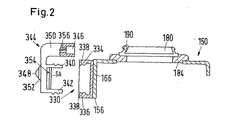
図2におけるリングフレーム150はトラベラ190を有する紡糸リング180とリング保持体184とを保持している。図2に示された紡糸リング180はいわゆる傾斜フランジリング(例えばEP−B−528056号による)として形成されている。しかし本発明では他のタイプのリング(例えば図1に示された一般的なリング横断面を有するリング)を使用することもできる。リングフレームの前面156にはベース部330が適当な手段(図示せず)によって固定されている。このベース部330はリングフレームから突出する2つの壁334、336を有している。この場合、各壁はリングフレームから離れた端部に内隆起部338を備えている。内隆起部338は磁気的なトラベラセンサ346のための保持装置344の結合エレメント340、342とのスナップ結合を形成する。保持装置344はプラスチックから成っている。保持装置344は信号ランプ348の保持枠352をも有している。
The
結合エレメント340、342は信号評価ユニットSAのための固定エレメントとしても役立つ。信号評価ユニットSAは導体354、356を用いて表示器348とセンサ346とに接続されている。したがって保持装置344はベース体330の内部の通路の部分カバーとしても役立つ。
The
EP−A−1074645号によればセンサ346は有利には磁気的なセンサとして構成されている。この構成は技術的評価は高い。しかし、センサエレメントのこの選択は全体費用に重大な影響を及ぼしかつ最終製品(評価電子装置、配線及び操作誘導装置を有する1000+センサ)をリング紡糸機の購入者にとって魅力的な価格で提供することを極めて困難にする。光学的なセンサはより安価に購入することができる。しかし、すでに冒頭で述べたように、トラベラセンサとして反射ヘッドを用いた構成はこれまで出願人が認識するものには存在しない。
According to EP-A-1074645, the
図3にはリング紡糸機の4つの隣り合ったスピンドル116の部分とこのリング紡糸機のリングフレームの支持面113の小さな部分とが示されている。部分117は1つのスピンドル116(紡糸部位)の周囲を隣接したスピンドル116(紡糸部位)の周囲に対してできるだけ遮蔽するいわゆるセパレータである。この図面には5つの紡糸部位のための紡糸リング180の部分も図示されている。
FIG. 3 shows a portion of four
リングフレームの前面側156(左側だけに見える)には、U字形の成形体200が固定されている。このU字形の成形体200はベース部分(図2)同様、通路の1部を形成している。図3においては成形体200はその下にあるリングフレームを示すために左側の端部にて破断されている。固定形式はあまり重要ではない。何故ならばこれから記述するシステムは小さな製作誤差の影響は受けないからである。しかし、成形体の取付けは、成形体200の上方の(自由な)縁部が支持面113と同一平面に位置するように実施したい。成形体200は上方へ開放し、したがって通路はカバーエレメント(センサ保持体)202によって本発明に従って閉鎖されている。この場合、図3には2つのカバーエレメントが部分的に示されている。
A U-shaped molded
各カバーエレメント202は縁条片206で支持面113に支持される1つのカバープレート204と、下方に向って通路内へ突入しかつ成形体200の側壁とスナップ結合を形成する2つの弾性的な固定条片208、210とを有している。固定条片208はストッパ207を有する壁の下部分が形成し、固定条片210はストッパ209を有する壁211の下部分が形成する。ストッパ207、209は成形体200の自由縁部と接触し、支持面113に対するカバープレート204の角度位置を規定する。
Each
各カバープレート204は4つのケーシング212を保持している。図3には左側のカバーエレメント202の1つのケーシング212と右側のカバーエレメント202の3つのケーシング212とが示されている。支持面113に対するケーシングの角度位置もしくは支持面113の上に取付けられた紡糸リングに対するケーシングの角度位置は各カバープレート204の角度位置によって規定される。ケーシング212については図4から7までに基づき以下詳細に記述する。この場合、ケーシング212はすべて同じ構造を有するので、1つのケーシングについての記述は他のすべてのケーシングにも当嵌まる。
Each
各ケーシング212は、2つの側壁214もしくは216(図4)と1つの屋根部分218とを有している。通路200内ではケーシングは底なしで構成されている。つまりケーシングは通路の中空室に向かって完全に開放されている。しかし側壁214、216は縁条片206を越えて突出し、この突出する領域(ケーシングの前方部分において)にて底220(図5)によって結合されているのでケーシング212は外に向かっては閉じられている。「端面側」224、つまりこのケーシングに対応配置された紡糸リング180に向き合ったケーシング壁は、特別に所定の従属請求項の特徴に従って形成されかつこれについては以後詳細に説明する。しかしケーシングの全般的な構成についての記述はとりあえず終了する。
Each
ケーシング212の「背面側」、つまり2つの隣接する機械の間の操作路に向き合ったケーシング壁は湾曲した壁部分226によって形成されている。この壁部分226は図4では、ケーシングの中空室内が見えるように取除かれている。通路内では壁211は1つの懸垂部228と2つのストッパ230とを備えている。これらのエレメントを用いて図8に示したように電子装置基板232はケーシングの端面224に対し所定の位置で取付けられることができる。
The casing wall facing the “back side” of the
電子装置基板232は基板の基本構想においてEP−A−1074645号と関連して記述した基板に類似している。すなわち、電子装置基板232はコンピュータと該コンピュータと電子装置の他の電気的なエレメントとの間の導電路とを備えた保持体を有している。これらのエレメントもしくは導電路自体は本発明にとって重要ではないので、これらは図示していない。しかし基体232は、該基板232が「前方へ」(端面224に向かって)押されると懸垂部228を受容できる開口234を備えている。基板232はストッパ230に当接するまで前方へ押されるようにしたい。開口234と懸垂部228は、基板232がストッパ230に接触すると、開口234と懸垂部228との間に所定のクランプ力が発生するように構成されている。これによりケーシング212内部での基板の位置が与えられる。基板のためのこの固定は本発明にとっては決して重要ではないことを強調しておく。有利には前記固定は基板の位置決めを震動(振動)に対しても保証し、それにも拘らず交換を目的としてケーシングからの基板の取外しを可能にする強度を有している。基板の固定は例えば簡単なストッパ230が基板の縁部分と協働してスナップ結合を形成する弾性的なエレメントに変更されることによって保証される。
The
基板232はEP−A−107645号の基板とは基板232が発光エレメント236(図7)、受光エレメント238(図7及び図8)及び操作を誘導するための信号発生器としての発光ダイオードLEDを備えていることで異っている。図7から判るように発光エレメント236は基板232がストッパ230に接触するとケーシングの前方部分にそのために設けられたポケット240内に受容されるのに対し、受光エレメント238は隣接するポケット242に受容される。ポケット240、242は図4にも示されている。ダイオードLEDは基板の他方の側に取付けられかつ壁部分226に向き合って位置している。
The
マーケットには種々の発光器/受光器エレメントが市販されており、通常は放射する光線もしくは入射する光線を集束するためにそれぞれ固有のレンズを備えている。光透過性の他に特別な要求が端面224に課されない発光器/受光器エレメント対を見い出すこともできる。しかし、この都合のよい状況は、予定されるリング紡糸機における使用に関連した幅の広い問題の観察が示すようにありそうもない。前記幅の広い問題についてはここでは簡単に列挙しておくに留める。
−紡糸リング直径の変化
−リング材料もしくはリング表面質の変化
−トラベラ材料もしくはトラベラ表面質の変化
−トラベラの形もしくはリングに対するトラベラの位置(幾何学的形状)の変化
−トラベラ速度の変化
−紡糸リングとケーシングとの間の最小間隔が重要(紡糸部位の操作もしくは−事情によっては−間隔が小さすぎる場合のトラベラ運動の妨害)
−光線状態の変化(自然光/照明、紡糸部位への遮光…)
−コンポーネントの老朽化
−汚染(繊維屑の堆積、飛散)
又、システムを各使用可能性に個別に適合させる経済的な解決は存在しない。その理由は特に、適合作業はたいてい最終利用者によって実施されなければならず、提供者がマーケット損害を受けることが考えられるからである。したがって端面自体にレンズを設け、このレンズが環境におけるコントロールできない変化に対するフレキシブルな解決を助けることは本発明に不可欠ではないにしてもきわめて有利である。したがって端面の構成についてまず説明する。
There are a variety of emitter / receiver elements on the market, usually with their own lens to focus the emitted or incident light. It is also possible to find emitter / receiver element pairs in which no special requirements are imposed on the
-Change in spinning ring diameter-Change in ring material or surface quality-Change in traveler material or surface quality-Change in traveler shape or traveler position (geometric shape)-Change in traveler speed-Spinning ring The minimum distance between the belt and the casing is important (manipulation of the spinning site or-depending on the circumstances-interference with traveler movement if the distance is too small)
-Change in light state (natural light / lighting, shading to the spinning area ...)
-Aging of components-Contamination (fiber waste accumulation, scattering)
There is also no economical solution to adapt the system to each availability individually. The reason is especially because the conforming work usually has to be carried out by the end user, and it is conceivable that the provider is subject to market damage. It is therefore very advantageous, if not essential to the present invention, to provide a lens on the end face itself and to help the flexible solution to uncontrollable changes in the environment. Therefore, the configuration of the end face will be described first.
発光器236のためにも受光器238のためにも固有の(つまりこれらのエレメントの個々に対応配置された窓240、242(図4と図7)が端面224に設けられている。この窓240、242は少なくとも選択的に透光性である。つまり窓240、242は発光器から放射されかつ受光器によって再び受光しようとする光を通過させる。
所定の定義(Dubbelを参照せよ)によれば光測定技術では可視光線は波長領域λ=380mm(青)から780mm(赤)までとなっている。しかし「光」という概念はこの明細書では可視の電磁的な振動に限定されない。前記概念はここでは人間によって操作される機械の監視に同様に使用できる低エネルギーの光線、特に赤外及び紫外線スペクトルの可視領域に隣接する領域の光線も含まれる。発光器236は図4から7までの構成では有利には赤外領域にて、例えば大き等級850nmから950nmまでの波長領域で放射する。しかしながら、特にレザーが発光エレメントとして選ばれると可視スペクトル領域における光を使用することも可能である。
According to a predetermined definition (see Dubel), in the light measurement technique, the visible light has a wavelength range of λ = 380 mm (blue) to 780 mm (red). However, the concept of “light” is not limited to visible electromagnetic vibration in this specification. The concept here also includes low-energy rays that can be used similarly for monitoring machines operated by humans, especially those in the region adjacent to the visible region of the infrared and ultraviolet spectrum. The
しかし、ここでは「透光性」とは必ずしも絶対的な透明を意味するものではない。受光器が十分な感受性を有している限り、放射されたエネルギの所定の緩和(吸収)も許される。窓の材料はフィルタ作用が生ぜしめられ、選択的に所定の波長(発光器の選択による所定の波長)を通過させるように選ばれることができる。前記材料は例えば赤外領域の外側の波長のためには実質的に不透過であるように選ばれることができる。しかしこの付加的な処置は本発明にとって不可欠ではない。 However, “translucency” here does not necessarily mean absolute transparency. As long as the receiver is sufficiently sensitive, a certain relaxation (absorption) of the emitted energy is also allowed. The window material can be selected to cause filtering and selectively pass a predetermined wavelength (a predetermined wavelength depending on the choice of the light emitter). The material can be chosen to be substantially opaque, for example for wavelengths outside the infrared region. However, this additional treatment is not essential to the present invention.
窓に隣接した壁部分はいずれの場合にも、有利には比較的に低い透光性を有している。これは側壁212、214と屋根218に当嵌まるだけではなく、発光器236と受光器238を受容するポケットの間の分離壁244にも当嵌まる。この処置によって発光器236と受光器238との間の短絡(Crosstalk)が防止される。壁部分の相対的な透光性は材料の選択によって与えられる必要はなく、壁厚さによって決定されることもできる。有利には両方の処置(材料の選択並びに壁厚の選択)を、必要な作用を達成するために利用することができる。ケーシングの前方部分は有利には唯一の材料からかつ合目的的には一体に形成される。有利な材料はプラスチック、例えばポリカーボネートである。窓は0.5から1.5mmの領域の壁厚さを有しているのに対し、比較的に不透光な壁部分は著しく大きな厚さを有していることができる。
In any case, the wall portion adjacent to the window preferably has a relatively low translucency. This not only hits the
ダイオードLEDはこのエレメントが操作誘導装置の1部分として用いられるので、可視光線を放射したい。操作誘導システムの構想は既にEP−A−1074645号(図8から10)に説明されており、ここでは繰返し説明することはしない。このシステムにとっては該当紡糸部位においてミスが発生したことを表示する視的に確認できるようにする信号が重要である。換言すればケーシング212は表示手段としても用いたい。
The diode LED wants to emit visible light because this element is used as part of the operation guidance device. The concept of the operation guidance system has already been described in EP-A-1074645 (FIGS. 8 to 10) and will not be described again here. For this system, a signal that can visually confirm that a mistake has occurred at the spinning site is important. In other words, the
この出願の図3に示された構成によれば信号はダイオードLEDの発光によって発生させられる。したがって背壁226は透性で、しかも可視光線にとって透光性でなければならない。しかし、EP−A−1074645号に記載された誘導構想の枠内ではケーシング212の後方部分全体を透明に構成することは得策ではない。所定の紡糸部位から発せられるアラームもしくは呼び出し信号は当該紡糸部位の周囲の所定の空間領域の内部だけで操作員によって確認可能にしたい。したがってケーシング212の後方部分における側壁214、216はダイオードLEDから発する光線にとってもほぼ不透光である。側壁214、216の形は、特にケーシングの後方部分において、ケーシング内部のダイオードLEDの位置に対して、操作員が紡糸部位の近くの認識域に侵入してはじめて操作員が信号を確認できるように、選択されている。
According to the configuration shown in FIG. 3 of this application, the signal is generated by the light emission of a diode LED. Accordingly, the
次ぎに図9に基づき図3の紡糸部位におけるセンサ装置の幾何学的形状について説明する。基板232、発光器236、受光器238は図9にも示されている。ケーシング212は省略されている。何故ならば窓240、242は透光性であり、これに対し分離壁は不透光性であると仮定されているからである。発光器は製造者により固有のレンズで装備されている。したがってこのエレメントは円錐形に、しかも軸線251を中心として対称に拡散する光線250(破線で図示)を生ぜしめる。受光器238はもちろん光線を発生しないが受光器238に配属されたテストフィールドを有している。このテストフィールドは受光器からの間隔が増すにつれて同様に円錐形に、軸線253を中心として対称的に拡がる。このテストフィールドの円錐形の拡がりは図9では符号252の付けられた破線で示されている。まず軸線251、253は互いに平行に間隔Sをおいて配置されているものと仮定する。図は支持面113に対する軸線251、253の角度位置は示されていない。軸線は支持面113に対し平行に延びているものと仮定する。
Next, the geometric shape of the sensor device at the spinning site in FIG. 3 will be described with reference to FIG. The
紡糸リング180の表面のセグメントは図9においては符号Fで示されている。このセグメントは図9によれば発光器236からも受光器238からも間隔Aをおいて位置している。符号254では紡糸リング180により案内され、矢印Rの方向に移動するトラベラ190の脚部が示されている。トラベラ190は時点T0にて受光器238のテストフィールドに侵入するものと仮定する。この侵入は決して受光器238もしくはセンサ装置の状態における変化を惹起することはない。何故ならばトラベラ190がまずテストフィールド252へ侵入する縁領域RGは発光器236によっては照射されないからである。受光器238のテストフィールド252が発光器236の円錐250とオーバラップする領域UEに脚部254が侵入してはじめてかつ侵入した場合にだけセンサ装置はトラベラ190に反応する(反応することができる)。
The segment of the surface of the
この線図を見た場合にはこの幾何学的な関係を最適化することが想到される。例えば軸線251、253は紡糸リングに接近し、必要とあれば1点でセグメントFにて交差することができる。間隔Sは短絡(発光器から受光器への直接的な伝達)のリスクなしでできるだけ小さく保ちたい。間隔Aも小さく保たれなければならない。
When looking at this diagram, it is conceivable to optimize this geometric relationship. For example, the
しかし、最適化の試みには限界がある。間隔Aは紡糸技術的には小さ過ぎて選ばれてはならない。1つには紡糸リング180に対するケーシング212の接近は糸道の妨害を惹き起し、さらにこの接近は紡糸部位を操作できるようにする必要性によって制約される。したがって10mmよりも小さい間隔Aはいずれにしても問題があり、したがって回避する必要がある。有利には前記間隔は15mmよりも大きいことが有利であり、20mm以上の間隔が合目的的である。しかし間隔Aが増大するに伴って支持面113に対する軸線251、253の角度位置の意味が増大する。間隔Aが大きく選ばれるほど、光線250が紡糸リングの前で面113に当るか又は紡糸リングの上側で糸バルーンの領域に無益に拡散することを回避するためには、前記角度位置は正確に規定される必要がある。
However, there are limitations to optimization attempts. Spacing A is too small for spinning technology and should not be chosen. For one thing, the proximity of the
しかし最適化は多くの場合には失敗する。何故ならば、例えば一般的な紡糸リング(112、図1)が傾斜フランジリング(190、図2)によって置換えられるかかつ/又は与えられた直径の紡糸リングが他の直径の紡糸リングと交換されることでセンサ装置の寿命の間に紡糸部位の状態が変化することを考慮する必要があるからである。紡糸リングの直径はショートステープルファイバを加工するリング紡糸機においては通常35から50mmの領域にて最終利用者により選択される。ロングステープルファイバを加工する機械はより大きなリング直径で働く。 But optimization often fails. This is because, for example, the general spinning ring (112, FIG. 1) is replaced by the inclined flange ring (190, FIG. 2) and / or a given diameter spinning ring is replaced with another diameter spinning ring. This is because it is necessary to consider that the state of the spinning site changes during the lifetime of the sensor device. The diameter of the spinning ring is usually selected by the end user in the region of 35 to 50 mm in a ring spinning machine for processing short staple fibers. Machines that process long staple fibers work with larger ring diameters.
発光器236の放射面は窓240に触れることなく窓240(図7)にできるだけ近く配置したい。発光器236と発光ポケットの内面T1との間には著しい間隔は開かないようにしたい。したがって面T1をわずかな円錐性で構成し、発光器236が窓と接触する前に発光器236が面T1に接触するようにすることが有利である。このような円錐状に延びる面T1は図4において破線で示した円で示されている。
The emission surface of the
受光器238の感光面は有利には発光器236の間隔Aよりもいくらか大きい間隔をオーバラップ領域UEに対して有している。これは小さな間隔a(図7)が受光器の感光面と窓242との間に開けられていることにより保証される。又、これは受光器238が受光ポケットの円錐面T2(図4に概略的に破線で図示)に接触するかかつ/又は受光器238が窓242と接触するフード256(図7)を備えていることでも保証される。
The photosensitive surface of the
光の屈折率を高めるためには窓242かつ/又は窓240はレンズとして構成されることができる。この場合には種々のレンズが可能であり、図10は以下の例を示している:
図10A 外面はコンベックス:内面は一平面内に位置する(プラノーコンベックスレンズ)
図10B 外面コンベックス、内面同様にコンベックス
図10C 外面コンカーブ、内面同様にコンカーブ
図10D 外面コンカーブ、内面は一平面内に位置(プラノーコンカーブレンズ)
この場合、「外面」とはケーシング212の外側にある面である。「内面」はケーシング212の中空室の内部にある。しかし、外面の曲率は両方のレンズ(窓)240、242にとって、つまり発光器のため並びに受光器のために同じである必要はない。
In order to increase the refractive index of light, the
Fig. 10A Convex on the outer surface: the inner surface is in one plane (Plano convex lens)
Fig. 10B Convex as in the outer surface, Convex as in the inner surface Fig. 10C Contour as in the outer surface, Contour as in the inner surface Fig. 10D Contour in the outer surface, the inner surface is located in one plane (Plano Concurve lens)
In this case, the “outer surface” is a surface outside the
前記例は排他的な選択と解されるべきものではなく、選択の可能性の幅を表わすことを目的とするものである。決められた使用に対する最適な形は経験的に求めることができる。この可能性を活用することによって、最大可能な間隔Aはその他の付与されている状態に関し、センサがトラベラ認識閾の下に落ちることなく増大させることができる。別の可能性は1つのレンズをケーシング212に組込むことである。しかしこれはケーシング212にレンズ枠を形成し、このレンズ枠にレンズを取付ける取付け作業を必要とする。これはレンズをケーシング構造自体に統合することで回避されることができる。
The above example should not be construed as an exclusive selection, but is intended to represent the range of possibilities for selection. The optimal form for a given use can be determined empirically. By taking advantage of this possibility, the maximum possible spacing A can be increased for other given conditions without the sensor falling below the traveler recognition threshold. Another possibility is to incorporate one lens into the
有利な実施例においてはケーシング212はいわゆる多機能性の単体ケーシングで形成される。この場合には少なくとも保護及び/又は位置決め及び/又は光集束機能が前記単体ケーシングに統合されるが、しかし、不備な紡糸部位を表示する表示機能も統合されると有利である。前記表示は、糸切れも、誤った回転数を呈するスピンドル(例えば鈍間スピンドル、EP−A−1074645号参照)も表示するように構成することができる。
In an advantageous embodiment, the
有利な製造方法の特徴はプラスチックから成るカバーエレメント202を完全に一体に射出成形法で形成することである。これは、例えば警告もしくは呼出し信号の所定の色を発生させるために背壁226が側壁214、216と屋根部分218とは別の材料から形成されなければならない場合にも可能である。もちろんカバーエレメントの個々の部分を個別に、個々に最適な方法に基づきもしくは個々に最適な(種々の)材料から形成し、これらの部分をエレメント202の製造を目的として接合することも可能である。ケーシング212は個別に製造され、中間片によってカバーエレメントを形成するために結合されることもできる。このようなケーシングは例えば中間片と接着されることができる。
A feature of the advantageous manufacturing method is that the
本発明はリング紡糸機における使用及びリング紡糸機におけるトラベラの検出に限定されるものではない。 The present invention is not limited to use in ring spinning machines and detection of traveler in ring spinning machines.
図3Aには概略的に操作を助成するための光学的な信号を選択的に発信する原理の別の構成が示されている。ケーシング212の場合には光学的な信号が選択的に紡糸部位の近くにおける限られた空間内で発生させられるようになっている。しかし、事情によっては信号を「広空間的」に発生させることが必要である。この場合にはこの空間内には少なくとも1つの別の信号発生器が存在しているので、光源のすぐ近くで信号を発生することはもはや重要ではない。前記要求は「セクションランプ」に当嵌まる。このようなランプは本願の図3には示されていないが、しかしEP−A−1074645号においては図9もしくは図13と関連して明細書に記載されている(「ランプSL」を参照)。センサ保持体の構成の1ユニットとしての「セクション」の構想はEP−A−1052314号に記載されている。したがってEP−A−1052314号もEP−A−1074645号も本願明細書に統合された部分を成すものである。
FIG. 3A schematically shows another configuration of the principle of selectively transmitting an optical signal for assisting the operation. In the case of the
EP−A−1074645号に記述した構想によれば所定のセクションのセクションランプは、このセクション内の少なくとも1つの紡糸部位が不備であると、例えば糸切れを有していると点灯する。当該セクションのセクションランプは、当該セクションが機械中央部に位置していても、できるだけ機械端部から良好に認識可能でなければならない。したがって光源の光量はできるだけ効果的に優先方向で活用されるようにしたい。この課題の解決は図3Aに示されている。 According to the concept described in EP-A-1074645, the section lamp of a given section lights up if at least one spinning site in this section is defective, for example if it has a thread break. The section lamps of the section should be recognizable as well as possible from the machine end, even if the section is located in the middle of the machine. Therefore, it is desirable to use the light quantity of the light source in the priority direction as effectively as possible. A solution to this problem is shown in FIG. 3A.
図3Aにおいては符号280は成形体200−図3を参照−の、内面1Fと外面AFとを有する自由な前壁を示している。各セクションのために成形体もしくは各成形体部分の前壁280は、貫通した円形の孔281を備えている。この孔281はボタン状の部体282を受容している。成形体の内部には発光ダイオード283を有するプレートPが存在しており、この発光ダイオード283はプレートPにおける適当な導体統合によって点灯励起される。このダイオード283は各セクションランプのための光源を成す。
In FIG. 3A,
部体282は円板状のヘッド部284と円筒状のステム285とから成っている。部体282は有利には一体に、しかも有利な実施例では透光性のプラスチックから形成されている。ステム285はヘッド部284が壁280の外面AFに当たるまで孔281を通して押込まれる。この結果、ステム285の端面286はダイオード283の近くに位置し、ダイオードから発する全光線をステム285内へ導く。ステム285の円筒形の外面は内方へ鏡として作用し、端面286を介して侵入する光線はステムの長手方向にヘッド部284まで伝送される。光はヘッド282を、ヘッド部の円筒面289を介して後にし、ひいては機械長手方向にはよく見えるが、ステム285の長手方向にはほとんど見ることはできない。
The
本発明は図3Aに示された構成の詳細に限定されるものではない。部体282の幾何学的形状は所望の作用を達成するために材料の屈折率に適合させられることができる。
The present invention is not limited to the details of the configuration shown in FIG. 3A. The geometry of the
したがってこの構想においてはケーシング部分が光学的な表示のために役立つ。このケーシング部分は、第1の方向(例えば細長い部分の長手方向)の光透過性のために形成された透光性の部分(例えばステム285)を有している。この方向は光を第1の方向から第2の優先的な方向に屈折できる反射面(円錐面287)へ向けられている。 Thus, in this concept, the casing part serves for optical display. The casing portion has a translucent portion (eg, stem 285) formed for light transmissivity in a first direction (eg, the longitudinal direction of the elongated portion). This direction is directed to a reflective surface (conical surface 287) that can refract light from a first direction to a second preferential direction.
110 リングフレーム
111 支え部
112 紡糸リング
113 支持面
114 保持装置
116 スピンドル
118 コップ
120 レール
122 保持体
124 リング
125 孔
126 透し孔
128 ストライプ
190 トラベラ
200 成形体
202 カバーエレメント
204 カバープレート
206 縁部条片
207 ストッパ
208 固定条片
209 ストッパ
210 固定条片
211 壁
212 ケーシング
214 側壁
216 側壁
218 屋根
220 底
224 端面
226 壁部分
228 懸垂部
230 ストッパ
232 電子装置基板
234 開口
236 発光器
238 受光器
240 ポケット
242 ポケット
250 光線
251 軸線
252 テストフィールド
253 軸線
254 脚部
256 フード
280 前壁
281 孔
282 部体
283 ダイオード
284 ヘッド部
285 ステム
286 端面
287 凹部
289 面
DESCRIPTION OF
Claims (33)
Applications Claiming Priority (2)
| Application Number | Priority Date | Filing Date | Title |
|---|---|---|---|
| CH13902002 | 2002-08-13 | ||
| PCT/CH2003/000543 WO2004015179A1 (en) | 2002-08-13 | 2003-08-12 | Sensor system for a ring spinning machine |
Publications (1)
| Publication Number | Publication Date |
|---|---|
| JP2005535794A true JP2005535794A (en) | 2005-11-24 |
Family
ID=31501646
Family Applications (1)
| Application Number | Title | Priority Date | Filing Date |
|---|---|---|---|
| JP2004526569A Pending JP2005535794A (en) | 2002-08-13 | 2003-08-12 | Sensor device for ring spinning machine |
Country Status (6)
| Country | Link |
|---|---|
| US (1) | US20060232778A1 (en) |
| EP (1) | EP1540053B1 (en) |
| JP (1) | JP2005535794A (en) |
| CN (1) | CN1688756B (en) |
| AU (1) | AU2003249831A1 (en) |
| WO (1) | WO2004015179A1 (en) |
Cited By (2)
| Publication number | Priority date | Publication date | Assignee | Title |
|---|---|---|---|---|
| JP2015021216A (en) * | 2013-07-17 | 2015-02-02 | ザウラー ジャーマニー ゲゼルシャフト ミット ベシュレンクテル ハフツング ウント コンパニー コマンディートゲゼルシャフトSaurer Germany GmbH & Co. KG | Ring spinning machine including sensor for detecting movement of ring traveler |
| EP3388564A1 (en) | 2017-04-11 | 2018-10-17 | Kabushiki Kaisha Toyota Jidoshokki | Ring spinning machine comprising a doffing failure detection device |
Families Citing this family (7)
| Publication number | Priority date | Publication date | Assignee | Title |
|---|---|---|---|---|
| US7918387B2 (en) * | 2008-11-04 | 2011-04-05 | Jerome Kahn | Thread identification system |
| US20100224112A1 (en) * | 2009-03-05 | 2010-09-09 | Jerome Kahn | Automatic sizing of embroidery |
| CN102534896B (en) * | 2012-01-13 | 2014-06-04 | 顾金华 | Yarn twisting broken end detecting method for spinning machine |
| JP5796558B2 (en) * | 2012-09-05 | 2015-10-21 | 株式会社豊田自動織機 | Spinning yarn detection device |
| CN102995188A (en) * | 2012-11-30 | 2013-03-27 | 宁波瑞能电子科技有限公司 | Broken yarn detection mechanism |
| DE102015002528A1 (en) * | 2015-03-02 | 2016-09-08 | Detlef Görgens | Textile machine with trusses made of mineral casting |
| CZ201888A3 (en) * | 2018-02-22 | 2019-09-04 | Rieter Cz S.R.O. | Method of controlling an optical element at a workstation of a textile machine, in particular a yarn manufacturing machine and a textile machine |
Citations (23)
| Publication number | Priority date | Publication date | Assignee | Title |
|---|---|---|---|---|
| JPS4840572B1 (en) * | 1968-10-14 | 1973-12-01 | ||
| JPS4974972A (en) * | 1972-10-16 | 1974-07-19 | ||
| JPS5036739A (en) * | 1973-07-06 | 1975-04-07 | ||
| JPS534561A (en) * | 1972-10-16 | 1978-01-17 | Loepfe Ag Geb | Photooelectric device |
| US4300342A (en) * | 1979-12-05 | 1981-11-17 | El-Trol, Inc. | Roving frame stop apparatus |
| CH658080A5 (en) * | 1982-12-09 | 1986-10-15 | Witschi & Co | Apparatus for the optoelectronic monitoring of an individual roving between the drafting unit and spindle of a flyer |
| JPS62117833A (en) * | 1985-10-18 | 1987-05-29 | チンザ−・テクステイルマシイネン・ゲゼルシヤフト・ミト・ベシユレンクテル・ハフツング | Fine spinning machine |
| JPS62117834A (en) * | 1985-10-18 | 1987-05-29 | チンザ−・テクステイルマシイネン・ゲゼルシヤフト・ミト・ベシユレンクテル・ハフツング | Fine spinning machine |
| DE3635140A1 (en) * | 1986-10-15 | 1988-04-21 | Zinser Textilmaschinen Gmbh | Optical scanning device for detecting a feed bobbin running empty in a spinning or twisting machine |
| DE3828471A1 (en) * | 1988-08-22 | 1990-03-01 | Zinser Textilmaschinen Gmbh | Method and device for monitoring the rotation of ring travellers on a ring-spinning or ring-twisting machine |
| JPH02277830A (en) * | 1989-01-10 | 1990-11-14 | Mas Fab Rieter Ag | Method and apparatus for block exchange of roving bobbin in ring spinning frame |
| JPH038719U (en) * | 1989-06-13 | 1991-01-28 | ||
| EP0480898A1 (en) * | 1990-10-04 | 1992-04-15 | Barco Automation, Naamloze Vennootschap | Measuring process for monitoring and controlling ring and traveller spinning or twisting machines, and apparatus for measuring the rotational speed of the yarn driven by the traveller |
| JPH06278946A (en) * | 1993-03-26 | 1994-10-04 | Oohiro:Kk | Optical type broken thread detecting device |
| JPH07109625A (en) * | 1993-10-06 | 1995-04-25 | Howa Mach Ltd | Detector for roving breakage of roving frame |
| JPH09111556A (en) * | 1995-10-16 | 1997-04-28 | Toyota Autom Loom Works Ltd | Attaching apparatus of yarn breakage sensor in spinning machinery and yarn breakage sensor |
| JPH09229848A (en) * | 1996-02-27 | 1997-09-05 | Asahi Chem Ind Co Ltd | Purging device and abnormality detection apparatus provided with this device |
| JPH09279426A (en) * | 1996-04-15 | 1997-10-28 | Toyota Autom Loom Works Ltd | End breakage sensor for spinning machine |
| EP1052314A1 (en) * | 1999-05-06 | 2000-11-15 | Maschinenfabrik Rieter Ag | Sensor system for a ring spinning machine |
| JP2000335829A (en) * | 1999-05-28 | 2000-12-05 | Toray Eng Co Ltd | Filament yarn detecting device |
| EP1074645A1 (en) * | 1999-06-26 | 2001-02-07 | Maschinenfabrik Rieter Ag | Sensor system for ring spinning machines |
| JP2001226840A (en) * | 2000-01-28 | 2001-08-21 | Truetzschler Gmbh & Co Kg | Apparatus for detecting movement and/or existence of fiber sliver |
| JP2002071553A (en) * | 2000-08-28 | 2002-03-08 | Sunx Ltd | Optical fiber sensor |
Family Cites Families (4)
| Publication number | Priority date | Publication date | Assignee | Title |
|---|---|---|---|---|
| DE2334389A1 (en) * | 1973-07-06 | 1975-01-23 | Leuze Electronic Kg | ARRANGEMENT ON PROCESSING MACHINES OF FAEDS AND FIBERS TO INFLUENCE THE DELIVERY SPEED |
| US5636893A (en) * | 1995-04-17 | 1997-06-10 | Wheatley; Donald E. | Folding hard panel tonneau cover with rail attachment |
| EP0924324B1 (en) * | 1997-12-17 | 2002-09-04 | Zellweger Luwa Ag | Apparatus for the supervision of yarns on ring spinning machines |
| US6076881A (en) * | 1998-10-07 | 2000-06-20 | Design Automotive Group, Inc. | Flip hatch tonneau cover |
-
2003
- 2003-08-12 CN CN038241633A patent/CN1688756B/en not_active Expired - Fee Related
- 2003-08-12 US US10/524,522 patent/US20060232778A1/en not_active Abandoned
- 2003-08-12 JP JP2004526569A patent/JP2005535794A/en active Pending
- 2003-08-12 AU AU2003249831A patent/AU2003249831A1/en not_active Abandoned
- 2003-08-12 WO PCT/CH2003/000543 patent/WO2004015179A1/en active Application Filing
- 2003-08-12 EP EP03783893.5A patent/EP1540053B1/en not_active Expired - Lifetime
Patent Citations (23)
| Publication number | Priority date | Publication date | Assignee | Title |
|---|---|---|---|---|
| JPS4840572B1 (en) * | 1968-10-14 | 1973-12-01 | ||
| JPS4974972A (en) * | 1972-10-16 | 1974-07-19 | ||
| JPS534561A (en) * | 1972-10-16 | 1978-01-17 | Loepfe Ag Geb | Photooelectric device |
| JPS5036739A (en) * | 1973-07-06 | 1975-04-07 | ||
| US4300342A (en) * | 1979-12-05 | 1981-11-17 | El-Trol, Inc. | Roving frame stop apparatus |
| CH658080A5 (en) * | 1982-12-09 | 1986-10-15 | Witschi & Co | Apparatus for the optoelectronic monitoring of an individual roving between the drafting unit and spindle of a flyer |
| JPS62117833A (en) * | 1985-10-18 | 1987-05-29 | チンザ−・テクステイルマシイネン・ゲゼルシヤフト・ミト・ベシユレンクテル・ハフツング | Fine spinning machine |
| JPS62117834A (en) * | 1985-10-18 | 1987-05-29 | チンザ−・テクステイルマシイネン・ゲゼルシヤフト・ミト・ベシユレンクテル・ハフツング | Fine spinning machine |
| DE3635140A1 (en) * | 1986-10-15 | 1988-04-21 | Zinser Textilmaschinen Gmbh | Optical scanning device for detecting a feed bobbin running empty in a spinning or twisting machine |
| DE3828471A1 (en) * | 1988-08-22 | 1990-03-01 | Zinser Textilmaschinen Gmbh | Method and device for monitoring the rotation of ring travellers on a ring-spinning or ring-twisting machine |
| JPH02277830A (en) * | 1989-01-10 | 1990-11-14 | Mas Fab Rieter Ag | Method and apparatus for block exchange of roving bobbin in ring spinning frame |
| JPH038719U (en) * | 1989-06-13 | 1991-01-28 | ||
| EP0480898A1 (en) * | 1990-10-04 | 1992-04-15 | Barco Automation, Naamloze Vennootschap | Measuring process for monitoring and controlling ring and traveller spinning or twisting machines, and apparatus for measuring the rotational speed of the yarn driven by the traveller |
| JPH06278946A (en) * | 1993-03-26 | 1994-10-04 | Oohiro:Kk | Optical type broken thread detecting device |
| JPH07109625A (en) * | 1993-10-06 | 1995-04-25 | Howa Mach Ltd | Detector for roving breakage of roving frame |
| JPH09111556A (en) * | 1995-10-16 | 1997-04-28 | Toyota Autom Loom Works Ltd | Attaching apparatus of yarn breakage sensor in spinning machinery and yarn breakage sensor |
| JPH09229848A (en) * | 1996-02-27 | 1997-09-05 | Asahi Chem Ind Co Ltd | Purging device and abnormality detection apparatus provided with this device |
| JPH09279426A (en) * | 1996-04-15 | 1997-10-28 | Toyota Autom Loom Works Ltd | End breakage sensor for spinning machine |
| EP1052314A1 (en) * | 1999-05-06 | 2000-11-15 | Maschinenfabrik Rieter Ag | Sensor system for a ring spinning machine |
| JP2000335829A (en) * | 1999-05-28 | 2000-12-05 | Toray Eng Co Ltd | Filament yarn detecting device |
| EP1074645A1 (en) * | 1999-06-26 | 2001-02-07 | Maschinenfabrik Rieter Ag | Sensor system for ring spinning machines |
| JP2001226840A (en) * | 2000-01-28 | 2001-08-21 | Truetzschler Gmbh & Co Kg | Apparatus for detecting movement and/or existence of fiber sliver |
| JP2002071553A (en) * | 2000-08-28 | 2002-03-08 | Sunx Ltd | Optical fiber sensor |
Cited By (2)
| Publication number | Priority date | Publication date | Assignee | Title |
|---|---|---|---|---|
| JP2015021216A (en) * | 2013-07-17 | 2015-02-02 | ザウラー ジャーマニー ゲゼルシャフト ミット ベシュレンクテル ハフツング ウント コンパニー コマンディートゲゼルシャフトSaurer Germany GmbH & Co. KG | Ring spinning machine including sensor for detecting movement of ring traveler |
| EP3388564A1 (en) | 2017-04-11 | 2018-10-17 | Kabushiki Kaisha Toyota Jidoshokki | Ring spinning machine comprising a doffing failure detection device |
Also Published As
| Publication number | Publication date |
|---|---|
| CN1688756B (en) | 2010-05-12 |
| AU2003249831A1 (en) | 2004-02-25 |
| US20060232778A1 (en) | 2006-10-19 |
| WO2004015179A1 (en) | 2004-02-19 |
| EP1540053A1 (en) | 2005-06-15 |
| CN1688756A (en) | 2005-10-26 |
| EP1540053B1 (en) | 2014-04-30 |
Similar Documents
| Publication | Publication Date | Title |
|---|---|---|
| JP5135140B2 (en) | Flame detector | |
| JP6753653B2 (en) | Proximity sensor and electronic devices using it | |
| US6871988B2 (en) | Lamp for vehicles | |
| KR101640989B1 (en) | Limited area reflective optical sensor and electronic device | |
| JP2005535794A (en) | Sensor device for ring spinning machine | |
| JP5096276B2 (en) | Flame detection unit | |
| JP2023093661A (en) | fire detector | |
| TWI681423B (en) | keyboard | |
| KR100205690B1 (en) | Thread feeder | |
| JP3741509B2 (en) | Tube liquid sensor | |
| JP2005521226A (en) | Device for photoelectrically detecting the switching position of the switching means | |
| JP6323057B2 (en) | Photoelectric sensor | |
| US8096473B2 (en) | Optical reader for reading identification codes on optical discs | |
| JP5128232B2 (en) | Reflective photoelectric sensor | |
| JP6338378B2 (en) | Optical fiber head, optical sensor | |
| JP7397266B2 (en) | Detection device with visual field obstruction monitoring function | |
| JP5135141B2 (en) | Flame detector | |
| JP3212485B2 (en) | Medium detection device | |
| JPH10255614A (en) | Photoelectric sensor, optical holder, and optical holder module | |
| JP7341819B2 (en) | flame detector | |
| JPH06251669A (en) | Reflection type photoelectric switch | |
| EP3825602B1 (en) | Automotive lighting and/or signaling device | |
| JPH0114001Y2 (en) | ||
| JP2019102294A (en) | Vehicular lighting fixture | |
| KR970021598A (en) | Lock with light source |
Legal Events
| Date | Code | Title | Description |
|---|---|---|---|
| A621 | Written request for application examination |
Free format text: JAPANESE INTERMEDIATE CODE: A621 Effective date: 20060630 |
|
| A131 | Notification of reasons for refusal |
Free format text: JAPANESE INTERMEDIATE CODE: A131 Effective date: 20090318 |
|
| A601 | Written request for extension of time |
Free format text: JAPANESE INTERMEDIATE CODE: A601 Effective date: 20090618 |
|
| A602 | Written permission of extension of time |
Free format text: JAPANESE INTERMEDIATE CODE: A602 Effective date: 20090625 |
|
| A601 | Written request for extension of time |
Free format text: JAPANESE INTERMEDIATE CODE: A601 Effective date: 20090721 |
|
| A602 | Written permission of extension of time |
Free format text: JAPANESE INTERMEDIATE CODE: A602 Effective date: 20090728 |
|
| A601 | Written request for extension of time |
Free format text: JAPANESE INTERMEDIATE CODE: A601 Effective date: 20090818 |
|
| A602 | Written permission of extension of time |
Free format text: JAPANESE INTERMEDIATE CODE: A602 Effective date: 20090825 |
|
| A521 | Written amendment |
Free format text: JAPANESE INTERMEDIATE CODE: A523 Effective date: 20090918 |
|
| A131 | Notification of reasons for refusal |
Free format text: JAPANESE INTERMEDIATE CODE: A131 Effective date: 20091204 |
|
| A601 | Written request for extension of time |
Free format text: JAPANESE INTERMEDIATE CODE: A601 Effective date: 20100226 |
|
| A602 | Written permission of extension of time |
Free format text: JAPANESE INTERMEDIATE CODE: A602 Effective date: 20100305 |
|
| A02 | Decision of refusal |
Free format text: JAPANESE INTERMEDIATE CODE: A02 Effective date: 20100603 |