JP2005533305A - Synchronous multichannel universal serial bus - Google Patents
Synchronous multichannel universal serial bus Download PDFInfo
- Publication number
- JP2005533305A JP2005533305A JP2004520197A JP2004520197A JP2005533305A JP 2005533305 A JP2005533305 A JP 2005533305A JP 2004520197 A JP2004520197 A JP 2004520197A JP 2004520197 A JP2004520197 A JP 2004520197A JP 2005533305 A JP2005533305 A JP 2005533305A
- Authority
- JP
- Japan
- Prior art keywords
- usb
- signal
- devices
- token
- usb device
- Prior art date
- Legal status (The legal status is an assumption and is not a legal conclusion. Google has not performed a legal analysis and makes no representation as to the accuracy of the status listed.)
- Pending
Links
Images


Classifications
-
- G—PHYSICS
- G06—COMPUTING; CALCULATING OR COUNTING
- G06F—ELECTRIC DIGITAL DATA PROCESSING
- G06F13/00—Interconnection of, or transfer of information or other signals between, memories, input/output devices or central processing units
- G06F13/38—Information transfer, e.g. on bus
- G06F13/42—Bus transfer protocol, e.g. handshake; Synchronisation
- G06F13/4265—Bus transfer protocol, e.g. handshake; Synchronisation on a point to point bus
- G06F13/4278—Bus transfer protocol, e.g. handshake; Synchronisation on a point to point bus using an embedded synchronisation
-
- G—PHYSICS
- G06—COMPUTING; CALCULATING OR COUNTING
- G06F—ELECTRIC DIGITAL DATA PROCESSING
- G06F13/00—Interconnection of, or transfer of information or other signals between, memories, input/output devices or central processing units
- G06F13/38—Information transfer, e.g. on bus
- G06F13/42—Bus transfer protocol, e.g. handshake; Synchronisation
- G06F13/4247—Bus transfer protocol, e.g. handshake; Synchronisation on a daisy chain bus
- G06F13/426—Bus transfer protocol, e.g. handshake; Synchronisation on a daisy chain bus using an embedded synchronisation, e.g. Firewire bus, Fibre Channel bus, SSA bus
-
- H—ELECTRICITY
- H04—ELECTRIC COMMUNICATION TECHNIQUE
- H04J—MULTIPLEX COMMUNICATION
- H04J3/00—Time-division multiplex systems
- H04J3/02—Details
- H04J3/06—Synchronising arrangements
- H04J3/0635—Clock or time synchronisation in a network
- H04J3/0682—Clock or time synchronisation in a network by delay compensation, e.g. by compensation of propagation delay or variations thereof, by ranging
-
- H—ELECTRICITY
- H04—ELECTRIC COMMUNICATION TECHNIQUE
- H04L—TRANSMISSION OF DIGITAL INFORMATION, e.g. TELEGRAPHIC COMMUNICATION
- H04L7/00—Arrangements for synchronising receiver with transmitter
- H04L7/0008—Synchronisation information channels, e.g. clock distribution lines
Abstract
Description
本発明は、ユニバーサルシリアルバス(USB)デバイスを同期させる方法及び装置に関し、特に、USBホストに接続されたUSBデバイス同士を任意の精度で互いに同期させることに適用されるが、それのみには限定されない。 The present invention relates to a method and apparatus for synchronizing universal serial bus (USB) devices, and in particular, is applicable to synchronizing USB devices connected to a USB host with each other with arbitrary accuracy, but is not limited thereto. Not.
USB仕様は、オープンアーキテクチャの下で、製造元が異なるデバイスの相互運用を推進することを意図したものである。USBデータは、差動信号方式(すなわち、2本の電線で情報を転送する方式)を用いて、それら2本の電線の信号レベルの差の形でエンコードされる。USB仕様は、ポータブル環境、デスクトップ環境、及びホーム環境にまたがるPCアーキテクチャの拡張として企画されている。 The USB specification is intended to promote interoperability of devices of different manufacturers under an open architecture. The USB data is encoded in the form of a difference in signal level between the two wires using a differential signal method (that is, a method of transferring information using the two wires). The USB specification is being planned as an extension of the PC architecture across portable, desktop and home environments.
たとえば、従来技術の一例として、デジタル制御されるトランスデューサ12を含むUSBデバイス10の概略図を図1に示す。デバイス10は、バスコントローラ14、デジタルI/Oバス転送回路16、及びマイクロプロセッサ18と、トリガ信号及びクロック信号を含む同期情報をトランスデューサ12に渡す同期チャネル20を含む。
For example, as an example of the prior art, a schematic diagram of a
デバイス10は、バスコントローラ14によって、USB信号及び同期信号を収容しているデジタルバス22に接続されている。
The
USB仕様は、すべてのデバイスが異なることを暗黙のうちに想定している。このことは、多種多様な製造元のデバイスを接続するという、当初の意図どおりの環境には当てはまるが、ほぼ同等の性質を有する複数のデバイスを同期動作させるための仕様を必要とする、当初の意図どおりでない環境(ある共通の製造業環境や実験室環境など)も存在する。USB仕様は、そうした課題への対応が不十分である。そのような環境は、一般に、試験、測定、監視などを実施する環境であり、そこでは、仕様より高い精度でデバイスを同期させることが必要になる場合がある。USB仕様で可能な同期は、すべてのデバイスに1kHzクロック信号を供給することによるデバイス間同期だけである。しかしながら、多くの実験室環境や製造業環境では、MHzレベル以上の周波数での同期が必要とされる。 The USB specification implicitly assumes that all devices are different. This applies to the original intended environment of connecting devices from a wide variety of manufacturers, but the original intention that requires specifications to synchronize multiple devices with similar properties. There are some unconventional environments (such as a common manufacturing environment or laboratory environment). The USB specification is insufficient in dealing with such problems. Such an environment is typically an environment in which testing, measurement, monitoring, etc. is performed, where it may be necessary to synchronize the device with higher accuracy than specifications. The only synchronization possible with the USB specification is inter-device synchronization by supplying a 1 kHz clock signal to all devices. However, many laboratory and manufacturing environments require synchronization at frequencies above the MHz level.
図2に示すUSBはティアードスタートポロジ24を用いており、ハブ26がUSBデバイス28の接続点を提供している。USBホストコントローラ30にはルートハブが含まれ、これがシステム内のすべてのUSBポートの起点になっている。このルートハブには、USB対応デバイスや追加ハブを接続できるUSBポートがいくつか設けられている。
The USB shown in FIG. 2 uses a
これらのどのポートにも、さらにハブ(USB複合デバイス32など)を接続でき、それによって、さらなるUSBデバイス34のための接続点(ポート経由)が追加される。このように、USBを用いると、最大127個のデバイス(ハブを含む)を接続できる。ただし、どのデバイスも階層の深さが5まででなければならない。
Any of these ports can be further connected to a hub (such as a USB composite device 32), thereby adding an attachment point (via a port) for
ホスト内のルートハブは、Start of Frame(フレーム開始)(SOF)信号パケットを1.0ミリ秒おきにすべてのデバイスに送信する(2つのSOFパケットの時間間隔を1フレームと呼ぶ)。USBトポロジに固有の電気的遅延のため、各モジュールがこのSOFパケットを受信するのは同時ではない。このトポロジは、ホストコントローラに直接接続されているデバイスから、5階層下がったところにあるデバイスまでの間で、同じ信号を受信するのにかなりの時間遅延(仕様では最大380ナノ秒)がありうることを示している。このことは、MHzレベル以上でデバイスを同期しなければならない場合には、深刻な制約となる。 The root hub in the host sends a Start of Frame (SOF) signal packet to all devices every 1.0 milliseconds (the time interval between two SOF packets is called one frame). Due to the electrical delay inherent in the USB topology, each module receives this SOF packet at the same time. This topology can have significant time delay (up to 380 nanoseconds in the specification) to receive the same signal from the device directly connected to the host controller to the device that is five layers down. It is shown that. This is a serious limitation when devices must be synchronized above the MHz level.
現時点では、USBホストとUSBデバイスの間の同期は、2タイプのUSB転送、すなわち、インタラプト転送とアイソクロナス転送によって可能である。インタラプト転送では、125マイクロ秒の最短周期でのデバイスのポーリング頻度が保証され、アイソクロナス転送では、一定の転送レートが保証される。いずれの方法でも、デバイスとホストの間で同期用のトラフィックを発生させる必要があり、したがって、同期の精度を高くするほど、多くの帯域幅を確保する必要がある。このことは、最大数のデバイスを接続する前に、使用可能なUSB帯域幅を使い切ってしまうおそれがあることを意味する。この方法はさらに、ソフトウェアを用いて127個のデバイスをホストに同期させたままにすることの多大な計算負荷をホストにかけ、それにもかかわらず、個々のデバイスが別々のプロセスを担当しているホストに関しては、デバイス間の同期を維持することに対応できない。 At present, synchronization between a USB host and a USB device is possible by two types of USB transfer, namely interrupt transfer and isochronous transfer. In interrupt transfer, the device polling frequency is assured in the shortest cycle of 125 microseconds, and in isochronous transfer, a constant transfer rate is guaranteed. In either method, it is necessary to generate traffic for synchronization between the device and the host. Therefore, the higher the synchronization accuracy, the more bandwidth needs to be secured. This means that the available USB bandwidth may be used up before connecting the maximum number of devices. This method also places a heavy computational burden on the software to keep 127 devices synchronized to the host, nevertheless a host where each device is responsible for a separate process. With respect to, it cannot cope with maintaining synchronization between devices.
ある種の物理トランスデューサ(レーザダイオードや光検出器など)を含むデバイスは、クロック情報及びトリガ情報を必要とする場合がある。そのようなデバイス(たとえば、1MHzの変調光出力を有するレーザダイオード)は、クロック信号を用いて、一定間隔又は一定周波数でトランスデューサ機能を実行することができる。トリガ信号は、通常、設定された時刻に動作を開始又は終了させるために用いられる。レーザダイオードの例では、トリガ信号を用いて、変調光出力のオン/オフを切り替えることができる。 Devices that include certain types of physical transducers (such as laser diodes and photodetectors) may require clock information and trigger information. Such a device (eg, a laser diode with a 1 MHz modulated light output) can perform a transducer function at regular intervals or at a constant frequency using a clock signal. The trigger signal is usually used to start or end the operation at a set time. In the example of the laser diode, the modulated light output can be turned on / off using a trigger signal.
このようなクロック信号(情報)及びトリガ信号(情報)(以下、「同期情報」と呼ぶ)がすべてのデバイスに共通であり、同時に供給されていれば、これらの信号を用いて、多数の多種多様なデバイス同士を互いに同期させることができる。ここでの「共通」及び「同時」は、これらの信号のデバイス間での時間変動が指定量δtより少ないことを意味する。レーザダイオードの例では、それによって、多数の多種多様なレーザダイオードがそれぞれの光出力を1つの周波数で変調することが可能になる。その結果、すべてのデバイスの変調周波数が同じになり、それらの波形が同相になる。現行のUSB仕様(すなわち、2.0)では、最大0.35マイクロ秒のδtの遅延が許容される。この遅延は、周波数1MHzすなわち周期1.0マイクロ秒の信号の場合には、ほぼ半周期に相当する。したがって、この信号を、定常的な用途での同期信号として仕様通りに使用することはできない。 If such a clock signal (information) and trigger signal (information) (hereinafter referred to as “synchronization information”) are common to all devices and are supplied at the same time, a large number of various signals can be obtained using these signals. Various devices can be synchronized with each other. Here, “common” and “simultaneous” mean that the time variation of these signals between devices is smaller than the specified amount δt. In the laser diode example, it allows a large number of different laser diodes to modulate their light output at one frequency. As a result, all devices have the same modulation frequency and their waveforms are in phase. The current USB specification (ie 2.0) allows a delay of δt up to 0.35 microseconds. This delay corresponds to approximately a half period in the case of a signal having a frequency of 1 MHz, that is, a period of 1.0 microsecond. Therefore, this signal cannot be used as specified as a synchronization signal in a stationary application.
ハブやUSBコントローラチップのようなデバイスは、USBプロトコルをデコードするために、ある程度の位相ロックをかけるのが一般的である。USBプロトコルのSYNCパターンの目的は、他の電子回路がロックすべき同期パターンを提供することである。ただし、これは、MHzビットストリームを解釈するのに十分な精度でデバイスをUSBビットストリームに同期させることを想定したものであって、多くの試験器や測定器で必要とされる精度で別々の2つのデバイスを互いに同期させることは想定されていない。USB仕様は、デバイス間同期の取り扱いに関する限り、USB−CDオーディオストリームを、一対のUSBスピーカからの出力に十分な程度に同期させることを主眼としている。そのような装置の要求はkHzレベルであり、これに対してUSBは理想的な条件を提供する。しかしながら、100対のUSBスピーカを同期させるという、起こりうる課題には、USB仕様は対応できない。 Devices such as hubs and USB controller chips typically apply some phase lock to decode the USB protocol. The purpose of the USB protocol SYNC pattern is to provide a synchronization pattern that other electronic circuits should lock. However, this assumes that the device is synchronized to the USB bitstream with sufficient accuracy to interpret the MHz bitstream, and is separate with the accuracy required by many testers and instruments. It is not assumed that the two devices are synchronized with each other. As far as the handling of the inter-device synchronization is concerned, the USB specification is mainly intended to synchronize the USB-CD audio stream to a level sufficient for output from a pair of USB speakers. The requirement for such devices is the kHz level, whereas USB provides ideal conditions. However, the USB specification cannot cope with a possible problem of synchronizing 100 pairs of USB speakers.
米国特許第6343364号(Leydierら)では、USBトラフィックへの周波数ロックの例が開示されている。これは、スマートカードリーダを対象としたものである。この特許は、USB SYNC及びパケットIDストリームと比較されるローカルの自走クロックを教示しており、その周期は、この周波数と一致するように更新される。その結果、定格周波数1.5MHzのローカルクロックが得られる。これにより、スマートカード情報をホストPCに読み込むのに十分な程度の同期が得られる。この方法はスマートカードリーダを対象としており、デバイス間同期は対象外である。さらに、1kHzの周波数ロック(又は安定性の向上)についても、高精度の位相制御についても開示されていない。 US Pat. No. 6,343,364 (Leydier et al.) Discloses an example of frequency locking to USB traffic. This is intended for smart card readers. This patent teaches a local free-running clock that is compared to a USB SYNC and packet ID stream, whose period is updated to match this frequency. As a result, a local clock with a rated frequency of 1.5 MHz is obtained. This provides a degree of synchronization sufficient to read smart card information into the host PC. This method is intended for smart card readers and does not include inter-device synchronization. Furthermore, neither 1 kHz frequency lock (or stability improvement) nor high precision phase control is disclosed.
米国特許第6012115号(Chambersら)は、USBフレーム開始(SOF)の周期性とタイミング調節のための番号付けに関するものである。米国特許第6012115号の要約書で説明されているように、開示されている発明は、USBホストコントローラからそれに接続されている周辺デバイスに送信されるフレーム開始パルスを用いることにより、リアルタイム周辺デバイス内で所定のイベントが発生する瞬間をコンピュータシステムが正確に特定することを可能にする。 US 6012115 (Chambers et al.) Relates to USB frame start (SOF) periodicity and numbering for timing adjustment. As described in the abstract of US Pat. No. 6012115, the disclosed invention uses a frame start pulse transmitted from a USB host controller to a peripheral device connected to it, in a real-time peripheral device. Allows the computer system to accurately identify the moment when the predetermined event occurs.
米国特許第6092210号(Larkyら)では、データ転送の目的で2つのUSBホストを接続するために、USB対USB接続デバイスを用いて、ローカルデバイスクロックを両USBホストのデータストリームに同期させる方法が開示されている。ローカルクロックを同期させるために位相ロックループを用い、データ損失の発生を抑えるためにオーバサンプリングを用いている。ただし、この特許は、2つのUSBホスト同士を(限られた精度で)互いに同期させることに関するものであって、多数の多種多様なUSBデバイスを単一のUSBホストに同期させることに関するものではない。 In US Pat. No. 6,092,210 (Larky et al.), A method for synchronizing a local device clock to a data stream of both USB hosts using a USB-to-USB connection device to connect two USB hosts for data transfer purposes. It is disclosed. A phase lock loop is used to synchronize the local clock, and oversampling is used to suppress the occurrence of data loss. However, this patent relates to synchronizing two USB hosts with each other (with limited accuracy) and not to synchronizing many different USB devices to a single USB host. .
USB仕様はオーディオ用途を念頭において作成されており、米国特許第5761537号(Sturgesら)では、個々にクロックを有する2対以上のスピーカを同期させる方法が説明されている。ここでは、1対がPC内のステレオオーディオ回路の出力として動作し、他の対はUSBによって制御される。この両方のスピーカ対がそれぞれのクロックを使用するため、これらを同期させる必要があり、この特許では、非同期クロック同士の間にクロックスキューがあってもオーディオ信号の同期を維持する一手法を教示している。 The USB specification has been created with audio applications in mind, and US Pat. No. 5,761,537 (Sturges et al.) Describes a method of synchronizing two or more pairs of speakers with individual clocks. Here, one pair operates as an output of a stereo audio circuit in the PC, and the other pair is controlled by USB. Since both of these speaker pairs use their respective clocks, they need to be synchronized, and this patent teaches a technique for maintaining audio signal synchronization even if there is a clock skew between the asynchronous clocks. ing.
以上の説明は、網羅的であることや、当分野における共通一般知識を記述することを意図したものではないが、現行技術に不足があることは明らかである。
本発明は、ホストに大きな計算負荷をかけることなく、許容される範囲の任意の数のUSBデバイスが同期動作及びトリガ動作することを可能にするメカニズムを実現することにより、USB仕様を補うことを目的とする。これにより、ホストに、制御、データ転送、ロギング、解析など、他の作業を行わせることが可能になる。 The present invention supplements the USB specification by implementing a mechanism that allows any number of USB devices in an acceptable range to operate synchronously and trigger without placing a heavy computational burden on the host. Objective. This allows the host to perform other tasks such as control, data transfer, logging, and analysis.
また、本発明は、USB仕様を補うだけでなく、USBのすべての利点(ツリーアーキテクチャにより複数のデバイス(現時点で合計127個までのデバイス)の動作が可能、ホットスワップ可能、自動列挙、使いやすさ、オペレーティングシステム間の互換性、可搬性など)も有している。 The present invention not only supplements the USB specification, but also all the advantages of USB (operation of multiple devices (currently up to 127 devices in total) by the tree architecture, hot swappable, automatic enumeration, ease of use) Compatibility between operating systems, portability, etc.).
本発明は、USBホストに接続されているUSBデバイス同士を互いに同期させるための方法及び装置を提供する。本発明はまた、同等の多種多様なUSBデバイスに対し、共通の接続点と、電力、USB、及び同期信号の1つ以上の組み合わせを供給するバックプレーンを提供する。 The present invention provides a method and apparatus for synchronizing USB devices connected to a USB host with each other. The present invention also provides a backplane that supplies a common connection point and one or more combinations of power, USB, and synchronization signals to a wide variety of equivalent USB devices.
具体的には、本発明は、第1の広い態様において、USB仕様の電線(又は、無線の可能性もある等価な信号チャネル)を補って外部ソースから同期情報を供給することを含む、同期マルチチャネルユニバーサルシリアルバスを実現する方法を提供する。 Specifically, the present invention, in a first broad aspect, includes supplying synchronization information from an external source supplementing a USB specification wire (or an equivalent signal channel that may be wireless). A method for realizing a multi-channel universal serial bus is provided.
前記同期情報は、トリガ信号とクロック信号を含むことが好ましい。 The synchronization information preferably includes a trigger signal and a clock signal.
そのような情報を外部ソースから供給することにより、同期情報を、基本的に任意の周波数で供給することができる。 By supplying such information from an external source, synchronization information can be supplied at essentially any frequency.
第2の広い態様では、本発明は、USBトラフィックを監視し、かつ、USBデバイスのローカルクロック信号をUSBデータトラフィックに含まれる周期的な信号にロックさせる回路を備えた同期マルチチャネルユニバーサルシリアルバスを提供する。 In a second broad aspect, the present invention provides a synchronous multi-channel universal serial bus comprising circuitry for monitoring USB traffic and locking a USB device local clock signal to a periodic signal contained in USB data traffic. provide.
この回路は、位相、周波数、又は位相と周波数の両方において前記ローカルクロック信号を前記周期的な信号にロックさせるように構成されることが好ましい。 The circuit is preferably configured to lock the local clock signal to the periodic signal in phase, frequency, or both phase and frequency.
前記回路は、USB Start of Frame(フレーム開始)(SOF)パケットトークン(又は他の周期的なデータ構造体)をデコードし、これにロックするよう動作すると好ましい。 The circuit preferably operates to decode and lock to a USB Start of Frame (SOF) packet token (or other periodic data structure).
本発明はまた、USBトラフィックを監視するステップと;USBデバイスのローカルクロック信号をUSBデータトラフィックに含まれる周期的な信号にロックさせるステップと;を備え、前記ロックさせるステップを、位相、周波数、又は位相と周波数の両方について行う、マルチチャネルユニバーサルシリアルバスを同期させる方法を提供する。 The present invention also includes monitoring USB traffic; locking a local clock signal of the USB device to a periodic signal included in USB data traffic, the locking step being phase, frequency, or A method is provided for synchronizing a multi-channel universal serial bus for both phase and frequency.
第3の広い態様では、本発明は、USBツリー内の個々のUSBデバイスの相対位相を取得するために、USBツリー内の複数の点でのUSBトラフィックの監視と、複数の個別パケットのそれぞれの往復遅延時間の測定とを行う回路を有する同期マルチチャネルユニバーサルシリアルバスを提供する。 In a third broad aspect, the present invention provides monitoring of USB traffic at multiple points in the USB tree and obtaining each of the multiple individual packets to obtain the relative phase of the individual USB devices in the USB tree. A synchronous multi-channel universal serial bus having a circuit for measuring a round-trip delay time is provided.
前記回路は、特定のトランザクションに関連付けられたACKパケットの往復遅延時間を測定し、それによって、接続されているすべてのUSBデバイスが同期するよう各デバイスのローカルクロックの相対位相を制御できるように動作すると好ましい。 The circuit operates to measure the round-trip delay time of ACK packets associated with a specific transaction, thereby controlling the relative phase of each device's local clock so that all connected USB devices are synchronized It is preferable.
本発明はまた、USBツリー内の複数の点でUSBトラフィックを監視するステップと;複数の個別パケットのそれぞれの往復遅延時間を測定するステップと;前記それぞれの往復遅延時間から前記ツリー内の個々のUSBデバイスの相対位相を求めるステップと;を含み、前記個々のUSBデバイスのそれぞれの位相オフセットを、前記求めた相対位相に従って調整できる、マルチチャネルユニバーサルシリアルバスを同期させる方法を提供する。 The present invention also includes monitoring USB traffic at a plurality of points in the USB tree; measuring a round trip delay time for each of a plurality of individual packets; and Determining a relative phase of the USB device; and providing a method of synchronizing a multi-channel universal serial bus, wherein a phase offset of each of the individual USB devices can be adjusted according to the determined relative phase.
第4の広い態様では、本発明は、USBトポロジ内のすべてのデバイスにトリガ信号を発行するステップを含む、同期マルチチャネルユニバーサルシリアルバスを実現する方法を提供する。このトリガ信号は、複数のデバイスに対する操作を同期的に開始又は停止すると好ましい。 In a fourth broad aspect, the present invention provides a method for implementing a synchronous multi-channel universal serial bus that includes issuing a trigger signal to all devices in a USB topology. This trigger signal is preferred when operations on a plurality of devices are started or stopped synchronously.
所定の時刻にトランスデューサをトリガするためには、SOFパケット(エンコードされたフレーム番号を含むと好ましい)を用いて前記トリガ信号を生成するステップが好ましい。 In order to trigger the transducer at a predetermined time, it is preferable to generate the trigger signal using an SOF packet (preferably including an encoded frame number).
この方法は、前記操作を、ローカル発振器と同相で実行するステップを含むと好ましい。これは、USB接続トポロジが原因でSOFパケットの到着時刻がデバイス間で異なる可能性があるからであり、さらに、USB仕様では、位相ロックされたローカル発振器に対して許容されているSOFパケット周波数の時間ジッタがかなり大きいからである。このため、クロックの位相が1周期の何分の1かずれる可能性がある。 The method preferably includes performing the operation in phase with a local oscillator. This is because the arrival time of the SOF packet may differ between devices due to the USB connection topology. Furthermore, in the USB specification, the SOF packet frequency allowed for the phase-locked local oscillator This is because the time jitter is considerably large. For this reason, the phase of the clock may be shifted by a fraction of one cycle.
本発明はまた、USBトポロジ内のすべてのデバイスにトリガ信号を発行する回路を備えた、同期マルチチャネルユニバーサルシリアルバスを提供する。 The present invention also provides a synchronous multi-channel universal serial bus with circuitry for issuing trigger signals to all devices in the USB topology.
第5の広い態様では、本発明は、各国の標準(NISTやNATAなど)に対応する周波数でUSBデバイスに同期信号を供給する回路及びロジックを含む同期マルチチャネルユニバーサルシリアルバスを提供する。さらに、この方法は、本発明の他の態様でも用いることができる。 In a fifth broad aspect, the present invention provides a synchronous multi-channel universal serial bus including circuitry and logic for supplying a synchronization signal to a USB device at a frequency corresponding to a national standard (NIST, NATA, etc.). Furthermore, this method can be used in other aspects of the invention.
第6の広い態様では、本発明は、接続可能デバイスにUSB信号、電力、ソケット、及び同期情報のうちの任意の1つ又は複数を提供するUSBバックプレーンを含む同期マルチチャネルユニバーサルシリアルバスを提供する。なお、このバスは機械的支持構造も提供できる。 In a sixth broad aspect, the present invention provides a synchronous multi-channel universal serial bus including a USB backplane that provides any one or more of USB signals, power, sockets, and synchronization information to connectable devices To do. The bus can also provide a mechanical support structure.
デバイス同士を互いに同期させるために、上記の態様を組み合わせることも可能である。時間的精度、コスト、及び使いやすさの要件は、特定の用途に対してこれらの方法のどれが使用可能かを判断する上で制限となる場合がある。また、本発明による装置は、様々な方法で実施できる。たとえば、そのようなデバイスは、プリント回路基板上の複数の部品の形で構成したり、半導体レベルで、すなわち、シリコン(又は他の半導体材料)の単一チップとして構成したりできる。 In order to synchronize the devices with each other, it is possible to combine the above aspects. Temporal accuracy, cost, and ease of use requirements may be limiting in determining which of these methods can be used for a particular application. The device according to the invention can also be implemented in various ways. For example, such devices can be configured in the form of multiple components on a printed circuit board, or at the semiconductor level, i.e., as a single chip of silicon (or other semiconductor material).
そこで、本発明はまた、同じUSBツリー内にある複数のUSBデバイスのそれぞれのローカルクロックを、実質的に同じ周波数にロックさせる方法を提供し、この方法は、USBデータトラフィック内で送信する特定の信号構成を生成又は指定するステップと;前記特定の信号構成を所定のシーケンスで前記USBデバイスに送信するステップと;前記USBデバイスに対してローカルなUSB信号を、前記特定の信号構成に関して監視するステップと;前記特定の信号構成から、前記USBデバイスのそれぞれにおけるローカル基準信号を生成するステップと;前記USBデバイスのそれぞれにおける前記ローカルクロック信号の周波数を所定の精度で前記ローカル基準信号にロックさせるステップと;を備える。 Thus, the present invention also provides a method for locking the local clock of each of a plurality of USB devices in the same USB tree to substantially the same frequency, and this method includes a specific transmission in USB data traffic. Generating or specifying a signal configuration; transmitting the specific signal configuration to the USB device in a predetermined sequence; monitoring a USB signal local to the USB device with respect to the specific signal configuration Generating a local reference signal in each of the USB devices from the specific signal configuration; locking the frequency of the local clock signal in each of the USB devices to the local reference signal with a predetermined accuracy; Comprising.
この特定の信号構成は、USB仕様で定義されたUSB Start of Frame(フレーム開始)パケットトークンシーケンスであることが好ましい。そうでなければ、この特定の信号構成は、USBデバイスに送信されたコマンドシーケンスか、USBデバイスに送信されたデータシーケンスである。 This specific signal configuration is preferably a USB Start of Frame packet start sequence defined in the USB specification. Otherwise, this particular signal configuration is a command sequence sent to the USB device or a data sequence sent to the USB device.
この方法は、前記特定の信号構成のそれぞれに対して前記ローカル基準信号を生成するステップをさらに含むと好ましい。 Preferably, the method further comprises the step of generating the local reference signal for each of the specific signal configurations.
この方法は、実質的にすべての前記特定の信号構成に対して前記ローカル基準信号を生成するステップをさらに含むと好ましい。 Preferably, the method further comprises generating the local reference signal for substantially all of the specific signal configurations.
ローカルクロックの周波数は、前記ローカル基準信号の周波数と実質的に同じであると好ましい。 The frequency of the local clock is preferably substantially the same as the frequency of the local reference signal.
前記ローカルクロック信号のそれぞれを前記基準信号にロックさせることの目的は、ホストとそれぞれのUSBデバイスの間での純粋なデータ転送に必要とされる以上の安定性を有する周波数を発生させることであると好ましい。 The purpose of locking each of the local clock signals to the reference signal is to generate a frequency that is more stable than required for pure data transfer between the host and the respective USB device. And preferred.
この方法は、前記USBデバイスを、実質的に同じ長さのケーブルで共通のUSBハブに接続することにより、前記USBデバイスを任意の精度で受動的に同期させるステップをさらに含むと好ましい。 Preferably, the method further comprises the step of passively synchronizing the USB device with arbitrary accuracy by connecting the USB device to a common USB hub with a cable of substantially the same length.
本発明はさらに、USBツリー内でのUSBホストからUSBデバイスまでの信号の伝搬時間を測定する方法を提供し、この方法は、前記USBツリー内でマスタUSBデバイスを指定するステップと;USBデータトラフィック内で送信する特定の信号構成を生成又は指定するステップと;前記特定の信号構成を所定のシーケンスで前記USBデバイスに送信するステップと;前記マスタUSBデバイスを用いて、前記USBトラフィックを、前記特定の信号構成及び前記USBデバイスからの特定の応答信号に関して監視するステップと;前記特定の信号構成のデコード結果に対応する、前記マスタUSBデバイスに対してローカルなイベントトリガ信号を生成するステップと;前記USBデバイスからの応答信号のデコード結果に対応する、前記マスタUSBデバイスに対してローカルなイベントトリガ信号を生成するステップと;前記マスタUSBデバイスにおいて前記イベントトリガ信号間の時間間隔を測定するステップと;前記USBホストから前記USBデバイスまでの伝搬時間を、前記時間間隔から求めるステップと;を備える。 The present invention further provides a method for measuring a propagation time of a signal from a USB host to a USB device in a USB tree, the method comprising: specifying a master USB device in the USB tree; and USB data traffic Generating or specifying a specific signal configuration to be transmitted within; transmitting the specific signal configuration to the USB device in a predetermined sequence; using the master USB device to identify the USB traffic Monitoring with respect to the signal configuration and a specific response signal from the USB device; generating an event trigger signal local to the master USB device corresponding to a decoding result of the specific signal configuration; Supports decoding of response signals from USB devices Generating an event trigger signal local to the master USB device; measuring a time interval between the event trigger signals in the master USB device; and a propagation time from the USB host to the USB device. Obtaining from the time interval.
このマスタUSBデバイスは、前記USBツリーの最上位付近に接続されていると好ましい。 This master USB device is preferably connected near the top of the USB tree.
この方法はさらに、前記特定の信号構成を前記所定のシーケンスで前記USBデバイスに送信するステップを含むと好ましい。 Preferably, the method further comprises the step of transmitting the specific signal configuration to the USB device in the predetermined sequence.
この特定の信号構成は、OUTトークン、INトークン、ACKトークン、NAKトークン、STALLトークン、PREトークン、SOFトークン、SETUPトークン、DATA0トークン、DATA1トークン、又はプログラマブルシーケンスビットパターンをUSBデータパケットに含むと好ましい。 This particular signal configuration preferably includes an OUT token, IN token, ACK token, NAK token, STALL token, PRE token, SOF token, SETUP token, DATA0 token, DATA1 token, or programmable sequence bit pattern in the USB data packet. .
このUSBデバイスは複数のUSBデバイスのうちの1つであり、前記方法は、前記USBデバイスのそれぞれに対するそれぞれの伝搬時間を求めることを含み、この求めることには、複数のそのような求めた伝搬時間を統計分析して前記伝搬遅延測定の精度を向上させることが含まれると好ましい。 The USB device is one of a plurality of USB devices, and the method includes determining a respective propagation time for each of the USB devices, wherein determining includes a plurality of such determined propagations. It is preferable that statistical analysis of the time is included to improve the accuracy of the propagation delay measurement.
さらに、本発明は、共通のUSBホストに接続された複数のUSBデバイスの間での電気信号又はデータ構造体の相対的な伝搬遅延を求める方法を提供し、この方法は、前述の方法に従って前記USBデバイスのそれぞれと前記USBホストの間のそれぞれの伝搬遅延を求めるステップと;前記USBデバイスの1つを時間的基準デバイスとして指定するステップと;前記時間的基準デバイスと前記複数の前記USBデバイスのそれぞれとの間の前記伝搬遅延の差を求めるステップと;を備える。 Furthermore, the present invention provides a method for determining the relative propagation delay of an electrical signal or data structure between a plurality of USB devices connected to a common USB host, the method comprising: Determining a respective propagation delay between each of the USB devices and the USB host; designating one of the USB devices as a temporal reference device; and the temporal reference device and the plurality of USB devices. Determining the difference in propagation delay between each of them.
本発明はまた、USBツリーを介して共通のUSBホストに接続された複数のUSBデバイスのそれぞれのローカルクロックを、実質的に同相、かつ、実質的に同じ周波数になるように同期させる方法を提供し、この方法は、前述の方法に従って、前記USBデバイスのそれぞれのローカルクロックを実質的に同じ周波数にロックさせるステップと;前述の方法に従って、前記USBデバイスのうちの選択された1つを基準とする、前記USBホストから前記USBデバイスのそれぞれまでの信号の相対的な伝搬遅延を求め、前記USBデバイスのうちの前記選択された1つが基準USBデバイスとして指定されるステップと;前述の方法に従って、前記基準USBデバイスの前記ローカルクロックを基準とする、前記複数のUSBデバイスのそれぞれの前記ローカルクロックの相対位相を求めるステップと;前記USBツリー全体の前記複数のローカルクロックを実質的に同相にするために必要な、前記ローカルクロックのそれぞれの時間調整量又は位相オフセット量を求めるステップと;前記時間調整量又は位相オフセット量を前記USBホストから前記USBデバイスに送信するステップと;それぞれの前記時間調整量又は位相オフセット量に従って前記USBデバイスのそれぞれに対して前記ローカルクロックの位相調整を実施するステップと;を備える。 The present invention also provides a method for synchronizing the local clocks of a plurality of USB devices connected to a common USB host via a USB tree so as to have substantially the same phase and substantially the same frequency. And, according to the method described above, locking each local clock of the USB device to substantially the same frequency; according to the method described above based on a selected one of the USB devices. Determining a relative propagation delay of a signal from the USB host to each of the USB devices, and wherein the selected one of the USB devices is designated as a reference USB device; The plurality of USB devices based on the local clock of the reference USB device Obtaining a relative phase of each of the local clocks; obtaining a time adjustment amount or a phase offset amount of each of the local clocks necessary to make the plurality of local clocks of the entire USB tree substantially in phase. Transmitting the time adjustment amount or phase offset amount from the USB host to the USB device; phase adjustment of the local clock for each of the USB devices according to the respective time adjustment amount or phase offset amount; Performing the steps of:
前記USBデバイスの少なくともいくつかのそれぞれのローカルクロックの位相が必要量だけシフトされ、その結果、多数の様々なUSBデバイスが既知の相対位相のローカルクロックを有すると好ましい。 Preferably, the phase of at least some of the respective local clocks of the USB device is shifted by the required amount so that many different USB devices have local clocks of known relative phase.
さらに本発明は、共通のUSBホストに接続された複数のUSBデバイスにおける1つ又は複数のプロセスを、所定のトリガコマンドに従って同期的にトリガして開始又は停止する方法を提供し、この方法は、前述の方法に従って前記USBデバイスのそれぞれのローカルクロックを同期させるステップと;トリガ要求及び前記トリガコマンドをそれぞれ表す所定のトリガ要求信号及び所定のトリガコマンド信号をUSBデータトラフィック内で送信するステップと;前記USBデバイスのそれぞれに対してローカルな前記USBデータトラフィックを、前記トリガ要求信号及び前記トリガコマンド信号に関して監視するステップと;前記USBデバイスが前記トリガ要求を実質的に同時に実行に移すよう前記USBデバイスを準備するために、前記USBホストを用いて開始トリガ要求信号を前記USBデバイスのそれぞれに送信するステップと;前記USBデバイスが前記トリガ信号の受信後ただちに前記プロセスを実行するよう準備することによって前記開始トリガ要求信号に応答するよう前記USBデバイスを構成するステップと;前記USBホストが前記複数の前記USBのそれぞれに対して前記トリガコマンドを発行するよう前記USBホストを構成するステップと;前記USBデバイスを用いて前記トリガコマンドをデコードするステップと;前記USBデバイスが前記プロセスを実質的に同時に実行するよう前記USBデバイスを構成するステップと;を備え、この方法によって、前記USBデバイス内の1つ又は複数のプロセスを、前記USBホストからの前記トリガコマンド信号の受信後ただちに開始又は停止できる。 The present invention further provides a method for starting or stopping one or more processes in a plurality of USB devices connected to a common USB host synchronously according to a predetermined trigger command, the method comprising: Synchronizing a respective local clock of the USB device according to the method as described above; transmitting a predetermined trigger request signal and a predetermined trigger command signal representing the trigger request and the trigger command, respectively, in USB data traffic; Monitoring the USB data traffic local to each of the USB devices with respect to the trigger request signal and the trigger command signal; and causing the USB device to execute the trigger request substantially simultaneously. To prepare Sending a start trigger request signal to each of the USB devices using the USB host; and providing the start trigger request signal to the USB device by preparing the USB device to execute the process immediately after receiving the trigger signal. Configuring the USB device to respond; configuring the USB host such that the USB host issues the trigger command to each of the plurality of USBs; and using the USB device to trigger the trigger Decoding the command; and configuring the USB device to cause the USB device to execute the process substantially simultaneously, whereby the method includes one or more processes in the USB device. The USB host Immediately be started or stopped after receiving the trigger command signal.
このトリガ要求信号は、USB仕様で定義されたUSBパケット信号構成、USBデバイスに送信されたコマンドシーケンス、USBデバイスに送信されたデータシーケンスのいずれかを含むと好ましい。 The trigger request signal preferably includes any one of a USB packet signal configuration defined by the USB specification, a command sequence transmitted to the USB device, and a data sequence transmitted to the USB device.
この方法は、前記トリガ要求信号及び前記トリガコマンド信号を所定のシーケンスで送信するステップを含むと好ましい。 The method preferably includes the step of transmitting the trigger request signal and the trigger command signal in a predetermined sequence.
このトリガコマンド信号は、USB仕様で定義されたUSBパケット信号構成、USBデバイスに送信されたコマンドシーケンス、USBデバイスに送信されたデータシーケンスのいずれかを含むと好ましい。 The trigger command signal preferably includes any one of a USB packet signal configuration defined by the USB specification, a command sequence transmitted to the USB device, and a data sequence transmitted to the USB device.
このローカルUSBデコードデバイスは、前記USB内のデータ構造体をデコードすることが可能なマイクロコントローラ、マイクロプロセッサ、フィールドプログラマブルゲートアレイ、又は他の任意の要素であると好ましい。 The local USB decoding device is preferably a microcontroller, microprocessor, field programmable gate array, or any other element capable of decoding the data structures in the USB.
このトリガ要求信号及び開始トリガ要求信号のそれぞれは、OUTトークン、INトークン、ACKトークン、NAKトークン、STALLトークン、PREトークン、SOFトークン、SETUPトークン、DATA0トークン、DATA1トークン、又はプログラマブルシーケンスビットパターンをUSBデータパケットに含むと好ましい。 Each of this trigger request signal and start trigger request signal is an OUT token, IN token, ACK token, NAK token, STALL token, PRE token, SOF token, SETUP token, DATA0 token, DATA1 token, or programmable sequence bit pattern. Preferably included in the data packet.
このトリガコマンドは、USB仕様で定義されている信号プロトコルを用いて前記USBトラフィックにエンコードされると好ましい。 This trigger command is preferably encoded into the USB traffic using a signal protocol defined in the USB specification.
前記USBデバイスのそれぞれは、外部ソースからクロック信号を受信すると好ましい。 Each of the USB devices preferably receives a clock signal from an external source.
このクロック信号は、追加の電気的コネクタ又は光コネクタ、あるいは無線手段を介して受信されると好ましい。 This clock signal is preferably received via an additional electrical or optical connector or wireless means.
本発明はさらに、同じUSBツリー内にある複数のUSBデバイスのそれぞれのローカルクロックを、実質的に同じ周波数にロックさせる装置を提供し、この装置は、USBデータトラフィック内での特定の信号構成の生成と、所定のシーケンスでの前記特定の信号構成の前記USBデバイスへの送信と、前記USBデバイスのそれぞれにおける前記特定の信号構成からのローカル基準信号の生成とを行う信号ジェネレータと;前記USBデバイスに対してローカルなUSB信号を、前記特定の信号構成に関して監視する信号モニタと;を備え、この装置によって、前記USBデバイスのそれぞれにおける前記ローカルクロック信号の前記周波数を所望の精度で前記ローカル基準信号にロックさせることができる。 The present invention further provides a device for locking the local clock of each of a plurality of USB devices in the same USB tree to substantially the same frequency, which device is configured for a specific signal configuration within USB data traffic. A signal generator that performs generation, transmission of the specific signal configuration to the USB device in a predetermined sequence, and generation of a local reference signal from the specific signal configuration in each of the USB devices; A signal monitor for monitoring a local USB signal with respect to the specific signal configuration, wherein the device allows the frequency of the local clock signal in each of the USB devices to be determined with the desired accuracy to the local reference signal. Can be locked.
本発明はまた、USBツリー内でのUSBホストからUSBデバイスまでの信号の伝搬時間を測定する装置を提供し、この装置は、
前記USBツリー内のUSBデバイスの1つからなるマスタUSBデバイスと;
USBデータトラフィック内での特定の信号構成の生成と、所定のシーケンスでの前記特定の信号構成の前記USBデバイスへの送信とを行う信号ジェネレータ又はルートハブと;
前記マスタUSBデバイスを用いて前記USBトラフィックを、前記特定の信号構成及び前記応答信号に関して監視する信号モニタと;
前記マスタUSBデバイスにおいて前記イベントトリガ信号間の時間間隔を測定するタイマと;を備え、
この装置によって、前記USBホストから前記USBデバイスまでの伝搬時間を、前記時間間隔から求めることができる。
The present invention also provides an apparatus for measuring the propagation time of a signal from a USB host to a USB device in a USB tree, the apparatus comprising:
A master USB device consisting of one of the USB devices in the USB tree;
A signal generator or root hub for generating a specific signal configuration within USB data traffic and transmitting the specific signal configuration to the USB device in a predetermined sequence;
A signal monitor that monitors the USB traffic with respect to the specific signal configuration and the response signal using the master USB device;
A timer for measuring a time interval between the event trigger signals in the master USB device;
With this apparatus, the propagation time from the USB host to the USB device can be obtained from the time interval.
さらにまた本発明は、共通のUSBホストに接続された複数のUSBデバイスの間での電気信号又はデータ構造体の相対的な伝搬遅延を求める装置を提供し、この装置は、前述したように前記USBデバイスのそれぞれと前記USBホストの間のそれぞれの伝搬時間を求める装置と;基準USBデバイスと前記複数の前記USBデバイスのそれぞれとの間の前記伝搬時間の差を求める計算手段と;を備え、前記基準USBデバイスは前記USBデバイスのうちの1つからなる。 Furthermore, the present invention provides an apparatus for determining a relative propagation delay of an electrical signal or data structure between a plurality of USB devices connected to a common USB host, the apparatus as described above, An apparatus for obtaining a propagation time between each of the USB devices and the USB host; and a calculating means for obtaining a difference in the propagation times between a reference USB device and each of the plurality of USB devices; The reference USB device consists of one of the USB devices.
本発明は、一実施形態において、USBツリーを介して共通のUSBホストに接続された複数のUSBデバイスのそれぞれのローカルクロックを、実質的に同相、かつ、実質的に同じ周波数になるように同期させる装置を提供し、この装置は、前記USBデバイスのそれぞれの前記ローカルクロックを、前述したように、実質的に同じ周波数にロックさせる装置と;基準USBデバイスを基準として、前記USBホストから前記USBデバイスのそれぞれまでの信号の相対的な伝搬遅延を求めることと、前述したように、前記基準USBデバイスの前記ローカルクロックを基準として、前記複数のUSBデバイスのそれぞれの前記ローカルクロックの相対位相を求めることとを行い、前記基準USBデバイスが前記USBデバイスのうちの選択された1つからなる装置と;前記USBツリー全体の前記複数のローカルクロックを実質的に同相にするために必要な、前記ローカルクロックのそれぞれの時間調整量又は位相オフセット量を求めるタイマと;を備える装置であって、前記装置は、前記時間調整量又は位相オフセット量の前記USBホストから前記USBデバイスへの送信と、それぞれの前記時間調整量又は位相オフセット量に従う、前記USBデバイスのそれぞれにおける前記ローカルクロックの位相調整とを行うように構成される。 In one embodiment, the present invention synchronizes local clocks of a plurality of USB devices connected to a common USB host via a USB tree so as to have substantially the same phase and substantially the same frequency. An apparatus for locking the local clock of each of the USB devices to substantially the same frequency as described above; from the USB host to the USB with reference to a reference USB device; Obtaining the relative propagation delay of the signal to each of the devices and obtaining the relative phase of the local clock of each of the plurality of USB devices based on the local clock of the reference USB device as described above The reference USB device is selected from the USB devices. And a timer for determining a time adjustment amount or a phase offset amount of each of the local clocks necessary to make the plurality of local clocks of the entire USB tree substantially in phase with each other. The apparatus includes: a transmission of the time adjustment amount or phase offset amount from the USB host to the USB device, and the USB device in each of the USB devices according to the time adjustment amount or phase offset amount. It is configured to adjust the phase of the local clock.
本発明によれば、ホストに大きな計算負荷をかけることなく、許容される範囲の任意の数のUSBデバイスが同期動作及びトリガ動作することを可能にするメカニズムを実現することができ、USB仕様を補うことができる。これにより、ホストに、制御、データ転送、ロギング、解析など、他の作業を行わせることが可能になる。 According to the present invention, it is possible to realize a mechanism that allows an arbitrary number of USB devices within an allowable range to perform a synchronization operation and a trigger operation without imposing a large calculation load on the host. Can be supplemented. This allows the host to perform other tasks such as control, data transfer, logging, and analysis.
本発明をより明確に把握できるようにするために、例として、いくつかの実施形態について、添付図面の参照とともに説明する。 In order that the present invention may be more clearly understood, by way of example, several embodiments will be described with reference to the accompanying drawings.
本発明の第1の実施形態では、デバイスに同期情報を渡す。図3は、デジタル制御されるトランスデューサ12を含むUSBデバイス10'(図1のデバイスと似ているため、同様の機能を指すために同様の参照符号を用いた)の概略図である。しかしながら、この実施形態では、トリガ信号及びクロック信号を含む同期情報を外部ソースから供給するチャネルを含めるために電線の数を増やしている。
In the first embodiment of the present invention, synchronization information is passed to the device. FIG. 3 is a schematic diagram of a
同期情報(トリガ信号及びクロック信号を含む)は、外部ソース24からバスコントローラ14に供給される。これによって、同期チャネル20からトランスデューサ12に供給される同期情報に、外部から供給された同期情報が含まれる。
The synchronization information (including the trigger signal and the clock signal) is supplied from the
このように、デバイス10'は、他のデバイスに関して同期情報を生成するロジック又は回路を含まない。 Thus, device 10 'does not include logic or circuitry that generates synchronization information for other devices.
USB通信は、フレームと呼ばれる1ミリ秒の一定間隔の間にデータを転送することに基づく。各フレームの開始時に(したがって、1kHzの周波数で)、ほとんどの低速デバイスにフレーム開始(SOF)パケットが送信される。したがって、SOFパケットは、ホストの1つの共通USBポートに接続されているすべてのデバイスにとって、低分解能の同期信号となる。そこで、本発明の第2の実施形態では、USBトラフィックを監視し、USBデバイスのローカルクロック信号を、位相及び周波数において、USB SOFパケットにロックさせる。 USB communication is based on transferring data during a fixed interval of 1 millisecond called a frame. At the start of each frame (and therefore at a frequency of 1 kHz), a start of frame (SOF) packet is sent to most low speed devices. Therefore, the SOF packet becomes a low-resolution synchronization signal for all devices connected to one common USB port of the host. Therefore, in the second embodiment of the present invention, USB traffic is monitored, and the local clock signal of the USB device is locked to the USB SOF packet in phase and frequency.
当業者にはよく知られているが、USB仕様では、バスの制御機能及び管理機能のためのパケットヘッダとして使用される、「トークン」と呼ばれる、複数の固有のデータ構造体を定義している。SOFパケットは一意のデジタル署名を有するため、バス上に同様に存在しうる他のデータと区別されることが可能である。この実施形態では、ロジック回路又は整合フィルタを用いて、SOFトークンを構成しているビットシーケンスをデコードし、USB上に存在するすべてのSOFパケットにタイミング信号を供給することができる。SOFは、特定の周波数で発生し、存在するすべてのデバイスに共通であるため、SOF及びデコードされたタイミング信号は、すべてのデバイスで、共通の周波数基準として使用できる。SOFの1kHzと異なる周波数を発生させる場合は、位相ロックループ(PLL)を利用して、ローカル発振器の周波数及び位相をSOF及びタイミング信号にロックさせることができる。このことには、PLLを用いると、SOF到着時刻のジッタを平均化できるという付加的な利点がある。したがって、ローカル発振器の周波数は、SOFパケットの周波数と異なっていなくてもよい。 As is well known to those skilled in the art, the USB specification defines a number of unique data structures called “tokens” that are used as packet headers for bus control and management functions. . Because the SOF packet has a unique digital signature, it can be distinguished from other data that may also be present on the bus. In this embodiment, a logic circuit or a matched filter can be used to decode the bit sequence making up the SOF token and provide timing signals to all SOF packets present on the USB. Since SOF occurs at a specific frequency and is common to all devices present, SOF and decoded timing signals can be used as a common frequency reference in all devices. When generating a frequency different from 1 kHz of the SOF, a phase lock loop (PLL) can be used to lock the frequency and phase of the local oscillator to the SOF and timing signal. This has the additional advantage that the jitter of the SOF arrival time can be averaged using the PLL. Therefore, the frequency of the local oscillator may not be different from the frequency of the SOF packet.
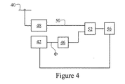
図4に示す第2の実施形態の方法では、USB40を通るトラフィックを監視し、すべてのSOFパケットをデコードする回路を用いる。ローカル制御されるクロック発振器42からの信号Φは、位相及び周波数において、USBの1kHzのSOFパケットにロックされる。このためにはまず、クロック発振器42からの信号Φをクロック分周器46でSOFパケットの周波数まで分周する必要がある(たとえば、1MHzの出力周波数を1kHzに分周する)。SOFパケットが(公称1kHzで)到着すると、整合フィルタ48からクロック同期信号50が位相検知器52に送られる。位相検知器52は、フィルタ56を介して、制御対象のクロック発振器42に接続されている。
In the method of the second embodiment shown in FIG. 4, a circuit that monitors traffic passing through the
ローカルクロック信号Φは、その後、USBデバイスのトランスデューサ回路に供給され、これによって、ルートハブに接続されているすべてのデバイスが同じ周波数にロックされる。 The local clock signal Φ is then supplied to the transducer circuit of the USB device, which locks all devices connected to the root hub to the same frequency.
この実施形態では、任意の高い周波数の安定したクロック信号を生成することが可能である(たとえば、確率的ジッタが数ナノ秒程度である数十メガヘルツのクロック周波数を生成できる)。したがって、この実施形態により、特定のUSBに接続された各デバイスのローカルクロックの周波数を同期させることができる。ただし、この実施形態では、それらのクロックの同時性が考慮されていない。各クロックの周波数と位相は、受信したSOFトークンにロックされるが、各デバイスがSOFパケットを受信するタイミングは、ランダムに接続されたUSBスタートポロジの信号伝搬時間の違いのために、実質的に異なる。複数のUSBデバイスのそれぞれのローカルクロックを(すべてのクロックが同相となるように)同期させるには、ホストから各デバイスまでの前記信号伝搬時間がわかっていなければならない。 In this embodiment, it is possible to generate a stable clock signal of any high frequency (for example, a clock frequency of tens of megahertz with a stochastic jitter on the order of a few nanoseconds). Therefore, according to this embodiment, the frequency of the local clock of each device connected to a specific USB can be synchronized. However, in this embodiment, the simultaneity of these clocks is not taken into consideration. The frequency and phase of each clock is locked to the received SOF token, but the timing at which each device receives the SOF packet is substantially due to the difference in signal propagation time of the randomly connected USB star topology. Different. In order to synchronize the local clocks of a plurality of USB devices (all clocks are in phase), the signal propagation time from the host to each device must be known.
第3の実施形態では、複数のUSBデバイスのそれぞれのローカルクロックを任意の精度で同期させる。電気的遅延やケーブル遅延に起因する、異なるデバイスのローカルクロック間の位相差を取得して補償するために、USBツリー内の種々の接続点でUSBトラフィックを監視し、特定のUSB通信トランザクションの伝搬時間を測定する。この実施形態では、存在する各デバイスについて、ホストからデバイスまでの特定のデータパケットと、このデータパケットに関連付けられた、デバイスからのUSB肯定応答ACKトークンの往復伝搬遅延時間を測定する。この情報を用いて、各デバイスのローカルクロックの相対位相を制御し、それによって、接続されているすべてのUSBデバイスを任意の精度で互いに同期させる。 In the third embodiment, the local clocks of the plurality of USB devices are synchronized with arbitrary accuracy. Monitor USB traffic at various connection points in the USB tree and propagate specific USB communication transactions to obtain and compensate for phase differences between local clocks of different devices due to electrical or cable delays Measure time. In this embodiment, for each device present, the round trip propagation delay of a specific data packet from the host to the device and the USB acknowledgment ACK token from the device associated with this data packet is measured. This information is used to control the relative phase of each device's local clock, thereby synchronizing all connected USB devices to each other with arbitrary accuracy.
USB仕様では、2つのデバイスのローカル時刻が最大で380ナノ秒異なってもよいとされている。しかしながら、2つの独立したデバイスが同じイベントの実時間を正確に記録するためには、それらのローカル時刻が事実上任意の精度で特定されなければならない。 According to the USB specification, the local time of two devices may differ by a maximum of 380 nanoseconds. However, in order for two independent devices to accurately record the real time of the same event, their local time must be specified with virtually any accuracy.
図5Aは、USBチェーン64内の異なる点に接続されている2つのデバイス60及び62を示している。USBチェーン64にはまた、USBホストコントローラ66と複数の7ポートUSBハブ68も含まれている。デバイス60及び62は、両方とも、同じ周期的SOF信号を受信し、それぞれが独自にそれぞれのローカルクロックの周波数と位相をそのSOF信号にロックさせている。ただし、USBホストコントローラ66とデバイス62の間にあるUSBハブ68の数が多いことによるトポロジカルな時間遅延のために、デバイス62は、デバイス60より遅れてSOFパケットを受信する。この時間差を時間遅延の測定結果から算出し、補正する必要がある。
FIG. 5A shows two
デバイス60の接続点の具体的な場所は、それが、図5Aに記号「A」で示すように、デバイス60が自身及びデバイス62のバストラフィックをデコードできるような位置でありさえすれば、重要ではない(つまり、デバイス60は、同期が必要なすべてのデバイスのバストラフィックをデコードできなければならない)。したがって、デバイス60の接続点は、図5Aに示すように、USBツリー又はチェーンの実質的に最上位付近であることが好ましい。
The specific location of the connection point of
前記往復伝搬遅延時間を測定するために、ホストとデバイス62の間でUSBトランザクションを実行する。デバイス60は、ツリー内の点「A」でUSBトラフィックを監視し、トランザクションのダウンストリームデータパケットと応答データパケットの通過を検知する。それによって、デバイス60は、図5Aの点「A」における、ホストからデバイス62へのダウンストリーム信号(トランザクションの開始)の検知と、デバイス62からホストへの応答信号(トランザクションの終了)の検知との時間間隔を求めることが可能になる。好ましい実施形態では、デバイス62からホストへの応答信号は、トランザクション肯定応答ACKパケットのACKトークンである。
In order to measure the round trip propagation delay time, a USB transaction is executed between the host and the
点「A」を基準とする、ホストとデバイス60の間のUSBトランザクションの往復伝搬遅延時間も、同様の方法で求めることができる。デバイス60とデバイス62において周波数ロックされたクロックの間の、接続トポロジに基づく時間的位相シフトの量は、同じ点「A」を基準とする、2つのデバイスの往復伝搬遅延時間の差のほぼ半分になる。したがって、デバイス62において周波数ロックされたクロックは、その量だけ、デバイス60において周波数ロックされたクロックより位相が遅れている。デバイス60及び62におけるクロックを、周波数と位相の両方において同期させるには、前記量に対応する位相オフセットをいずれかのクロックに施さなければならない。これは、デバイス60に対してローカルなクロック信号に位相遅延を施すことによって行われることが最も多い。
The round trip propagation delay time of the USB transaction between the host and the
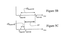
この方法を、図5B及び5Cでさらに説明する。図5Bは、図5Aのトランザクションの、デバイス62に関するタイミング図であり、図5Cは、図5Aのトランザクションの、デバイス60に関するタイミング図である。デバイス60及び62のそれぞれに対して、USBトランザクションは、TStart Xの時点で開始され、デバイスがACKパケットを返すTACK Xの時点で終了する(いずれの場合もXはデバイス番号を表す)。これらのトランザクションは同時には開始されないが、図は、トランザクションの相対的な継続時間を示すために、TStart Xを基準として配置されている。デバイス60は、図5Aの検知点「A」に非常に近いため、往復伝搬遅延時間がデバイス62の場合より著しく短い。伝搬時間の差をΔTで示す。したがって、2つの周波数ロックされたクロックの間の位相オフセットは、(1/2)ΔTになる。
This method is further illustrated in FIGS. 5B and 5C. FIG. 5B is a timing diagram for the
当業者であれば、必要な位相補正量を求める方法がほかにもあることは明らかであろう。また、当業者であれば、ローカルクロック周波数を発生させ、往復伝搬遅延時間又は片方向伝搬遅延時間を求めるために使用できる他のUSBデータプロトコルとして、任意のUSB制御及び管理パケットトークン(すなわち、SOF、IN、OUT、ACK、NAK、PRE、STALL、DATA0、DATA1)、USBデータパケット内のビットパターンの任意のプログラマブルシーケンス、任意のユーザ定義データ構造体、USB仕様で定義されている任意の信号プロトコルなどがあり、これらに限定されないことを理解されよう。 It will be apparent to those skilled in the art that there are other ways to determine the amount of phase correction required. Also, those skilled in the art can generate any local clock frequency and use any USB control and management packet token (ie, SOF) as another USB data protocol that can be used to determine the round trip or one way propagation delay time. IN, OUT, ACK, NAK, PRE, STALL, DATA0, DATA1), any programmable sequence of bit patterns in the USB data packet, any user-defined data structure, any signal protocol defined by the USB specification It will be understood that, but not limited to.
ここまで、USBデバイスのローカル発振器の位相及び周波数をロックさせて多数の多種多様なUSBデバイスの同期動作を実現する手法について説明した。このローカル発振器は、連続変調を発生させる。USBデバイスはまた、特定の操作シーケンスを時間的に同期させることを必要とされる場合がある。これを実現するために、USBデバイスは、いわゆる共通トリガ信号を必要とする。このトリガ信号を、周波数ロックされたローカル発振器と組み合わせて用いることによって、複数の独立したUSBデバイスの完全な同期動作を実現できる。 Up to this point, a method has been described in which the phase and frequency of the local oscillator of the USB device are locked to realize the synchronization operation of many different USB devices. This local oscillator generates continuous modulation. USB devices may also be required to synchronize specific operating sequences in time. In order to realize this, the USB device requires a so-called common trigger signal. By using this trigger signal in combination with a frequency-locked local oscillator, a complete synchronization operation of a plurality of independent USB devices can be realized.
第4の実施形態では、所定の時刻にトランスデューサをトリガするために、エンコードされたフレーム番号を含むSOFパケットを用いて、特定デバイス上のトランスデューサに対する同期トリガ信号を生成する。ただし、USB接続トポロジが原因で、SOFパケットの到着時刻がデバイス間で異なる可能性があり、さらに、USB仕様では、位相ロックされたローカル発振器に対して許容されているSOFパケット周波数の時間ジッタがかなり大きい。このため、クロックの位相が1周期の何分の1かずれる可能性がある。しかし、トリガ信号は、ローカル発振器と同相でなければならない。 In the fourth embodiment, in order to trigger the transducer at a predetermined time, the SOF packet including the encoded frame number is used to generate a synchronization trigger signal for the transducer on the specific device. However, due to the USB connection topology, the arrival time of the SOF packet may be different between devices. Furthermore, in the USB specification, the time jitter of the SOF packet frequency allowed for the phase-locked local oscillator is small. Pretty big. For this reason, the phase of the clock may be shifted by a fraction of one cycle. However, the trigger signal must be in phase with the local oscillator.
ジッタの問題を除去するために、SOF信号はローカル発振器の出力でラッチされる。このラッチによって、SOFトリガ要求の到着が記憶されるが、トリガ信号が生成されるのは、ローカル発振器の状態が次に変化したときである。異なるデバイス間のトリガ時刻の誤差は、デバイスのローカルクロック周波数と制御ループの特性の関数であって、任意に小さくすることができる。 In order to eliminate the jitter problem, the SOF signal is latched at the output of the local oscillator. This latch stores the arrival of the SOF trigger request, but the trigger signal is generated the next time the state of the local oscillator changes. The trigger time error between different devices is a function of the local clock frequency of the device and the characteristics of the control loop, and can be arbitrarily reduced.
そこで、図6の概略図で示される回路70では、USB72を監視し、ローカルクロック74からのクロック信号Φを、(必要に応じてクロック分周器76で出力周波数を1kHzまで下げ、)位相及び周波数において、USB72の1kHzのSOFパケットにロックさせる。第1の整合フィルタ80は、前記ローカルクロック74を(図4と同様に)周波数ロック及び位相ロックするために、SOFパケットが到着した時点でクロック同期信号82を出力し、第2の整合フィルタ84は、特定のフレーム番号を有するSOFパケットが到着した時点でトリガ要求信号86を出力する。図4の回路と同様に、この回路もフィルタ90と位相検知器92を含む。トリガ要求信号は、ローカルに安定化されたローカルクロック信号Φでラッチされ、それによって同期トリガ信号「Trig」が生成される。
Therefore, in the
第5の実施形態では、回路及びロジックを用いて、各国の標準(NISTやNATAなど)にトレーサブルな周波数でUSBデバイスに同期信号を供給する。これは、たとえば、ルートハブを含む任意のハブのクロック及び/又は水晶振動子を、国家標準にトレーサブルな周波数基準に置き換えることによって実現される。 In the fifth embodiment, a synchronization signal is supplied to a USB device at a frequency traceable to a standard (NIST, NATA, etc.) of each country using a circuit and logic. This can be achieved, for example, by replacing the clock and / or quartz crystal of any hub including the root hub with a frequency reference traceable to national standards.
第6の実施形態では、USBバックプレーンを設けて、接続可能なデバイスに、電力、USB信号、コネクタ、及び同期情報を供給する。 In the sixth embodiment, a USB backplane is provided to supply power, a USB signal, a connector, and synchronization information to connectable devices.
USBバックプレーンは、その最も複雑な形態では、自己給電式デバイス用としてUSBに追加する電力、多数の多種多様なポートを提供するハブ回路、複数のホットプラグ可能デバイス接続点を提供するポートに関連付けられた複数のコネクタ、及びUSB仕様を満たすUSB信号を含む。USBバックプレーンはさらに、前述の様々な手法ならびに電源オン/オフシーケンスを用いて周波数、位相、トリガを含む同期情報を整理及び提供するために、マイクロプロセッサなどのロジック要素、プログラマブルアレイ、デジタル電子回路、及びアナログ電子回路を含むこともできる。バックプレーンは、1つ又は複数のハブに加えて、そのハブによって提供されるUSBポートの1つに接続されたデバイスを含むこともできる。あるいは、バックプレーンは、ハブ機能と同期機能を提供する複合デバイスであることも可能である。これらにより、同期情報を、運用中に測定したり、プログラムしたりできる。
[実施例]
The USB backplane, in its most complex form, is associated with power added to the USB for self-powered devices, hub circuits that provide many different ports, and ports that provide multiple hot-pluggable device attachment points A plurality of connectors, and a USB signal that satisfies the USB specification. The USB backplane further includes logic elements such as microprocessors, programmable arrays, digital electronic circuits to organize and provide synchronization information including frequency, phase, and trigger using the various techniques and power on / off sequences described above. And analog electronic circuitry. In addition to one or more hubs, the backplane can also include devices connected to one of the USB ports provided by the hub. Alternatively, the backplane can be a composite device that provides a hub function and a synchronization function. As a result, the synchronization information can be measured or programmed during operation.
[Example]
上記の各実施形態は、様々な形で用いることができる。ただし、それらは、USBコネクタ端子に同期端子を追加するデバイスとそうでないデバイスとに分けることができる。さらに、第2から第5までの実施形態のロジック要素を、USBデバイス上に配置したり、バックプレーン上に配置したり(バックプレーンソリューションが必要な場合)、その両方に配置したり、まったく配置しなかったりできる。 Each of the above embodiments can be used in various forms. However, they can be divided into devices that add a synchronization terminal to the USB connector terminal and devices that do not. In addition, the logic elements of the second to fifth embodiments can be placed on the USB device, on the backplane (if a backplane solution is required), on both, or at all You can not.
用途ごとの要件に応じて、バックプレーンソリューションの実装が必要な場合と必要でない場合があることは理解されよう。また、デバイスに追加電力を供給する必要があるかどうかも用途によって決まる。 It will be appreciated that a backplane solution may or may not be implemented depending on the requirements of each application. The application also determines whether additional power needs to be supplied to the device.
同期用コネクタ配線を追加しない場合
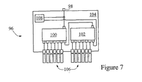
追加同期信号に依存しない、本発明によるシステムの利点は、デバイスがその情報に依存せずに同期動作できるために、任意のスタンドアロンホストで普通のハブを使用できることである。そのようなシステムは、非常に精度の高い同期を必要とするデバイスにも拡張できる。図7では、そのようなシステムの例を96として概略的に示している。96は、アップストリームUSBポート98と複数のバックプレーンハブデバイス100及び102(この例ではそれぞれがバックプレーン104上の7ポートUSBハブ)を有する。100及び102は、複数のデバイス106に追加電力を任意に供給できる。各デバイス106は、前述の第2の実施形態に従って周波数ロック及び位相ロックされたローカルクロックを含むことができる。バックプレーン104とハブ100及び102は、デバイス108及び第3の実施形態の文脈において前述した手法を用いて(それぞれのケーブル長がUSB仕様の範囲内でランダムである)デバイス106間の位相差を調節する機能を有する。さらに、各デバイス106は、第3の実施形態の文脈において前述した手法に従って動作するローカルクロック用位相シフトジェネレータを含む。
Without additional synchronization connector wiring The advantage of the system according to the present invention, which does not rely on additional synchronization signals, is that a normal hub can be used on any standalone host because the device can operate synchronously without relying on that information. is there. Such a system can be extended to devices that require very accurate synchronization. FIG. 7 schematically shows an example of such a system as 96. 96 has an
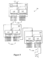
図8は、多数の同期USBデバイスを含む複雑なシステムを96として概略的に示している。アップストリームポート111は、ホストからのUSB情報を受信する。システム110は、複数のバックプレーン112、113、114を含み、各バックプレーンは2つのバックプレーンハブデバイス115を備える。各バックプレーンハブデバイス115は、7ポートUSBハブを備え、複数のデバイス116に追加電力を任意に供給できる。各デバイス116は、前述の第2の実施形態に従って周波数ロック及び位相ロックされたローカルクロックを含むことができる。また、第1の(又はマスタ)バックプレーン112はさらに、(図7と同様に)追加の回路又はロジック要素117を有し、要素117及び第3の実施形態の文脈において前述した手法を用いて(それぞれの接続トポロジが異なる)デバイス116間の位相差を調節する機能を有する。さらにまた、各デバイス116は、第3の実施形態の文脈において前述した手法を用いてローカルクロックを位相シフトする位相シフトジェネレータを含む。ダウンストリームポート118には、USB仕様で定義されている最大数である127個までのデバイス及び/又はハブ及び/又はバックプレーンを追加接続できる。
FIG. 8 schematically illustrates a complex system including a number of synchronous USB devices as 96. The
さらに、アップストリームルートハブから供給される周波数を、第5の実施形態に従って周波数基準を用いて発生させることができ、第4の実施形態の方法を用いて任意のトリガ信号を発生させることができる。 Further, the frequency supplied from the upstream root hub can be generated using a frequency reference according to the fifth embodiment, and an arbitrary trigger signal can be generated using the method of the fourth embodiment.
同期用追加コネクタ配線
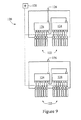
前述した各実施形態に従う方法の最もシンプルな例は、USB及び同期情報を収容する独自のコネクタか、USBコネクタと別個の同期リンクとを介して、すべてのデバイスを共通同期信号に接続することによって実現できる。同期情報はUSBトラフィックに依存しないため、任意の周波数を用いることには特に問題はない。同期情報の媒体としては、無線手段、電気的手段、光ファイバ手段などを任意に用いることができる。図9は、そのような回路の実用的な例を120として概略的に示している。回路120は、本質的に、それぞれが図7の回路に相当する回路の対を含み、7ポートUSBハブ124を介して24個のUSBデバイス122が接続されるようになっている。そしてこれらのデバイスを、アップストリームUSBポート126を介してPCに接続できる。USB接続トポロジは、同期信号には何ら影響を及ぼさない。同期信号は、別個に、周波数Φの外部クロック128からデバイスに供給される。したがって、デバイス122は、(USB要件と追加接続とを収容する)1つのコネクタか、標準USBコネクタ及び1つ又は複数の追加コネクタを介してUSB及び同期信号に接続される。
Additional connector wiring for synchronization The simplest example of the method according to each of the above-described embodiments is that a common synchronization signal is sent to all devices via a unique connector that accommodates USB and synchronization information, or a USB connector and a separate synchronization link. It can be realized by connecting to. Since the synchronization information does not depend on the USB traffic, there is no problem in using an arbitrary frequency. As the synchronization information medium, wireless means, electrical means, optical fiber means, and the like can be arbitrarily used. FIG. 9 schematically shows a practical example of such a circuit as 120. The
この例のより複雑な形態では、追加のロジック要素を含むバックプレーンが用いられ、このロジック要素が、正確な制御を行い、接続されているすべてのデバイスの周波数と位相をロックする。このような構成では、前述した第2及び第3の実施形態の方法に従い、バックプレーンのロジック要素がUSBトラフィックを監視し、それぞれ独自のローカルクロックを発生させる。この、バックプレーンが発生させたクロックは、前述した1つ又は複数のバックプレーンコネクタを介して、接続されている各USBデバイスに分配される。 In a more complex form of this example, a backplane is used that includes additional logic elements that provide precise control and lock the frequency and phase of all connected devices. In such a configuration, the backplane logic elements monitor USB traffic and generate their own local clocks according to the methods of the second and third embodiments described above. The clock generated by the backplane is distributed to each connected USB device via the one or more backplane connectors described above.
図10は、そのような構成を130として概略的に示している。各デバイス132は、USB仕様を補う追加コネクタ端子136(電気的、無線、又は光ファイバ)を介して回路134に接続されている。一例として、この回路は、様々なモジュールが接続されるバックプレーン138に配置できる。このバックプレーン138はさらに、1つ又は複数の7ポートUSBハブ140を含む。回路134は、(第2の実施形態に従い)USBアップストリームポート142においてUSBをフレーム開始信号に関して監視し、その内部クロックの周波数及び位相をフレーム開始信号にロックさせる。回路134はさらに、USBトポロジに起因する遅延を補正するために、着信クロック信号を任意に遅延させることができる(第3の実施形態を参照)。その内部クロックは、追加コネクタ端子を介して各デバイス132で利用できる。このようにして、すべてのデバイス132が、同期すべき共通クロック信号を受け取る。
FIG. 10 schematically illustrates such a configuration as 130. Each
これまで示した各図では、同期回路をハブと分離して描いていることに注目されたい。これに対し、図11で150として示した別の変形形態では、1つのハブが、(USBアップストリームポート154に接続され、)拡張ポート156及び同期回路158の両方を含む複合デバイス152になっている(同期回路158は、第2の実施形態に従ってローカルクロック信号を発生させ、第3の実施形態の手法を用いてローカルクロックを位相シフトさせて他のデバイスとの同期をとる)。これにより、(これまで説明した例と比較して)第2のハブ162のポート160が自由になり、図11に示したシンプルな構成では、最大13個のデバイス164を接続できる。
Note that in the figures shown so far, the synchronization circuit is depicted separately from the hub. In contrast, in another variation shown as 150 in FIG. 11, one hub becomes a composite device 152 (connected to the USB upstream port 154) that includes both the
また、USB仕様では、ハブ当たりのポート数が7に制限されていないことにも注意されたい。したがって、図10では、1つのハブ140が、たとえば12個のポートをサービスするようにできる。
Also note that the USB specification does not limit the number of ports per hub to seven. Thus, in FIG. 10, one
当業者であれば、本発明の趣旨及び範囲を逸脱しない修正を容易に行うことができよう。したがって、本発明は、ここまで例として説明してきた具体的な実施形態に限定されないことを理解されたい。本明細書の目的のためには、「含む(備える)」という語が「含む(備える)が、それに限定されない」という意味であることを理解されたい。 Those skilled in the art will readily be able to make modifications without departing from the spirit and scope of the present invention. Accordingly, it should be understood that the present invention is not limited to the specific embodiments that have been described by way of example. For the purposes of this specification, it should be understood that the word “comprising” means “including but not limited to”.
さらに、本明細書における従来技術の参照はすべて、それらの従来技術が共通一般知識の一部を形成する(又は形成した)ように示すことを意図したものではない。
Furthermore, all prior art references herein are not intended to indicate that such prior art forms (or has formed) part of the common general knowledge.
10’ 同期ユニバーサルシリアルデバイス
12 トランスジューサ
14 バスコントローラ
16 デジタルI/Oバス転送回路
18 マイクロプロセッサ
20 同期チャンネル
22 デジタルバス
24 外部ソース
10 'synchronous universal
Claims (50)
外部ソースから同期情報を供給するようにUSB仕様の信号チャネルを補う方法。 A method for providing a synchronous multi-channel universal serial bus, comprising:
A method of supplementing USB-specific signal channels to supply synchronization information from an external source.
USBトラフィックを監視するステップと;
USBデバイスのローカルクロック信号をUSBデータトラフィックに含まれる周期的な信号にロックさせるステップと;を備え、
前記ロックさせるステップを、位相若しくは周波数、又は位相と周波数の両方について行う方法。 A method of synchronizing a multi-channel universal serial bus,
Monitoring USB traffic;
Locking the local clock signal of the USB device to a periodic signal included in the USB data traffic;
A method of performing the locking step with respect to phase or frequency, or both phase and frequency.
USBツリー内の複数の点でUSBトラフィックを監視するステップと;
複数の個別パケットのそれぞれの往復遅延時間を測定するステップと;
前記それぞれの往復遅延時間から前記ツリー内の個々のUSBデバイスの相対位相を求めるステップと;を備え、
前記個々のUSBデバイスのそれぞれの位相オフセットを前記求めた相対位相に従って調整できる方法。 A method of synchronizing a multi-channel universal serial bus,
Monitoring USB traffic at a plurality of points in the USB tree;
Measuring the round trip delay time of each of a plurality of individual packets;
Determining a relative phase of each USB device in the tree from the respective round trip delay times;
A method in which a phase offset of each of the individual USB devices can be adjusted according to the obtained relative phase.
USBトポロジ内のすべてのデバイスにトリガ信号を発行するステップを含む方法。 A method for providing a synchronous multi-channel universal serial bus, comprising:
Issuing a trigger signal to all devices in the USB topology.
USBトポロジ内のすべてのデバイスにトリガ信号を発行する回路を備えたユニバーサルシリアルバス。 A synchronous multi-channel universal serial bus,
Universal serial bus with circuitry to issue trigger signals to all devices in the USB topology.
USBデータトラフィック内で送信する特定の信号構成を生成又は指定するステップと;
前記特定の信号構成を所定のシーケンスで前記USBデバイスに送信するステップと;
前記USBデバイスに対してローカルなUSB信号を、前記特定の信号構成に関して監視するステップと;
前記特定の信号構成から、前記USBデバイスのそれぞれにおけるローカル基準信号を生成するステップと;
前記USBデバイスのそれぞれにおける前記ローカルクロック信号の周波数を所定の精度で前記ローカル基準信号にロックさせるステップと;を備えた方法。 A method of locking local clocks of a plurality of USB devices in the same USB tree to substantially the same frequency,
Generating or specifying a specific signal configuration to transmit in USB data traffic;
Transmitting the specific signal configuration to the USB device in a predetermined sequence;
Monitoring a USB signal local to the USB device for the specific signal configuration;
Generating a local reference signal in each of the USB devices from the specific signal configuration;
Locking the frequency of the local clock signal in each of the USB devices to the local reference signal with a predetermined accuracy.
前記USBツリー内でマスタUSBデバイスを指定するステップと;
USBデータトラフィック内で送信する特定の信号構成を生成又は指定するステップと;
前記特定の信号構成を所定のシーケンスで前記USBデバイスに送信するステップと;
前記マスタUSBデバイスを用いて、前記USBトラフィックを、前記特定の信号構成及び前記USBデバイスからの特定の応答信号に関して監視するステップと;
前記特定の信号構成のデコード結果に対応する、前記マスタUSBデバイスに対してローカルなイベントトリガ信号を生成するステップと;
前記USBデバイスからの応答信号のデコード結果に対応する、前記マスタUSBデバイスに対してローカルなイベントトリガ信号を生成するステップと;
前記マスタUSBデバイスにおいて前記イベントトリガ信号間の時間間隔を測定するステップと;
前記USBホストから前記USBデバイスまでの伝搬時間を、前記時間間隔から求めるステップと;を備える方法。 A method for measuring a propagation time of a signal from a USB host to a USB device in a USB tree,
Designating a master USB device in the USB tree;
Generating or specifying a specific signal configuration to transmit in USB data traffic;
Transmitting the specific signal configuration to the USB device in a predetermined sequence;
Using the master USB device to monitor the USB traffic for the specific signal configuration and a specific response signal from the USB device;
Generating an event trigger signal local to the master USB device corresponding to the decoding result of the specific signal configuration;
Generating an event trigger signal local to the master USB device corresponding to the decoding result of the response signal from the USB device;
Measuring a time interval between the event trigger signals at the master USB device;
Obtaining a propagation time from the USB host to the USB device from the time interval.
請求項26記載の方法に従って前記USBデバイスのそれぞれと前記USBホストの間のそれぞれの伝搬遅延を求めるステップと;
前記USBデバイスの1つを時間的基準デバイスとして指定するステップと;
前記時間的基準デバイスと前記複数の前記USBデバイスのそれぞれとの間の前記伝搬遅延の差を求めるステップと;を備える方法。 A method for determining a relative propagation delay of an electrical signal or data structure between a plurality of USB devices connected to a common USB host,
27. determining a respective propagation delay between each of the USB devices and the USB host in accordance with the method of claim 26;
Designating one of the USB devices as a temporal reference device;
Determining the difference in propagation delay between the temporal reference device and each of the plurality of USB devices.
請求項18に記載の方法に従って、前記USBデバイスのそれぞれのローカルクロックを実質的に同じ周波数にロックさせるステップと;
請求項26に記載の方法に従って、前記USBデバイスのうちの選択された1つを基準とする、前記USBホストから前記USBデバイスのそれぞれまでの信号の相対的な伝搬遅延を求め、前記USBデバイスのうちの前記選択された1つが基準USBデバイスとして指定されるステップと;
請求項31に記載の方法に従って、前記基準USBデバイスの前記ローカルクロックを基準とする、前記複数のUSBデバイスのそれぞれの前記ローカルクロックの相対位相を求めるステップと;
前記USBツリー全体の前記複数のローカルクロックを実質的に同相にするために必要な、前記ローカルクロックのそれぞれの時間調整量又は位相オフセット量を求めるステップと;
前記時間調整量又は位相オフセット量を前記USBホストから前記USBデバイスに送信するステップと;
それぞれの前記時間調整量又は位相オフセット量に従って前記USBデバイスのそれぞれに対して前記ローカルクロックの位相調整を実施するステップと;を備える方法。 A method of synchronizing local clocks of a plurality of USB devices connected to a common USB host via a USB tree so as to have substantially the same phase and substantially the same frequency,
19. Locking each local clock of the USB device to substantially the same frequency according to the method of claim 18;
27. Finding a relative propagation delay of a signal from the USB host to each of the USB devices relative to a selected one of the USB devices according to the method of claim 26; The selected one of them is designated as a reference USB device;
32. According to the method of claim 31, determining a relative phase of each of the local clocks of the plurality of USB devices relative to the local clock of the reference USB device;
Obtaining a time adjustment amount or a phase offset amount of each of the local clocks necessary for making the plurality of local clocks of the entire USB tree substantially in phase;
Transmitting the time adjustment amount or phase offset amount from the USB host to the USB device;
Performing the phase adjustment of the local clock on each of the USB devices according to the respective time adjustment amount or phase offset amount.
請求項32に記載の方法に従って前記USBデバイスのそれぞれのローカルクロックを同期させるステップと;
トリガ要求及び前記トリガコマンドをそれぞれ表す所定のトリガ要求信号及び所定のトリガコマンド信号をUSBデータトラフィック内で送信するステップと;
前記USBデバイスのそれぞれに対してローカルな前記USBデータトラフィックを、前記トリガ要求信号及び前記トリガコマンド信号に関して監視するステップと;
前記USBデバイスが前記トリガ要求を実質的に同時に実行に移すよう前記USBデバイスを準備するために、前記USBホストを用いて開始トリガ要求信号を前記USBデバイスのそれぞれに送信するステップと;
前記USBデバイスが前記トリガ信号の受信後ただちに前記プロセスを実行するよう準備することによって前記開始トリガ要求信号に応答するよう前記USBデバイスを構成するステップと;
前記USBホストが前記複数の前記USBのそれぞれに対して前記トリガコマンドを発行するよう前記USBホストを構成するステップと;
前記USBデバイスを用いて前記トリガコマンドをデコードするステップと;
前記USBデバイスが前記プロセスを実質的に同時に実行するよう前記USBデバイスを構成するステップと;を備え、
前記USBデバイス内の1つ又は複数のプロセスを、前記USBホストからの前記トリガコマンド信号の受信後ただちに開始又は停止する方法。 A method of starting or stopping one or more processes in a plurality of USB devices connected to a common USB host by synchronously triggering according to a predetermined trigger command,
Synchronizing the respective local clocks of the USB devices according to the method of claim 32;
Transmitting a predetermined trigger request signal and a predetermined trigger command signal representing the trigger request and the trigger command, respectively, in the USB data traffic;
Monitoring the USB data traffic local to each of the USB devices with respect to the trigger request signal and the trigger command signal;
Sending a start trigger request signal to each of the USB devices using the USB host to prepare the USB device for the USB device to execute the trigger request substantially simultaneously;
Configuring the USB device to respond to the start trigger request signal by preparing the USB device to execute the process immediately after receiving the trigger signal;
Configuring the USB host such that the USB host issues the trigger command to each of the plurality of USBs;
Decoding the trigger command using the USB device;
Configuring the USB device such that the USB device performs the process substantially simultaneously, and
A method of starting or stopping one or more processes in the USB device immediately after receiving the trigger command signal from the USB host.
USBデータトラフィック内での特定の信号構成の生成と、所定のシーケンスでの前記特定の信号構成の前記USBデバイスへの送信と、前記USBデバイスのそれぞれにおける前記特定の信号構成からのローカル基準信号の生成とを行う信号ジェネレータと:
前記USBデバイスに対してローカルなUSB信号を、前記特定の信号構成に関して監視する信号モニタと:を備え、
前記USBデバイスのそれぞれにおける前記ローカルクロック信号の前記周波数を所望の精度で前記ローカル基準信号にロックさせることができる装置。 A device that locks the local clock of each of a plurality of USB devices in the same USB tree to substantially the same frequency,
Generation of a specific signal configuration within USB data traffic, transmission of the specific signal configuration to the USB device in a predetermined sequence, and local reference signals from the specific signal configuration at each of the USB devices And a signal generator that generates:
A signal monitor for monitoring a USB signal local to the USB device with respect to the specific signal configuration;
An apparatus capable of locking the frequency of the local clock signal in each of the USB devices to the local reference signal with a desired accuracy.
前記USBツリー内のUSBデバイスの1つからなるマスタUSBデバイスと;
USBデータトラフィック内での特定の信号構成の生成と、所定のシーケンスでの前記特定の信号構成の前記USBデバイスへの送信とを行う信号ジェネレータ又はルートハブと;
前記マスタUSBデバイスを用いて前記USBトラフィックを、前記特定の信号構成及び前記応答信号に関して監視する信号モニタと;
前記マスタUSBデバイスにおいて前記イベントトリガ信号間の時間間隔を測定するタイマと;を備え、
前記USBホストから前記USBデバイスまでの伝搬時間を、前記時間間隔から求めることができる装置。 An apparatus for measuring a propagation time of a signal from a USB host to a USB device in a USB tree,
A master USB device consisting of one of the USB devices in the USB tree;
A signal generator or root hub for generating a specific signal configuration within USB data traffic and transmitting the specific signal configuration to the USB device in a predetermined sequence;
A signal monitor that monitors the USB traffic with respect to the specific signal configuration and the response signal using the master USB device;
A timer for measuring a time interval between the event trigger signals in the master USB device;
An apparatus that can determine a propagation time from the USB host to the USB device from the time interval.
請求項45に記載したように前記USBデバイスのそれぞれと前記USBホストの間のそれぞれの伝搬時間を求める装置と;
基準USBデバイスと前記複数の前記USBデバイスのそれぞれとの間の前記伝搬時間の差を求める計算手段と;を備え、
前記基準USBデバイスが前記USBデバイスのうちの1つからなる装置。 An apparatus for determining a relative propagation delay of an electrical signal or a data structure between a plurality of USB devices connected to a common USB host,
46. An apparatus for determining a propagation time between each of the USB devices and the USB host as recited in claim 45;
Calculating means for determining a difference in the propagation time between a reference USB device and each of the plurality of USB devices;
An apparatus in which the reference USB device is one of the USB devices.
前記USBデバイスのそれぞれの前記ローカルクロックを、請求項44に記載したように、実質的に同じ周波数にロックさせる装置と;
基準USBデバイスを基準として、前記USBホストから前記USBデバイスのそれぞれまでの信号の相対的な伝搬遅延を求めることと、請求項46に記載したように、前記基準USBデバイスの前記ローカルクロックを基準として、前記複数のUSBデバイスのそれぞれの前記ローカルクロックの相対位相を求めることとを行い、前記基準USBデバイスが前記USBデバイスのうちの選択された1つからなる装置と;
前記USBツリー全体の前記複数のローカルクロックを実質的に同相にするために必要な、前記ローカルクロックのそれぞれの時間調整量又は位相オフセット量を求めるタイマと;を備え、
前記時間調整量又は位相オフセット量の前記USBホストから前記USBデバイスへの送信と、それぞれの前記時間調整量又は位相オフセット量に従う、前記USBデバイスのそれぞれにおける前記ローカルクロックの位相調整とを行うように構成された装置。 An apparatus for synchronizing local clocks of a plurality of USB devices connected to a common USB host via a USB tree so as to have substantially the same phase and substantially the same frequency,
45. A device for locking the local clock of each of the USB devices to substantially the same frequency as described in claim 44;
The relative propagation delay of a signal from the USB host to each of the USB devices is obtained with reference to a reference USB device, and the local clock of the reference USB device is used as a reference according to claim 46. Determining the relative phase of the local clock of each of the plurality of USB devices, and wherein the reference USB device comprises a selected one of the USB devices;
A timer for determining a time adjustment amount or a phase offset amount of each of the local clocks necessary for making the plurality of local clocks of the entire USB tree substantially in phase;
Transmission of the time adjustment amount or phase offset amount from the USB host to the USB device and phase adjustment of the local clock in each of the USB devices according to the respective time adjustment amount or phase offset amount are performed. Configured device.
44. A method according to any of claims 1 to 43 is implemented by implementing a real-time automatic control function and a data acquisition function using one or more USB devices at any connection point in the USB expansion hub. A device that behaves like
Applications Claiming Priority (2)
| Application Number | Priority Date | Filing Date | Title |
|---|---|---|---|
| US39609902P | 2002-07-17 | 2002-07-17 | |
| PCT/AU2003/000918 WO2004008330A1 (en) | 2002-07-17 | 2003-07-17 | Synchronized multichannel universal serial bus |
Related Child Applications (2)
| Application Number | Title | Priority Date | Filing Date |
|---|---|---|---|
| JP2009208701A Division JP5232110B2 (en) | 2002-07-17 | 2009-09-09 | Synchronous multi-channel universal serial bus system and method for synchronizing a plurality of USB devices connected to a multi-channel universal serial bus |
| JP2010110522A Division JP5378297B2 (en) | 2002-07-17 | 2010-05-12 | Synchronous multichannel universal serial bus |
Publications (1)
| Publication Number | Publication Date |
|---|---|
| JP2005533305A true JP2005533305A (en) | 2005-11-04 |
Family
ID=30115970
Family Applications (4)
| Application Number | Title | Priority Date | Filing Date |
|---|---|---|---|
| JP2004520197A Pending JP2005533305A (en) | 2002-07-17 | 2003-07-17 | Synchronous multichannel universal serial bus |
| JP2009208701A Expired - Fee Related JP5232110B2 (en) | 2002-07-17 | 2009-09-09 | Synchronous multi-channel universal serial bus system and method for synchronizing a plurality of USB devices connected to a multi-channel universal serial bus |
| JP2010110522A Expired - Fee Related JP5378297B2 (en) | 2002-07-17 | 2010-05-12 | Synchronous multichannel universal serial bus |
| JP2013155335A Expired - Fee Related JP5642852B2 (en) | 2002-07-17 | 2013-07-26 | USB device |
Family Applications After (3)
| Application Number | Title | Priority Date | Filing Date |
|---|---|---|---|
| JP2009208701A Expired - Fee Related JP5232110B2 (en) | 2002-07-17 | 2009-09-09 | Synchronous multi-channel universal serial bus system and method for synchronizing a plurality of USB devices connected to a multi-channel universal serial bus |
| JP2010110522A Expired - Fee Related JP5378297B2 (en) | 2002-07-17 | 2010-05-12 | Synchronous multichannel universal serial bus |
| JP2013155335A Expired - Fee Related JP5642852B2 (en) | 2002-07-17 | 2013-07-26 | USB device |
Country Status (10)
| Country | Link |
|---|---|
| US (3) | US7539793B2 (en) |
| EP (6) | EP1901178B1 (en) |
| JP (4) | JP2005533305A (en) |
| CN (3) | CN101281512A (en) |
| AT (4) | ATE487183T1 (en) |
| AU (3) | AU2003243837B2 (en) |
| CA (2) | CA2749078A1 (en) |
| DE (4) | DE60323992D1 (en) |
| HK (2) | HK1079302A1 (en) |
| WO (1) | WO2004008330A1 (en) |
Cited By (8)
| Publication number | Priority date | Publication date | Assignee | Title |
|---|---|---|---|---|
| JP2009527152A (en) * | 2006-02-15 | 2009-07-23 | クロノロジック ピーティーワイ リミテッド | Distributed synchronization and timing system |
| JP2010511868A (en) * | 2006-11-30 | 2010-04-15 | エレクトロ サイエンティフィック インダストリーズ インコーポレーテッド | Synchronous control of test instruments |
| JP2010527080A (en) * | 2007-05-15 | 2010-08-05 | クロノロジック プロプライエタリー リミテッド | Method and system for reducing trigger delay in data acquisition on universal serial bus |
| JP2010527081A (en) * | 2007-05-15 | 2010-08-05 | クロノロジック ピーティーワイ リミテッド | USB-based synchronization and timing system |
| JP2012500430A (en) * | 2008-08-21 | 2012-01-05 | クロノロジック ピーティーワイ リミテッド | Synchronization and timing method and apparatus |
| JP2012527658A (en) * | 2009-05-20 | 2012-11-08 | クロノロジック プロプライエタリー リミテッド | High density, low jitter synchronous USB expansion |
| JP2013050760A (en) * | 2011-08-30 | 2013-03-14 | Renesas Electronics Corp | Usb hub and control method of usb hub |
| JP2013254510A (en) * | 2002-07-17 | 2013-12-19 | Chronologic Pty Ltd | Usb devices |
Families Citing this family (42)
| Publication number | Priority date | Publication date | Assignee | Title |
|---|---|---|---|---|
| TWI247216B (en) * | 2004-04-09 | 2006-01-11 | Prolific Technology Inc | USB transmission interface device capable of reducing working current |
| US8108559B2 (en) * | 2003-07-11 | 2012-01-31 | Computer Associates Think, Inc. | Standardizing clocks in a networked computing environment |
| JP2005328280A (en) * | 2004-05-13 | 2005-11-24 | Canon Inc | Data processor |
| US7332597B2 (en) | 2004-06-28 | 2008-02-19 | University Of Kentucky Research Foundation | Primers and probe to identify mycobacterium tuberculosis complex |
| JP2006099666A (en) * | 2004-09-30 | 2006-04-13 | Hitachi Global Storage Technologies Netherlands Bv | Recording medium drive, and control method of power save mode in recording medium drive |
| TWI273367B (en) * | 2004-10-01 | 2007-02-11 | Fortune Semiconductor Corp | Method and device for calibrating monitor clocks |
| GB2424093B (en) * | 2005-03-08 | 2007-01-17 | Elan Digital Systems Ltd | Instrument and communications controller for instrument |
| CN1955949B (en) * | 2005-10-24 | 2010-05-26 | 瑞昱半导体股份有限公司 | Universal serial bus device |
| US8069294B2 (en) | 2006-03-30 | 2011-11-29 | Intel Corporation | Power-optimized frame synchronization for multiple USB controllers with non-uniform frame rates |
| TWI328930B (en) * | 2006-11-24 | 2010-08-11 | Sonix Technology Co Ltd | Frequency auto-locking device, usb device and frequency auto-locking method |
| US7818603B2 (en) | 2007-03-28 | 2010-10-19 | Microsoft Corporation | Deriving accurate media position information |
| US8036613B2 (en) * | 2007-05-07 | 2011-10-11 | Infineon Technologies Ag | Communication system and method for operating a communication system |
| AU2013200979B2 (en) * | 2007-05-15 | 2013-10-10 | Chronologic Pty Ltd | Usb based synchronization and timing system |
| US7804290B2 (en) * | 2007-09-14 | 2010-09-28 | Infineon Technologies, Ag | Event-driven time-interval measurement |
| TW200921325A (en) * | 2007-11-05 | 2009-05-16 | Holtek Semiconductor Inc | Frequency synchronous apparatus and method |
| US8700821B2 (en) | 2008-08-22 | 2014-04-15 | Intel Corporation | Unified multi-transport medium connector architecture |
| US8510589B2 (en) * | 2008-08-29 | 2013-08-13 | Intel Mobile Communications GmbH | Apparatus and method using first and second clocks |
| TWI533138B (en) * | 2009-05-19 | 2016-05-11 | 慧榮科技股份有限公司 | Signal generating apparatus and signal generating method |
| TWI423007B (en) * | 2009-12-31 | 2014-01-11 | Via Tech Inc | Serial bus device and clock difference compensation method thereof |
| CN102129414B (en) * | 2010-01-15 | 2013-12-04 | 华为技术有限公司 | Variable frequency bus adapter, adapting method and system |
| US8760188B2 (en) * | 2011-06-30 | 2014-06-24 | Silicon Image, Inc. | Configurable multi-dimensional driver and receiver |
| US9697159B2 (en) | 2011-12-27 | 2017-07-04 | Intel Corporation | Multi-protocol I/O interconnect time synchronization |
| US8775713B2 (en) | 2011-12-27 | 2014-07-08 | Intel Corporation | Multi-protocol tunneling over an I/O interconnect |
| US8953644B2 (en) | 2011-12-27 | 2015-02-10 | Intel Corporation | Multi-protocol I/O interconnect time synchronization |
| US8782321B2 (en) | 2012-02-08 | 2014-07-15 | Intel Corporation | PCI express tunneling over a multi-protocol I/O interconnect |
| US8880923B2 (en) | 2012-03-29 | 2014-11-04 | Intel Corporation | Link power management in an I/O interconnect |
| AU2013204757A1 (en) * | 2012-06-03 | 2013-12-19 | Chronologic Pty Ltd | Synchronisation of a system of distributed computers |
| US9203893B2 (en) * | 2013-03-08 | 2015-12-01 | Lincoln Global, Inc. | System and method for installing device drivers on welding equipment |
| US9830298B2 (en) * | 2013-05-15 | 2017-11-28 | Qualcomm Incorporated | Media time based USB frame counter synchronization for Wi-Fi serial bus |
| CN103309397B (en) * | 2013-06-17 | 2015-11-18 | 杭州锐达数字技术有限公司 | Based on the synchronous sampling method of the data acquisition equipment of USB |
| US8838846B1 (en) * | 2013-06-27 | 2014-09-16 | Crystal Instruments Corporation | Autonomous, multi-channel USB data acquisition transducers |
| TWI530799B (en) | 2013-11-28 | 2016-04-21 | 慧榮科技股份有限公司 | Frequency calibration method applicable in universal serial bus device and the related universal serial bus device |
| TWI533136B (en) * | 2013-12-05 | 2016-05-11 | 慧榮科技股份有限公司 | Frequency calibration method applicable in universal serial bus device and the related universal serial bus device |
| GB2538246B (en) * | 2015-05-11 | 2018-06-20 | Cirrus Logic Int Semiconductor Ltd | Digital accessory interface calibration |
| US9924482B2 (en) * | 2015-06-17 | 2018-03-20 | Hughes Network Systems, Llc | Unique word (UW) based multiple access message processing |
| US10061726B2 (en) | 2015-12-23 | 2018-08-28 | Intel Corporation | Precision time management (PTM) for USB retimers that accurately adjusts timestamp fields of isochronous timestamp packets (ITPS) |
| SG11201900499SA (en) * | 2016-07-29 | 2019-02-27 | Razer Asia Pacific Pte Ltd | Interface devices, methods for controlling an interface device, and computer-readable media |
| CN108366129B (en) * | 2018-03-08 | 2019-05-07 | 北京淳中科技股份有限公司 | USB data transmission method, device and USB are from device adapter |
| US10896106B2 (en) * | 2018-05-10 | 2021-01-19 | Teradyne, Inc. | Bus synchronization system that aggregates status |
| JP7222662B2 (en) * | 2018-11-02 | 2023-02-15 | 日本光電工業株式会社 | Biological information system, biological information sensor, and biological information processing device |
| US10884973B2 (en) * | 2019-05-31 | 2021-01-05 | Microsoft Technology Licensing, Llc | Synchronization of audio across multiple devices |
| US11170800B2 (en) | 2020-02-27 | 2021-11-09 | Microsoft Technology Licensing, Llc | Adjusting user experience for multiuser sessions based on vocal-characteristic models |
Citations (2)
| Publication number | Priority date | Publication date | Assignee | Title |
|---|---|---|---|---|
| JP2001147706A (en) * | 1999-11-22 | 2001-05-29 | Sony Corp | Actuator drive control system, multiaxial machine device and drive controller for actuator |
| JP2002164873A (en) * | 2000-11-24 | 2002-06-07 | Roland Corp | Digital audio device |
Family Cites Families (47)
| Publication number | Priority date | Publication date | Assignee | Title |
|---|---|---|---|---|
| US4719458A (en) * | 1986-02-24 | 1988-01-12 | Chrysler Motors Corporation | Method of data arbitration and collision detection in a data bus |
| JPH0863254A (en) * | 1994-08-18 | 1996-03-08 | Fujitsu Ltd | Method for correcting time of transmission equipment and transmission device utilizing the same |
| US5525932A (en) * | 1994-08-31 | 1996-06-11 | International Business Machines Corporation | Lock indicator for phase locked loop circuit |
| JPH0955754A (en) * | 1995-06-05 | 1997-02-25 | Olympus Optical Co Ltd | Inter-media synchronization system and its synchronizing method |
| US5852640A (en) * | 1995-06-26 | 1998-12-22 | Kliza; Phillip S. | Clock distribution apparatus with current sensed skew cancelling |
| US5761537A (en) | 1995-09-29 | 1998-06-02 | Intel Corporation | Method and apparatus for integrating three dimensional sound into a computer system having a stereo audio circuit |
| US5890015A (en) * | 1996-12-20 | 1999-03-30 | Intel Corporation | Method and apparatus for implementing a wireless universal serial bus host controller by interfacing a universal serial bus hub as a universal serial bus device |
| US5881271A (en) * | 1996-12-31 | 1999-03-09 | Opti Inc. | System and method for clock management |
| US5910742A (en) * | 1997-06-16 | 1999-06-08 | Cypress Semiconductor Corp. | Circuit and method for data recovery |
| US5933611A (en) * | 1997-06-23 | 1999-08-03 | Opti Inc. | Dynamic scheduler for time multiplexed serial bus |
| US6012115A (en) | 1997-07-28 | 2000-01-04 | Vlsi Technology, Inc. | Method and system for accurate temporal determination of real-time events within a universal serial bus system |
| KR100290729B1 (en) * | 1998-01-07 | 2001-05-15 | 클라크 3세 존 엠. | Apparatus and method of transmitting and receiving usb isochronous data |
| US6092210A (en) | 1998-10-14 | 2000-07-18 | Cypress Semiconductor Corp. | Device and method for synchronizing the clocks of interconnected universal serial buses |
| US6654897B1 (en) * | 1999-03-05 | 2003-11-25 | International Business Machines Corporation | Dynamic wave-pipelined interface apparatus and methods therefor |
| JP2001069163A (en) * | 1999-08-26 | 2001-03-16 | Ando Electric Co Ltd | Usb data monitor device |
| JP2001177570A (en) * | 1999-12-17 | 2001-06-29 | Mitsubishi Electric Corp | Communication network system, and slave unit, master unit, repeater and synchronization controlling method in communication network system |
| FR2803925B1 (en) * | 2000-01-18 | 2002-03-15 | St Microelectronics Sa | DEVICE FOR REGENERATING A CLOCK FROM AT LEAST TWO SYNCHRONIZATION BITS |
| JP2001230837A (en) * | 2000-02-17 | 2001-08-24 | Nec Eng Ltd | Telephone terminal |
| JP3536792B2 (en) * | 2000-02-28 | 2004-06-14 | ヤマハ株式会社 | Synchronous control device and synchronous control method |
| GB2359960B (en) * | 2000-03-03 | 2004-06-16 | Mitel Corp | Embedded loop delay compensation circuit for multi-channel transceiver |
| JP4281210B2 (en) * | 2000-04-10 | 2009-06-17 | ソニー株式会社 | Actuator drive control system and drive control apparatus for actuator |
| JP4143951B2 (en) * | 2000-06-30 | 2008-09-03 | 富士フイルム株式会社 | Device control system and device control method |
| US6343364B1 (en) * | 2000-07-13 | 2002-01-29 | Schlumberger Malco Inc. | Method and device for local clock generation using universal serial bus downstream received signals DP and DM |
| AUPQ896300A0 (en) * | 2000-07-24 | 2000-08-17 | Nec Australia Pty Ltd | A clock synchronisation method for usb sink devices |
| DE10041772C2 (en) * | 2000-08-25 | 2002-07-11 | Infineon Technologies Ag | Clock generator, especially for USB devices |
| JP3417392B2 (en) * | 2000-09-08 | 2003-06-16 | ヤマハ株式会社 | Synchronous control device |
| US6907096B1 (en) * | 2000-09-29 | 2005-06-14 | Intel Corporation | Data recovery method and apparatus |
| KR20020057697A (en) * | 2001-01-05 | 2002-07-12 | 윤종용 | Clock recovery circuit for universal serial bus |
| JP2002232408A (en) * | 2001-01-30 | 2002-08-16 | Matsushita Electric Ind Co Ltd | Clock synchronizing circuit |
| US7174475B2 (en) * | 2001-02-16 | 2007-02-06 | Agere Systems Inc. | Method and apparatus for distributing a self-synchronized clock to nodes on a chip |
| US6810484B2 (en) * | 2001-03-01 | 2004-10-26 | Synopsys, Inc. | Device and method for clock synchronization through extraction of data at frequency distinct from data rate of USB interface |
| US7139344B2 (en) * | 2001-05-16 | 2006-11-21 | Lexmark International, Inc. | Method and apparatus for effecting synchronous pulse generation for use in variable speed serial communications |
| US7080274B2 (en) * | 2001-08-23 | 2006-07-18 | Xerox Corporation | System architecture and method for synchronization of real-time clocks in a document processing system |
| JP2003078512A (en) * | 2001-09-05 | 2003-03-14 | Sony Corp | Clock signal generating circuit and clock signal generating method |
| FR2829655B1 (en) * | 2001-09-10 | 2003-12-26 | Digigram | AUDIO DATA TRANSMISSION SYSTEM, BETWEEN A MASTER MODULE AND SLAVE MODULES, THROUGH A DIGITAL COMMUNICATION NETWORK |
| US7574323B2 (en) * | 2001-12-17 | 2009-08-11 | Wireless Valley Communications, Inc. | Textual and graphical demarcation of location, and interpretation of measurements |
| JP2003316718A (en) * | 2002-04-25 | 2003-11-07 | Canon Inc | Usb device |
| EP1901178B1 (en) * | 2002-07-17 | 2010-02-24 | Chronologic Pty Ltd | Synchronized multichannel universal serial bus |
| KR100448707B1 (en) * | 2002-08-20 | 2004-09-13 | 삼성전자주식회사 | Clock and data recovery circuit and method |
| DE10260713B4 (en) * | 2002-12-23 | 2005-05-04 | Infineon Technologies Ag | Digitally controllable oscillator |
| JP4812066B2 (en) * | 2003-10-09 | 2011-11-09 | ルネサスエレクトロニクス株式会社 | Semiconductor integrated circuit |
| US7454681B2 (en) * | 2004-11-22 | 2008-11-18 | Teradyne, Inc. | Automatic test system with synchronized instruments |
| DE602005005002T2 (en) * | 2005-01-05 | 2008-08-28 | Axalto Sa | Device for data communication |
| JP2007094931A (en) * | 2005-09-30 | 2007-04-12 | Nec Electronics Corp | Correction clock generation circuit and usb device equipped with the same |
| EP1984800B1 (en) * | 2006-02-15 | 2014-09-17 | Chronologic Pty Ltd | Distributed synchronization and timing system |
| US7734976B2 (en) * | 2006-11-30 | 2010-06-08 | Electro Scientific Industries, Inc. | Synchronizing control of test instruments |
| US20120005517A1 (en) * | 2008-08-21 | 2012-01-05 | Peter Graham Foster | Synchronisation and timing method and apparatus |
-
2003
- 2003-07-17 EP EP07150089A patent/EP1901178B1/en not_active Expired - Lifetime
- 2003-07-17 EP EP03763518A patent/EP1535170B1/en not_active Expired - Lifetime
- 2003-07-17 DE DE60323992T patent/DE60323992D1/en not_active Expired - Lifetime
- 2003-07-17 DE DE60331489T patent/DE60331489D1/en not_active Expired - Lifetime
- 2003-07-17 CA CA2749078A patent/CA2749078A1/en not_active Abandoned
- 2003-07-17 US US10/620,769 patent/US7539793B2/en not_active Expired - Fee Related
- 2003-07-17 JP JP2004520197A patent/JP2005533305A/en active Pending
- 2003-07-17 AT AT08172242T patent/ATE487183T1/en not_active IP Right Cessation
- 2003-07-17 AT AT07150089T patent/ATE459053T1/en not_active IP Right Cessation
- 2003-07-17 DE DE60334866T patent/DE60334866D1/en not_active Expired - Lifetime
- 2003-07-17 EP EP08172242A patent/EP2040175B1/en not_active Expired - Lifetime
- 2003-07-17 EP EP10181679A patent/EP2270676A1/en not_active Withdrawn
- 2003-07-17 CA CA2492811A patent/CA2492811C/en not_active Expired - Fee Related
- 2003-07-17 EP EP08155407A patent/EP1959349B1/en not_active Expired - Lifetime
- 2003-07-17 WO PCT/AU2003/000918 patent/WO2004008330A1/en active Application Filing
- 2003-07-17 CN CNA200710162981XA patent/CN101281512A/en active Pending
- 2003-07-17 CN CN038210126A patent/CN1679013B/en not_active Expired - Fee Related
- 2003-07-17 CN CN2009102251978A patent/CN101794269B/en not_active Expired - Fee Related
- 2003-07-17 EP EP09169938A patent/EP2161666A3/en not_active Withdrawn
- 2003-07-17 AU AU2003243837A patent/AU2003243837B2/en not_active Ceased
- 2003-07-17 DE DE60335500T patent/DE60335500D1/en not_active Expired - Lifetime
- 2003-07-17 AT AT08155407T patent/ATE492850T1/en not_active IP Right Cessation
- 2003-07-17 AT AT03763518T patent/ATE410736T1/en not_active IP Right Cessation
-
2005
- 2005-11-14 US US11/271,799 patent/US8285897B2/en not_active Expired - Fee Related
- 2005-12-02 HK HK05111040.2A patent/HK1079302A1/en not_active IP Right Cessation
-
2009
- 2009-05-15 AU AU2009201930A patent/AU2009201930B2/en not_active Ceased
- 2009-09-09 JP JP2009208701A patent/JP5232110B2/en not_active Expired - Fee Related
-
2010
- 2010-05-12 JP JP2010110522A patent/JP5378297B2/en not_active Expired - Fee Related
- 2010-06-28 AU AU2010202685A patent/AU2010202685B2/en not_active Ceased
-
2011
- 2011-02-01 HK HK11101092.2A patent/HK1147133A1/en not_active IP Right Cessation
-
2012
- 2012-10-09 US US13/647,806 patent/US20130191562A1/en not_active Abandoned
-
2013
- 2013-07-26 JP JP2013155335A patent/JP5642852B2/en not_active Expired - Fee Related
Patent Citations (2)
| Publication number | Priority date | Publication date | Assignee | Title |
|---|---|---|---|---|
| JP2001147706A (en) * | 1999-11-22 | 2001-05-29 | Sony Corp | Actuator drive control system, multiaxial machine device and drive controller for actuator |
| JP2002164873A (en) * | 2000-11-24 | 2002-06-07 | Roland Corp | Digital audio device |
Cited By (12)
| Publication number | Priority date | Publication date | Assignee | Title |
|---|---|---|---|---|
| JP2013254510A (en) * | 2002-07-17 | 2013-12-19 | Chronologic Pty Ltd | Usb devices |
| JP2009527152A (en) * | 2006-02-15 | 2009-07-23 | クロノロジック ピーティーワイ リミテッド | Distributed synchronization and timing system |
| JP2010511868A (en) * | 2006-11-30 | 2010-04-15 | エレクトロ サイエンティフィック インダストリーズ インコーポレーテッド | Synchronous control of test instruments |
| JP2010527080A (en) * | 2007-05-15 | 2010-08-05 | クロノロジック プロプライエタリー リミテッド | Method and system for reducing trigger delay in data acquisition on universal serial bus |
| JP2010527081A (en) * | 2007-05-15 | 2010-08-05 | クロノロジック ピーティーワイ リミテッド | USB-based synchronization and timing system |
| JP2012500430A (en) * | 2008-08-21 | 2012-01-05 | クロノロジック ピーティーワイ リミテッド | Synchronization and timing method and apparatus |
| JP2012527658A (en) * | 2009-05-20 | 2012-11-08 | クロノロジック プロプライエタリー リミテッド | High density, low jitter synchronous USB expansion |
| JP2012527659A (en) * | 2009-05-20 | 2012-11-08 | クロノロジック プロプライエタリー リミテッド | Jitter reduction method and jitter reduction apparatus for distributed synchronized clock architecture |
| JP2012527660A (en) * | 2009-05-20 | 2012-11-08 | クロノロジック プロプライエタリー リミテッド | Synchronous network of SuperSpeedUSB devices and non-SuperSpeedUSB devices |
| JP2014197421A (en) * | 2009-05-20 | 2014-10-16 | クロノロジック プロプライエタリー リミテッドChronologic Pty Ltd | Jitter reduction method and jitter reduction apparatus for distributed synchronised clock architecture |
| JP2013050760A (en) * | 2011-08-30 | 2013-03-14 | Renesas Electronics Corp | Usb hub and control method of usb hub |
| US9342131B2 (en) | 2011-08-30 | 2016-05-17 | Renesas Electronics Corporation | USB hub and control method of USB hub |
Also Published As
Similar Documents
| Publication | Publication Date | Title |
|---|---|---|
| JP5232110B2 (en) | Synchronous multi-channel universal serial bus system and method for synchronizing a plurality of USB devices connected to a multi-channel universal serial bus | |
| JP5231255B2 (en) | Distributed synchronization and timing system | |
| US20150089098A1 (en) | Synchronous network of superspeed and non-superspeed usb devices | |
| AU2012216514A1 (en) | Distributed synchronization and timing system |
Legal Events
| Date | Code | Title | Description |
|---|---|---|---|
| A521 | Request for written amendment filed |
Free format text: JAPANESE INTERMEDIATE CODE: A523 Effective date: 20050323 |
|
| A521 | Request for written amendment filed |
Free format text: JAPANESE INTERMEDIATE CODE: A523 Effective date: 20060331 |
|
| A621 | Written request for application examination |
Free format text: JAPANESE INTERMEDIATE CODE: A621 Effective date: 20060331 |
|
| A131 | Notification of reasons for refusal |
Free format text: JAPANESE INTERMEDIATE CODE: A131 Effective date: 20090310 |
|
| A601 | Written request for extension of time |
Free format text: JAPANESE INTERMEDIATE CODE: A601 Effective date: 20090609 |
|
| A602 | Written permission of extension of time |
Free format text: JAPANESE INTERMEDIATE CODE: A602 Effective date: 20090616 |
|
| A601 | Written request for extension of time |
Free format text: JAPANESE INTERMEDIATE CODE: A601 Effective date: 20090709 |
|
| A602 | Written permission of extension of time |
Free format text: JAPANESE INTERMEDIATE CODE: A602 Effective date: 20090716 |
|
| A601 | Written request for extension of time |
Free format text: JAPANESE INTERMEDIATE CODE: A601 Effective date: 20090810 |
|
| A602 | Written permission of extension of time |
Free format text: JAPANESE INTERMEDIATE CODE: A602 Effective date: 20090817 |
|
| A521 | Request for written amendment filed |
Free format text: JAPANESE INTERMEDIATE CODE: A523 Effective date: 20090909 |
|
| A02 | Decision of refusal |
Free format text: JAPANESE INTERMEDIATE CODE: A02 Effective date: 20100112 |
|
| A521 | Request for written amendment filed |
Free format text: JAPANESE INTERMEDIATE CODE: A523 Effective date: 20100512 |
|
| A521 | Request for written amendment filed |
Free format text: JAPANESE INTERMEDIATE CODE: A523 Effective date: 20100701 |
|
| A521 | Request for written amendment filed |
Free format text: JAPANESE INTERMEDIATE CODE: A821 Effective date: 20100701 |
|
| A911 | Transfer to examiner for re-examination before appeal (zenchi) |
Free format text: JAPANESE INTERMEDIATE CODE: A911 Effective date: 20100727 |
|
| A912 | Re-examination (zenchi) completed and case transferred to appeal board |
Free format text: JAPANESE INTERMEDIATE CODE: A912 Effective date: 20100910 |