JP2005531373A - Therapeutic drug delivery apparatus and method - Google Patents
Therapeutic drug delivery apparatus and method Download PDFInfo
- Publication number
- JP2005531373A JP2005531373A JP2004518098A JP2004518098A JP2005531373A JP 2005531373 A JP2005531373 A JP 2005531373A JP 2004518098 A JP2004518098 A JP 2004518098A JP 2004518098 A JP2004518098 A JP 2004518098A JP 2005531373 A JP2005531373 A JP 2005531373A
- Authority
- JP
- Japan
- Prior art keywords
- delivery device
- therapeutic agent
- scrubber
- gas channel
- channel
- Prior art date
- Legal status (The legal status is an assumption and is not a legal conclusion. Google has not performed a legal analysis and makes no representation as to the accuracy of the status listed.)
- Pending
Links
Images


Classifications
-
- A—HUMAN NECESSITIES
- A61—MEDICAL OR VETERINARY SCIENCE; HYGIENE
- A61M—DEVICES FOR INTRODUCING MEDIA INTO, OR ONTO, THE BODY; DEVICES FOR TRANSDUCING BODY MEDIA OR FOR TAKING MEDIA FROM THE BODY; DEVICES FOR PRODUCING OR ENDING SLEEP OR STUPOR
- A61M16/00—Devices for influencing the respiratory system of patients by gas treatment, e.g. mouth-to-mouth respiration; Tracheal tubes
- A61M16/22—Carbon dioxide-absorbing devices ; Other means for removing carbon dioxide
-
- A—HUMAN NECESSITIES
- A61—MEDICAL OR VETERINARY SCIENCE; HYGIENE
- A61M—DEVICES FOR INTRODUCING MEDIA INTO, OR ONTO, THE BODY; DEVICES FOR TRANSDUCING BODY MEDIA OR FOR TAKING MEDIA FROM THE BODY; DEVICES FOR PRODUCING OR ENDING SLEEP OR STUPOR
- A61M16/00—Devices for influencing the respiratory system of patients by gas treatment, e.g. mouth-to-mouth respiration; Tracheal tubes
- A61M16/01—Devices for influencing the respiratory system of patients by gas treatment, e.g. mouth-to-mouth respiration; Tracheal tubes specially adapted for anaesthetising
-
- A—HUMAN NECESSITIES
- A61—MEDICAL OR VETERINARY SCIENCE; HYGIENE
- A61M—DEVICES FOR INTRODUCING MEDIA INTO, OR ONTO, THE BODY; DEVICES FOR TRANSDUCING BODY MEDIA OR FOR TAKING MEDIA FROM THE BODY; DEVICES FOR PRODUCING OR ENDING SLEEP OR STUPOR
- A61M16/00—Devices for influencing the respiratory system of patients by gas treatment, e.g. mouth-to-mouth respiration; Tracheal tubes
- A61M16/08—Bellows; Connecting tubes ; Water traps; Patient circuits
- A61M16/0883—Circuit type
- A61M16/0891—Closed circuit, e.g. for anaesthesia
-
- A—HUMAN NECESSITIES
- A61—MEDICAL OR VETERINARY SCIENCE; HYGIENE
- A61M—DEVICES FOR INTRODUCING MEDIA INTO, OR ONTO, THE BODY; DEVICES FOR TRANSDUCING BODY MEDIA OR FOR TAKING MEDIA FROM THE BODY; DEVICES FOR PRODUCING OR ENDING SLEEP OR STUPOR
- A61M16/00—Devices for influencing the respiratory system of patients by gas treatment, e.g. mouth-to-mouth respiration; Tracheal tubes
- A61M16/10—Preparation of respiratory gases or vapours
- A61M16/104—Preparation of respiratory gases or vapours specially adapted for anaesthetics
-
- A—HUMAN NECESSITIES
- A61—MEDICAL OR VETERINARY SCIENCE; HYGIENE
- A61M—DEVICES FOR INTRODUCING MEDIA INTO, OR ONTO, THE BODY; DEVICES FOR TRANSDUCING BODY MEDIA OR FOR TAKING MEDIA FROM THE BODY; DEVICES FOR PRODUCING OR ENDING SLEEP OR STUPOR
- A61M11/00—Sprayers or atomisers specially adapted for therapeutic purposes
Abstract
粒子状治療薬を送達するための装置及び方法に関する。装置の一実施形態では、患者と通気的に接続できる患者側末端を有する呼吸ガスチャネル、前記呼吸ガスチャネルと通気的に連通している粒子状治療薬チャネル、前記呼吸ガスチャネルと通気的に連通しているスクラバーハウジング(該スクラバーハウジングは、前記呼吸ガスチャネルから呼気を受け取るための呼気口を有している)、前記呼気口を経た呼気を受け取り、該呼気から二酸化炭素を除去して処理後の気体を呼吸ガスチャネルに供給するために前記スクラバーハウジング内に配置されたスクラバー物質、とが存在する。本発明に係る方法では、気管支を有する患者に対し、粒子状治療薬を気管支に供給し、二酸化炭素スクラバーを気管支と通気的に連通するように設置して、気管支からの呼気を該スクラバーに通し、スクラバーを通した処理後の気体を気管支に送る。The invention relates to devices and methods for delivering particulate therapeutic agents. In one embodiment of the device, a respiratory gas channel having a patient end that can be ventilated with a patient, a particulate therapeutic channel in air communication with the respiratory gas channel, and in air communication with the respiratory gas channel A scrubber housing (which has an exhalation port for receiving exhalation from the breathing gas channel), receiving exhalation through the exhalation port, removing carbon dioxide from the exhalation, and after processing There is a scrubber material disposed within the scrubber housing for supplying a gas to the breathing gas channel. In the method according to the present invention, for a patient having bronchi, a particulate therapeutic agent is supplied to the bronchus, and a carbon dioxide scrubber is installed in air communication with the bronchi, and exhaled air from the bronchi is passed through the scrubber. The treated gas through the scrubber is sent to the bronchi.
Description
この出願は、2002年6月28日に出願され、現在係属中の米国特許仮出願第60/392,314号に基づく優先権を主張している。 This application is filed on June 28, 2002 and claims priority from pending US Provisional Patent Application No. 60 / 392,314.
本発明は、患者の肺に治療薬を送達する方法及び装置に関する The present invention relates to a method and apparatus for delivering a therapeutic agent to the lungs of a patient.
粒子状治療薬は、患者を治療するために、患者の肺にキャリアーガスによって送達されることがある。一例を挙げれば、キャリアーガスは酸素であり、治療薬は液体状の粒子あるいは固体状の粒子である。そのような混合物はエアロゾルであってもよい。このような混合物は液体をキャリアーガス中に噴霧することによって形成することができる。この投与方法は、治療薬が、吸気によって直ちにアクセスされる特定の作用部位をターゲットにする場合、体循環から治療薬を肺に取り込むのが最善とは言えない場合、あるいは治療薬の全身血中濃度を最小限に抑えたい場合に有利である。この方法で投与される治療薬の例として、肺疾患を治療するための気管支拡張薬、ステロイド、抗生物質、粘液溶解薬、DNA分解酵素および遺伝子ベクターなどがある。例えば、抗真菌剤や抗ウイルス剤がエアロゾルとして投与されている。さらに、肺悪性腫瘍用の化学療法剤および全身毒性あるいは全身性副作用が起こり得る多くの肺治療のための化学療法剤が噴霧されている。さらなる治療法として、サーファクタント投与、ペルフルオロカーボン送達およびリポソーム薬投与などがある。 Particulate therapeutics may be delivered by carrier gas to the patient's lungs to treat the patient. In one example, the carrier gas is oxygen and the therapeutic agent is liquid particles or solid particles. Such a mixture may be an aerosol. Such a mixture can be formed by spraying a liquid into a carrier gas. This method of administration can be used when the therapeutic agent targets a specific site of action that is immediately accessed by inspiration, when it is not best to take the therapeutic agent into the lungs from the systemic circulation, This is advantageous when it is desired to minimize the concentration. Examples of therapeutic agents administered in this manner include bronchodilators, steroids, antibiotics, mucolytic agents, DNA-degrading enzymes and gene vectors for treating lung diseases. For example, antifungal agents and antiviral agents are administered as aerosols. In addition, chemotherapeutic agents for lung malignancies and many chemotherapeutic agents for pulmonary treatment that can cause systemic toxicity or systemic side effects have been sprayed. Additional therapies include surfactant administration, perfluorocarbon delivery and liposomal drug administration.
ヒトの呼吸サイクルは、吸気と呼気とからなる。吸気は呼吸サイクルの約1/4の割合を占め、呼気は呼吸サイクルの約3/4の割合を占める。治療薬が継続的に口を通じて投与されれば、治療薬の約3/4が吸い込まれず、無駄になる可能性がある。さらに、吸い込まれた治療薬は肺によって一部しか吸収されないかもしれない。サーファクタントなどのある種の治療薬は、吸い込まれた治療薬の90%以上がその後(肺の中に留まるよりむしろ)吐き出され、呼気の中で失われ得る。この効果は、治療用混合物が非常に小さい粒子を有するとき最大になり得る。治療薬が低い表面張力を有する(例えば、サーファクタントおよびペルフルオロカーボン)あるいは高密度液体相(例えば、ペルフルオロカーボン類)である場合も同様である。 The human respiratory cycle consists of inspiration and expiration. Inspiration accounts for about a quarter of the respiratory cycle, and exhalation accounts for about a quarter of the respiratory cycle. If the therapeutic agent is administered continuously through the mouth, about 3/4 of the therapeutic agent is not inhaled and may be wasted. In addition, the inhaled therapeutic agent may be partially absorbed by the lungs. Certain therapeutic agents, such as surfactants, can cause more than 90% of the inhaled therapeutic agent to be subsequently exhaled (rather than staying in the lungs) and lost in exhaled breath. This effect can be maximized when the therapeutic mixture has very small particles. The same is true if the therapeutic agent has a low surface tension (eg, surfactants and perfluorocarbons) or a dense liquid phase (eg, perfluorocarbons).
上述した投薬上の非効率に対する一つの解決策は、呼気を再度吸い込むことによって、治療薬を吸収する(呼気後の大気中に失うのではなく)機会を設けることである。もし、「ひと吹き」の治療薬を繰り返し再呼吸できれば、最終的な取込量は100%に近づく。「ひと吹き」後に長く息を止めた場合にも、同じことが当てはまるであろう。同じ「ひと吹き」を繰り返し再呼吸すること、あるいは長時間息を止めることは、低酸素症、高炭酸血症、不快感を生じさせるか、あるいは必要量の治療薬を送達するために必要とされる時間を延長させる可能性がある。さらに、ハイレベルな患者の協力が必要とされる。これらの問題は、治療薬を投与するために上記アプローチを使用することを、阻止するとまではいかないにせよ、困難にする。 One solution to the above-described medication inefficiencies is to provide an opportunity to absorb the therapeutic agent (rather than losing it into the post-expired atmosphere) by breathing in again. If you can re-breath the "one blow" remedy repeatedly, the final uptake will approach 100%. The same may be true if you hold your breath for a long time after a “blowing”. Repeated rebreathing of the same “puff”, or prolonged breathing, is necessary to produce hypoxia, hypercapnia, discomfort, or deliver the required amount of therapeutic agent There is a possibility to extend the time to be played. In addition, a high level of patient cooperation is required. These problems make it difficult, if not prevented, to use the above approach to administering therapeutic agents.
これらの問題に対する一つの解決策として、治療薬を吸気の間のみ投与する、間欠投薬が考えられる。この方法は、連続的な投薬よりはるかに効率がよいが、吸収されない治療薬が呼気時に大気中に失われるため、なお実用性が制限されている。呼気によるロスをさらに減じるために、この解決法を呼吸停止と併用することもできるが、呼吸停止のアプローチは、治療薬の投与率を制限し、ハイレベルな患者の協力を必要とする可能性がある。 One solution to these problems is intermittent dosing, where the therapeutic agent is administered only during inspiration. While this method is much more efficient than continuous dosing, it still has limited utility because unabsorbed therapeutics are lost to the atmosphere upon expiration. Although this solution can be combined with respiratory arrest to further reduce loss due to exhalation, the respiratory arrest approach may limit the rate of treatment and require high levels of patient cooperation There is.
本発明に係る粒子状治療薬送達装置は、呼吸ガスチャネル、該呼吸ガスチャネルと通気的に連通している粒子状治療薬チャネル、前記呼吸ガスチャネルと通気的に連通しているスクラバー(scrubber)ハウジング、及び前記ハウジング内に存在するスクラバー物質を含む。スクラバー物質は、患者が吐き出した息から二酸化炭素を除去するために用いられる。スクラバー物質の作用を受けた気体は患者に供給され、治療薬が患者に戻される。 A particulate therapeutic delivery device according to the present invention comprises a respiratory gas channel, a particulate therapeutic channel in air communication with the respiratory gas channel, and a scrubber in air communication with the respiratory gas channel. A housing, and a scrubber material present in the housing. The scrubber material is used to remove carbon dioxide from the breath exhaled by the patient. The gas affected by the scrubber material is supplied to the patient and the therapeutic agent is returned to the patient.
本発明に係る方法では、粒子状治療薬が患者の気管支に供給される。二酸化炭素スクラバーは気管支と通気的に連通するように設置され、気管支からの呼気は該スクラバーに供給される。呼気は前記スクラバーを通過し、処理後の気体は、気管支に供給される。当該方法によって、呼気中に存在する粒子状治療薬は、患者によって再呼吸される。 In the method according to the invention, a particulate therapeutic is delivered to the patient's bronchi. A carbon dioxide scrubber is placed in air communication with the bronchi, and exhaled air from the bronchi is supplied to the scrubber. Exhaled air passes through the scrubber, and the treated gas is supplied to the bronchi. By this method, the particulate therapeutic agent present in the exhaled breath is rebreathed by the patient.
本発明の本質および目的をより十分に理解するため、添付の図面を参照して以下詳細に説明する。 For a fuller understanding of the nature and objects of the invention, reference is made to the following detailed description taken in conjunction with the accompanying drawings.
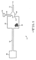
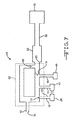
図1は、本発明に係る粒子状治療薬送達装置10の一実施形態を示す略図である。送達装置10は、患者と通気的に接続できる患者側末端16を有する呼吸ガスチャネル13を有している。呼吸ガスチャネル13は、患者の気管内に挿入できる気管内チューブを有している。
FIG. 1 is a schematic diagram illustrating one embodiment of a particulate
送達装置10は、呼吸ガスチャネル13と通気的に連通している粒子状治療薬チャネル19を有している。エアロゾル発生器28は、粒子状治療薬チャネル19と通気的に連通するように設置されている。エアロゾル発生器28は、例えば、ジェット噴霧器あるいは超音波ネブライザーのような噴霧器である。呼吸ガスチャネル13は、混合チャンバー29(治療薬を分散し、呼吸ガスと混合する場所となる)を有している。
The
スクラバーハウジング22は、呼吸ガスチャネル13と通気的に連通している。スクラバーハウジング22は、電荷が発達しないように導電性物質を含んでおり、それによって、治療薬がスクラバーハウジング22に集められる。スクラバーハウジング22は、呼吸ガスチャネル13から呼気を受け取る呼気口25を有している。スクラバー物質26は、スクラバーハウジング22内に配置されている。スクラバー物質26の一部を図1に示す。スクラバー物質26は、呼気口25を経由した呼気を受けるために、スクラバーハウジング内に置かれている。スクラバー物質26として、ソーダ石灰を用いることができる。スクラバー物質26は、呼気から二酸化炭素を除去して処理後の気体を提供するために置かれている(処理後の気体は呼吸ガスチャネル13に供給される)。
The
図1は、粒子状治療薬チャネル19が、呼吸ガスチャネル13上の薬剤送出場所31と通気的に連通している様子を示している。薬剤送出場所31は、呼気口25から患者側末端16へ至るガスの通常の流れが通る場所に設けられている。
FIG. 1 shows the particulate
ベンチレーター85は、呼吸ガスチャネル13と通気的に連通するように設置されている。ここで、「ベンチレーター」とは、呼吸ガスを呼吸ガスチャネル13を経て患者へ送り込むための力を供給する装置を含む意味で用いられる。この定義は、一般に「ベンチレーター」と呼ばれる装置だけでなく、一般に「レスピレータ」と呼ばれる装置も含むことを意図している。ベンチレーター85の一部は、フレキシブルな振動板あるいはアコーディオン状のスリーブ等であり、呼吸ガスチャネル13内の治療薬を気管支内に送り込むために動く。
The
ベンチレーター85は、呼気貯蔵所52と通気的に連通している。呼気貯蔵所52は、患者の将来の吸気のために、治療薬を含む気体を蓄える場所として役立つ。
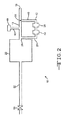
図2は、呼吸ガスチャネル13からエアロゾル発生器28に至る第一チャネル37、及びエアロゾル発生器28から呼吸ガスチャネル13に至る第二チャネル40を有する送達装置10の一実施形態の概略図である。ポンプ43は、ガスを、呼吸ガスチャネル13からエアロゾル発生器28を通って、呼吸ガスチャネル13に戻るように移動させるため、この回路内に配置されている。
FIG. 2 is a schematic diagram of one embodiment of the
図2に示す実施形態には、呼気貯蔵所52の一端にあるアウトレット・バルブ55が存在する。アウトレット・バルブ55は、送達装置10からの治療薬のロスを減じるのに役立つ。アウトレット・バルブ55は、呼気時にガスを放出するために配置されている。アウトレット・バルブ55は、送達装置10内の圧力を許容域内に保つために設置されている。
In the embodiment shown in FIG. 2, there is an
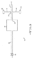
図3は、本発明に係る送達装置10の別の実施形態の概略図である。この送達装置10では、バイアス・ガスチャネル46は呼吸ガスチャネル13と通気的に連通して設置されている。バイアス・ガス源49は、バイアス・ガスを、バイアス・ガスチャネル46を経て呼吸ガスチャネル13に供給する。バイアス・ガスの目的は、患者にとって望ましい酸素分圧を維持することである。
FIG. 3 is a schematic view of another embodiment of a
図4は、図3とは異なる位置に配置されたバイアス・ガス源49とバイアス・ガスチャネル46を示す。バイアス・ガスチャネル46は、図に示すように、上記と同様、呼気貯蔵所52と通気的に連通している。
FIG. 4 shows the
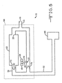
図5は、スクラバーハウジング22が処理ガス口73を有している送達装置であって、処理ガス口73と呼吸ガスチャネル13との間を通気的に接続するために配置されている処理ガスチャネル76を有する送達装置10の概略図である。エリア88は、装置10における、「循環回路」と言われる部分を示している。このように呼ばれるのは、気体が循環方式で流れる通路だからである。吸気逆止め弁79は、循環回路88内(例えば、処理ガスチャネル76の端部付近)に配置されている。吸気逆止め弁79は、吸気時は開き、呼気時は閉じるように構成されている。吸気逆止め弁79は、不完全な浄化ガスの呼吸ガスチャネルへの再侵入(吸気時に発生しうる)を防止するため、呼吸ガスチャネル13内の粒子状治療薬が、吸気時に主に患者側末端16のほうへ流れて行くようにするため、処理後の気体が呼気口25のほうへ流れて行かないようにするため、呼気時に呼気がスクラバーハウジング22を迂回することを妨げるため、あるいはこれらのいずれかの組合せのために配置され構成されている。
FIG. 5 shows a delivery device in which the
呼気逆止め弁82は、循環回路88内に設置されている。呼気逆止め弁82は、呼気時は開き、吸気時は閉じるようになっている。呼気逆止め弁82は、不完全な浄化ガスの呼吸ガスチャネルへの再侵入を防ぐため(吸気時に発生しうる)、呼吸ガスチャネル13内の粒子状治療薬が吸気時に主に患者側末端16のほうへ流れるようにするため、処理後の気体が呼気口25に流れていかないようにするため、呼気時に呼気がスクラバーハウジング22を迂回しないようにするため、あるいはこれらのいずれかの組合せのために配置され構成されている。
The exhalation check valve 82 is installed in the
図6および図7は、これまでに説明した特徴を含む、本発明に係る送達装置10の他の実施形態の概略図である。図6および図7において、スクラバーハウジング22は、循環回路88内に配置されていない。これらの実施形態では、呼気は呼気時に呼気口25を経てスクラバーハウジング22に入り、処理後の気体は吸気時に呼気口25を経てスクラバーハウジング22から出ていく。図5に示した送達装置10と同様、図6および図7の送達装置10は、吸気時に発生しうる、不完全な浄化ガスの呼吸ガスチャネルへの再侵入を防ぐため、呼吸ガスチャネル13内の粒子状治療薬が吸気時に主に患者側末端16のほうへ流れて行くようにするため、処理後の気体が呼気口25の方へ流れて行かないようにするため、あるいはこれらのいずれかの組合せのために設置され構成された吸気逆止め弁79及び呼気逆止め弁82を有する。
6 and 7 are schematic views of another embodiment of the
本発明に係る方法は、粒子状治療薬を送達することを可能にする。図8は、その一実施態様のブロック図である。この方法では、気管支を有する患者(100)の気管支に、粒子状治療薬が供給される(103)。103では、気管支に供給されていくガス中に噴霧することによって、治療薬を供給することができる。二酸化炭素スクラバーは、気管支と通気的に連通するように設置される(106)。気管支からの呼気をスクラバーに供給し(109)、スクラバーを通して処理後の気体を得る(112)。処理後の気体は、呼気より低いCO2分圧を有すると考えられる。処理後の気体はその後気管支に供給される(115)。ベンチレーターを用意し、ベンチレーターの一部を動かして、治療薬を気管支内に送達することもできる。ベンチレーターは、患者と通気的に連通していてもしていなくてもよい。 The method according to the invention makes it possible to deliver a particulate therapeutic agent. FIG. 8 is a block diagram of one embodiment thereof. In this method, a particulate therapeutic is delivered to the bronchi of a patient (100) with bronchi (103). At 103, the therapeutic agent can be delivered by spraying into the gas being supplied to the bronchi. A carbon dioxide scrubber is placed in air communication with the bronchi (106). Exhaled air from the bronchi is supplied to the scrubber (109), and the processed gas is obtained through the scrubber (112). The treated gas is believed to have a lower CO 2 partial pressure than exhalation. The treated gas is then supplied to the bronchi (115). A ventilator can be provided and a portion of the ventilator can be moved to deliver the therapeutic agent into the bronchi. The ventilator may or may not be in air communication with the patient.
当該方法において、低酸素症を防ぐために、酸素割合を高めたバイアス流を供給し、一方で、呼気の浪費を最小限にするために、バイアス流の速度を低く保ってもよい。バイアス(フレッシュガス)流を通常換気量の10%とした場合、呼気流の約6%のみが本発明に係る循環回路から抜け出、残りは再呼吸されると考えられる。粒子状治療薬を呼気時に加えれば、呼気時に投与された治療薬のほとんどが次の呼吸時に吸い込まれ、それによって、呼気相の間の治療薬の無駄が解消されると考えられる。低酸素症及び高炭酸血症は回避される。特別な呼吸技術は必要でなく、患者は快適に過ごすことができる。 In the method, a bias flow with an increased oxygen fraction may be provided to prevent hypoxia, while the bias flow rate may be kept low to minimize expiratory waste. If the bias (fresh gas) flow is 10% of the normal ventilation, only about 6% of the expiratory flow will escape from the circulation circuit according to the present invention and the rest will be rebreathed. If the particulate therapeutic agent is added during expiration, most of the therapeutic agent administered during expiration will be inhaled during the next breath, thereby eliminating the waste of therapeutic agent during the expiration phase. Hypoxia and hypercapnia are avoided. Special breathing techniques are not required and the patient can spend comfortably.
本発明に係る方法では、再呼吸された治療薬は、吸気時に患者に送達される治療薬の濃度を増加させるために使用されるので、治療薬の送達及び取込の両方が増加する。これは、ただ単に麻酔の最中に揮発性薬剤及び気体を節約するために再呼吸が行われる従来技術の方法とは区別される。従来技術における麻酔薬投与では、循環回路の麻酔薬濃度は、麻酔のために望ましい肺胞気濃度を達成するために調節されている。このような麻酔薬投与では、低く保たれたバイアス流は、麻酔に必要とされる麻酔薬の量を減じている(肺による取込を増加させるために治療薬濃度を上昇させる目的で使用されていない)。 In the method according to the invention, the rebreathed therapeutic agent is used to increase the concentration of therapeutic agent delivered to the patient during inspiration, thus increasing both therapeutic agent delivery and uptake. This is in contrast to prior art methods, where rebreathing is simply performed to save volatile drugs and gases during anesthesia. In prior art anesthetic administration, the anesthetic concentration in the circulatory circuit is adjusted to achieve the desired alveolar concentration for anesthesia. In such anesthetic administration, a low bias flow reduces the amount of anesthetic needed for anesthesia (used to increase therapeutic agent concentration to increase lung uptake. Not)
本発明は、スクラバーあるいは再呼吸回路が多量の治療薬を除去しない限り、肺が所定量の治療薬を吸収する機会を、実質的に増加させることができる。再呼吸回路が微粒子状のエアロゾルとして投与された治療薬を除去する程度を見極めるために、ソーダ石灰の循環回路からの、微粒子状のエアロゾルであるタバコの煙の損失率を測定した。粒子状の煙の11〜13%のみが、ほぼ一呼吸サイクルの持続時間に該当する3秒間で、回路によって消費された。再呼吸回路による微粒子状エアロゾルの除去率は低いと推定されるので、二酸化炭素スクラバーを通る粒子状治療薬を再呼吸することにより、実質的な効率は増加するはずである。さらに、再呼吸回路内に煙を投与することにより、肺モデルに送られた空気中の煙の濃度は7倍に増加した。 The present invention can substantially increase the opportunity for the lungs to absorb a given amount of therapeutic agent unless the scrubber or rebreathing circuit removes a large amount of therapeutic agent. In order to determine the extent to which the rebreathing circuit removes the therapeutic agent administered as a particulate aerosol, the loss rate of tobacco smoke, a particulate aerosol, from the soda-lime circulation circuit was measured. Only 11-13% of the particulate smoke was consumed by the circuit in 3 seconds, corresponding to the duration of almost one breathing cycle. Since the rate of particulate aerosol removal by the rebreathing circuit is estimated to be low, rebreathing the particulate therapeutic agent through the carbon dioxide scrubber should increase substantial efficiency. Furthermore, administering smoke into the rebreathing circuit increased the concentration of smoke in the air sent to the lung model by a factor of seven.
本発明に係る方法は、患者の協力をほとんどあるいは全く要求しない。理論上、本発明に係る方法は、従来技術の治療薬送達方法より効率が高く、それゆえコスト効率もより優れている。さらに、本発明に係る方法は、自発呼吸している患者および人工呼吸器を装着している患者の両方における長期投薬時に使用することができる。 The method according to the invention requires little or no patient cooperation. Theoretically, the method according to the present invention is more efficient than the prior art therapeutic drug delivery methods and is therefore more cost effective. Furthermore, the method according to the invention can be used during long-term dosing in both patients who are spontaneously breathing and patients who are wearing ventilators.
非再呼吸エアロゾル投与は、室内の空気を呼吸している患者にとって安全である。しかしながら、本発明に係る再呼吸方法は、高い割合の吸入酸素なしでは安全に使用されないかもしれない。それゆえ、この方法は、酸素あるいは酸素割合の高い混合ガスを入手できる患者に限定される可能性がある。 Non-rebreathing aerosol administration is safe for patients breathing room air. However, the rebreathing method according to the present invention may not be used safely without a high proportion of inhaled oxygen. Therefore, this method may be limited to patients who have access to oxygen or a gas mixture with a high oxygen percentage.
本発明は、一以上の特定の実施形態に関して記述されているが、本発明の他の実施形態が、本発明の精神および範囲から逸脱することなく存在することが理解されるであろう。それ故、本発明は、添付の特許請求の範囲及びその適切な解釈によってのみ限定されるとみなされる。 Although the invention has been described with respect to one or more specific embodiments, it will be understood that other embodiments of the invention exist without departing from the spirit and scope of the invention. Therefore, the present invention is deemed limited only by the appended claims and appropriate interpretation thereof.
Claims (19)
前記呼吸ガスチャネルと通気的に連通している粒子状治療薬チャネル、
前記呼吸ガスチャネルと通気的に連通し、且つ該呼吸ガスチャネルから呼気を受け取るための呼気口を有しているスクラバーハウジング、及び
該呼気口を経由した呼気を受け取って二酸化炭素を除去し、前記呼吸ガスチャネルに処理後の気体を供給するために前記ハウジング内に配置されている、スクラバー物質
とを有する粒子状治療薬送達装置。 A breathing gas channel having a patient end that can be ventilated with the patient;
A particulate therapeutic channel in air communication with the respiratory gas channel;
A scrubber housing in air communication with the breathing gas channel and having an exhalation port for receiving exhalation from the breathing gas channel; and receiving exhalation via the exhalation port to remove carbon dioxide; A particulate therapeutic agent delivery device having a scrubber material disposed within the housing for supplying treated gas to a respiratory gas channel.
前記送達装置がさらに、前記スクラバーハウジングを経由したガスが前記呼吸ガスチャネルに送達されるように、前記処理ガス口と前記呼吸ガスチャネルの間を通気的に連通する処理ガスチャネルを有する、請求項1に記載の送達装置。 The scrubber housing has a process gas port;
The delivery device further comprises a process gas channel in air communication between the process gas port and the breathing gas channel such that gas via the scrubber housing is delivered to the breathing gas channel. 2. The delivery device according to 1.
粒子状治療薬を気管支に供給し、
気管支と通気的に連通する二酸化炭素スクラバーを準備し、
気管支から前記スクラバーに呼気を供給し、
呼気を前記スクラバーに通して処理後の気体を得、
該処理後の気体を気管支に供給することを含む、
粒子状治療薬を送達する方法。 For patients with bronchi
Supplying particulate therapeutics to the bronchi,
Prepare a carbon dioxide scrubber that is in air communication with the bronchi,
Supplying exhaled breath from the bronchi to the scrubber;
Pass exhalation through the scrubber to obtain the treated gas,
Providing the treated gas to the bronchi,
A method of delivering a particulate therapeutic.
治療薬を気管支内に送り込むために該ベンチレーターを動かすことを含む、
請求項15に記載の方法。 In addition, prepare a ventilator,
Moving the ventilator to deliver a therapeutic agent into the bronchi,
The method of claim 15.
Applications Claiming Priority (2)
| Application Number | Priority Date | Filing Date | Title |
|---|---|---|---|
| US39231402P | 2002-06-28 | 2002-06-28 | |
| PCT/US2003/020532 WO2004002390A2 (en) | 2002-06-28 | 2003-06-30 | Therapeutic agent delivery device and method |
Publications (1)
| Publication Number | Publication Date |
|---|---|
| JP2005531373A true JP2005531373A (en) | 2005-10-20 |
Family
ID=30000843
Family Applications (1)
| Application Number | Title | Priority Date | Filing Date |
|---|---|---|---|
| JP2004518098A Pending JP2005531373A (en) | 2002-06-28 | 2003-06-30 | Therapeutic drug delivery apparatus and method |
Country Status (9)
| Country | Link |
|---|---|
| US (1) | US7367335B2 (en) |
| EP (2) | EP3335752A1 (en) |
| JP (1) | JP2005531373A (en) |
| AU (1) | AU2003247834A1 (en) |
| CA (1) | CA2490857C (en) |
| ES (1) | ES2651342T3 (en) |
| HK (1) | HK1254943A1 (en) |
| MX (1) | MXPA05000223A (en) |
| WO (1) | WO2004002390A2 (en) |
Families Citing this family (19)
| Publication number | Priority date | Publication date | Assignee | Title |
|---|---|---|---|---|
| US7089933B2 (en) * | 2002-10-25 | 2006-08-15 | Hamilton Sundstrand | CO2 sorbent for inhalation drug therapy system |
| US7849853B2 (en) * | 2003-02-11 | 2010-12-14 | Trudell Medical International | Ventilator circuit and the method for the use thereof |
| US8028697B2 (en) * | 2005-04-28 | 2011-10-04 | Trudell Medical International | Ventilator circuit and method for the use thereof |
| KR102103541B1 (en) * | 2005-08-12 | 2020-04-23 | 캄브리오스 필름 솔루션스 코포레이션 | Nanowires-based transparent conductors |
| WO2007133837A2 (en) * | 2006-05-12 | 2007-11-22 | Advanced Technology Materials, Inc. | Low temperature deposition of phase change memory materials |
| JP5307715B2 (en) | 2006-08-21 | 2013-10-02 | トルーデル メディカル インターナショナル | Respiratory muscle endurance training equipment |
| FR2906710B1 (en) * | 2006-10-05 | 2008-12-12 | Equip Veterinaire Minerve Sa | SAFETY ANESTHESIA DEVICE FOR MEDICAL SAMPLES CARRIED OUT WITH HIGH CADENCE ON SMALL LABORATORY ANIMALS |
| FR2915106B3 (en) * | 2007-04-18 | 2009-03-06 | Diffusion Tech Francaise Sarl | PNEUMATIC NEBULIZER DEVICE OF AEROSOLS. |
| US8151794B2 (en) | 2007-04-24 | 2012-04-10 | Trudell Medical International | Aerosol delivery system |
| WO2008138014A1 (en) * | 2007-05-08 | 2008-11-13 | The Research Foundation Of State University Of New York | Breathing-gas delivery system with exhaust gas filter body and method of operating a breathing-gas delivery system |
| EP2008679A1 (en) * | 2007-06-28 | 2008-12-31 | General Electric Company | Patient breathing system |
| WO2009105515A2 (en) | 2008-02-21 | 2009-08-27 | Trudell Medical International | Respiratory muscle endurance training device and method for the use thereof |
| WO2010036816A1 (en) | 2008-09-25 | 2010-04-01 | Nellcor Puritan Bennett Llc | Inversion-based feed-forward compensation of inspiratory trigger dynamics in medical ventilators |
| US8596265B2 (en) | 2008-10-22 | 2013-12-03 | Trudell Medical International | Modular aerosol delivery system |
| US20120318263A1 (en) * | 2011-06-16 | 2012-12-20 | General Electric Company | Anesthesia vaporizer system and method |
| SG10201601960SA (en) * | 2011-09-14 | 2016-04-28 | American Regenerative Technologies Llc | Inhalation systems, breathing apparatuses, and methods |
| WO2013166430A2 (en) * | 2012-05-04 | 2013-11-07 | Trustees Of The University Of Pennsylvania | System for delivery of gaseous imaging contrast agents and methods for using same |
| EP4186548A1 (en) | 2015-04-02 | 2023-05-31 | Hill-Rom Services PTE. LTD. | Mask leakage detection for a respiratory device |
| CA2990545A1 (en) * | 2015-07-06 | 2017-01-12 | Joel Ironstone | Oxygen rebreathing apparatus and method for using the same |
Family Cites Families (35)
| Publication number | Priority date | Publication date | Assignee | Title |
|---|---|---|---|---|
| US1693730A (en) * | 1925-11-16 | 1928-12-04 | Elfriede Drager | Breathing apparatus particularly for administering anesthetics |
| DE1251913B (en) | 1965-03-20 | 1967-10-12 | Dragerwerk Hemr & Bernh Drager, Lübeck | Ventilation device |
| US4127121A (en) * | 1976-09-17 | 1978-11-28 | University Of Utah | Oxygen and anesthesia delivery and monitoring device |
| US4354536A (en) | 1980-04-09 | 1982-10-19 | Jack Moss | Gasoline dispensing nozzle |
| US4466433A (en) | 1981-12-04 | 1984-08-21 | Minnesota Mining And Manufacturing Company | Overpressure relief system |
| JPS59101159A (en) | 1982-11-30 | 1984-06-11 | 泉工医科工業株式会社 | Artificial respirator having double-barreled jet pipe |
| US4821709A (en) | 1983-08-01 | 1989-04-18 | Sensormedics Corporation | High frequency ventilator and method |
| DE3429389C1 (en) | 1984-08-09 | 1986-03-13 | Brugger, Inge, geb. Ritzau, 8130 Starnberg | Inhaler |
| SE451051B (en) | 1985-03-26 | 1987-08-31 | Icor Ab | DEVICE FOR Saturation of a person's acid uptake |
| US4719910A (en) | 1985-04-29 | 1988-01-19 | Jensen Robert L | Oscillating ventilator and method |
| US4805612A (en) | 1985-09-13 | 1989-02-21 | Sensormedics Corporation | High frequency ventilation |
| US4879996A (en) | 1987-01-13 | 1989-11-14 | Harwood Jr Van N | Closed circuit breathing apparatus |
| SE8700977D0 (en) * | 1987-03-09 | 1987-03-09 | Olof Werner | UNIT WHICH SEPARATELY SEPARATES THE GAS CONTENT IN THE DRIVE CIRCUIT AND THE RECEIVER CIRCUIT BUT ONLY ALLOWS GAS PIPE IN THE BAD DIRECTIONS (OPEN SEPARATION) |
| US5322057A (en) * | 1987-07-08 | 1994-06-21 | Vortran Medical Technology, Inc. | Intermittent signal actuated nebulizer synchronized to operate in the exhalation phase, and its method of use |
| JPS6449541A (en) | 1987-08-19 | 1989-02-27 | Anzai Sogyo Co Ltd | Xenon gas inhalation system |
| US5092326A (en) | 1987-11-19 | 1992-03-03 | Winn Bryan D | Apparatus and method for a ventilator system |
| US4951659A (en) | 1988-11-04 | 1990-08-28 | Automatic Liquid Packaging, Inc. | Nebulizer with cooperating disengageable on-line heater |
| SE465497B (en) | 1989-11-24 | 1991-09-23 | Minco Ab | DEVICE FOR STUDYING A PERSON'S LUNG FUNCTION |
| US5165398A (en) | 1989-12-08 | 1992-11-24 | Bird F M | Ventilator and oscillator for use therewith and method |
| AU657726B2 (en) * | 1990-12-05 | 1995-03-23 | General Hospital Corporation, The | Devices for treating pulmonary vasoconstriction and asthma |
| US5570683A (en) * | 1990-12-05 | 1996-11-05 | The General Hospital Corporation | Methods and devices for treating pulmonary vasoconstriction and asthma |
| US5186166A (en) * | 1992-03-04 | 1993-02-16 | Riggs John H | Powder nebulizer apparatus and method of nebulization |
| US5307794A (en) | 1992-04-01 | 1994-05-03 | Sensormedics Corporation | Oscillating ventilator apparatus and method and patient isolation apparatus |
| US5335650A (en) * | 1992-10-13 | 1994-08-09 | Temple University - Of The Commonwealth System Of Higher Education | Process control for liquid ventilation and related procedures |
| US5555880A (en) | 1994-01-31 | 1996-09-17 | Southwest Research Institute | High frequency oscillatory ventilator and respiratory measurement system |
| US5590651A (en) * | 1995-01-17 | 1997-01-07 | Temple University - Of The Commonwealth System Of Higher Education | Breathable liquid elimination analysis |
| SE9500175L (en) | 1995-01-19 | 1996-07-20 | Siemens Elema Ab | Method and apparatus for identifying at least one anesthetic in an anesthetic device |
| US5823180A (en) * | 1995-04-03 | 1998-10-20 | The General Hospital Corporation | Methods for treating pulmonary vasoconstriction and asthma |
| SE9503141D0 (en) * | 1995-09-12 | 1995-09-12 | Siemens Elema Ab | Anesthesia apparatus |
| RU2072241C1 (en) * | 1995-09-20 | 1997-01-27 | Панина Елена Владимировна | Method and device for preparing inhalation gas mixture |
| SE9503665L (en) | 1995-10-19 | 1997-04-20 | Siemens Elema Ab | Anesthesia System |
| US6041777A (en) * | 1995-12-01 | 2000-03-28 | Alliance Pharmaceutical Corp. | Methods and apparatus for closed-circuit ventilation therapy |
| JP3898251B2 (en) | 1996-03-28 | 2007-03-28 | スズキ株式会社 | Diaphragm neutral position controller for ventilator |
| US6095135A (en) * | 1998-07-10 | 2000-08-01 | Enternet Medical, Inc. | Apparatus for providing benefits to respiratory gases |
| SE9902627D0 (en) * | 1999-07-08 | 1999-07-08 | Siemens Elema Ab | Medical nebulizer |
-
2003
- 2003-06-30 US US10/610,210 patent/US7367335B2/en not_active Expired - Fee Related
- 2003-06-30 CA CA2490857A patent/CA2490857C/en not_active Expired - Fee Related
- 2003-06-30 AU AU2003247834A patent/AU2003247834A1/en not_active Abandoned
- 2003-06-30 ES ES03762224.8T patent/ES2651342T3/en not_active Expired - Lifetime
- 2003-06-30 JP JP2004518098A patent/JP2005531373A/en active Pending
- 2003-06-30 WO PCT/US2003/020532 patent/WO2004002390A2/en active Application Filing
- 2003-06-30 MX MXPA05000223A patent/MXPA05000223A/en active IP Right Grant
- 2003-06-30 EP EP17183408.8A patent/EP3335752A1/en not_active Withdrawn
- 2003-06-30 EP EP03762224.8A patent/EP1558312B1/en not_active Expired - Lifetime
-
2018
- 2018-11-02 HK HK18114046.5A patent/HK1254943A1/en unknown
Also Published As
| Publication number | Publication date |
|---|---|
| US7367335B2 (en) | 2008-05-06 |
| CA2490857C (en) | 2011-08-30 |
| CA2490857A1 (en) | 2004-01-08 |
| AU2003247834A1 (en) | 2004-01-19 |
| US20040003808A1 (en) | 2004-01-08 |
| EP1558312A2 (en) | 2005-08-03 |
| HK1254943A1 (en) | 2019-08-02 |
| MXPA05000223A (en) | 2005-07-15 |
| ES2651342T3 (en) | 2018-01-25 |
| EP1558312B1 (en) | 2017-08-09 |
| WO2004002390A3 (en) | 2004-04-29 |
| EP1558312A4 (en) | 2010-01-20 |
| EP3335752A1 (en) | 2018-06-20 |
| AU2003247834A8 (en) | 2004-01-19 |
| WO2004002390A2 (en) | 2004-01-08 |
Similar Documents
| Publication | Publication Date | Title |
|---|---|---|
| JP2005531373A (en) | Therapeutic drug delivery apparatus and method | |
| US20200261671A1 (en) | Gas therapy system | |
| US5690097A (en) | Combination anesthetic mask and oxygen transport system | |
| US7946291B2 (en) | Ventilation systems and methods employing aerosol generators | |
| JP3802929B2 (en) | Nebulizer respiratory circulator | |
| US7448376B2 (en) | Medication delivery device and method | |
| JP6640832B2 (en) | Positive pressure inhaler for drug delivery | |
| US20030145853A1 (en) | Expiration- dependent gas dosage | |
| JP2000225191A (en) | Respiratory mask for gas feed for medical treatment | |
| JPH11508788A (en) | Ventilator device | |
| JP2000501306A (en) | Method and apparatus for closed circuit ventilation therapy | |
| WO1999052580A1 (en) | Automatic control method for supplying anaesthetic to a low flow-type closed circuit | |
| US7533669B2 (en) | Gas delivery system and method | |
| JP2004016824A (en) | Gas supplier | |
| CA2540531C (en) | Device and method of partially separating gas | |
| JPH08317981A (en) | Oxygen supply apparatus regulatable of oxygen concentration to spontaneously respirable patient using tracheal tube or mask | |
| JP4152010B2 (en) | Intermittent positive pressure breathing assist device | |
| JP2005342353A (en) | Inhalator and inhalation apparatus, or method for applying inhalator | |
| CN218338785U (en) | Anti-drop nebeulizer mask | |
| CN108671351A (en) | A kind of department of anesthesia's anesthesiaing system with humidification function | |
| RU2303472C1 (en) | Method and breathing mask for gas medium cleaning in pressurized object | |
| JP2000102617A (en) | Positive pressure artificial respiratory auxiliary apparatus | |
| WO2020120212A1 (en) | Humidification and mucus mobilization with an on-demand humidifier | |
| RU2323754C1 (en) | Respiratory apparatus to perform cleaning of gas medium in hermetic object | |
| BARAKA et al. | Automatic jet ventilation in children anaesthetized by the T‐piece circuit |
Legal Events
| Date | Code | Title | Description |
|---|---|---|---|
| A621 | Written request for application examination |
Free format text: JAPANESE INTERMEDIATE CODE: A621 Effective date: 20060630 |
|
| RD02 | Notification of acceptance of power of attorney |
Free format text: JAPANESE INTERMEDIATE CODE: A7422 Effective date: 20061003 |
|
| A521 | Written amendment |
Free format text: JAPANESE INTERMEDIATE CODE: A821 Effective date: 20061003 |
|
| A131 | Notification of reasons for refusal |
Free format text: JAPANESE INTERMEDIATE CODE: A131 Effective date: 20090610 |
|
| A601 | Written request for extension of time |
Free format text: JAPANESE INTERMEDIATE CODE: A601 Effective date: 20090909 |
|
| A602 | Written permission of extension of time |
Free format text: JAPANESE INTERMEDIATE CODE: A602 Effective date: 20090916 |
|
| A601 | Written request for extension of time |
Free format text: JAPANESE INTERMEDIATE CODE: A601 Effective date: 20091013 |
|
| A602 | Written permission of extension of time |
Free format text: JAPANESE INTERMEDIATE CODE: A602 Effective date: 20091020 |
|
| A601 | Written request for extension of time |
Free format text: JAPANESE INTERMEDIATE CODE: A601 Effective date: 20091110 |
|
| A602 | Written permission of extension of time |
Free format text: JAPANESE INTERMEDIATE CODE: A602 Effective date: 20091117 |
|
| RD04 | Notification of resignation of power of attorney |
Free format text: JAPANESE INTERMEDIATE CODE: A7424 Effective date: 20091216 |
|
| A02 | Decision of refusal |
Free format text: JAPANESE INTERMEDIATE CODE: A02 Effective date: 20100224 |