JP2005525518A - Static seal between bearing ring and shaft - Google Patents
Static seal between bearing ring and shaft Download PDFInfo
- Publication number
- JP2005525518A JP2005525518A JP2004503817A JP2004503817A JP2005525518A JP 2005525518 A JP2005525518 A JP 2005525518A JP 2004503817 A JP2004503817 A JP 2004503817A JP 2004503817 A JP2004503817 A JP 2004503817A JP 2005525518 A JP2005525518 A JP 2005525518A
- Authority
- JP
- Japan
- Prior art keywords
- seal
- bearing
- annular
- annular recess
- elastic
- Prior art date
- Legal status (The legal status is an assumption and is not a legal conclusion. Google has not performed a legal analysis and makes no representation as to the accuracy of the status listed.)
- Pending
Links
Images
Classifications
-
- F—MECHANICAL ENGINEERING; LIGHTING; HEATING; WEAPONS; BLASTING
- F16—ENGINEERING ELEMENTS AND UNITS; GENERAL MEASURES FOR PRODUCING AND MAINTAINING EFFECTIVE FUNCTIONING OF MACHINES OR INSTALLATIONS; THERMAL INSULATION IN GENERAL
- F16C—SHAFTS; FLEXIBLE SHAFTS; ELEMENTS OR CRANKSHAFT MECHANISMS; ROTARY BODIES OTHER THAN GEARING ELEMENTS; BEARINGS
- F16C33/00—Parts of bearings; Special methods for making bearings or parts thereof
- F16C33/72—Sealings
- F16C33/76—Sealings of ball or roller bearings
- F16C33/768—Sealings of ball or roller bearings between relatively stationary parts, i.e. static seals
-
- B—PERFORMING OPERATIONS; TRANSPORTING
- B60—VEHICLES IN GENERAL
- B60B—VEHICLE WHEELS; CASTORS; AXLES FOR WHEELS OR CASTORS; INCREASING WHEEL ADHESION
- B60B27/00—Hubs
-
- F—MECHANICAL ENGINEERING; LIGHTING; HEATING; WEAPONS; BLASTING
- F16—ENGINEERING ELEMENTS AND UNITS; GENERAL MEASURES FOR PRODUCING AND MAINTAINING EFFECTIVE FUNCTIONING OF MACHINES OR INSTALLATIONS; THERMAL INSULATION IN GENERAL
- F16J—PISTONS; CYLINDERS; SEALINGS
- F16J15/00—Sealings
- F16J15/02—Sealings between relatively-stationary surfaces
-
- F—MECHANICAL ENGINEERING; LIGHTING; HEATING; WEAPONS; BLASTING
- F16—ENGINEERING ELEMENTS AND UNITS; GENERAL MEASURES FOR PRODUCING AND MAINTAINING EFFECTIVE FUNCTIONING OF MACHINES OR INSTALLATIONS; THERMAL INSULATION IN GENERAL
- F16C—SHAFTS; FLEXIBLE SHAFTS; ELEMENTS OR CRANKSHAFT MECHANISMS; ROTARY BODIES OTHER THAN GEARING ELEMENTS; BEARINGS
- F16C19/00—Bearings with rolling contact, for exclusively rotary movement
- F16C19/22—Bearings with rolling contact, for exclusively rotary movement with bearing rollers essentially of the same size in one or more circular rows, e.g. needle bearings
- F16C19/34—Bearings with rolling contact, for exclusively rotary movement with bearing rollers essentially of the same size in one or more circular rows, e.g. needle bearings for both radial and axial load
- F16C19/36—Bearings with rolling contact, for exclusively rotary movement with bearing rollers essentially of the same size in one or more circular rows, e.g. needle bearings for both radial and axial load with a single row of rollers
- F16C19/364—Bearings with rolling contact, for exclusively rotary movement with bearing rollers essentially of the same size in one or more circular rows, e.g. needle bearings for both radial and axial load with a single row of rollers with tapered rollers, i.e. rollers having essentially the shape of a truncated cone
-
- F—MECHANICAL ENGINEERING; LIGHTING; HEATING; WEAPONS; BLASTING
- F16—ENGINEERING ELEMENTS AND UNITS; GENERAL MEASURES FOR PRODUCING AND MAINTAINING EFFECTIVE FUNCTIONING OF MACHINES OR INSTALLATIONS; THERMAL INSULATION IN GENERAL
- F16C—SHAFTS; FLEXIBLE SHAFTS; ELEMENTS OR CRANKSHAFT MECHANISMS; ROTARY BODIES OTHER THAN GEARING ELEMENTS; BEARINGS
- F16C2326/00—Articles relating to transporting
- F16C2326/01—Parts of vehicles in general
- F16C2326/02—Wheel hubs or castors
Abstract
シールが提供されていて、シールは環状シール部材から延伸している突出部材を有しており、その突出部材は軸受に形成された環状凹部にスナップフィットするべく配置されている。弾性リップ(5)は、環状凹部の中に挿入される場合、従ってその中に保持されている場合弾性変形されている。軸受は凹部に隣接した保持リップ(15)を有していて、シールを取りはずそうとする場合シールの弾性リップは保持リップに対して接触し、従って取りはずしに必要な力を増大させている。A seal is provided, the seal having a protruding member extending from the annular seal member, the protruding member being positioned to snap fit into an annular recess formed in the bearing. The elastic lip (5) is elastically deformed when inserted into the annular recess and thus when held therein. The bearing has a retaining lip (15) adjacent to the recess so that when the seal is to be removed, the elastic lip of the seal contacts the retaining lip, thus increasing the force required for removal.
Description
本発明は軸受と、軸受を取り付けたホイールのアクスルシャフトのようなシャフトとの間のシールを提供するためのシールに関する。 The present invention relates to a seal for providing a seal between a bearing and a shaft, such as an axle shaft of a wheel to which the bearing is attached.
重いトラックドライブアクスル用のホイール端部配置において、ホイールは、アクスルシャフトをおおって差し込まれたころ軸受アセンブリを介してアクスルシャフトに取りつけられている。軸受アセンブリは、ローラが走行する内部円錐面によりベアリングコーンとして公知の内部軌道輪と外部軌道輪とからなる。内部ベアリングコーンはアクスルシャフトの小さくなった径の端部をおおって取りつけられていて、その背面はアクスルシャフトの環状ステップに対して係合している。シールがアクスルの潤滑油のリークを防止するべく背面とベアリングコーンとの間に提供されていて、その潤滑油は、軸受アセンブリの内側でアクスルシャフトと内部ベアリングコーンとの間の狭い半径方向のすき間にあって、ブレーキ装置コンポーネントのような自動車の他のコンポーネントを汚染するかもしれない。シールのさらなる目的は、反対方向における汚染物質特に水分の侵入を防止することである。そのような水分は、定期的な保修時におけるハブアセンブリの取りはずしに対して障害をもたらし、かつアクスル潤滑油を汚染する、アクスルシャフトとベアリングコーンとの間のインタフェースにおける腐蝕を引き起こすかも知れない。 In the wheel end arrangement for heavy truck drive axles, the wheel is attached to the axle shaft via a roller bearing assembly that is inserted over the axle shaft. The bearing assembly consists of an inner race and an outer race known as a bearing cone due to the inner conical surface on which the roller travels. The inner bearing cone is mounted over the reduced diameter end of the axle shaft and its back surface is engaged with the annular step of the axle shaft. A seal is provided between the rear surface and the bearing cone to prevent leakage of the axle lubricant, and the lubricant is located inside the bearing assembly between the axle shaft and the inner bearing cone. And may contaminate other components of the vehicle, such as brake system components. A further purpose of the seal is to prevent entry of contaminants, especially moisture, in the opposite direction. Such moisture may cause corrosion at the interface between the axle shaft and the bearing cone that interferes with removal of the hub assembly during regular maintenance and contaminates the axle lubricant.
通常、そのような用途でベアリングコーンの背面に提供されたシール装置は、標準のOリングシールエレメントからなり、そのエレメントは溝又は環状溝のどちらかに設定されていて、その溝はベアリングコーンの穴と背面との接続部における放射プロフィールに機械加工されており、その環状溝はベアリングコーンの背面又はアクスルシャフトの合口肩の面に機械加工されている。後者のタイプのシール装置の例は特許文献1に開示されている。 Usually, the sealing device provided at the back of the bearing cone for such applications consists of a standard O-ring seal element, which is set in either a groove or an annular groove, which groove is the bearing cone. Machined into a radial profile at the hole-back connection, the annular groove is machined into the back of the bearing cone or the abutment shoulder surface of the axle shaft. An example of the latter type of sealing device is disclosed in US Pat.
標準Oリングのいずれにおいても生じる問題は、シール装置を軸受アセンブリに取りつけようとする場合に生じる実際的な困難である。可能ではあるものの、シャフトと軸受装置との組立時にシール装置を正しい位置に取りつけ保持することを保証することは、労力を要し軸受アセンブリの製造コストに不相応なものとなっている。
従って、公知の構造により提供されるものに比較してシール装置の取りつけを利点的に達成できる、軸受と組合せたシールを提供する必要がある。 Accordingly, there is a need to provide a seal in combination with a bearing that can advantageously achieve the installation of a sealing device compared to that provided by known structures.
本発明は、シールと軸受との組合せ構造体を提供するものであって;該軸受が、内部に環状凹部と該環状凹部の外周囲における保持部分とを有しているボデーを具備していて、該シールが、該環状凹部に収容されるべく配置された環状シール部材を具備している該シールと軸受との組合せ構造体において;該環状シール部材が弾性突起と環状ボデー部分とを有していて、該弾性突起は該シールを該環状凹部に保持するために該保持部分と協働するべく配置されており、該環状ボデー部分は該弾性突起が延伸している外周面を有しており、さらに第一肩部分及び第二肩部分を有していて、該両肩部分の少なくとも一方が該シールと接触する表面を備えたシールを提供するようになっている。 The present invention provides a combined structure of a seal and a bearing, the bearing comprising a body having an annular recess therein and a retaining portion at the outer periphery of the annular recess. The seal and bearing combination structure, wherein the seal comprises an annular seal member arranged to be received in the annular recess; the annular seal member having an elastic protrusion and an annular body portion The elastic projection is arranged to cooperate with the holding portion to hold the seal in the annular recess, the annular body portion having an outer peripheral surface from which the elastic projection extends. And having a first shoulder portion and a second shoulder portion, wherein at least one of the shoulder portions provides a seal with a surface in contact with the seal.
好ましくは、該弾性突起が該環状凹部において該シールのスナップフィットを提供している。 Preferably, the resilient protrusion provides a snap fit of the seal in the annular recess.
該肩部分は、好ましくは該シールが肩を圧縮する場合、該シールが軸受とシャフトとの間に適切なシールを提供するようになっている。 The shoulder portion is preferably such that when the seal compresses the shoulder, the seal provides a suitable seal between the bearing and the shaft.
追加的にあるいは代りに該シールが内部撓性部材を備えている。該内部撓性部材は金属リングである。 Additionally or alternatively, the seal includes an internal flexible member. The internal flexible member is a metal ring.
該シールは、該弾性突起を通過する放射面に対して対称的である。 The seal is symmetric with respect to a radiation plane passing through the elastic protrusion.
好ましくは、該シールが成形ゴムで製作されている。 Preferably, the seal is made of molded rubber.
本発明の第二実施形態は、軸受に使用するためのシールを提供していて;環状部材を具備している該シールにおいて;該環状シール部材が弾性突起と環状ボデー部分とを有していて、該弾性突起は使用にあたって該シールを該環状凹部に保持するために該保持部分と協働するべく配置されており、該環状ボデー部分は該弾性突起が延伸している外周面を有しており、さらに第一肩部分及び第二肩部分を有していて、該両肩部分の少なくとも一方が該シールと接触する表面を備えたシールを提供するようになっている。 A second embodiment of the present invention provides a seal for use in a bearing; in the seal comprising an annular member; the annular seal member having an elastic protrusion and an annular body portion The elastic protrusion is arranged to cooperate with the holding portion to hold the seal in the annular recess in use, the annular body portion having an outer peripheral surface from which the elastic protrusion extends. And having a first shoulder portion and a second shoulder portion, wherein at least one of the shoulder portions provides a seal with a surface in contact with the seal.
好ましくは、該シールが、本発明の第一実施形態における組合せ構造体のシールの好適な実施形態一つあるいはそれ以上を備えている。 Preferably, the seal comprises one or more preferred embodiments of the seal of the combined structure in the first embodiment of the present invention.
本発明における実施形態が、例だけを用いて、添付図を参照して以下に説明されている。 Embodiments of the present invention are described below by way of example only and with reference to the accompanying drawings.
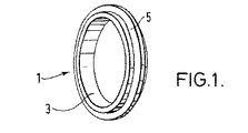
図1に図示するシール1は、内周面と外周面とを有している環状ボデー部分3を備えている。弾性リップ5がシール1の外周面から延伸している。シールは、好ましくは金属製の内部インサート周囲に形成された成形ゴムにより作られているけれども、周囲をゴムで形成するのに適切ないずれの剛構造体が使用されてもよい。
A seal 1 shown in FIG. 1 includes an
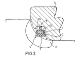
シール1の断面を図2に図示する。環状ボデー部分の断面はほぼ台形である。台形形状なので、環状ボデー部分3は内直径に向かって即ちシャフトの直近でより広い内周幅となっていて、二つの肩を有しており、一方の肩6が軸受とシャフトとの間のシールを提供している。他方の肩は、軸受に対してさらなるシールを形成していてもよい。環状ボデー部分3のより狭い外周幅は、シールが使用される場合環状ボデー部分3の狭い区画がシールに作用する圧縮力により環状凹部13にしっかりと設置されるように配置されている。さらに、図2は環状ボデー部分3における金属インサート7の位置を図示している。図2は、本発明による実施形態におけるベアリングコーン9とアクスルシャフト11とに使用されるシール1を図示している。ベアリングコーン9は、ベアリングコーン9の主ボデーとベアリングコーンの保持リップ15とにより形成された環状凹部13を有している。ベアリングコーン9をアクスルシャフト11に組立てる前に、シール1はベアリングコーン9の環状凹部13に挿入される。シール1を環状凹部13に設置するために、弾性リップ5がベアリングコーンの保持リップ15により復元可能に変形され、従ってシール1が環状凹部13に挿入されるようになっている。シールが環状凹部13に設置されると、弾性リップ5は初期形状に復元しようとするが、ベアリングコーンにおける環状凹部13のより小さな内径により復元を妨げられる。弾性リップ15にもたらされた変形は、軸受に対するさらなるシールを形成する。従って、シール1がベアリングコーン9に保持され、シャフトと軸受装置との組立が容易になっている。ベアリングコーン9における環状凹部13内部でのシール1のスナップフィット作用は、ベアリングコーンとシャフトアセンブリとの組立をさらに容易なものとしている。シール1を環状凹部13から取りはずす場合、弾性リップ5がベアリングコーン9の保持リップ15に対して接触し、従ってシールを挿入するのに必要な力と比較してより大きな引き抜き力を必要とされる。
A cross section of the seal 1 is illustrated in FIG. The cross section of the annular body portion is substantially trapezoidal. Due to the trapezoidal shape, the
シール1は、好ましくは放射面に対して対称的である。このことは、シール性能を損なうことなく適切ないずれの方向でシール1を環状凹部13に取付けることを可能にしている。 The seal 1 is preferably symmetrical with respect to the radiation surface. This makes it possible to attach the seal 1 to the annular recess 13 in any suitable direction without impairing the sealing performance.
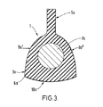
図3は、シール1の別の形状を図示している。図1及び2に図示するシールと同様に、シール1はボデー部分3aと、ボデー部分の外周から延伸している弾性リップ5aとを有している。シールは放射面に対して対称的である。円形の内部インサート7aがボデー部分3aの内部に設置されている。ボデー部分3aの断面はほぼベル形状であって、凸状の側面8a′及び8a″が弾性リップ5aから延伸していて、僅かに凸状の底面10aが二つの側面の間に延在している。側面8a′と底面10aとの交差部分が、図2に図示する台形状シール1と同様に肩6aを形成していて、肩6aは同一のシール機能となっている。他方の肩は軸受に対するさらなるシールを形成している。シール構造は他の適切なものであってもよい。
FIG. 3 illustrates another shape of the seal 1. Similar to the seal shown in FIGS. 1 and 2, the seal 1 includes a body portion 3a and an elastic lip 5a extending from the outer periphery of the body portion. The seal is symmetrical with respect to the radiation surface. A circular inner insert 7a is installed inside the body portion 3a. The cross section of the body portion 3a is substantially bell-shaped, with convex side surfaces 8a 'and 8a "extending from the elastic lip 5a, and a slightly
Claims (12)
該環状シール部材が弾性突起と環状ボデー部分とを有していて、該弾性突起は該シールを該環状凹部に保持するために該保持部分と協働するべく配置されており、該環状ボデー部分は該弾性突起が延伸している外周面を有しており、さらに第一肩部分及び第二肩部分を有していて、該両肩部分の少なくとも一方が該シールと接触する表面を備えたシールを提供するようになっている;
シールと軸受との組合せ構造体。 A combined structure of a seal and a bearing, the bearing comprising a body having an annular recess therein and a retaining portion at the outer periphery of the annular recess, the seal including the annular recess A seal-bearing combination structure comprising an annular seal member arranged to be received in the housing;
The annular seal member has an elastic projection and an annular body portion, the elastic projection being arranged to cooperate with the holding portion to hold the seal in the annular recess, the annular body portion Has an outer peripheral surface on which the elastic protrusion extends, and further includes a first shoulder portion and a second shoulder portion, and at least one of the shoulder portions has a surface in contact with the seal. Providing a seal;
Combination structure of seal and bearing.
該環状シール部材が弾性突起と環状ボデー部分とを有していて、該弾性突起は使用にあたって該シールを該環状凹部に保持するために該保持部分と協働するべく配置されており、該環状ボデー部分は該弾性突起が延伸している外周面を有しており、さらに第一肩部分及び第二肩部分を有していて、該両肩部分の少なくとも一方が該シールと接触する表面を備えたシールを提供するようになっている;
シール。 A seal for use in a bearing comprising an annular member;
The annular seal member has an elastic projection and an annular body portion, the elastic projection being arranged to cooperate with the holding portion to hold the seal in the annular recess in use. The body portion has an outer peripheral surface on which the elastic protrusion extends, and further includes a first shoulder portion and a second shoulder portion, and at least one of the shoulder portions has a surface in contact with the seal. To provide a provided seal;
seal.
Applications Claiming Priority (2)
| Application Number | Priority Date | Filing Date | Title |
|---|---|---|---|
| GB0210773A GB2388409B (en) | 2002-05-10 | 2002-05-10 | Seal |
| PCT/GB2003/002035 WO2003095856A1 (en) | 2002-05-10 | 2003-05-12 | Static seal between a bearing ring and a shaft |
Publications (2)
| Publication Number | Publication Date |
|---|---|
| JP2005525518A true JP2005525518A (en) | 2005-08-25 |
| JP2005525518A5 JP2005525518A5 (en) | 2006-06-29 |
Family
ID=9936455
Family Applications (1)
| Application Number | Title | Priority Date | Filing Date |
|---|---|---|---|
| JP2004503817A Pending JP2005525518A (en) | 2002-05-10 | 2003-05-12 | Static seal between bearing ring and shaft |
Country Status (7)
| Country | Link |
|---|---|
| EP (1) | EP1514035A1 (en) |
| JP (1) | JP2005525518A (en) |
| KR (1) | KR20050071370A (en) |
| CN (1) | CN100380008C (en) |
| AU (1) | AU2003224333A1 (en) |
| GB (1) | GB2388409B (en) |
| WO (1) | WO2003095856A1 (en) |
Cited By (3)
| Publication number | Priority date | Publication date | Assignee | Title |
|---|---|---|---|---|
| JP2015016778A (en) * | 2013-07-11 | 2015-01-29 | Ntn株式会社 | Bearing device for wheel |
| JP2017020610A (en) * | 2015-07-14 | 2017-01-26 | 株式会社ジェイテクト | Bearing device for wheel |
| JP2018002148A (en) * | 2017-09-08 | 2018-01-11 | Ntn株式会社 | Bearing device for wheel |
Families Citing this family (1)
| Publication number | Priority date | Publication date | Assignee | Title |
|---|---|---|---|---|
| DE102015212067B4 (en) | 2015-06-29 | 2017-11-09 | Schaeffler Technologies AG & Co. KG | rolling bearing unit |
Family Cites Families (16)
| Publication number | Priority date | Publication date | Assignee | Title |
|---|---|---|---|---|
| US3690684A (en) * | 1970-10-27 | 1972-09-12 | Gerland Soc Chimique | Gaskets |
| FR2343191A1 (en) * | 1976-03-03 | 1977-09-30 | Pont A Mousson | RADIAL COMPRESSION SEAL |
| GB2071788B (en) * | 1980-03-12 | 1984-04-18 | Nippon Seiko Kk | Sealing device for a rolling bearing |
| US4345739A (en) * | 1980-08-07 | 1982-08-24 | Barton Valve Company | Flanged sealing ring |
| GB2219832A (en) * | 1988-06-15 | 1989-12-20 | West & Son | Annular seal |
| DE9219044U1 (en) * | 1992-03-04 | 1997-06-05 | Skf Gmbh | Four-row tapered roller bearing, especially for work rolls on roll stands |
| IT1281364B1 (en) * | 1995-09-26 | 1998-02-18 | Rft Spa | SEALING AND PROTECTIVE RING PERFECTED FOR A ROLLING BEARING. |
| SE506574C2 (en) * | 1996-05-06 | 1998-01-12 | Volvo Lastvagnar Ab | Sealing device for bearing arrangement and arrangement for sealing of bearing device |
| DE19704630C2 (en) * | 1997-02-07 | 1999-08-12 | Skf Linearsysteme Gmbh | Radial seal |
| US5909880A (en) * | 1997-02-21 | 1999-06-08 | The Torrington Company | Polymer bearing seal and sealed bearing |
| JPH1113771A (en) * | 1997-06-25 | 1999-01-22 | Nippon Seiko Kk | Rolling bearing with seal ring |
| JPH11193795A (en) * | 1997-12-26 | 1999-07-21 | Nippon Seiko Kk | Bearing seal device for water pump |
| US6126322A (en) * | 1998-03-20 | 2000-10-03 | Ntn Corporation | Vehicle wheel supporting structure |
| FR2778954B1 (en) * | 1998-05-20 | 2000-06-23 | Rks Sa | SEALING ARRANGEMENT FOR A BEARING |
| PT1220995E (en) * | 1999-10-12 | 2005-07-29 | Freudenberg Dichtungs Und Schw | SEALING DEVICE FOR A CHUMACEIRA SYSTEM |
| ES2235748T3 (en) * | 2000-01-18 | 2005-07-16 | Ina-Schaeffler Kg | ELASTIC SEALING GASKET FOR A CAM FOLLOWER. |
-
2002
- 2002-05-10 GB GB0210773A patent/GB2388409B/en not_active Expired - Fee Related
-
2003
- 2003-05-12 CN CNB2003801005337A patent/CN100380008C/en not_active Expired - Fee Related
- 2003-05-12 WO PCT/GB2003/002035 patent/WO2003095856A1/en active Application Filing
- 2003-05-12 EP EP03720758A patent/EP1514035A1/en not_active Withdrawn
- 2003-05-12 JP JP2004503817A patent/JP2005525518A/en active Pending
- 2003-05-12 KR KR1020047018080A patent/KR20050071370A/en not_active Application Discontinuation
- 2003-05-12 AU AU2003224333A patent/AU2003224333A1/en not_active Abandoned
Cited By (3)
| Publication number | Priority date | Publication date | Assignee | Title |
|---|---|---|---|---|
| JP2015016778A (en) * | 2013-07-11 | 2015-01-29 | Ntn株式会社 | Bearing device for wheel |
| JP2017020610A (en) * | 2015-07-14 | 2017-01-26 | 株式会社ジェイテクト | Bearing device for wheel |
| JP2018002148A (en) * | 2017-09-08 | 2018-01-11 | Ntn株式会社 | Bearing device for wheel |
Also Published As
| Publication number | Publication date |
|---|---|
| KR20050071370A (en) | 2005-07-07 |
| WO2003095856A1 (en) | 2003-11-20 |
| AU2003224333A1 (en) | 2003-11-11 |
| CN100380008C (en) | 2008-04-09 |
| GB2388409B (en) | 2005-08-31 |
| EP1514035A1 (en) | 2005-03-16 |
| AU2003224333A8 (en) | 2003-11-11 |
| CN1692235A (en) | 2005-11-02 |
| GB0210773D0 (en) | 2002-06-19 |
| GB2388409A (en) | 2003-11-12 |
Similar Documents
| Publication | Publication Date | Title |
|---|---|---|
| JP5196092B2 (en) | Sealing device | |
| US4049281A (en) | Unitized dual lip seal method | |
| JP2010230150A (en) | Annular sealing device | |
| JP2017207124A (en) | Bearing device for wheel | |
| JP2008309263A (en) | Sealing device | |
| EP0706002B1 (en) | Unitary axle seal for a motor vehicle | |
| JP2007155078A (en) | Sealing device | |
| US9958011B2 (en) | Bearing assembly having surface protrusions and a seal | |
| JP2006342829A (en) | Sealing device | |
| JP4780577B2 (en) | System for fixing rolling bearings in the axial direction | |
| US7896750B2 (en) | Sealing arrangement between a constant velocity joint and a hub bearing unit of a motor vehicle wheel | |
| JP2005525518A (en) | Static seal between bearing ring and shaft | |
| JP2007270873A (en) | Sealing device | |
| JP2008232403A (en) | Bearing unit for strut | |
| CN105465204B (en) | Universal joint | |
| JP2007510878A (en) | Bearing assembly with seal | |
| JP2008075832A (en) | Rolling bearing device | |
| US6913264B2 (en) | Sealing arrangement | |
| JP3647560B2 (en) | Wheel bearing with sensor device | |
| JP2005337383A (en) | Bearing device for pulley | |
| WO2014097767A1 (en) | Ball joint dust cover | |
| JP2005308204A (en) | Oil seal | |
| JP6426828B2 (en) | Sealing device | |
| JP2006207685A (en) | Axle bearing device | |
| KR101950444B1 (en) | Oil seal |
Legal Events
| Date | Code | Title | Description |
|---|---|---|---|
| A521 | Written amendment |
Free format text: JAPANESE INTERMEDIATE CODE: A523 Effective date: 20060509 |
|
| A621 | Written request for application examination |
Free format text: JAPANESE INTERMEDIATE CODE: A621 Effective date: 20060509 |
|
| A131 | Notification of reasons for refusal |
Free format text: JAPANESE INTERMEDIATE CODE: A131 Effective date: 20081104 |
|
| A02 | Decision of refusal |
Free format text: JAPANESE INTERMEDIATE CODE: A02 Effective date: 20090407 |