JP2005515371A - Satellite type transmission - Google Patents
Satellite type transmission Download PDFInfo
- Publication number
- JP2005515371A JP2005515371A JP2003560406A JP2003560406A JP2005515371A JP 2005515371 A JP2005515371 A JP 2005515371A JP 2003560406 A JP2003560406 A JP 2003560406A JP 2003560406 A JP2003560406 A JP 2003560406A JP 2005515371 A JP2005515371 A JP 2005515371A
- Authority
- JP
- Japan
- Prior art keywords
- satellite
- groove
- transmission
- radial
- load
- Prior art date
- Legal status (The legal status is an assumption and is not a legal conclusion. Google has not performed a legal analysis and makes no representation as to the accuracy of the status listed.)
- Pending
Links
Images


Classifications
-
- F—MECHANICAL ENGINEERING; LIGHTING; HEATING; WEAPONS; BLASTING
- F16—ENGINEERING ELEMENTS AND UNITS; GENERAL MEASURES FOR PRODUCING AND MAINTAINING EFFECTIVE FUNCTIONING OF MACHINES OR INSTALLATIONS; THERMAL INSULATION IN GENERAL
- F16H—GEARING
- F16H29/00—Gearings for conveying rotary motion with intermittently-driving members, e.g. with freewheel action
- F16H29/12—Gearings for conveying rotary motion with intermittently-driving members, e.g. with freewheel action between rotary driving and driven members
- F16H29/16—Gearings for conveying rotary motion with intermittently-driving members, e.g. with freewheel action between rotary driving and driven members in which the transmission ratio is changed by adjustment of the distance between the axes of the rotary members
- F16H29/18—Gearings for conveying rotary motion with intermittently-driving members, e.g. with freewheel action between rotary driving and driven members in which the transmission ratio is changed by adjustment of the distance between the axes of the rotary members in which the intermittently-driving members slide along approximately radial guides while rotating with one of the rotary members
-
- Y—GENERAL TAGGING OF NEW TECHNOLOGICAL DEVELOPMENTS; GENERAL TAGGING OF CROSS-SECTIONAL TECHNOLOGIES SPANNING OVER SEVERAL SECTIONS OF THE IPC; TECHNICAL SUBJECTS COVERED BY FORMER USPC CROSS-REFERENCE ART COLLECTIONS [XRACs] AND DIGESTS
- Y10—TECHNICAL SUBJECTS COVERED BY FORMER USPC
- Y10T—TECHNICAL SUBJECTS COVERED BY FORMER US CLASSIFICATION
- Y10T74/00—Machine element or mechanism
- Y10T74/15—Intermittent grip type mechanical movement
- Y10T74/1503—Rotary to intermittent unidirectional motion
Abstract
Description
本発明はサテライト型伝動装置であって、互いに同心的な又は偏心的な任意の位置へ移動させることで種々の回転数比の伝達を可能にする入力エレメントと出力エレメントとを有し、該入力エレメントと出力エレメントとの一方が周方向溝を有するリング円板として構成されかつ他方が半径方向溝を有する星形板として構成されており、前記リング円板に連結されかつ伝達ピンを介してトルクを前記星形板に伝達する複数のサテライト体を有している形式のものに関する。 The present invention is a satellite type transmission device having an input element and an output element that enable transmission of various rotational speed ratios by moving them to any concentric or eccentric position. One of the element and the output element is configured as a ring disc having a circumferential groove and the other is configured as a star plate having a radial groove, and is connected to the ring disc and torque is transmitted via a transmission pin. To the star plate.
EP0708896B1号明細書によれば無段階又はほぼ無段階に調節可能な形状接続的なサテライト型伝動装置であって、1つの入力エレメントと1つの出力エレメント並びに中央歯車と永久的に形状接続で結合させられている1つのサテライト歯車を一緒に構成する複数の個別の歯車を有する形式のものが公知である。 According to EP 0 708 896 B1, a continuously connected, satellite-type transmission device which can be adjusted steplessly or almost steplessly and is connected permanently to one input element, one output element and a central gear in a shape connection. A type having a plurality of individual gears which together form a single satellite gear is known.
サテライト歯車と中央歯車との有効半径の比と、サテライト歯車と中央歯車との相互の偏心的な位置とを互いに適当な手段で変化させることにより、適当な形式で入力エレメントと出力エレメントとの間の回転数比が決定される。サテライト歯車を形成する歯車は中央歯車に対し偏心的な状態ではトルクを伝達する負荷行程と無負荷行程とを周期的に通過する。この場合、歯車は一方ではサテライト歯車軸を中心としてかつ他方ではワンウェイクラッチを介して一方向にだけその固有の軸線を中心として回転可能に配置されている。無負荷行程から負荷円弧行程へ移行する場合に歯車は形状接続によって、自己回転がロックされた状態でその都度作用しているトルクを伝達する。 By changing the ratio of the effective radius between the satellite gear and the central gear and the eccentric position of the satellite gear and the central gear with each other by a suitable means, the input and output elements can be appropriately connected. The rotation speed ratio is determined. The gears forming the satellite gears periodically pass through a load stroke and a no-load stroke for transmitting torque in a state eccentric to the central gear. In this case, the gear is arranged on the one hand around the satellite gear shaft and on the other hand via a one-way clutch so that it can rotate about its own axis only in one direction. When shifting from the no-load stroke to the load arc stroke, the gear transmits the torque acting each time in a state where the self-rotation is locked by the shape connection.
トルク伝達の不等速性は、周期的な調整により負荷円弧を決定する半径及び/又は有効な接線方向のコンポーネントを変化させることによって少なくとも部分的に補償される。この文献に記載されている具体的な構成例では、クラッチエレメントは入力エレメントの周面に取付けられかつ出力側ではそこに設けられた半径方向溝によって種々異なる循環半径を採ることができる。この場合、クラッチエレメントは種々の、一方向で接続された摩擦及び/又は形状接続作用を介して、前記クラッチエレメントが常に、出力エレメントにおける最高角速度をもたらすトルクを受取るように係合させられる。 The non-uniformity of torque transmission is at least partially compensated by changing the radius and / or the effective tangential component that determines the load arc by periodic adjustment. In the specific configuration example described in this document, the clutch element is mounted on the peripheral surface of the input element, and on the output side, different circulation radii can be taken by radial grooves provided therein. In this case, the clutch element is always engaged via a variety of unidirectionally connected friction and / or shape connection actions so that the clutch element receives a torque that results in the highest angular velocity in the output element.
EP1003984B1号明細書にはサテライト体もしくはクランプエレメントを有する前記の如き伝動装置の別の構成が記載されている。この場合、サテライト体もしくはクランプエレメントは単体であるか又は複数の部分から成る基体と、単体であるか又は複数の部分から成る接触体とから成り、該接触体はトルク伝達位置で入力エレメントの案内に係止されて接触させられる。この場合、突出するクランプ体ピン又はクランプ体と結合されたエレメントは2部分から成り、つまりそれぞれ軸方向でずらされた2つの部分を有して、出力エレメントの半径方向の案内に配置されている。クランプエレメントはそこに記載された別の構成によれば非円形の断面を有する接触体を有することもできる。この場合、接触体の面区分はその曲率半径でほぼリング円板のリング溝壁に面曲率に適合させられている。該リング溝壁と接触体の前述の面区分は、トルク伝達位置にて摩擦接続的な面接触を形成するのでヘルツ圧が減少させられる。この場合、半径比は0.6と1.4の間であると有利である。 EP1003984B1 describes another configuration of such a transmission device having a satellite body or a clamping element. In this case, the satellite body or the clamp element is a single body or a base composed of a plurality of parts, and a contact body composed of a single body or a plurality of parts, and the contact body guides the input element at the torque transmission position. Is brought into contact with it. In this case, the projecting clamp body pin or the element connected to the clamp body consists of two parts, i.e. two parts, each offset in the axial direction, arranged in the radial guide of the output element. . The clamping element can also have a contact body with a non-circular cross-section according to another configuration described therein. In this case, the surface section of the contact body is adapted to the surface curvature of the ring groove wall of the ring disk with its radius of curvature. The above-mentioned surface section of the ring groove wall and the contact body forms a frictionally connected surface contact at the torque transmission position, so that the Hertz pressure is reduced. In this case, the radius ratio is advantageously between 0.6 and 1.4.
DE19953643A1号明細書の対象である本発明の別の変化構成によれば、形状接続的なフリーホイールクラッチが提案されている。このフリーホイールクラッチにおいては一方の軸の中空歯車又は歯車が連結方向で、他方の軸に結合された循環エレメントと係合させられる。この場合、循環エレメントの各々は歯車の2つ以上の歯と形状接続的に結合させられる。循環エレメントはトルクを導く周方向の力で伝達ピンにて回転又は滑り運動を行ない、これによって循環エレメントは負荷方向に応じて歯車と係合させられるか又は歯車との係合が解除される。 According to another variant of the invention which is the subject of DE 19953643 A1, a shape-connected freewheel clutch is proposed. In this freewheel clutch, the hollow gear or gear of one shaft is engaged with the circulation element coupled to the other shaft in the connecting direction. In this case, each of the circulating elements is coupled in form connection with two or more teeth of the gear. The circulation element rotates or slides at the transmission pin with a circumferential force that induces torque, and thereby the circulation element is engaged with or released from the gear according to the load direction.
不等速性は原理的に必然的に、有効な半径が負荷円弧内でも、すなわちサテライト体が連結されている円セグメントにおいても、変化し、かつ伝動比の変動を惹き起こすことにより発生する。 The inequality is inevitably generated in principle by the fact that the effective radius changes even within the load arc, that is, in the circular segment to which the satellite bodies are connected, and causes a change in the transmission ratio.
伝動比の変動を惹き起こす種々の半径は、サテライト体が一方ではリング円板の周面の上を回転するが、他方では星形板とは半径方向溝の形状接続で結合されていることが原因である。したがって伝達ピンは負荷円弧内で、つまりサテライト体がロックされた状態で、半径方向の滑り運動を行ない、これにより伝動の有効半径を変化させる。トルクがリング円板から星形板(星形板)に伝達されるように伝動装置が組込まれていると、星形板における有効半径は原理的にリング円板における回転半径よりも小さくなる。何故ならばサテライト型伝動装置は常に高速へ、つまり高い回転数へ伝動し、有効な半径の比が伝動比を決定するからである。半径補償のために伝達ピンが負荷円弧内で所定の決まった伝動比で例えば1mmの補償距離を進まなければならないものと仮定すると、20mmの仮想入力半径とi=2の伝動比とのもとで出力半径は10mmとなる。これにより1mmの補償距離は出力半径に関し10%の変化を成す。入力半径における補償は、1mmの前述の変化が入力半径の上では5%しか認めることができないようにする。これにより相関する半径変化の不都合な影響は半分になるものと想われる。似たような考察は周方向力の角度偏差にも当嵌まる。入力円周軌道に関して半径方向補償が行なわれかつ出力円周軌道に関しては半径方向補償が行なわれないと、運動機構の詳細に介入することなく不等速性は著しく減少させられる。実際に前記運動機構は伝動比i=2とi=1では完全に等速の伝達をもたらし、他のすべての伝動比でも減少させられた不等速性をもたらす。 The various radii that cause fluctuations in the transmission ratio are such that the satellite body on the one hand rotates on the circumference of the ring disc, but on the other hand is connected to the star plate in the form of a radial groove connection. Responsible. Therefore, the transmission pin performs a radial sliding motion within the load arc, that is, in a state where the satellite body is locked, thereby changing the effective radius of transmission. If the transmission is incorporated so that torque is transmitted from the ring disc to the star plate (star plate), the effective radius in the star plate is in principle smaller than the turning radius in the ring disc. This is because the satellite transmission always transmits at high speed, that is, at a high rotational speed, and the effective radius ratio determines the transmission ratio. Assuming that the transmission pin has to travel a compensation distance of, for example, 1 mm within a load arc for radius compensation, for example, with a virtual input radius of 20 mm and a transmission ratio of i = 2. The output radius is 10 mm. As a result, the compensation distance of 1 mm changes by 10% with respect to the output radius. Compensation in the input radius ensures that the aforementioned change of 1 mm can only be seen 5% above the input radius. This seems to halve the adverse effects of correlated radius changes. Similar considerations apply to the angular deviation of the circumferential force. If radial compensation is performed on the input circumferential trajectory and no radial compensation is performed on the output circumferential trajectory, the inconstancy is significantly reduced without intervening details of the motion mechanism. In fact, the motion mechanism provides a completely constant transmission at transmission ratios i = 2 and i = 1, and a reduced inconstancy at all other transmission ratios.
本発明の課題は前述の伝動比の変動を完全に又は少なくとも部分的に補償することである。 The object of the present invention is to fully or at least partially compensate for the aforementioned transmission ratio variation.
この課題は請求項1記載のサテライト型伝動装置によって解決された。 This problem has been solved by the satellite transmission according to claim 1.
本発明によれば負荷円弧によって決定された有効半径の変化による不等速性の減少又は減退のために各サテライト体は半径方向溝を有し、該半径方向溝内で伝達ピンが負荷円弧内で少なくともほぼリング円板の中心点に向かって案内可能とされている。 In accordance with the present invention, each satellite body has a radial groove for reducing or reducing the anisotropy due to the change in effective radius determined by the load arc, and the transmission pin is within the load arc in the radial groove. Thus, it is possible to guide at least approximately toward the center point of the ring disk.
有利な形式で半径方向溝は、星形板の中心点に向かう方向では伝達ピンの運動がほとんど可能ではないように構成されている。 In an advantageous manner, the radial groove is configured in such a way that little movement of the transmission pin is possible in the direction towards the center point of the star plate.
第1の実施態様では、サテライト体の半径方向溝の長さは、総補償距離が負荷円弧においても無負荷円弧においてもこの半径方向溝内で経過できるように選択されている。この場合には星形板は不動に取付けられた伝達ピンを有する板であり、伝達ピンはサテライト体の溝内で半径方向に滑動し、周方向でトルクを伝達する。 In the first embodiment, the length of the radial groove of the satellite body is selected so that the total compensation distance can pass in this radial groove in both the loaded and unloaded arcs. In this case, the star-shaped plate is a plate having a transmission pin fixedly attached, and the transmission pin slides in the radial direction in the groove of the satellite body and transmits torque in the circumferential direction.
別の実施形態ではサテライト体の半径方向溝の長さは、負荷円弧内部の補償がこの半径方向溝における滑り運動によって達成され、無負荷円弧内部の滑り運動が星形板又は連結エレメント又はその他の類似した公知の伝達部材によって行なわれるように選択されている。 In another embodiment, the length of the radial groove of the satellite body is such that the compensation inside the loaded arc is achieved by a sliding motion in this radial groove, the sliding motion inside the unloaded arc being a star plate or a connecting element or other It is selected to be performed by a similar known transmission member.
本発明の別の実施態様によれば、幾何学的な寸法及び/又は有効な摩擦係数を選択することにより、伝達ピンは星形板の溝内では無負荷円弧においては、つまり無負荷行程を通過する場合にはサテライト体の半径方向溝内で滑動するよりも軽く滑動するので、無負荷円弧における滑り運動は星形板の溝内で行なわれかつ負荷円弧においてはサテライト体の溝内で行なわれる。 According to another embodiment of the invention, by selecting a geometric dimension and / or an effective coefficient of friction, the transmission pin can be moved in an unloaded arc, i.e. unloaded stroke, in the groove of the star plate. When passing, it slides lighter than it slides in the radial groove of the satellite body, so that the sliding motion in the unloaded arc is performed in the groove of the star plate and in the satellite body groove in the loaded arc It is.
有利には伝達ピンの直径は、星形板の溝内で案内される部分においては、サテライト体の半径方向溝内で案内される部分よりも大きく構成されている。 The diameter of the transmission pin is preferably greater in the part guided in the groove of the star plate than in the part guided in the radial groove of the satellite body.
特に本発明によれば星形板の溝の負荷側面は、摩擦係数の選択によりかつ/又は幾何学的な輪郭付与により、負荷側面が伝達ピン又は伝達ピンと結合された滑りブロックの接触面に対し、無負荷側面よりも高い滑り又は転がり抵抗を有しかつ/又はサテライト体の半径方向溝においては反対に負荷側面が無負荷側面よりもわずかな抵抗を有するように構成されている。この場合には滑り抵抗の上昇は向き合った側面の間でピンと星形板における溝の歯で達成される。何故ならば伝達ピンもしくは伝達ピンと結合された滑りブロックは負荷円弧においては常に一方の側でかつ無負荷円弧においては反対側で接触するからである。摩擦係数調整の別の可能性はそれぞれ両方の半径方向溝の1つのために、半径の異なるスリーブを有する1つの滑りブロックを選択し、負荷のもとで滑りもしくは転がり抵抗が所望の方向に調節されるようにすることである。 In particular, according to the present invention, the load side of the groove of the star plate is applied to the contact surface of the sliding block with the load side connected to the transmission pin or to the transmission pin by selection of the coefficient of friction and / or geometric contouring. It has a higher sliding or rolling resistance than the unloaded side surface and / or in the radial groove of the satellite body, on the contrary, the loaded side surface is configured to have a slightly lower resistance than the unloaded side surface. In this case, an increase in slip resistance is achieved with the teeth of the grooves in the pin and star plate between the facing sides. This is because the transmission block or the sliding block connected to the transmission pin always contacts on one side in the load arc and on the opposite side in the no-load arc. Another possibility for adjusting the coefficient of friction is to select one sliding block with sleeves of different radii for each one of both radial grooves and to adjust the slip or rolling resistance in the desired direction under load Is to be done.
別の変化実施態様によれば、伝達ピンは滑りブロックに差込まれ、滑りブロックはクランプ体と似たように負荷方向に応じて両方の半径方向溝の一方にてロックされ、無負荷円弧もしくは負荷円弧にて、所望された方向での滑り運動が与えられる。原則的には、連結エレメントで、この連結エレメントの回転を適当なメカニズムによって負荷円弧にて阻止し、相対運動をサテライト溝にシフトすることも可能である。 According to another variant embodiment, the transmission pin is inserted into the sliding block, which is locked in one of both radial grooves, depending on the load direction, similar to the clamp body, A sliding motion in the desired direction is provided at the load arc. In principle, it is also possible for the connecting element to prevent rotation of the connecting element by means of a suitable mechanism at the load arc and shift the relative movement to the satellite groove.
負荷円弧にて滑り行程が与えられることを保証するためには、有利には伝達ピンはばね装置を介し無負荷円弧にて、サテライト体の溝内で、該溝が負荷円弧にて半径方向の補償のために十分に自由な行程を提供するように一方の端部に保持される。ばね装置を介し、伝達ピンは無負荷円弧の内部にて星形板の溝内で滑動させられる。何故ならばばね装置は当初伝達ピンがサテライト溝内で運動することを阻止するからである。負荷円弧に達すると即座に円周方向力が飛躍的に上昇し、サテライト体の連結が解除され、サテライト体は作用しているトルクを伝達する。星形板における伝達ピンの滑り運動は摩擦を上昇させる。この場合、この効果はピンと溝との間の適当な形状付与によって増大させられることができるのでサテライト体の溝における滑り抵抗は星形板の溝における滑り抵抗よりも小さくなる。 In order to ensure that a sliding stroke is provided in the load arc, the transmission pin is advantageously in an unloaded arc via a spring device, in the satellite body groove, the groove in the radial direction in the load arc. It is held at one end to provide a sufficiently free stroke for compensation. Via the spring device, the transmission pin is slid in the groove of the star plate inside the unloaded arc. This is because the spring device initially prevents the transmission pin from moving in the satellite groove. As soon as the load arc is reached, the circumferential force increases dramatically, the satellite body is disconnected, and the satellite body transmits the acting torque. The sliding motion of the transmission pin on the star plate increases the friction. In this case, this effect can be increased by appropriate shaping between the pin and the groove, so that the slip resistance in the satellite body groove is less than the slip resistance in the star plate groove.
伝達ピンとサテライト体もしくは星形板の半径方向溝との間には本発明によればヘルツ接触を全面接触に変換する1つの滑りブロック又はそれぞれ1つの滑りブロックが配置されていることができる。適した滑りブロックは例えばEP1003984B1号に記載されている。 Between the transmission pin and the radial groove of the satellite body or star plate, according to the invention, one sliding block for converting Hertzian contact into full contact or one sliding block each can be arranged. Suitable sliding blocks are described, for example, in EP 1003984B1.
選択的にサテライト型伝動装置の不等速性を減少もしくは減退させるためにクランプ体、クランプローラ又は係止爪フリーホイールと同様に負荷方向に応じて半径方向溝にてロックするか又は滑動し、負荷方向変換が負荷円弧入口においては滑り運動をサテライト溝から星形板の半径方向溝へかつ負荷円弧出口においては反対に切換える幾何学的形状又は構造を有する滑りブロックを使用することもできる。 Lock or slide in a radial groove depending on the load direction as well as the clamp body, clamp roller or locking claw free wheel to selectively reduce or reduce the inconstant speed of the satellite transmission It is also possible to use a sliding block with a geometry or structure in which the load direction changeover switches the sliding movement from the satellite groove to the radial groove of the star plate at the load arc inlet and vice versa at the load arc outlet.
星形板における半径方向溝は本発明によれば、ストッパを有することもできる。このストッパは各伝動比のために可変に調節可能な最小半径を規定し、伝達ピンに、負荷円弧の内部での幾何学的な補償のためにサテライト体における半径方向溝を利用することを強制する。 The radial groove in the star plate can also have a stopper according to the invention. This stopper defines a variably adjustable minimum radius for each transmission ratio and forces the transmission pin to utilize radial grooves in the satellite body for geometric compensation within the load arc. To do.
従来技術にしたがって公知である変化構成形態では、使用された星形板は幾何学的に固定した半径方向溝を有していた。その代わりに、必要とされる半径方向溝を円板に取付けられた案内エレメントによって形成することも可能である。この場合、案内エレメントは円板の上に、伝達ピンの負荷方向に応じて半径方向溝の幅の変化が可能であるように取付けられる。案内エレメントが近づけられると、案内エレメントの間に形成された半径方向溝が狭められ、伝達ピンがクランプ可能でかつ溝における伝達ピンの運動が阻止される。これは伝達ピンと結合され、さらなる半径方向運動を阻止するために負荷円弧にてクランプされる滑りブロックにも当嵌まる。 In a variant configuration known according to the prior art, the star plate used had a geometrically fixed radial groove. Alternatively, the required radial grooves can be formed by guide elements attached to the disc. In this case, the guide element is mounted on the disc so that the width of the radial groove can be changed according to the load direction of the transmission pin. When the guide elements are brought close together, the radial grooves formed between the guide elements are narrowed, the transmission pins can be clamped and the movement of the transmission pins in the grooves is prevented. This also applies to the sliding block which is coupled with the transmission pin and clamped at the load arc to prevent further radial movement.
選択的な実施形態によれば、本発明の課題を解決するためには半径方向溝は円板の上で相対運動を行なうことのできる別個の半径方向案内が適している。有利には半径方向案内は回転自在に懸垂されている。半径方向案内の運動の制御は有利にはリング体の溝を介して行なうことができる。この溝の位置は伝動比調整のための偏心的な移動運動に対し相対的に固定されている。 According to an alternative embodiment, the radial groove is suitably a separate radial guide capable of relative movement on the disk to solve the problems of the present invention. The radial guide is preferably pivotably suspended. The control of the radial guidance movement can advantageously be effected via a groove in the ring body. The position of this groove is fixed relative to the eccentric movement for adjusting the transmission ratio.
本発明の別の実施態様によればサテライト体は原理的にはDE19956543A1号明細書により公知である歯を有している。この歯は負荷行程にて、中空歯車として構成されたリング円板の対応する歯に形状接続的に噛合う。この場合、サテライト体は無負荷円弧から負荷円弧へ移行する場合にかつその反対の場合にそれぞれ旋回運動を行なう。確実なロックを得るためには、予想可能な最も不都合なサテライト体の状態と最も悪い潤滑の状態でサテライト体に作用するトルクが、サテライト体の回転軸線から互いに噛合う歯対偶が有している間隔と摩擦力とから与えられる摩擦モーメントよりも常に大きいことが必要である。 According to another embodiment of the invention, the satellite bodies have teeth which are known in principle from DE 195 65 543 A1. In the load stroke, this tooth meshes with the corresponding tooth of a ring disc configured as a hollow gear in a shape-connecting manner. In this case, the satellite body performs a turning motion when the unloaded arc is changed to the loaded arc and vice versa. In order to obtain a reliable lock, the torque that acts on the satellite body in the most inconvenient satellite state and the worst lubrication state that can be predicted has tooth pairs that mesh with each other from the rotation axis of the satellite body. It is always necessary to be larger than the friction moment given by the distance and the friction force.
別の変化実施例及びこれによって得られた利点は図面と後続の説明に開示してある。 Alternative embodiments and the advantages obtained thereby are disclosed in the drawings and the subsequent description.
課題を解決するための別の実施態様においては星形板は保持円板として構成され、この保持円板の上に個々の半径方向セグメントが固定されている。この半径方向セグメントは伝動装置軸線に対し平行に位置する軸を中心として回転することができる。この場合、半径方向セグメントは保持円板に対し平行な位置を維持する。有利には前記回転にはばね装置及び/又は緩衝装置によって安定化モーメントが対抗して作用させられ、不等速性によって発生する周方向の衝撃力は減衰させられる。有利な実施例では、半径方向セグメントのピボット点、すなわち回転軸は、リング円板と保持円板とが同心的な位置で、つまり伝達比1:1でサテライト体が循環する、保持円板の上の円周線上に位置しているのでばね装置もしくは緩衝装置の吸収作業はリング円板に対する保持円板の偏心率が大きいほど大きくなる。ばね装置の作用は1:1の伝達比では零になる。 In another embodiment for solving the problem, the star plate is configured as a retaining disk, on which the individual radial segments are fixed. This radial segment can rotate about an axis located parallel to the transmission axis. In this case, the radial segment remains parallel to the holding disc. The rotation is preferably counteracted with a stabilizing moment by means of a spring device and / or a shock absorber, and the circumferential impact force generated by the non-uniformity is damped. In an advantageous embodiment, the pivot point of the radial segment, i.e. the axis of rotation, is such that the satellite disk circulates in a position where the ring disk and the holding disk are concentric, i.e. with a transmission ratio of 1: 1. Since it is located on the upper circumferential line, the absorption work of the spring device or the shock absorber becomes larger as the eccentricity of the holding disc with respect to the ring disc is larger. The action of the spring device is zero at a 1: 1 transmission ratio.
別の実施例においては半径方向セグメントは伝達ピンの案内により、どの偏心位置においても、伝達ピンがほぼ保持円板の中心点の上に位置しておらず、リング円板の中心点を示すように案内されている。 In another embodiment, the radial segment is guided by the transmission pin so that, in any eccentric position, the transmission pin is not substantially located above the center point of the retaining disk, but indicates the center point of the ring disk. It is guided to.
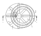
図1に原理的に示されたサテライト型伝動装置は、内歯11を有する中空円板として構成されたリング円板10を有している。さらにこのリング円板10は周方向溝12を有し、該周方向溝12内でクランプエレメントとしてのサテライト体が循環運動させられる。このリング円板10は入力エレメントとして用いられる。出力エレメントとしては半径方向溝14を有する星形板13が設けられている。作用するトルクはサテライト体15を介し伝達される。このサテライト体15は連結状態で歯17でリング円板10の歯11に形状接続で噛合う。各サテライト体15は一体成形された案内輪郭18を介し周方向溝12において案内されている。サテライト体15に一体成形されたピン19はサテライト体15が連結解除状態に反跳することを阻止する。何故ならばピン19は所定の角度に達した場合に同様に溝に衝突するからである。
The satellite transmission shown in principle in FIG. 1 has a
サテライト体15における本発明による半径方向溝20は、伝達ピン21がリング円板10に対し半径方向の補償運動を行なうことを許す。伝達ピン21の異なる直径とサテライト体15における溝20と星形板13における溝14との異なる幅とによって伝達ピン21が負荷のもとで溝14に接すると特に、伝達ピン21は半径方向溝20においては溝14におけるよりも軽く転動する。
The
本発明による別の構成によれば、伝達ピン21を所望の終端位置で、つまり溝20の端部に固持し、負荷円弧における半径方向の補償のための運動空間を与える図示されていないばね装置を使用することもできる。
According to another configuration according to the invention, a spring device (not shown) which holds the
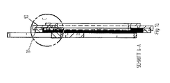
図2aから2cまでにはカム状の溝31を有する内側の定置の円板30が示されている。前記溝31内には外側の回転する円板33のための軸受を形成する球32が転動できる。孔34は、6つ設けられている案内の内、1つの案内しか図示されていない半径方向案内35を図1の伝達ピン21に相応する伝達ピン37を介して保持する。
FIGS. 2 a to 2 c show an inner
半径方向案内35は伝達ピン37で前記入力円板の図示されていないエレメントに係合する。半径方向案内35は伝達ピン37を中心として回転することができる。この場合、この回転はカム状の溝31にて案内されているピン38を介して制御される。選ばれた前記構成により、半径方向案内35は常に同じ個所にて、つまり負荷円弧にて回転としての修正運動を行なうので不等速性が減じられる。
The
別の図3aから図3dまでに示された別の実施例においては星形板は幾何学的に固定された半径方向溝を備えて構成されているのではなく、その代わりに円板40の上に案内エレメント41を有している。これらの案内エレメント41はクランプ42で結合されかつ軸43を中心として回転することができる。これらの軸43の相関位置及びクランプ42の方向は、案内エレメント41の間に形成された、サテライト体50の伝達ピン52が滑動する半径方向溝が、案内エレメント41が軸43を中心として伝動装置の回転方向へ回転するとただちに狭まるように選択されている。この回転はストッパ44により制限されている。負荷円弧に侵入する際に各サテライト体50は連結する。この場合、負荷方向は変換するので、自由回転方向でストッパ44の1つに接触する案内エレメント41は軸43を中心として回転し、その際に半径方向溝が狭められる。半径方向溝内には該当する伝達ピン52が位置しているので、同時にクランプされる伝達ピンの直径よりも溝幅が小さくなると伝達ピンの回転がロックされるので、伝達ピンのさらなる半径方向の運動は阻止される。これによりさらなる補償運動はサテライト体50の溝53内でしか行なわれないので、負荷円弧へ侵入する場合には自動的な補整運動のシフトが行なわれる。負荷円弧から出る場合には記述した過程は同様に反対の方向に経過する。
In another embodiment, shown in the other FIGS. 3a to 3d, the star plate is not constructed with geometrically fixed radial grooves, but instead of the disc 40. A guide element 41 is provided on the top. These guide elements 41 are connected by a
連接体を有する構成では連接体の回転は適当なメカニズムで負荷円弧にて阻止されて、相対運動はサテライト溝にシフトされる。 In the configuration having the connecting body, the rotation of the connecting body is blocked by the load arc by an appropriate mechanism, and the relative motion is shifted to the satellite groove.
不等速性を減じる別の可能性は、星形板の半径方向溝が回転運動及び組合わされた回転−並進運動を実施できるように個別に前記円板に固定されることで達成される。この運動は不動の円板の上に固定されたカム状の周方向溝内で回転する案内ピンによって制御される。これにより半径方向溝は記述した運動を常に定置の位置から偏心性に関連して、したがって常に負荷円弧入口にて開始して負荷円弧出口にて、もしくはその近くにて終了するように実施するので、カム溝の適宜の輪郭で不等速性の減少が達成される。 Another possibility to reduce the inconstancy is achieved by the fact that the radial grooves of the star plate are individually fixed to the disc so as to be able to carry out rotational movements and combined rotational-translational movements. This movement is controlled by a guide pin that rotates in a cam-like circumferential groove fixed on a stationary disk. This ensures that the radial groove always carries out the described movement in relation to the eccentricity from the stationary position and therefore always starts at the load arc inlet and ends at or near the load arc outlet. A reduction in inequality is achieved with an appropriate contour of the cam groove.
伝達における相対運動は、半径方向溝内で外側を伝達ピンが走行するほど、したがってこのパラメータに関して各偏心性に対するカムの影響が異なるほど大きい。したがって同じカムで考えられ得る伝達比のための良好な適合が達成される。 The relative movement in transmission increases as the transmission pin travels outside in the radial groove and thus the influence of the cam on each eccentricity with respect to this parameter differs. A good fit for the transmission ratio that can be considered with the same cam is thus achieved.
図4にはリング円板の歯11に適合させられた歯17の所定のプロフィルを有するサテライト体15が示されている。図面は無負荷円弧から負荷円弧への移行が示されている。その際、サテライト体15は矢印22に示された旋回運動を実施する。図示の周方向力Uは矢印方向に偏心的な伝達ピン21を介しサテライト体15に作用する。歯力Zはサテライト体の歯17と、リング円板の歯11との接触を介し、反対方向に作用するので、サテライト体15は矢印方向の回転を行なう。この回転に抗しては摩擦力Rが作用する。この摩擦力は回転軸に対し間隔(a)をおいて作用し、ひいてはトルクMr=Rxaを発生させる。確実なロックの条件は力対偶UとZからのトルクがあらゆる条件下で、すなわちサテライト体15の位置がもっとも不都合な場合でかつ潤滑がもっとも悪い場合に摩擦モーメントMrよりも大きいと達成される。この場合にはサテライト体は常に、サテライト体が一杯の歯噛合(歯11,17)状態にあってはじめて全周方向力を受止めかつ歯先に負荷がかかることはない。すべての力とトルクを考慮して、角速度が高い場合にサテライト体と伝達エレメントに作用する遠心力とコリオリ力とからの図示されていない動的な力を考慮しかつ伝達ピンにおける同様に図示されていない摩擦モーメントを考慮して、伝動装置は、すべてのロックされたすべてのモーメント(矢印22)の和が反対のトルクの和よりも常に大きいように構成される。
FIG. 4 shows a
図5にはそれぞれ1つの伝達ピン19によって半径方向セグメント62における負荷を導く周方向力を保持円板63に伝達する循環するサテライト体15を有するリング円板10が示されている。この場合、回転軸64は半径方向セグメント62の回転を許す。この半径方向セグメント62は、図示されていないが原理的には公知であるばね/緩衝エレメントにより0位置(半径方向の位置)に安定化させられている。
FIG. 5 shows a
択一的に伝達ピン19は、該伝達ピン19がリング円板10の対応するリング溝内に形状接続的に位置し、同様に半径方向セグメント62の半径方向溝内に形状接続で案内されるように構成されている。このような形式で半径方向セグメント62は常にリング円板10の中心点に対し方向付けられる。
Alternatively, the
10 リング円板、 11 内歯、 12 周方向溝、 13 星形板、 14 半径方向溝、 15 サテライト体、 17 歯、 18 案内輪郭、 19 ピン、 20 半径方向溝、 21 伝達ピン、 30 円板、 31 溝、 32 球、 33 円板、 34 孔、 35 半径方向案内、 37 伝達ピン、 38 ピン、 40 円板、 41 案内エレメント、 42 クランプ、 43 軸、 44 ストッパ、 50 サテライト体、 52 伝達ピン、 53 溝、 60 リング円板、 61 周方向溝、 62 半径方向溝、 63 保持円板、 64 回転軸 10 ring discs, 11 internal teeth, 12 circumferential grooves, 13 star plates, 14 radial grooves, 15 satellite bodies, 17 teeth, 18 guide contours, 19 pins, 20 radial grooves, 21 transmission pins, 30 discs , 31 groove, 32 sphere, 33 disk, 34 hole, 35 radial guide, 37 transmission pin, 38 pin, 40 disk, 41 guide element, 42 clamp, 43 shaft, 44 stopper, 50 satellite body, 52 transmission pin 53 grooves, 60 ring disks, 61 circumferential grooves, 62 radial grooves, 63 holding disks, 64 rotating shafts
Claims (20)
Applications Claiming Priority (2)
| Application Number | Priority Date | Filing Date | Title |
|---|---|---|---|
| DE10201738A DE10201738A1 (en) | 2002-01-18 | 2002-01-18 | satellite transmission |
| PCT/EP2003/000355 WO2003060348A1 (en) | 2002-01-18 | 2003-01-15 | Satellite gearing |
Publications (2)
| Publication Number | Publication Date |
|---|---|
| JP2005515371A true JP2005515371A (en) | 2005-05-26 |
| JP2005515371A5 JP2005515371A5 (en) | 2006-02-02 |
Family
ID=7712438
Family Applications (1)
| Application Number | Title | Priority Date | Filing Date |
|---|---|---|---|
| JP2003560406A Pending JP2005515371A (en) | 2002-01-18 | 2003-01-15 | Satellite type transmission |
Country Status (8)
| Country | Link |
|---|---|
| US (1) | US20050120816A1 (en) |
| EP (1) | EP1466110B1 (en) |
| JP (1) | JP2005515371A (en) |
| CN (1) | CN1596350A (en) |
| AT (1) | ATE310187T1 (en) |
| AU (1) | AU2003205609A1 (en) |
| DE (2) | DE10201738A1 (en) |
| WO (1) | WO2003060348A1 (en) |
Families Citing this family (6)
| Publication number | Priority date | Publication date | Assignee | Title |
|---|---|---|---|---|
| DE102004004849A1 (en) * | 2004-01-30 | 2005-08-18 | Fischer, Ina | Continuously variable, rotating change-speed gearbox |
| DE102004004850A1 (en) * | 2004-01-30 | 2005-08-18 | Fischer, Ina | Actuator with tap position in satellite gearboxes |
| CN103527735B (en) * | 2013-11-04 | 2017-02-08 | 苏州建莱机械工程技术有限公司 | Planet intermittent synchronizing mechanism |
| ITUB20156266A1 (en) * | 2015-12-03 | 2017-06-03 | Constantin Edyson Pavilcu | TRANSMISSION WITH VARIABLE SPEED REPORT |
| CN106931053A (en) * | 2017-04-18 | 2017-07-07 | 郭克亚 | A kind of wedge block type clutch |
| CN116773673B (en) * | 2023-08-23 | 2023-10-27 | 广州瑞港消防设备有限公司 | Detection device and detection method for tank body of non-pressure-storage fire extinguisher |
Family Cites Families (8)
| Publication number | Priority date | Publication date | Assignee | Title |
|---|---|---|---|---|
| GB821857A (en) * | 1955-06-22 | 1959-10-14 | Michael Wienand | Improvements in or relating to variable speed torque transmission arrangements |
| US3329031A (en) * | 1964-09-08 | 1967-07-04 | Leon H Maurer | Torque converter |
| US4091684A (en) * | 1974-11-15 | 1978-05-30 | Mathias Bauerle Gmbh | Variable speed control apparatus |
| US5048358A (en) * | 1990-06-04 | 1991-09-17 | Thurston, Inc. | Rotary phased radial thrust variable drive transmission |
| US5653142A (en) * | 1996-02-05 | 1997-08-05 | Kato; Humio | Intermittently rotary gearing |
| US6336887B1 (en) * | 1996-11-21 | 2002-01-08 | Aimbridge Pty Ltd. | Double orbital transmission |
| DE19734962A1 (en) * | 1997-08-13 | 1999-02-18 | Fischer Herwig | Overriding clutch with drive and driven element |
| DE19953643B4 (en) * | 1999-11-09 | 2005-02-03 | Innowacja Consulting | Stepless transmission |
-
2002
- 2002-01-18 DE DE10201738A patent/DE10201738A1/en not_active Withdrawn
-
2003
- 2003-01-15 CN CNA038016389A patent/CN1596350A/en active Pending
- 2003-01-15 US US10/501,615 patent/US20050120816A1/en not_active Abandoned
- 2003-01-15 AT AT03702446T patent/ATE310187T1/en not_active IP Right Cessation
- 2003-01-15 EP EP03702446A patent/EP1466110B1/en not_active Expired - Lifetime
- 2003-01-15 WO PCT/EP2003/000355 patent/WO2003060348A1/en active IP Right Grant
- 2003-01-15 DE DE50301670T patent/DE50301670D1/en not_active Expired - Fee Related
- 2003-01-15 AU AU2003205609A patent/AU2003205609A1/en not_active Abandoned
- 2003-01-15 JP JP2003560406A patent/JP2005515371A/en active Pending
Also Published As
| Publication number | Publication date |
|---|---|
| EP1466110A1 (en) | 2004-10-13 |
| ATE310187T1 (en) | 2005-12-15 |
| WO2003060348A1 (en) | 2003-07-24 |
| CN1596350A (en) | 2005-03-16 |
| DE50301670D1 (en) | 2005-12-22 |
| US20050120816A1 (en) | 2005-06-09 |
| DE10201738A1 (en) | 2003-07-31 |
| EP1466110B1 (en) | 2005-11-16 |
| AU2003205609A1 (en) | 2003-07-30 |
Similar Documents
| Publication | Publication Date | Title |
|---|---|---|
| US4487085A (en) | Infinitely variable gear ratio transmission | |
| WO2017201078A1 (en) | Systems and methods for axial force generation | |
| US4593574A (en) | Torque-dependent pressure mechanism for continuously adjustable ball-type planetary gear set | |
| CN110036222B (en) | Traction transmission and drive unit for a motor vehicle | |
| US20020151396A1 (en) | Positive engagement continuously variable transmission | |
| US7955203B2 (en) | Non-slip transmissions particularly useful as continuously-variable transmissions and transmission members thereof | |
| JP2005515371A (en) | Satellite type transmission | |
| US6327926B1 (en) | Directional clutch | |
| JP2520820B2 (en) | Differential gear | |
| JPH08506648A (en) | Backlash-free transmission | |
| US5514040A (en) | Variable-speed belt drive having toothed flyweights | |
| EP1214533B1 (en) | Continuous variable transmission | |
| JP4316493B2 (en) | Automatic transmission with at least two conical disc pairs | |
| GB2134208A (en) | Nutating gear transmission | |
| US4184388A (en) | Infinitely variable speed transmission | |
| KR20180087355A (en) | Continuously Variable Planetary Gear Transmission | |
| JP4868861B2 (en) | Planetary gear type continuously variable transmission | |
| EP0105370A4 (en) | Gear train having an internal gear mechanism. | |
| US3620102A (en) | Adjustable roller worm gear arrangements | |
| JP2006513379A (en) | Infinitely adjustable transmission | |
| US5057057A (en) | Continuously controllable drive | |
| JP2007113749A (en) | Continuously variable transmission | |
| JP2000320634A (en) | Toroidal continuous variable transmission device | |
| JP3696373B2 (en) | Continuously variable transmission | |
| JP2000291756A (en) | Toroidal type continuously variable transmission |
Legal Events
| Date | Code | Title | Description |
|---|---|---|---|
| A521 | Request for written amendment filed |
Free format text: JAPANESE INTERMEDIATE CODE: A523 Effective date: 20051209 |
|
| A621 | Written request for application examination |
Free format text: JAPANESE INTERMEDIATE CODE: A621 Effective date: 20051209 |
|
| A131 | Notification of reasons for refusal |
Free format text: JAPANESE INTERMEDIATE CODE: A131 Effective date: 20081024 |
|
| A601 | Written request for extension of time |
Free format text: JAPANESE INTERMEDIATE CODE: A601 Effective date: 20090126 |
|
| A602 | Written permission of extension of time |
Free format text: JAPANESE INTERMEDIATE CODE: A602 Effective date: 20090202 |
|
| A02 | Decision of refusal |
Free format text: JAPANESE INTERMEDIATE CODE: A02 Effective date: 20090423 |