JP2005512634A - Apparatus and method for delivering stents - Google Patents
Apparatus and method for delivering stents Download PDFInfo
- Publication number
- JP2005512634A JP2005512634A JP2003552172A JP2003552172A JP2005512634A JP 2005512634 A JP2005512634 A JP 2005512634A JP 2003552172 A JP2003552172 A JP 2003552172A JP 2003552172 A JP2003552172 A JP 2003552172A JP 2005512634 A JP2005512634 A JP 2005512634A
- Authority
- JP
- Japan
- Prior art keywords
- outer tube
- stent
- distal end
- sleeve
- inner tube
- Prior art date
- Legal status (The legal status is an assumption and is not a legal conclusion. Google has not performed a legal analysis and makes no representation as to the accuracy of the status listed.)
- Pending
Links
Images


Classifications
-
- A—HUMAN NECESSITIES
- A61—MEDICAL OR VETERINARY SCIENCE; HYGIENE
- A61F—FILTERS IMPLANTABLE INTO BLOOD VESSELS; PROSTHESES; DEVICES PROVIDING PATENCY TO, OR PREVENTING COLLAPSING OF, TUBULAR STRUCTURES OF THE BODY, e.g. STENTS; ORTHOPAEDIC, NURSING OR CONTRACEPTIVE DEVICES; FOMENTATION; TREATMENT OR PROTECTION OF EYES OR EARS; BANDAGES, DRESSINGS OR ABSORBENT PADS; FIRST-AID KITS
- A61F2/00—Filters implantable into blood vessels; Prostheses, i.e. artificial substitutes or replacements for parts of the body; Appliances for connecting them with the body; Devices providing patency to, or preventing collapsing of, tubular structures of the body, e.g. stents
- A61F2/95—Instruments specially adapted for placement or removal of stents or stent-grafts
- A61F2/962—Instruments specially adapted for placement or removal of stents or stent-grafts having an outer sleeve
- A61F2/966—Instruments specially adapted for placement or removal of stents or stent-grafts having an outer sleeve with relative longitudinal movement between outer sleeve and prosthesis, e.g. using a push rod
-
- A—HUMAN NECESSITIES
- A61—MEDICAL OR VETERINARY SCIENCE; HYGIENE
- A61F—FILTERS IMPLANTABLE INTO BLOOD VESSELS; PROSTHESES; DEVICES PROVIDING PATENCY TO, OR PREVENTING COLLAPSING OF, TUBULAR STRUCTURES OF THE BODY, e.g. STENTS; ORTHOPAEDIC, NURSING OR CONTRACEPTIVE DEVICES; FOMENTATION; TREATMENT OR PROTECTION OF EYES OR EARS; BANDAGES, DRESSINGS OR ABSORBENT PADS; FIRST-AID KITS
- A61F2/00—Filters implantable into blood vessels; Prostheses, i.e. artificial substitutes or replacements for parts of the body; Appliances for connecting them with the body; Devices providing patency to, or preventing collapsing of, tubular structures of the body, e.g. stents
- A61F2/95—Instruments specially adapted for placement or removal of stents or stent-grafts
- A61F2/962—Instruments specially adapted for placement or removal of stents or stent-grafts having an outer sleeve
- A61F2/966—Instruments specially adapted for placement or removal of stents or stent-grafts having an outer sleeve with relative longitudinal movement between outer sleeve and prosthesis, e.g. using a push rod
- A61F2002/9665—Instruments specially adapted for placement or removal of stents or stent-grafts having an outer sleeve with relative longitudinal movement between outer sleeve and prosthesis, e.g. using a push rod with additional retaining means
Landscapes
- Health & Medical Sciences (AREA)
- Engineering & Computer Science (AREA)
- Biomedical Technology (AREA)
- Cardiology (AREA)
- Oral & Maxillofacial Surgery (AREA)
- Transplantation (AREA)
- Heart & Thoracic Surgery (AREA)
- Vascular Medicine (AREA)
- Life Sciences & Earth Sciences (AREA)
- Animal Behavior & Ethology (AREA)
- General Health & Medical Sciences (AREA)
- Public Health (AREA)
- Veterinary Medicine (AREA)
- Media Introduction/Drainage Providing Device (AREA)
- Prostheses (AREA)
Abstract
自己拡張型ステントを搬送装置内に挿入した後、体腔内に同ステントを搬送するための方法及び装置に関する。装置は、外管203と、外管内の内管201と、内管上に摺動可能に取り付けられた捕捉要素206と、同捕捉要素は、外管よりも小さい基端部と外管よりも大きい先端部を有する折畳み可能なスリーブ207を備えることと、内管に固定された制止要素207と、同制止要素は、制止要素の基端側のスリーブ207内にステントが挿入されることを阻止し、捕捉要素206が内管に対して所定の位置の先端側に位置することを阻止すべく構成されていることとからなる。ステント205は、搬送装置200を体腔内に挿入して、搬送装置の先端部をステント配置部位に近接して配置し、ステント205に対して基端方向に外管を後退させて、内管上の制止要素207により、ステントが外管と共に後退されることを阻止して、ステントを径方向に収縮した状態から解放して配置する。 The present invention relates to a method and apparatus for delivering a self-expanding stent into a body cavity after insertion into the delivery device. The apparatus includes an outer tube 203, an inner tube 201 in the outer tube, a capture element 206 slidably mounted on the inner tube, and the capture element is smaller than the proximal end and the outer tube. Providing a foldable sleeve 207 with a large distal end, a restraining element 207 secured to the inner tube, and the restraining element prevents the stent from being inserted into the sleeve 207 on the proximal side of the restraining element. And the capture element 206 is configured to prevent the capture element 206 from being positioned at the distal end side of the predetermined position with respect to the inner tube. The stent 205 is inserted into the body cavity, the distal end portion of the delivery device is placed close to the stent placement site, the outer tube is retracted in the proximal direction with respect to the stent 205, and the The restraining element 207 prevents the stent from being retracted together with the outer tube, and releases the stent from the radially contracted state.
Description
本発明は、自己拡張型ステント、グラフト、ステントグラフト、被覆ステント等を体腔内に搬送することに関する。より詳細には、本発明は、自己拡張型ステント等を搬送装置に装着及び搬送装置から解放することに関する。 The present invention relates to delivering self-expanding stents, grafts, stent-grafts, coated stents and the like into body cavities. More particularly, the invention relates to mounting and releasing a self-expanding stent or the like from a delivery device.
外科的に体腔(管状をなす体内管)に埋め込まれる自己拡張型のステント、例えば編成されたステントは、体腔を修復したり、補強したりするものとして知られている。ステントは、基本的には、体腔を補う中空状の管である。体腔が壊れたり、閉塞したりする傾向にある狭窄の病状に対して、ステントは、体腔の壁を支持することにより、血管壁が壊れたり、閉塞したりするのを防止する。内部にプラークが形成されて狭くなった血管は、狭窄の一例である。体腔が脆弱化し、管内の内圧に耐えることができずに膨れたり、破裂したりする動脈瘤の病状に対しては、グラフト又はステントグラフトは、基本的には逆の役割、即ち、体腔の脆弱化した部分を補って、代替的な働きをする。ステントは、血管、胆管、結腸、気管、食道、尿道、尿管、鼻腔、管状器官等に挿入するものとして知られている。 Self-expanding stents, such as knitted stents, that are surgically implanted in body cavities (tubular body vessels) are known to repair and reinforce body cavities. A stent is basically a hollow tube that supplements a body cavity. For stenotic conditions where the body cavity tends to break or occlude, the stent prevents the vessel wall from being broken or occluded by supporting the wall of the body cavity. A blood vessel that is narrowed due to the formation of plaque inside is an example of stenosis. For aneurysm pathology where the body cavity becomes weak and cannot withstand the internal pressure in the tube and swells or ruptures, the graft or stent graft is essentially the opposite role, ie weakening of the body cavity Compensate for the parts that have been replaced, and work as an alternative. Stents are known for insertion into blood vessels, bile ducts, colon, trachea, esophagus, urethra, ureter, nasal cavity, tubular organs and the like.
ステントは、力により曲げられたときに曲がった形状を保持する、硬度に優れるものの変形可能な材料から製造される。このようなステントは、収縮された状態のバルーン上に取り付けられ、圧力を付与されていない、径方向において最小の大きさとなる形態で体腔に挿入することができる。ステントが本来の位置に配置されると、ステントを径方向に拡張するためにバルーンが拡張され、ステントはバルーンが収縮され、除去された後も、その径方向に拡張された形状を保持する。 Stents are manufactured from a hard but deformable material that retains a bent shape when bent by force. Such a stent is mounted on a balloon in a deflated state, and can be inserted into a body cavity in a form having a minimum size in the radial direction without applying pressure. When the stent is in place, the balloon is expanded to radially expand the stent, and the stent retains its radially expanded shape after the balloon is deflated and removed.
他のタイプのステントも、自己拡張型のステントと呼ばれる。自己拡張型のステントは、径方向に圧縮可能であるが、径方向に収縮する力がなくなると、本来の形状に拡張される。自己拡張型のステントのいくつかのタイプは、超弾性の材料又は形状記憶特性を有する材料で形成される。このようなステントは、化学組成や熱加工処理の過程により、形状記憶材料又は超弾性材料として使用することができ、生体適合性を有する合金であるニチノールで通常は形成される。ボストンサイエンティフィック社(Boston Scientific Corporation )により製造・販売されるウルトラフレックス(登録商標ULTRAFLEX)のステントは、編成されたニチノール製ステントの一例である。 Other types of stents are also referred to as self-expanding stents. A self-expanding stent is radially compressible, but expands to its original shape when there is no radial contraction force. Some types of self-expanding stents are formed of superelastic materials or materials with shape memory properties. Such stents can be used as shape memory materials or superelastic materials, depending on their chemical composition and thermal processing, and are usually formed from nitinol, a biocompatible alloy. The Ultraflex® ULTRAFLEX stent manufactured and sold by Boston Scientific Corporation is an example of a knitted Nitinol stent.
径方向に圧縮されたときに弾性変形しただけであるため、元の形状に戻る他のタイプの自己拡張型のステントは、ウォールステン(Wallsten)に付与された特許文献1に例示される。特許文献1の出願人は、自己拡張型で網目状をなす、外科的に拡張を行うステントを開示しており、このステントは、特に冠状動脈の拡張に使用されるが、他の体腔での使用ができるように変更可能である。同特許文献1は、概ね、本願において図1Aに示すステント10を開示している。同ステントは、中空状の管状部材からなり、管状部材の壁は、個々の可撓性を有する糸状要素12,14が連なって形成される。糸状要素12,14は、各々、ステントの中心の長手方向の軸の周囲に螺旋状に延びる。可撓性を有する糸要素12からなる第1の集合体は、同一方向に巻回され、ステントの円筒形状をなす表面の周囲において、互いに対して入れ替わるように配置される。糸状要素12からなる第1の集合体は、螺旋状をなす糸状要素14からなる第2の集合体と交差する。糸要素14からなる第2の集合体も、ステントの円筒形状をなす表面の周囲において、互いに対して入れ替わるように配置されるが、巻回の方向が逆となる。従って、図1Aに示すように、第1の集合体としての糸状要素12は、第2の集合体としての糸状要素14と、交点16において交差する。
Another type of self-expanding stent that returns to its original shape because it has only been elastically deformed when compressed in the radial direction is exemplified in US Pat. The applicant of Patent Document 1 discloses a self-expanding, net-like, surgically-expanding stent, which is used in particular for the expansion of coronary arteries, but in other body cavities. It can be changed so that it can be used. The patent document 1 generally discloses the
ステントは軸方向において伸張するにつれて、即ち、長手方向における端部18,20が互いに対して離れるように強いられると、図1Bに示すように、直径が縮小する。同様に、ステントの壁が径方向に収縮されて、ステントの直径が小さくなると、ステントは伸張する。換言すれば、径方向における収縮及び軸方向における伸張は、関連して起こる。圧力が付与されなくなると、ステントは休止時の直径及び長さに復帰しようとする。
As the stent expands in the axial direction, i.e., when the
生体吸収性を備えたステントも、従来技術において知られている。生体吸収性のステントは、体内の流体に接触するうちに、時間の経過とともに分解され、体内における周囲の細胞に吸収される材料から製造される。 ポリ−L,D−乳酸、ポリ−L−乳酸、ポリ−D−乳酸、ポリグリコール酸、ポリ乳酸、ポリカプロラクトン、ポリジオキサノン、ポリ(乳酸−エチレンオキシド)共重合体やこれらの組み合わせ等のポリマーを含むステント製造に適した様々な生体吸収性の材料が、従来技術において知られている。 Stents with bioabsorbability are also known in the prior art. Bioabsorbable stents are manufactured from materials that degrade over time while in contact with fluids in the body and are absorbed by surrounding cells in the body. Including polymers such as poly-L, D-lactic acid, poly-L-lactic acid, poly-D-lactic acid, polyglycolic acid, polylactic acid, polycaprolactone, polydioxanone, poly (lactic acid-ethylene oxide) copolymer and combinations thereof Various bioabsorbable materials suitable for stent manufacture are known in the prior art.
非特許文献1、特許文献2、特許文献3、特許文献4、特許文献5、特許文献6、特許文献7、特許文献8、及び特許文献9は、生体吸収性を備えたステントの製造に適した化合物を開示しており、これらの文献に開示された化合物は、本願においても開示されたものとする。 Non-Patent Literature 1, Patent Literature 2, Patent Literature 3, Patent Literature 4, Patent Literature 5, Patent Literature 6, Patent Literature 7, Patent Literature 8, and Patent Literature 9 are suitable for manufacturing a bioabsorbable stent. The compounds disclosed in these documents are also disclosed in the present application.
ほとんどのステントは、体腔内に挿入できるように、径方向において収縮される、即ち直径が小さくなる必要がある。更に、ステントが本来の位置にある時、ステントは解放されて径方向に拡張する。 Most stents need to be radially contracted, i.e., reduced in diameter, so that they can be inserted into a body cavity. Furthermore, when the stent is in place, it is released and expands radially.
径方向において収縮されたステントを体腔に搬送し、次に体腔内で自己拡張できるようにステントを解放するための異なる搬送装置は、周知である。特許文献10に開示され、図2において示された装置により例示された周知の一実施例において、搬送装置は、同心円の外管1に囲まれた内管5を有する。外管は内管よりも短いため、内管は、両端部において外管から延びる。ハンドル6は、通常、内管の基端部において構成される。他のハンドル2は、外管の基端部において構成される。内部コアは、これら2つのハンドルを相対的に操作することにより、外管内において摺動可能である。ステント11は、搬送装置の先端部付近において、内管と外管との間に固定された搬送装置内に装着される。
Different delivery devices are known for delivering a radially contracted stent into a body cavity and then releasing the stent so that it can self-expand within the body cavity. In a well-known embodiment disclosed in US Pat. No. 6,057,086 and illustrated by the apparatus shown in FIG. 2, the transport device has an inner tube 5 surrounded by a concentric outer tube 1. Since the outer tube is shorter than the inner tube, the inner tube extends from the outer tube at both ends. The handle 6 is usually configured at the proximal end of the inner tube. The other handle 2 is configured at the proximal end of the outer tube. The inner core can slide within the outer tube by relatively operating these two handles. The
内部コアは、中空状であり、ガイドワイヤ8を収容するように構成され、ガイドワイヤ8は、従来技術において周知であり、体腔4内のステント搬送部位まで装置を誘導するために使用される。 The inner core is hollow and is configured to receive a guide wire 8, which is well known in the prior art and is used to guide the device to the stent delivery site within the body cavity 4.
ステントを搬送する際に、医師は通常、所望のステント配置部位から離れた箇所において体腔4を切開し、ステント搬送装置の先端部がステント配置部位に達するまで体腔内にステント搬送装置を誘導する。次に、外管1は、基端方向に後退し、一方、内管5は静止している。従って、外管1は、ステント11上を摺動し、ステントを径方向に収縮した状態から解放することにより、ステントが径方向に拡張して体腔4の壁に接触する。ステントの径方向への拡張力により生じた、体腔の壁とステント本体との間の摩擦力により、ステント11は所定の位置に保持される。ステントが完全に配置され、搬送装置が後退して、処置が完了する。
本発明の目的は、ステントを体腔内に搬送するための改良された方法及び装置を提供することにある。 It is an object of the present invention to provide an improved method and apparatus for delivering a stent into a body cavity.
本発明は、自己拡張型ステントを体腔内に搬送するための方法及び装置に関する。装置は、基端部及び先端部を有する外管と、外管はその中に径方向に収縮した状態の自己拡張型ステントを保持するように寸法が設定されていることと、外管内にあり、基端部及び先端部を有する内管と、内管上に対して摺動可能に取り付けられた捕捉要素と、同捕捉要素は、ステントを径方向に収縮させるための補助をする折畳み可能なスリーブを備え、これら2つの管の間の搬送装置内にステントを挿入することと、内管の先端部付近において同管に対して固定された制止要素と、制止要素は、捕捉要素を外管内に引込み、スリーブ内に挿入されたステントが所定の位置を越えて保持装置内に挿入されないように構成されていることとからなる。スリーブは、基端部及び先端部を有し、基端部は外管よりも小さく、先端部は外管よりも大きい。捕捉要素は内管上にあり、折畳まれていない状態において、スリーブの先端部は外管の先端部を越えて延び、内管が外管に対して基端方向に引寄せられると、スリーブは外管内に引込まれて、外管内で折畳まれる。従って、スリーブの先端部内に挿入された端部を有するステントは、内管を外管に対して基端方向に内管を引寄せることにより、外管内に引込まれて、ステントを外管内で径方向に収縮された状態において保持する。ステントは、内管に対して基端側にある外管を軸方向に移動させることにより、解放される。外管が内管に対して基端方向に移動すると、捕捉要素は、外管に係合し、且つ外管と共に引寄せられることにより、ステントの基端部の先端をスリーブより自由にして、ステントの解放を円滑に行うことができる。 The present invention relates to a method and apparatus for delivering a self-expanding stent into a body cavity. The device has an outer tube having a proximal end and a distal end, and the outer tube is dimensioned to hold a self-expanding stent in a radially contracted state therein, and is within the outer tube. An inner tube having a proximal end and a distal end, a capture element slidably mounted on the inner tube, and the capture element is foldable to assist in radially contracting the stent Including a sleeve, inserting a stent into the delivery device between the two tubes, a restraining element secured to the tube near the distal end of the inner tube, and a restraining element that attaches the capture element to the outer tube. And the stent inserted into the sleeve is configured not to be inserted into the holding device beyond a predetermined position. The sleeve has a proximal end portion and a distal end portion, the proximal end portion is smaller than the outer tube, and the distal end portion is larger than the outer tube. When the capture element is on the inner tube and is not folded, the distal end of the sleeve extends beyond the distal end of the outer tube, and when the inner tube is pulled proximally with respect to the outer tube, the sleeve Is drawn into the outer tube and folded in the outer tube. Therefore, a stent having an end portion inserted into the distal end portion of the sleeve is drawn into the outer tube by pulling the inner tube in the proximal direction with respect to the outer tube, and the stent is diametrated in the outer tube. Hold in a contracted state. The stent is released by axially moving the outer tube proximal to the inner tube. As the outer tube moves proximally relative to the inner tube, the capture element engages the outer tube and is pulled together with the outer tube, thereby freeing the proximal end of the stent from the sleeve, The stent can be released smoothly.
本発明の方法は、内管を配置する工程を有する、上記のステント搬送装置内にステントを装着する工程と、それにより捕捉要素の先端部は外管の先端部を越えて延びることと、ステントの端部をスリーブ内に挿入する工程と、スリーブとステントを外管内に引込むために、内管を外管に対して基端方向に引寄せる工程と、それによりスリーブとステントを外管内において径方向に収縮された状態で保持されることとからなる。 The method of the present invention includes the step of placing a stent within the stent delivery device described above, comprising the step of placing an inner tube, whereby the distal end of the capture element extends beyond the distal end of the outer tube; Inserting the end of the sleeve into the sleeve, pulling the inner tube proximally relative to the outer tube to retract the sleeve and stent into the outer tube, and thereby radially locating the sleeve and stent within the outer tube And held in a contracted state.
生体吸収性を備えた自己拡張型ステントは、多くの点において金属製の自己拡張型ステントに優る利点を有するが、潜在的な問題も有している。例えば、生体吸収性の自己拡張型ステントは、かなりの期間に渡って径方向に収縮された状態で保持されると、その状態で固定されがちであり、径方向の圧力が解放された時に、本来の直径にまで十分に拡張しない。たとえステントが本来の直径にまで拡張できたとしても、長期間に渡って径方向に収縮された状態で保持される前に比べて、径方向への拡張力が弱くなることがある。 Self-expanding stents with bioabsorbability have advantages over metal self-expanding stents in many respects, but also have potential problems. For example, a bioabsorbable self-expanding stent tends to become fixed when held in a radially contracted state for a significant period of time, when the radial pressure is released, Does not fully expand to the original diameter. Even if the stent can be expanded to its original diameter, the expansion force in the radial direction may be weaker than before the stent is held in a radially contracted state for a long period of time.
自己拡張型ステントは、通常、製造時にはステント搬送装置内に収容されている。従って、医師はすでに搬送装置内に収容されたステントを手にするため、医師がステントをステント搬送装置内に挿入するための機構を構成する必要はない。しかしながら、ステント及びステント搬送装置が製造され、医療処置において実際に使用されるまでに、相当な時間が経過し得る。この期間が、1年又は1年を越えることは珍しいことではない。上記の理由から、この点が、生体吸収性の自己拡張型ステントに関して問題となり得る。 Self-expanding stents are typically housed in stent delivery devices when manufactured. Accordingly, since the doctor has the stent already accommodated in the delivery device, it is not necessary for the physician to configure a mechanism for inserting the stent into the stent delivery device. However, considerable time can elapse before the stent and stent delivery device are manufactured and actually used in medical procedures. It is not uncommon for this period to be one year or more than one year. For the above reasons, this can be a problem with bioabsorbable self-expanding stents.
内管201と外管203との間の空間の断面積は、通常は極めて小さく、ステントの壁の厚さよりもわずかに大きいだけである。更に、冠動脈ステントなどの特定の実施例によっては、ステント及び搬送装置は極めて小さい。従って、医師が、手動でステントをステント搬送装置内に適切に挿入することは、不可能ではないにしても、極めて困難である。そのため、医療処置を行う直前に、医師が容易にステントを搬送装置内に挿入できるような、方法及び機構を提供することが望ましい。それにより、ステントが完全に拡張した状態で搬送装置の外部に配備されて、ステント及びその搬送装置が包装され得る。本発明は、そのようなシステムを提供することを目的とする。
The cross-sectional area of the space between the
本発明は、まず図3乃至6において例示した第1の実施例に関して説明される。
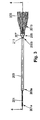
図3及び4は、それぞれ、本発明によるステント及びステント搬送装置の主要な要素の平面図及び断面図である。ハンドル、任意のガイドワイヤ及び装置の先端など、本発明に特に関連しない要素は、説明の明瞭化のために示していない。搬送装置200は、基端部200a及び先端部200bを有する。基端部は、医療処置の間、医師に把持される側である。先端部は、医療処置の間、体内腔に挿入される側である。装置200は、基端部201a及び先端部201bを備えた内管201、及び基端部203a及び先端部203bを備えた外管203を有する。ステント205は、搬送装置200内に挿入されて、外管203と内管201との間に径方向に収縮された状態に保持される。
The present invention will first be described with respect to the first embodiment illustrated in FIGS.
3 and 4 are a plan view and a cross-sectional view, respectively, of the main elements of the stent and stent delivery device according to the present invention. Elements not particularly relevant to the present invention, such as the handle, optional guidewire and device tip, are not shown for clarity. The transport apparatus 200 has a
図5において詳細が示される捕捉要素206は、ステントを搬送装置内に容易に挿入し、挿入中にステントの糸が解れたり、撓んだりしないように、ステントの基端側の先端を保護すべく構成される。捕捉要素206は、内管201を囲む帯状体状又はリング状であってもよいキャリッジ211を有し、内管201と外管203との間の隙間内に取り付けられ、内管201上を長手方向に摺動可能である。円錐形又は漏斗状のスリーブ207は、キャリッジ211の先端部において装着される。スリーブ207の基端部207aは、接着剤等により、キャリッジ211の先端部に固定して装着される。スリーブ207は、硬質ではなく、折畳み可能であり、捕捉要素206が外管203内に引込まれると、スリーブ207は収縮して折畳まれて、外管203内に収容される。スリーブ207は、ポリエチレンテレフタレート(PET)、ナイロン、ポリテトラフルオロエチレン(PTFE)又は他の好適な材料、若しくはそれらの組み合わせなどの生体適合性を有する薄いプラスチックから形成されてもよい。スリーブ207の内表面及び外表面は、ステントをスリーブ内に把持し、搬送装置の外管内にスリーブを後退させるために、異なる特性を有してもよい。従って、スリーブの内表面は、高い摩擦係数又は不均一な表面を有する材料或いはコーティング材からなってもよく、一方、スリーブの外部分は、低い摩擦係数を有する材料、或いはシリコン化処理又はハイドロゲルコーティングなどの加工により得られる滑らかなコーティング材からなってもよい。
The
他の実施例において、スリーブの内表面は、装置を生理食塩水で洗浄することにより活性化されるハイドロゲルコーティング材でコーティングされてもよく、ステントが搬送装置に完全に装着されて、ステントが解放され始める時に、スリーブからステントを円滑に解放できる。 In other embodiments, the inner surface of the sleeve may be coated with a hydrogel coating material that is activated by rinsing the device with saline, and the stent is fully attached to the delivery device so that the stent is As the release begins, the stent can be smoothly released from the sleeve.
スリーブ207の先端部207bは開口しており、実際に外管203の先端における開口部よりも大きい開口部を有する。スリーブ207の先端部207bにおける開口部は、径方向に収縮していないステントの直径と同じ、又はそれよりも大きくてもよいが、そうである必要はない。好適な実施例において、開口部は、収縮していないステントの直径よりも小さい。開口部は、手動又は他の余り面倒ではない器具で、ステントを径方向に収縮させることにより、医師がステントの一端をスリーブ207内に挿入できる程度の大きさである。ステントの一端部がスリーブ207内にある時は、ステントはスリーブ207内に押され続け(例えば、搬送装置の基端部方向へ)、それにより、スリーブ207の内壁はステントの同端部を径方向に収縮させて、外管203の内径よりも小さいスリーブ207の基端部207aの直径にまで収縮させる。この時点で、更にステントを基端方向に押し、及び/又は内管201を基端方向に引寄せることにより、ステントは、外管内に入り、外管203と内管201との間において、径方向に収縮した状態で搬送装置内に保持される。
The
異なる制止リング209は、キャリッジ211の先端側にある内管201に固定して装着される。これに代えて、制止リング209は、内管201と一体的に形成されてもよい。制止リング209は、2つの主な機能を有する。第1に、制止リング209は、ステントの端部が制止リング209の基端側(及び捕捉要素206の基端側)の搬送装置200内に挿入されることを阻止する。ステントが、内管201と捕捉要素206のキャリッジ211との間の隙間に入り込むことがある。制止リング209は、この現象を防止する。更に、制止リング209は、捕捉要素が内管の端部から落ちることを防止する。特に、制止リング209は、捕捉要素206のキャリッジ211が制止リング209の先端側に移動することを防止する。即ち、ステント205が搬送装置200内に挿入される間に、内管201は、外管203に対して基端方向に引寄せられる。内管201が基端方向に引寄せられると、制止リング209は、捕捉要素206のキャリッジ211に接触し、キャリッジ211を基端方向に引寄せる。或いは、内管201が、基端側に向かって外管203内に引込まれると、捕捉要素206は、内管201の先端部から落ちることがある。そのため、制止リング209は、捕捉要素206が内管に対して所定箇所の先端側に位置することを阻止する。
Different stop rings 209 are fixedly attached to the
図6に関して、内管201及び捕捉要素206が、外管に対して基端方向に引寄せられた時に、折畳み可能なスリーブ207は収縮して折畳まれ、外管の先端203bに接して、ステント205が保持されたように、内管201と外管203との間において折畳まれた状態で保持される。図6は、ステント205を有する搬送装置200の先端部及び捕捉要素206が、搬送装置200内に挿入されていることを示す。
With respect to FIG. 6, when the
これで、ステント及びステント搬送装置は、ステントが体腔内に配置されて、医療処置を行える状態となる。図7は、ステントの配置後のステント及びステント搬送装置の状態を示す。内管201が静止中に外管203が後退すると、捕捉要素206は、スリーブ207が外管203に摩擦係合するために、外管と共に後退し得る。従って、捕捉要素が内管に固定されると、スリーブ207は外管203の先端部203bから突出しないため、ステントが解放されることを妨害しない。外管が基端方向に後退してステントを解放すると、制止リング209は、内管に対してステントが基端方向へ移動することを防止して、外管の先端部が基端方向に後退して制止リングに達すると、ステントが完全に解放される。
Thus, the stent and the stent delivery device are in a state where the stent is disposed in the body cavity and medical treatment can be performed. FIG. 7 shows the state of the stent and stent delivery device after placement of the stent. When the
図8及び9は、捕捉要素であるキャリッジ211の他の実施例を示し、これらの実施例は、外管が基端方向に後退してステントを解放すると、捕捉要素206が確実に外管と共に後退するように構成される。例えば、図8に示す実施例において、キャリッジ211は先端に向かって角度をつけたバーブ801を有し、同バーブは外管203の内表面に係合し、外管に対して捕捉要素206の先端方向への移動を抑止するが、基端方向への移動は可能にする。
FIGS. 8 and 9 show other embodiments of the
図9に示す他の実施例において、バーブに代えて、1つ以上の板バネ901が、キャリッジ211の外表面上に配置され、先端に向かって斜めに延びて、外管203に対してキャリッジ211の先端方向への移動を抑止するが、外管に対してキャリッジの基端方向への移動は可能にする。
In another embodiment shown in FIG. 9, instead of barbs, one or
スリーブ207は、いずれの好適なポリマー、エラストマー、又は金属から形成されてもよい。スリーブ207は、内管と外管との間の隙間に流体が流れるように、多孔質であっても、せん孔又は溝を有してもよい。図に示す実施例において、内管201は、捕捉要素を越えて延びるため、ステントは、内管と外管との間に保持される。しかしながら、これは特に必要なことではない。制止リング209は、内管201の先端に装着されるため、ステントは、挿入されると外管内に保持されるので、内管はステントに近接しない。内管201は、硬質であっても又は中空状であってもよい。中空状である場合、ガイドワイヤは、搬送装置をステント配置部位に誘導するために使用されてもよいし、使用されなくてもよい。
The
捕捉要素の構成要素は、体温又は体液の存在において変わるような材料特性を有してもよい。例えば、捕捉要素206のキャリッジ211は、体温又は体液により拡張する材料から形成されてもよく、それにより、外管203の内表面とキャリッジ211との間に十分な強度を有する摩擦係合が生じ、外管が基端方向に後退すると、キャリッジ211は外管と共に移動する。更に、図はキャリッジ211及び制止リング209を硬質の環として示しているが、そうである必要はない。どちらの要素も、環状及び硬質である必要はない。スリーブ207についても同様である。キャリッジ211に対して、長手方向の溝又は穴を機械加工することにより、例えば、使用前にカテーテルを洗浄したり、処置中に造影剤を注入するために、内管と外管との間の隙間に流体が流れるようにしてもよい。
The components of the capture element may have material properties that vary in body temperature or in the presence of body fluids. For example, the
本発明は、上記したように、標準的な自己拡張型ステントに関するが、他のタイプのステントにも適用でき、実際に、同様の方法で搬送されるいずれの管状の自己拡張型の人工的補助器官であってもよい。例えば、本発明は、ステントグラフト及び被覆ステントにも同様に適用でき、両者とも当業者にとっては周知のステントを元にした医療用の人工器官である。実際に、この人工器官が自己拡張型である必要もない。本発明は、小径の開口部に挿入すべき、いずれの人工器官に関しても有効である。 Although the present invention relates to a standard self-expanding stent, as described above, it can be applied to other types of stents, and indeed any tubular self-expanding artificial aid delivered in a similar manner. It may be an organ. For example, the present invention is equally applicable to stent grafts and coated stents, both of which are medical prostheses based on stents well known to those skilled in the art. In fact, the prosthesis need not be self-expanding. The present invention is effective for any prosthesis to be inserted into a small diameter opening.
本発明のいくつかの特定の実施例について説明してきたが、当業者には、容易に様々な変更や修正や改良を加えることができるであろう。本願における開示により自明であるこのような変更、修正、改良は、本願に明示されていなくても、本願の記載に包含されるものであり、本発明の精神及び範囲から逸脱するものではない。従って、前述の説明は、本発明の例示を行うものであり、限定を行うものではない。本発明は、請求項に定義される事項と、これに均等の事項によってのみ、限定される。 While several specific embodiments of the present invention have been described, various changes, modifications and improvements will readily occur to those skilled in the art. Such alterations, modifications, and improvements that are obvious from the disclosure in the present application are included in the description of the present application, even if not explicitly stated in the present application, and do not depart from the spirit and scope of the present invention. Accordingly, the foregoing description is intended to be illustrative of the invention and not limiting. The present invention is limited only by the matters defined in the claims and the matters equivalent thereto.
Claims (21)
外管内において基端部及び先端部を有する内管と、
内管に対して摺動可能に係合した折畳み可能なスリーブを有する捕捉要素と、同スリーブは基端部及び先端部を有し、基端部は外管よりも小さく、先端部は外管よりも大きいことと、捕捉要素が内管上を移動することにより、スリーブの先端部は、非折畳み状態にある外管の先端部を越えて延び、内管が外管に対して基端方向に後退すると、スリーブは外管内に後退して、同外管内で折畳まれることと、スリーブの先端部内に挿入された端部を有するステントは外管内に後退することと、それによりステントは径方向に収縮された状態で外管内に保持されることと、
内管の先端部付近で同内管に対して固定された制止要素と、制止要素はスリーブ内に挿入されたステントが制止要素の基端側に位置すること阻止し、捕捉要素が内管に対して所定の位置の先端側に位置することを阻止するように構成されていることとからなる体腔内に自己拡張型ステントを搬送するための装置。 An outer tube having a proximal end and a distal end and dimensioned to hold a self-expanding stent in a radially contracted state therein;
An inner tube having a proximal end and a distal end in the outer tube;
A capture element having a foldable sleeve slidably engaged with the inner tube, the sleeve having a proximal end and a distal end, the proximal end being smaller than the outer tube, the distal end being the outer tube And the capture element moves over the inner tube, so that the distal end of the sleeve extends beyond the distal end of the unfolded outer tube, and the inner tube is proximal to the outer tube. The sleeve is retracted into the outer tube and folded within the outer tube, and the stent with the end inserted into the distal end of the sleeve is retracted into the outer tube, thereby causing the stent to Being held in the outer tube in a radially contracted state;
A restraining element fixed to the inner tube near the distal end of the inner tube, and the restraining element prevents the stent inserted in the sleeve from being positioned on the proximal side of the restraining element, and the capture element is attached to the inner tube. An apparatus for delivering a self-expanding stent into a body cavity comprising: being configured to prevent it from being positioned at a distal end of a predetermined position.
(1)捕捉要素の先端部が外管の先端部を越えて延びるように、内管を配置する工程と、
(2)ステントの一端をスリーブの先端部内に挿入する工程と、
(3)内管を外管に対して基端方向に後退させて、スリーブとステントを外管内に引込むことにより、スリーブとステントを径方向に収縮した状態で外管内に保持する工程とからなる方法。 A method of mounting a stent within a stent delivery device, the delivery device having an outer tube dimensioned to hold a radially expanded self-expanding stent therein, and an outer tube Has a proximal end and a distal end, an inner tube in the outer tube has a proximal end and a distal end, a capture element slidably attached to the inner tube, and the capture element is By providing a foldable sleeve having a proximal end and a distal end, the proximal end being smaller than the outer tube, the distal end being larger than the outer tube, and the capture element moving over the inner tube The distal end of the sleeve extends beyond the distal end of the outer tube in the unfolded state, and when the inner tube is retracted in the proximal direction with respect to the outer tube, the sleeve is retracted and folded into the outer tube. And the restraining element fixed to the inner pipe near the tip of the inner pipe is The stent inserted in the rib is configured to prevent the proximal end of the restraining element from being located, and to prevent the capture element from being located at the distal end of the predetermined position with respect to the inner tube; And the method further comprises:
(1) arranging the inner tube such that the distal end of the capture element extends beyond the distal end of the outer tube;
(2) inserting one end of the stent into the distal end of the sleeve;
(3) The inner tube is retracted in the proximal direction with respect to the outer tube, and the sleeve and the stent are drawn into the outer tube to hold the sleeve and the stent in the outer tube in a radially contracted state. Method.
(5)工程(4)の後で、内管とステントに対して基端方向に外管を後退させて、ステントを径方向に収縮した状態から解放する工程とを有する、請求項15に記載のステント搬送装置内に装着されたステントを体腔内に配置する方法。 (4) After step (3), inserting the delivery device into the body cavity and placing the distal end portion of the outer tube close to the stent placement site;
(5) After the step (4), the method includes a step of retracting the outer tube in the proximal direction with respect to the inner tube and the stent to release the stent from the radially contracted state. A method of placing a stent mounted in a stent delivery device of the above in a body cavity.
Applications Claiming Priority (2)
| Application Number | Priority Date | Filing Date | Title |
|---|---|---|---|
| US10/025,669 US6902575B2 (en) | 2001-12-18 | 2001-12-18 | Stent delivery apparatus and method |
| PCT/US2002/040673 WO2003051235A1 (en) | 2001-12-18 | 2002-12-18 | Stent delivery apparatus and method |
Publications (2)
| Publication Number | Publication Date |
|---|---|
| JP2005512634A true JP2005512634A (en) | 2005-05-12 |
| JP2005512634A5 JP2005512634A5 (en) | 2006-01-12 |
Family
ID=21827402
Family Applications (1)
| Application Number | Title | Priority Date | Filing Date |
|---|---|---|---|
| JP2003552172A Pending JP2005512634A (en) | 2001-12-18 | 2002-12-18 | Apparatus and method for delivering stents |
Country Status (6)
| Country | Link |
|---|---|
| US (1) | US6902575B2 (en) |
| EP (1) | EP1463460A1 (en) |
| JP (1) | JP2005512634A (en) |
| AU (1) | AU2002366382B2 (en) |
| CA (1) | CA2470433A1 (en) |
| WO (1) | WO2003051235A1 (en) |
Cited By (5)
| Publication number | Priority date | Publication date | Assignee | Title |
|---|---|---|---|---|
| JP2009537277A (en) * | 2006-05-19 | 2009-10-29 | ボストン サイエンティフィック リミテッド | Apparatus and method for loading and delivering a stent |
| JP2011510706A (en) * | 2008-01-24 | 2011-04-07 | ボストン サイエンティフィック サイムド,インコーポレイテッド | Stent loading and delivery apparatus and method with improved handle for controlling relative movement of catheter components |
| JP2012500075A (en) * | 2008-08-21 | 2012-01-05 | アンジオメト・ゲーエムベーハー・ウント・コンパニー・メディツィンテクニク・カーゲー | Method of loading a stent into a sheath |
| JP2014507198A (en) * | 2010-12-30 | 2014-03-27 | ボストン サイエンティフィック サイムド,インコーポレイテッド | On-board basket for stent delivery system |
| JP2014176652A (en) * | 2013-03-13 | 2014-09-25 | Depuy Synthes Products Llc | Capture tube mechanism for delivering and releasing stent |
Families Citing this family (51)
| Publication number | Priority date | Publication date | Assignee | Title |
|---|---|---|---|---|
| US8088060B2 (en) | 2000-03-15 | 2012-01-03 | Orbusneich Medical, Inc. | Progenitor endothelial cell capturing with a drug eluting implantable medical device |
| US9522217B2 (en) | 2000-03-15 | 2016-12-20 | Orbusneich Medical, Inc. | Medical device with coating for capturing genetically-altered cells and methods for using same |
| EP1521612B1 (en) * | 2002-06-28 | 2007-08-08 | Cook Critical Care | Introducer sheath |
| US8500792B2 (en) | 2003-09-03 | 2013-08-06 | Bolton Medical, Inc. | Dual capture device for stent graft delivery system and method for capturing a stent graft |
| US9198786B2 (en) | 2003-09-03 | 2015-12-01 | Bolton Medical, Inc. | Lumen repair device with capture structure |
| US20070198078A1 (en) | 2003-09-03 | 2007-08-23 | Bolton Medical, Inc. | Delivery system and method for self-centering a Proximal end of a stent graft |
| US8292943B2 (en) | 2003-09-03 | 2012-10-23 | Bolton Medical, Inc. | Stent graft with longitudinal support member |
| US20080264102A1 (en) | 2004-02-23 | 2008-10-30 | Bolton Medical, Inc. | Sheath Capture Device for Stent Graft Delivery System and Method for Operating Same |
| US11259945B2 (en) | 2003-09-03 | 2022-03-01 | Bolton Medical, Inc. | Dual capture device for stent graft delivery system and method for capturing a stent graft |
| US7763063B2 (en) | 2003-09-03 | 2010-07-27 | Bolton Medical, Inc. | Self-aligning stent graft delivery system, kit, and method |
| US11596537B2 (en) | 2003-09-03 | 2023-03-07 | Bolton Medical, Inc. | Delivery system and method for self-centering a proximal end of a stent graft |
| US9254213B2 (en) * | 2004-01-09 | 2016-02-09 | Rubicon Medical, Inc. | Stent delivery device |
| AU2005284739B2 (en) | 2004-09-14 | 2011-02-24 | Edwards Lifesciences Ag | Device and method for treatment of heart valve regurgitation |
| US7918880B2 (en) * | 2005-02-16 | 2011-04-05 | Boston Scientific Scimed, Inc. | Self-expanding stent and delivery system |
| DE102005021470A1 (en) * | 2005-05-10 | 2006-11-16 | Tracoe Medical Gmbh | Introducer for percutaneous tracheostomy |
| AU2005332044B2 (en) * | 2005-05-25 | 2012-01-19 | Covidien Lp | System and method for delivering and deploying and occluding device within a vessel |
| WO2007022496A2 (en) * | 2005-08-19 | 2007-02-22 | Icon Medical Corp. | Medical device deployment instrument |
| AU2007289078A1 (en) | 2006-08-30 | 2008-03-06 | David William Smith | Method of imparting a mono-axial or multiaxial stiffness to extruded materials and products resulting therefrom |
| US20080097517A1 (en) * | 2006-10-23 | 2008-04-24 | Webtec Converting, Llc. | External Nasal Dilator and Methods of Manufacture |
| EP2106250B1 (en) * | 2007-01-25 | 2020-04-01 | Boston Scientific Limited | Endoscope with preloaded or preloadable stent |
| CA2720466A1 (en) * | 2008-05-09 | 2009-11-12 | Juergen Dorn | Method of loading a stent into a sheath |
| US20100042202A1 (en) * | 2008-08-13 | 2010-02-18 | Kamal Ramzipoor | Composite stent having multi-axial flexibility |
| WO2010005524A2 (en) | 2008-06-30 | 2010-01-14 | Bolton Medical, Inc. | Abdominal aortic aneurysms: systems and methods of use |
| US8359721B2 (en) * | 2008-09-04 | 2013-01-29 | Cook Medical Technologies Llc | Sliding split-sleeve implant compressor |
| ES2812228T3 (en) | 2009-03-13 | 2021-03-16 | Bolton Medical Inc | System for deploying an endoluminal prosthesis at a surgical site |
| US8585019B2 (en) * | 2009-08-20 | 2013-11-19 | Cook Medical Technologies Llc | Loading apparatus and system for expandable intraluminal medical devices |
| US8900286B2 (en) * | 2010-03-01 | 2014-12-02 | Abbott Cardiovascular Systems, Inc. | Medical device shield and methods for delivering a medical device |
| US9320597B2 (en) * | 2010-03-30 | 2016-04-26 | Medtronic, Inc. | Transcatheter prosthetic heart valve delivery system with recapturing feature and method |
| US8979824B2 (en) | 2010-06-21 | 2015-03-17 | Boston Scientific Scimed, Inc. | Stent delivery system having retention structure |
| US8808348B2 (en) * | 2010-06-23 | 2014-08-19 | Boston Scientific Scimed, Inc. | Delivery system having stent retention structure |
| CN103228234B (en) * | 2011-02-24 | 2016-05-04 | 泰尔茂株式会社 | Stent delivery system |
| PL2724690T3 (en) * | 2011-06-01 | 2017-01-31 | Nvt Ag | Cardiac valve prosthesis deployment system |
| AU2012209013B2 (en) * | 2011-08-02 | 2013-11-14 | Cook Medical Technologies Llc | Delivery device having a variable diameter introducer sheath |
| US9480558B2 (en) | 2011-12-05 | 2016-11-01 | Medtronic, Inc. | Transcatheter valve having reduced seam exposure |
| US10028854B2 (en) | 2012-02-02 | 2018-07-24 | Covidien Lp | Stent retaining systems |
| EP3141223A1 (en) | 2012-04-12 | 2017-03-15 | Bolton Medical, Inc. | Vascular prosthetic delivery device |
| US9439751B2 (en) | 2013-03-15 | 2016-09-13 | Bolton Medical, Inc. | Hemostasis valve and delivery systems |
| KR101814945B1 (en) | 2013-10-15 | 2018-01-04 | 보스톤 싸이엔티픽 싸이메드 인코포레이티드 | Methods and systems for loading and delivering a stent |
| US10149758B2 (en) | 2014-04-01 | 2018-12-11 | Medtronic, Inc. | System and method of stepped deployment of prosthetic heart valve |
| US10583022B2 (en) | 2014-11-19 | 2020-03-10 | Boston Scientific Scimed, Inc. | Stent delivery systems with a reconstraining member |
| US10159586B2 (en) | 2015-06-29 | 2018-12-25 | 480 Biomedical Inc. | Scaffold loading and delivery systems |
| US10893938B2 (en) * | 2016-03-03 | 2021-01-19 | Medtronic Vascular, Inc. | Stented prosthesis delivery system having a bumper |
| US10881542B2 (en) | 2016-04-05 | 2021-01-05 | Boston Scientific Scimed, Inc. | Stent delivery device |
| US10660776B2 (en) | 2016-04-11 | 2020-05-26 | Boston Scientific Scimed, Inc. | Stent delivery system with collapsible loading frame |
| US11426276B2 (en) * | 2016-10-12 | 2022-08-30 | Medtronic Vascular, Inc. | Stented prosthetic heart valve delivery system having an expandable bumper |
| US11744692B2 (en) * | 2017-02-23 | 2023-09-05 | Boston Scientific Scimed, Inc. | Medical drain device |
| CN111971001B (en) | 2018-04-09 | 2023-09-12 | 波士顿科学国际有限公司 | Stent delivery system with reduced deployment force |
| AU2019298316B2 (en) | 2018-07-06 | 2022-09-29 | Cook Medical Technologies Llc | Storage devices, loading devices, delivery systems kits, and associated methods |
| CN110960341A (en) * | 2018-09-29 | 2020-04-07 | 上海心瑞医疗科技有限公司 | Support conveying system |
| US11690743B2 (en) | 2019-02-15 | 2023-07-04 | Boston Scientific Scimed, Inc. | Stent delivery system |
| CN112891021A (en) * | 2020-12-31 | 2021-06-04 | 深圳市先健畅通医疗有限公司 | Lumen device and conveyor |
Family Cites Families (7)
| Publication number | Priority date | Publication date | Assignee | Title |
|---|---|---|---|---|
| SE445884B (en) * | 1982-04-30 | 1986-07-28 | Medinvent Sa | DEVICE FOR IMPLANTATION OF A RODFORM PROTECTION |
| EP0408245B1 (en) * | 1989-07-13 | 1994-03-02 | American Medical Systems, Inc. | Stent placement instrument |
| US5683451A (en) | 1994-06-08 | 1997-11-04 | Cardiovascular Concepts, Inc. | Apparatus and methods for deployment release of intraluminal prostheses |
| IE980241A1 (en) | 1998-04-02 | 1999-10-20 | Salviac Ltd | Delivery catheter with split sheath |
| US6306163B1 (en) * | 1998-08-04 | 2001-10-23 | Advanced Cardiovascular Systems, Inc. | Assembly for collecting emboli and method of use |
| US6602280B2 (en) * | 2000-02-02 | 2003-08-05 | Trivascular, Inc. | Delivery system and method for expandable intracorporeal device |
| US6391050B1 (en) * | 2000-02-29 | 2002-05-21 | Scimed Life Systems, Inc. | Self-expanding stent delivery system |
-
2001
- 2001-12-18 US US10/025,669 patent/US6902575B2/en not_active Expired - Fee Related
-
2002
- 2002-12-18 AU AU2002366382A patent/AU2002366382B2/en not_active Ceased
- 2002-12-18 CA CA002470433A patent/CA2470433A1/en not_active Abandoned
- 2002-12-18 JP JP2003552172A patent/JP2005512634A/en active Pending
- 2002-12-18 WO PCT/US2002/040673 patent/WO2003051235A1/en active IP Right Grant
- 2002-12-18 EP EP02805214A patent/EP1463460A1/en not_active Withdrawn
Cited By (7)
| Publication number | Priority date | Publication date | Assignee | Title |
|---|---|---|---|---|
| JP2009537277A (en) * | 2006-05-19 | 2009-10-29 | ボストン サイエンティフィック リミテッド | Apparatus and method for loading and delivering a stent |
| JP2011510706A (en) * | 2008-01-24 | 2011-04-07 | ボストン サイエンティフィック サイムド,インコーポレイテッド | Stent loading and delivery apparatus and method with improved handle for controlling relative movement of catheter components |
| JP2012500075A (en) * | 2008-08-21 | 2012-01-05 | アンジオメト・ゲーエムベーハー・ウント・コンパニー・メディツィンテクニク・カーゲー | Method of loading a stent into a sheath |
| JP2014507198A (en) * | 2010-12-30 | 2014-03-27 | ボストン サイエンティフィック サイムド,インコーポレイテッド | On-board basket for stent delivery system |
| JP2014176652A (en) * | 2013-03-13 | 2014-09-25 | Depuy Synthes Products Llc | Capture tube mechanism for delivering and releasing stent |
| US10172734B2 (en) | 2013-03-13 | 2019-01-08 | DePuy Synthes Products, Inc. | Capture tube mechanism for delivering and releasing a stent |
| US10786378B2 (en) | 2013-03-13 | 2020-09-29 | DePuy Synthes Products, Inc. | Capture tube mechanism for delivering and releasing a stent |
Also Published As
| Publication number | Publication date |
|---|---|
| AU2002366382A1 (en) | 2003-06-30 |
| US6902575B2 (en) | 2005-06-07 |
| WO2003051235A1 (en) | 2003-06-26 |
| US20030114910A1 (en) | 2003-06-19 |
| AU2002366382B2 (en) | 2007-07-05 |
| CA2470433A1 (en) | 2003-06-26 |
| EP1463460A1 (en) | 2004-10-06 |
Similar Documents
| Publication | Publication Date | Title |
|---|---|---|
| JP2005512634A (en) | Apparatus and method for delivering stents | |
| US6991646B2 (en) | Method and apparatus for delivering a stent into a body lumen | |
| JP4574131B2 (en) | Expandable stent and delivery system | |
| JP5313490B2 (en) | Stent graft with fixation pin | |
| JP4498709B2 (en) | Expandable stent and delivery system | |
| JP5845357B2 (en) | Stent and stent positioning system | |
| US8435279B2 (en) | Delivery system for a device such as a stent | |
| EP0952795B1 (en) | Splittable sleeve, stent deployment device | |
| JP4584832B2 (en) | Stent supply device | |
| US8016872B2 (en) | Deployment and dilation with an expandable roll sock delivery system | |
| JP2005533557A (en) | Intraluminal dilation system | |
| JP6324764B2 (en) | Distal capture device for self-expanding stents | |
| JP2008531204A (en) | Removable wound stent | |
| JP2010535066A (en) | 2-stage device delivery system | |
| JP2020022752A (en) | Stent delivery with expansion assisting delivery wire | |
| WO2021166156A1 (en) | Stent delivery system, endoscope system, and stenting method | |
| US20160338865A1 (en) | Stent delivery system | |
| US20110218608A1 (en) | Vascular Prosthesis Delivery System and Method | |
| CN112533560A (en) | Removable stent | |
| CN113438933A (en) | Stent delivery system |
Legal Events
| Date | Code | Title | Description |
|---|---|---|---|
| A521 | Written amendment |
Free format text: JAPANESE INTERMEDIATE CODE: A523 Effective date: 20051116 |
|
| A621 | Written request for application examination |
Free format text: JAPANESE INTERMEDIATE CODE: A621 Effective date: 20051116 |
|
| A977 | Report on retrieval |
Free format text: JAPANESE INTERMEDIATE CODE: A971007 Effective date: 20090224 |
|
| A131 | Notification of reasons for refusal |
Free format text: JAPANESE INTERMEDIATE CODE: A131 Effective date: 20090303 |
|
| A601 | Written request for extension of time |
Free format text: JAPANESE INTERMEDIATE CODE: A601 Effective date: 20090603 |
|
| A602 | Written permission of extension of time |
Free format text: JAPANESE INTERMEDIATE CODE: A602 Effective date: 20090610 |
|
| A02 | Decision of refusal |
Free format text: JAPANESE INTERMEDIATE CODE: A02 Effective date: 20091104 |