JP2005512020A - X-ray fluorescence spectroscopy system and X-ray fluorescence spectroscopy method - Google Patents
X-ray fluorescence spectroscopy system and X-ray fluorescence spectroscopy method Download PDFInfo
- Publication number
- JP2005512020A JP2005512020A JP2003505939A JP2003505939A JP2005512020A JP 2005512020 A JP2005512020 A JP 2005512020A JP 2003505939 A JP2003505939 A JP 2003505939A JP 2003505939 A JP2003505939 A JP 2003505939A JP 2005512020 A JP2005512020 A JP 2005512020A
- Authority
- JP
- Japan
- Prior art keywords
- ray
- ray fluorescence
- sample
- fluorescence spectroscopy
- spectroscopy system
- Prior art date
- Legal status (The legal status is an assumption and is not a legal conclusion. Google has not performed a legal analysis and makes no representation as to the accuracy of the status listed.)
- Pending
Links
Images


Classifications
-
- G—PHYSICS
- G21—NUCLEAR PHYSICS; NUCLEAR ENGINEERING
- G21K—TECHNIQUES FOR HANDLING PARTICLES OR IONISING RADIATION NOT OTHERWISE PROVIDED FOR; IRRADIATION DEVICES; GAMMA RAY OR X-RAY MICROSCOPES
- G21K1/00—Arrangements for handling particles or ionising radiation, e.g. focusing or moderating
- G21K1/06—Arrangements for handling particles or ionising radiation, e.g. focusing or moderating using diffraction, refraction or reflection, e.g. monochromators
- G21K1/062—Devices having a multilayer structure
-
- B—PERFORMING OPERATIONS; TRANSPORTING
- B82—NANOTECHNOLOGY
- B82Y—SPECIFIC USES OR APPLICATIONS OF NANOSTRUCTURES; MEASUREMENT OR ANALYSIS OF NANOSTRUCTURES; MANUFACTURE OR TREATMENT OF NANOSTRUCTURES
- B82Y10/00—Nanotechnology for information processing, storage or transmission, e.g. quantum computing or single electron logic
-
- G—PHYSICS
- G01—MEASURING; TESTING
- G01N—INVESTIGATING OR ANALYSING MATERIALS BY DETERMINING THEIR CHEMICAL OR PHYSICAL PROPERTIES
- G01N23/00—Investigating or analysing materials by the use of wave or particle radiation, e.g. X-rays or neutrons, not covered by groups G01N3/00 – G01N17/00, G01N21/00 or G01N22/00
- G01N23/22—Investigating or analysing materials by the use of wave or particle radiation, e.g. X-rays or neutrons, not covered by groups G01N3/00 – G01N17/00, G01N21/00 or G01N22/00 by measuring secondary emission from the material
- G01N23/223—Investigating or analysing materials by the use of wave or particle radiation, e.g. X-rays or neutrons, not covered by groups G01N3/00 – G01N17/00, G01N21/00 or G01N22/00 by measuring secondary emission from the material by irradiating the sample with X-rays or gamma-rays and by measuring X-ray fluorescence
-
- G—PHYSICS
- G21—NUCLEAR PHYSICS; NUCLEAR ENGINEERING
- G21K—TECHNIQUES FOR HANDLING PARTICLES OR IONISING RADIATION NOT OTHERWISE PROVIDED FOR; IRRADIATION DEVICES; GAMMA RAY OR X-RAY MICROSCOPES
- G21K1/00—Arrangements for handling particles or ionising radiation, e.g. focusing or moderating
- G21K1/06—Arrangements for handling particles or ionising radiation, e.g. focusing or moderating using diffraction, refraction or reflection, e.g. monochromators
-
- G—PHYSICS
- G01—MEASURING; TESTING
- G01N—INVESTIGATING OR ANALYSING MATERIALS BY DETERMINING THEIR CHEMICAL OR PHYSICAL PROPERTIES
- G01N2223/00—Investigating materials by wave or particle radiation
- G01N2223/07—Investigating materials by wave or particle radiation secondary emission
- G01N2223/076—X-ray fluorescence
-
- G—PHYSICS
- G21—NUCLEAR PHYSICS; NUCLEAR ENGINEERING
- G21K—TECHNIQUES FOR HANDLING PARTICLES OR IONISING RADIATION NOT OTHERWISE PROVIDED FOR; IRRADIATION DEVICES; GAMMA RAY OR X-RAY MICROSCOPES
- G21K2201/00—Arrangements for handling radiation or particles
- G21K2201/06—Arrangements for handling radiation or particles using diffractive, refractive or reflecting elements
- G21K2201/064—Arrangements for handling radiation or particles using diffractive, refractive or reflecting elements having a curved surface
Landscapes
- Physics & Mathematics (AREA)
- Engineering & Computer Science (AREA)
- Chemical & Material Sciences (AREA)
- High Energy & Nuclear Physics (AREA)
- General Engineering & Computer Science (AREA)
- Spectroscopy & Molecular Physics (AREA)
- Nanotechnology (AREA)
- Immunology (AREA)
- General Physics & Mathematics (AREA)
- Pathology (AREA)
- General Health & Medical Sciences (AREA)
- Mathematical Physics (AREA)
- Theoretical Computer Science (AREA)
- Crystallography & Structural Chemistry (AREA)
- Biochemistry (AREA)
- Analytical Chemistry (AREA)
- Life Sciences & Earth Sciences (AREA)
- Health & Medical Sciences (AREA)
- Analysing Materials By The Use Of Radiation (AREA)
Abstract
Description
本発明は、X線蛍光(X-Ray Fluorescence;XRF)分光システム及びX線蛍光分光方法に関し、より詳細には、集束励起ビームをサンプルの上に形成するための集束X線光学部品と、サンプルから2次X線を収集するための集束モノクロメータとを備えたX線蛍光分光システム及びX線蛍光分光方法に関する。 The present invention relates to an X-ray fluorescence (XRF) spectroscopy system and an X-ray fluorescence spectroscopy method, and more particularly, a focused X-ray optical component for forming a focused excitation beam on a sample, and a sample. The present invention relates to an X-ray fluorescence spectroscopy system and an X-ray fluorescence spectroscopy method including a focusing monochromator for collecting secondary X-rays.
X線蛍光(XRF)分光法は、材料の原子組成を決定する非常に正確な方法であると広く認識されており、サンプルをX線で照射して、サンプルから放出される2次X線を観測することによって行われる。 X-ray fluorescence (XRF) spectroscopy is widely recognized as a very accurate method for determining the atomic composition of materials, and irradiates a sample with X-rays to produce secondary X-rays emitted from the sample. Done by observing.
一般に、XRFシステムは、励起放射源(X線管または放射性同位体)と、サンプルからの2次X線を検出して、そのエネルギーまたは波長を決定する手段と、スペクトル出力の表示装置とからなる。あるエネルギーまたは波長における2次X線の強度は、サンプルにおける要素の濃度と相関がある。データを分析して、濃度を決定するために、コンピュータソフトウェアがしばしば使用される。 In general, an XRF system consists of an excitation radiation source (X-ray tube or radioisotope), means for detecting secondary X-rays from a sample and determining its energy or wavelength, and a display device for spectral output. . The intensity of secondary X-rays at a certain energy or wavelength is correlated with the concentration of elements in the sample. Computer software is often used to analyze the data and determine the concentration.
プロセスは、X線源を使用してサンプルを照射することによって開始される。X線光子がサンプルを打つ際に、このX線光子は、サンプルを構成している原子の内殻から電子をたたき出し、それにより、原子を不安定にする空位を作り出す。外殻から内殻に電子が移動するとき、原子は安定になり、このプロセスにおいて、エネルギーが対応する殻の2つの結合エネルギーの差である特徴的なX線光子が放出される。サンプルから放出されたX線スペクトルを決定するために従来の方法が2つ存在する。 The process begins by illuminating the sample using an x-ray source. As the X-ray photon strikes the sample, the X-ray photon knocks electrons out of the inner shell of the atoms that make up the sample, thereby creating a vacancy that makes the atom unstable. As the electrons move from the outer shell to the inner shell, the atom becomes stable and in this process a characteristic X-ray photon is emitted whose energy is the difference between the two binding energies of the corresponding shell. There are two conventional methods for determining the X-ray spectrum emitted from a sample.
第1の方法は、エネルギー分散分光法(EDS;energy dispersive spectrometry)であり、第2の手法は、波長分散分光法(WDS;wavelength dispersive spectrometry)である。エネルギー分散分光(EDS)システムでは、固体検出器または比例計数管などのエネルギー分散検出器を使用して、サンプルから放出された光子のエネルギースペクトルを決定する。また、波長分散分光(WDS)システムでは、結晶または多層構造を使用して、サンプルから放出されたX線光子から特有のX線波長を選択する。 The first method is energy dispersive spectrometry (EDS), and the second method is wavelength dispersive spectrometry (WDS). In an energy dispersive spectroscopy (EDS) system, an energy dispersive detector, such as a solid state detector or a proportional counter, is used to determine the energy spectrum of photons emitted from the sample. Wavelength dispersive spectroscopy (WDS) systems also use crystals or multilayer structures to select unique X-ray wavelengths from X-ray photons emitted from a sample.
特許文献11は、検出経路および収集経路の両方において多色光学部品のみを使用するエネルギー分散(EDS)システムを開示している。励起経路または収集経路における回折光学部品については開示されていない。 U.S. Patent No. 6,057,031 discloses an energy dispersive (EDS) system that uses only polychromatic optical components in both the detection and collection paths. There is no disclosure of diffractive optics in the excitation or collection path.
特許文献12も、厳密にEDSシステムである。単色励起が使用されている場合でも、検出経路は、検出光学部品を有する特定の波長に限定されず、本特許文献12によって開示された検出光学部品は存在していない。したがって、検出システムは、より広い帯域の波長に遭遇し、従来のEDS技術を使用してこのより広い帯域を処理する。 Patent Document 12 is also strictly an EDS system. Even when monochromatic excitation is used, the detection path is not limited to a particular wavelength having a detection optical component, and there is no detection optical component disclosed by this patent document 12. Thus, the detection system encounters a wider band of wavelengths and processes this wider band using conventional EDS technology.
特許文献13は、WDSシステムを開示しているが、上述したように、この特許文献13は、非常に大きなサンプル領域を照明する従来の技法、光学部品22に対する入射角を画定するためのピンホール/スリット6を開示しており、したがって、収集立体角が厳しく限定される。小さいサンプル点サイズと、本発明の付随する利点とを提供する集束光学部品については、開示または示唆はされていない。本発明の小さいサンプル点サイズは、位置6に「配置」されるが、検出光学部品の収集立体角は限定されない。 Patent Document 13 discloses a WDS system, but as described above, Patent Document 13 discloses a conventional technique for illuminating a very large sample area, a pinhole for defining an angle of incidence on an optical component 22. / Slit 6 is disclosed and therefore the collection solid angle is severely limited. There is no disclosure or suggestion of focusing optics that provide a small sample spot size and the attendant advantages of the present invention. The small sample point size of the present invention is “placed” at position 6, but the collection solid angle of the detection optics is not limited.
非特許文献1は、上述した特許文献12と同様である。検出経路が検出光学部品で特定の波長に限定されない単色励起が使用されている場合でも、この非特許文献1によって検出光学部品は開示されていない。
特許文献14も、標準的なEDS検出方式を有する特許文献12の単色励起と同様である。 Patent Document 14 is similar to the monochromatic excitation of Patent Document 12 having a standard EDS detection method.
EDSを使用するX線蛍光は、最も広く使用されている元素濃度分析法(elemental concentration analysis)である。この方法は、いくつかの利点を有する。第1に、EDS検出器は、周期表のほとんどすべての元素を同時に検出することができる。第2に、波長分散X線蛍光システムと比較して、追加の光学部品が収集側に必要ではないので、システムがコンパクトである。第3に、EDS検出器が大きな収集立体角および高い能率を有するので、低出力X線管を使用することが可能である。 X-ray fluorescence using EDS is the most widely used elemental concentration analysis. This method has several advantages. First, the EDS detector can detect almost all elements of the periodic table simultaneously. Secondly, the system is compact because no additional optical components are required on the collection side compared to wavelength dispersive x-ray fluorescence systems. Third, since the EDS detector has a large collection solid angle and high efficiency, it is possible to use a low power x-ray tube.
しかし、XRF/EDSシステムには、比較的不十分な感度および不十分なエネルギー分解能を含めて、欠点がある。また、EDS検出器は、サンプルからのすべてのX線を見るので、検出器は、多量元素からの蛍光信号および一次ビームの強い散乱によって容易に飽和する。 However, XRF / EDS systems have drawbacks, including relatively poor sensitivity and insufficient energy resolution. Also, since the EDS detector sees all x-rays from the sample, the detector is easily saturated by fluorescence signals from the abundant elements and strong scattering of the primary beam.
WDSを使用するX線蛍光も、XRF/EDSシステムと比較してより高いエネルギー分解能およびより高い信号対背景比を含めて、いくつかの利点を有する。したがって、XRF/WDSは、高エネルギー分解能を必要とする微量元素分析および応用分野にとって強力な手段である。 X-ray fluorescence using WDS also has several advantages, including higher energy resolution and higher signal-to-background ratio compared to XRF / EDS systems. XRF / WDS is therefore a powerful tool for trace element analysis and applications that require high energy resolution.
しかし、従来のXRF/WDSシステムには、低い能率をもたらすWDSの限界のために高出力X線管が必要であること、収集立体角が小さいことを含めて、欠点がある。また、従来のWDSシステムの他の欠点は、収集側の結晶または多層構造は特有のX線波長を選択するだけであり、複数元素を検出するために、走査機構または多結晶システムが必要なことである。これは、検出器の飽和を回避することが可能であるという利点を有するが、複雑な位置合わせをもたらす。したがって、XRF/WDSシステムは、XRF/EDSシステムと比較して、通常、大型で複雑であり、かつより高価であるという問題がある。 However, conventional XRF / WDS systems have drawbacks, including the need for high power X-ray tubes due to the limitations of WDS that result in low efficiency, and a small collection solid angle. Another disadvantage of conventional WDS systems is that the collecting crystal or multilayer structure only selects a unique X-ray wavelength, and a scanning mechanism or polycrystalline system is required to detect multiple elements. It is. This has the advantage that it is possible to avoid saturation of the detector, but leads to complex alignment. Therefore, XRF / WDS systems typically have the problem of being large, complex and more expensive than XRF / EDS systems.
ほとんどのXRF機器は、一般に、広範囲な元素を分析するためのものであるが、産業用プロセス制御には、単一元素または限定元素の検出を必要とする多くの重要な応用分野が存在する。 Most XRF instruments are generally for analyzing a wide range of elements, but there are many important applications for industrial process control that require the detection of single or limited elements.
本発明は、このような状況に鑑みてなされたもので、その目的とするところは、限定された数の元素について超高感度または高速分析を提供するコンパクトなX線蛍光分光システム及びX線蛍光分光方法を提供することにある。 The present invention has been made in view of such a situation, and its object is to provide a compact X-ray fluorescence spectroscopic system and X-ray fluorescence that provide ultra-high sensitivity or high-speed analysis for a limited number of elements. It is to provide a spectroscopic method.
X線蛍光(XRF)分光システムを備える本発明によって、従来の方法の欠点は克服され、追加の利点が提供される。XRFシステムには、少なくとも1つのX線放射源と、少なくとも1つのX線放射源とサンプルとの間に配置された少なくとも1つの励起光学部品(excitation optic)とが含まれる。少なくとも1つの励起光学部品は、サンプルの少なくとも1つの分析物を刺激して蛍光発光させるために、少なくとも1つの線源からのX線放射を収集して、X線放射をサンプルの上の焦点に集束させる。XRFシステムには、少なくとも1つのX線検出器と少なくとも1つの収集光学部品(collection optic)とがさらに含まれる。少なくとも1つの収集光学部品は、サンプルの上の焦点からX線蛍光を収集して、蛍光X線を少なくとも1つのX線検出器に向けるための、サンプルと少なくとも1つのX線検出器との間に配置された少なくとも1つの両側湾曲回折光学部品(doubly curved diffracting optic)を備える。 The present invention with an X-ray fluorescence (XRF) spectroscopy system overcomes the disadvantages of the conventional methods and provides additional advantages. The XRF system includes at least one x-ray radiation source and at least one excitation optic disposed between the at least one x-ray radiation source and the sample. At least one excitation optic collects x-ray radiation from at least one source and stimulates the x-ray radiation to a focal point above the sample to stimulate and fluoresce at least one analyte of the sample. Focus. The XRF system further includes at least one X-ray detector and at least one collection optic. At least one collection optic is between the sample and the at least one X-ray detector for collecting X-ray fluorescence from the focal point above the sample and directing the X-ray fluorescence to the at least one X-ray detector. At least one doubly curved diffracting optic.
上述したXRF分光システムに関する多くの他の実施例がある。例えば、少なくとも1つのX線放射源は、少なくとも1つの電子ボンバードメントX線源(electron bombardment x-ray source)を備えることができる。少なくとも1つの励起光学部品は、1つまたは複数のポリキャピラリ光学部品(polycapillary optic)などの少なくとも1つの集束多色光学部品(focusing polychromatic optic)を備えることができ、および/または少なくとも1つの集束単色光学部品(focusing monochromatic optic)を備えることができる。集束単色光学部品は、少なくとも1つの両側湾曲結晶(doubly curved crystal)および/または少なくとも1つの両側湾曲多層光学部品(doubly curved multi-layer optic)を備えることができる。焦点は、500ミクロン未満の焦点サイズを有することができ、サンプルは、固体または流体とすることができる。さらに、サンプルは、ガソリン、ディーゼル、原油、または潤滑油など、石油を主成分とする生成物とすることができる。サンプルの内部において刺激される少なくとも1つの分析物は、硫黄および/または鉄を備えることができる。さらに、サンプルの上に集束されるX線放射は、全反射X線蛍光(TXRF;Total reflection X-Ray Fluorescence)に望ましいように、全外反射角より小さい角度でサンプルに入射することが可能であり、または、サンプルの上に集束されるX線放射は、通常のX線蛍光に望ましいように、全外反射角より大きい角度でサンプルに入射することが可能である。 There are many other embodiments for the XRF spectroscopy system described above. For example, the at least one x-ray radiation source can comprise at least one electron bombardment x-ray source. The at least one excitation optic can comprise at least one focusing polychromatic optic, such as one or more polycapillary optic, and / or at least one focused monochromatic An optical component (focusing monochromatic optic) can be provided. The focusing monochromatic optical component can comprise at least one doubly curved crystal and / or at least one doubly curved multi-layer optic. The focus can have a focus size of less than 500 microns and the sample can be solid or fluid. Further, the sample can be a petroleum-based product, such as gasoline, diesel, crude oil, or lubricating oil. At least one analyte stimulated within the sample can comprise sulfur and / or iron. In addition, X-ray radiation focused on the sample can be incident on the sample at an angle less than the total external reflection angle, as desired for total reflection X-Ray Fluorescence (TXRF). X-ray radiation that is or is focused onto the sample can be incident on the sample at an angle that is greater than the total external reflection angle, as is desirable for normal X-ray fluorescence.
さらに他の実施例では、サンプルの少なくとも1つの分析物の濃度またはサンプルの厚さを決定するために、少なくとも1つの分析物のX線を検出器に向ける少なくとも1つの収集光学部品を含むことが可能である。さらに、少なくとも1つの収集光学部品の少なくとも1つの両側湾曲回折光学部品は、少なくとも1つの両側湾曲結晶を含むことができる。少なくとも1つの両側湾曲結晶は、ヨハン幾何形状(Johann geometry)、ヨハンソン幾何形状(Johannson geometry)、部分ヨハンソン幾何形状近似(partial Johannson geometry approximation)を有することができ、または、対数らせん結晶光学部品(logarithmic spiral crystal)を含むことができる。さらに、少なくとも1つの両側湾曲回折光学部品は、少なくとも1つの両側湾曲多層光学部品を含むことができ、これは、ある実施例では、両側湾曲分布型光学部品(doubly curved graded optic)または両側湾曲対数らせん光学部品(doubly curved logarithmic spiral optic)とすることができる。さらに、少なくとも1つの収集光学部品は、サンプルおよび少なくとも1つのX線検出器に対して固定することができる。少なくとも1つのX線検出器は、1つまたは複数のガス比例計数管、1つまたは複数のシンチレーションカウンタ、および/または1つまたは複数の固体検出器とすることができる。1つまたは複数の固体検出器は、少なくとも1つのPINダイオード固体検出器を含むことができる。 In yet another embodiment, including at least one collection optic that directs x-rays of at least one analyte to the detector to determine the concentration of the at least one analyte or the thickness of the sample in the sample. Is possible. Further, the at least one double-sided curved diffractive optical component of the at least one collection optic can include at least one double-sided curved crystal. At least one double-sided curved crystal can have a Johann geometry, a Johanson geometry, a partial Johannson geometry approximation, or a logarithmic crystal optic (logarithmic) spiral crystal). Further, the at least one double-sided curved diffractive optic can include at least one double-sided curved multilayer optic, which in some embodiments is a doubly curved graded optic or double-sided curved logarithm. It can be a spiral optical component (doubly curved logarithmic spiral optic). Further, the at least one collection optic can be fixed relative to the sample and the at least one x-ray detector. The at least one x-ray detector can be one or more gas proportional counters, one or more scintillation counters, and / or one or more solid state detectors. The one or more solid state detectors may include at least one PIN diode solid state detector.
また、他の実施例では、X線蛍光分光(XRF)方法が開示される。このXRF方法には、少なくとも1つのX線放射源を提供すること、サンプルの少なくとも1つの分析物を刺激して蛍光発光させるために、少なくとも1つの線源からのX線放射を収集して、X線放射をサンプルの上の焦点に集束させるための、少なくとも1つのX線放射源と分析されるサンプルとの間に配置された少なくとも1つの励起光学部品を提供すること、少なくとも1つのX線検出器を提供すること、サンプルの上の焦点からのX線蛍光を収集して、蛍光X線を少なくとも1つのX線検出器に向けて集束させるための、少なくとも1つの両側湾曲回折光学部品を備える少なくとも1つの収集光学部品をサンプルと少なくとも1つのX線検出器との間に配置することが含まれる。 In another embodiment, an X-ray fluorescence spectroscopy (XRF) method is disclosed. The XRF method includes providing at least one X-ray source, collecting X-ray radiation from at least one source to stimulate and fluoresce at least one analyte of the sample, Providing at least one excitation optic disposed between at least one x-ray radiation source and the sample to be analyzed for focusing the x-ray radiation to a focal point above the sample, at least one x-ray Providing a detector, at least one double-sided curved diffractive optic for collecting X-ray fluorescence from a focal point above the sample and focusing the fluorescent X-rays toward at least one X-ray detector Arranging at least one collection optic comprising the sample and the at least one X-ray detector is included.
本発明の他の実施例は、本明細書において詳細に記載されており、特許請求の範囲に含まれるものである。また、本発明の要旨は、特許請求の範囲において具体的に示されている。本発明の他の目的、特徴及び利点は、添付された図面に基づく以下の説明から明らかにされる。 Other embodiments of the invention are described in detail herein and are intended to be within the scope of the claims. The gist of the present invention is specifically shown in the claims. Other objects, features and advantages of the present invention will become apparent from the following description based on the accompanying drawings.
一般に、本発明のコンパクトなXRF/WDSシステムの一実施例は、X線源と、X線を線源からサンプルの上に集束させる励起X線光学部品と、少なくとも1つの収集モノクロメータと、X線カウンタとを備えている。励起X線光学部品は、多色励起を提供する集束ポリキャピラリ光学部品、または単色励起を提供する点集束両側湾曲結晶光学部品とすることができる。収集モノクロメータ(両側湾曲結晶光学部品、両側湾曲多層光学部品、または他の両側湾曲回折光学部品とすることができる)は、元素の望ましい特徴的な波長を選択する。反射されたX線の強度は、検出器によって測定され、標本におけるこの元素の濃度と相関がある。 In general, one embodiment of the compact XRF / WDS system of the present invention includes an X-ray source, excitation X-ray optics that focus the X-ray from the source onto the sample, at least one acquisition monochromator, And a line counter. The excitation x-ray optic can be a focused polycapillary optic that provides multicolor excitation, or a point-focused double curved crystal optic that provides monochromatic excitation. A collection monochromator (which can be a double-sided curved crystal optic, a double-sided curved multilayer optic, or other double-sided curved diffractive optic) selects the desired characteristic wavelength of the element. The intensity of the reflected x-ray is measured by a detector and correlates with the concentration of this element in the specimen.
また、本発明のXRF/WDSシステムは、励起光学部品が、点X線源からのX線の大きな円錐角を効率的に得ることができるということである。この励起光学部品は、集束光学部品であり、コンパクトな低出力(例えば、<1KWで、より有利には、<100Wである)のX線源を使用する場合でも、非常に強い励起ビームを生成することができる。低出力X線管を使用することにより、このXRF/WDSシステムは、大きなkwのX線管を使用する従来のXRF/WDSシステムと比較して、はるかによりコンパクトでより単純になる。 The XRF / WDS system of the present invention also means that the excitation optics can efficiently obtain a large cone angle of X-rays from a point X-ray source. This excitation optic is a focusing optic that produces a very strong excitation beam even when using a compact, low-power (eg <1 KW, more advantageously <100 W) x-ray source can do. By using a low power X-ray tube, this XRF / WDS system is much more compact and simpler than a conventional XRF / WDS system using a large kw X-ray tube.
本発明の他の実施例は、両側湾曲結晶光学部品を励起光学部品として使用する場合、単色励起ビームを生成することができるということである。XRF/WDSシステムの通常の実施例では、多色ビームを使用してサンプルを励起する。単色励起は、サンプルの上においてX線源からの散乱制動放射が排除されているので、多色励起よりはるかに高い信号対背景比を与える。これにより、XRF/WDSシステムの検出限度が著しく改善される。単色励起は、また、XRFの定量分析を非常に簡単にする。 Another embodiment of the present invention is that a monochromatic excitation beam can be generated when a double-sided curved crystal optic is used as the excitation optic. In a typical embodiment of an XRF / WDS system, a sample is excited using a polychromatic beam. Monochromatic excitation provides a much higher signal-to-background ratio than polychromatic excitation because scattered bremsstrahlung from the x-ray source is eliminated on the sample. This significantly improves the detection limit of the XRF / WDS system. Monochromatic excitation also makes the XRF quantitative analysis very simple.
また、本発明の他の実施例は、励起光学部品の集束能力のために、励起ビームが、サンプルの上に集束されるということである。サンプルの上におけるビームの焦点サイズは、50μから500μの範囲とすることが可能であり、これは、従来のシステムのビームサイズ(通常〜10mm〜30mm)より約2桁小さい大きさである。効率的な収集を提供することの他に、このようにビームサイズがより小さいことにより、分析における空間分解能が可能になる。 Another embodiment of the present invention is that the excitation beam is focused on the sample due to the focusing ability of the excitation optics. The focal spot size of the beam on the sample can range from 50μ to 500μ, which is about two orders of magnitude smaller than the beam size of conventional systems (usually 10 mm to 30 mm). In addition to providing efficient acquisition, this smaller beam size allows for spatial resolution in the analysis.
サンプルの励起領域がより小さいために、両側湾曲回折光学部品は、収集光学部品として効率的に使用することができる(本発明の他の実施例において)。両側湾曲単色光学部品は、点からの大きな収集立体角を提供することができる。(大きな励起ビームサイズを有する従来のXRF/WDSシステムでは、平坦または片側湾曲モノクロメータが選択され、収集立体角は限定される。)両側湾曲モノクロメータにより、励起ビームの所与の幾何形状および強度について、検出元素の信号レベルがかなり改善される。 Due to the smaller excitation area of the sample, double-sided curved diffractive optics can be used efficiently as collection optics (in other embodiments of the invention). Bi-curved monochromatic optics can provide a large collection solid angle from a point. (In conventional XRF / WDS systems with large excitation beam sizes, flat or single-sided curved monochromators are selected and the collection solid angle is limited.) The double-sided curved monochromator allows a given geometry and intensity of the excitation beam. The signal level of the detection element is considerably improved.
本発明の他の実施例は、関与している部品を移動させずに、収集光学部品をサンプルおよび検出器に関して固定することができるということである。これは、利点および欠点の両方を有することがある。利点は、分析を高速化し、システムの信頼性を向上させることであり、一方、欠点は、例えば、複数元素の分析のために、複数の収集光学部品が必要な可能性があることである。 Another embodiment of the invention is that the collection optics can be fixed with respect to the sample and detector without moving the parts involved. This can have both advantages and disadvantages. The advantage is to speed up the analysis and improve the reliability of the system, while the disadvantage is that multiple collection optics may be required, for example, for multi-element analysis.
すなわち、本発明によれば、多色励起または単色励起をサンプルに提供するX線集束光学部品を有するXRF/WDSシステムが開示される。X線蛍光から得られる2次X線は、モノクロメータによって収集される。モノクロメータは、比例計数管、室温PIN検出器、またはNaI検出器などの検出器に移送するための両側湾曲回折装置を備える。単色励起を提供して、サンプルからX線を収集するためにX線光学部品を使用するXRF/WDSシステムの一実施例について、以下に説明する。 That is, according to the present invention, an XRF / WDS system having an X-ray focusing optic that provides multi-color or monochromatic excitation to a sample is disclosed. Secondary X-rays obtained from X-ray fluorescence are collected by a monochromator. The monochromator comprises a double-sided curved diffractive device for transfer to a detector such as a proportional counter, room temperature PIN detector, or NaI detector. One embodiment of an XRF / WDS system that uses monochromatic optics to provide monochromatic excitation and collect x-rays from a sample is described below.
図1は、本発明のXRF/WDSシステムの一実施例を説明するための構成図である。XRF/WDSシステム100は、例えば、低出力X線源110と、単色集束光学部品120と、サンプル130と、収集モノクロメータ(collection monochromator)140と、検出器150とから構成されている。
FIG. 1 is a configuration diagram for explaining an embodiment of the XRF / WDS system of the present invention. The XRF /
低出力X線源110(例えば、<1KWで、より理想的には、<100Wである)は、X線管などのX線放射源、放射性材料の封止源、または金属対象物に当たり、X線放射を生成する高エネルギー電子源である。低出力X線源110は、例えば、50WのX線管であり、対象材料は、クロム、銅、タングステン、またはモリブデンを備え、対象材料の上における電子ビームのサイズは、約50μmから300μmの範囲にある。 A low power X-ray source 110 (eg, <1 KW, more ideally <100 W) hits an X-ray source, such as an X-ray tube, a radioactive material sealing source, or a metal object, and X It is a high energy electron source that produces line radiation. The low-power X-ray source 110 is, for example, a 50 W X-ray tube, and the target material includes chromium, copper, tungsten, or molybdenum, and the size of the electron beam on the target material ranges from about 50 μm to 300 μm. It is in.
サンプル130は、計量測定を受ける材料である。サンプル130の例は、硫黄の濃度測定が望ましいディーゼル燃料、または磨耗金属(鉄)の濃度測定が望ましい潤滑油など、プロセス流とすることが可能である。サンプル130が流体流である場合、X線励起放射をサンプル130からのX線蛍光に伝達するのを可能にするために、窓材料(図示せず)を含むことが可能である。 Sample 130 is a material that is to be weighed. An example of the sample 130 may be a process stream, such as diesel fuel, where sulfur concentration measurement is desirable, or a lubricating oil, where wear metal (iron) concentration measurement is desirable. If the sample 130 is a fluid stream, a window material (not shown) may be included to allow X-ray excitation radiation to be transmitted to the X-ray fluorescence from the sample 130.
XRFシステム100のX線源110とサンプル130との間に配置された単色集束光学部品120は、数千電子ボルトのエネルギー帯域幅を有する放射を伝達する多色光学部品とは対照的に、数10電子ボルトと数百電子ボルトとの間のエネルギー領域内など、小さいエネルギー領域内にある放射のみをサンプル130に反射または伝達するのに役立つ。この集束光学部品120は、また、サンプル130の上の小さい焦点にX線を集束させる。この焦点のサイズは、50μmから500μmの範囲とすることが可能である。集束光学部品120は、例えば、ヨハン型両側湾曲結晶である。
The monochromatic focusing optic 120 disposed between the X-ray source 110 and the sample 130 of the
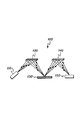
図2は、本発明のXRF/WDSシステムにおいて使用する点間集束を提供する両側湾曲結晶光学部品を示す図で、ヨハン型両側湾曲結晶の幾何形状の一例を示す図である。この幾何形状では、結晶160の回折面は、結晶面と平行に示されている。結晶面は、環状であり、集束円170の面においてヨハン幾何形状を有し、線SIに沿って軸対称である。点SはX線源110(図1)の位置であり、点Iは焦点である。結晶面は、集束円の面において2Rの曲率半径を有し、セグメントSIに垂直な中間面において2Rsin2θBの曲率半径を有する。Rは集束円の半径、θBはブラッグ角である。X線は、点Sから発散して、結晶のロッキング曲線幅の内部にある入射角度で結晶面を打ち、点Iに効率的に反射される。この型の両側湾曲結晶は、ビーム180の点集束だけでなく、単色化も提供するが、その理由は、適切な波長を有するX線光子のみを反射することができるからである。
FIG. 2 is a diagram showing a double-sided curved crystal optic that provides point-to-point focusing for use in the XRF / WDS system of the present invention, showing an example of the geometry of a Johann double-sided curved crystal. In this geometry, the diffractive surface of the
図1に示すように、X線光学部品(x-ray optic)140は、XRFシステム100の他の単色光学要素であり、サンプル130と検出器150との間に配置される。この光学部品は、X線の特有の波長を収集して、そのX線をX線検出器に向ける。従来のXRF/WDSシステムでは、平坦または片側湾曲結晶光学部品を光学部品として選択することが可能である。本発明では、収集モノクロメータは、両側湾曲回折装置(例えば、結晶光学部品または多層光学部品)であり、これは、平坦/片側湾曲光学部品より、点からのはるかに大きな収集立体角を提供することができる。
As shown in FIG. 1,
収集単色光学部品(collection monochromatic optic)140の特有の例は、両側湾曲対数らせん結晶光学部品である。
A particular example of collection
図3Aは、本発明によるXRF/WDSシステムにおいて使用する両側湾曲対数らせん結晶又は多層光学部品の幾何形状の一実施例を示す図で、図3Bは、図3AにおけるB−B線断面図である。 FIG. 3A is a diagram showing an example of the geometry of a double-sided curved logarithmic spiral crystal or multilayer optical component used in the XRF / WDS system according to the present invention, and FIG. 3B is a cross-sectional view taken along line BB in FIG. 3A. .
この幾何形状では、結晶光学部品の回折面は、結晶面に平行である。分散面における結晶面は、対数らせん形状を有し、軸IDに関して回転対称である。点Iは、対数らせんの原点およびサンプル130(図1)の上の励起ビームの焦点であり、点Dは、検出器150(図1)の位置である。サンプルの上の点Iから放出された蛍光X線は、らせん曲線の特性のために、この対数らせん表面に対して一定の入射角を有する。この一定角度は、結晶の回折面について、サンプル130における対象元素の特徴的なX線のブラッグ角度であるように選択される。両側湾曲対数らせん幾何形状から反射されたX線は、点ではなく、分散面において火線を形成する。X線は、図3Bに示すように、IDの方向に沿って軸IDの上に集束する。 In this geometry, the diffractive surface of the crystal optical component is parallel to the crystal plane. The crystal plane in the dispersion plane has a logarithmic spiral shape and is rotationally symmetric with respect to the axis ID. Point I is the origin of the logarithmic helix and the focal point of the excitation beam on the sample 130 (FIG. 1), and point D is the position of the detector 150 (FIG. 1). The fluorescent X-rays emitted from point I above the sample have a constant angle of incidence with respect to this logarithmic helical surface due to the nature of the helical curve. This constant angle is selected to be the characteristic X-ray Bragg angle of the target element in the sample 130 with respect to the diffraction plane of the crystal. X-rays reflected from a bilaterally curved logarithmic spiral geometry form a fire line in the dispersion plane, not a point. The X-rays are focused on the axis ID along the ID direction as shown in FIG. 3B.
他の実施例として、単色光学部品120および収集単色光学部品140の代わりに多層光学部品を、図1のXRF/WDSシステムにおいて使用することが可能である。検出器150は、簡単な計数検出器、すなわち、ガス比例計数管、シンチレーションカウンタ、または室温PINダイオード固体検出器とすることが可能である。
As another example, multilayer optics can be used in the XRF / WDS system of FIG. 1 instead of
XRF/WDSシステム100は、高感度微量元素分析によく適していることが有利である。点間集束両側湾曲結晶光学部品(point-to-point focusing doubly curved crystal)は、大きな収集立体角を提供し、低出力X線管を使用する場合でも、サンプルの上に非常に強い集束単色ビームを形成する。単色励起のために、信号背景比は著しく改善され、検出感度は向上する。励起ビームがサンプルの上に点集束することにより、両側湾曲収集光学部品を効率的に使用して、蛍光X線の収集立体角を改善することが可能になる。これにより、XRF/WDSシステムの感度がさらに向上する。
Advantageously, the XRF /
図1に示したXRF/WDSシステム100の1つの特有の実施例として、このXRF/WDSシステムは、50WのX線管を備えるX線源110を備えることができ、この場合、原材料は、クロム、銅、タングステン、またはモリブデンであり、原材料の上における点のサイズは、約100μmから300μmである。光学部品120は、ケイ素、ゲルマニウム、または他の結晶材料から製造され、かつ光学軸に沿ってX線源110から100mmから200mmに配置された両側湾曲点集束結晶とすることが可能である。光学軸は、両側湾曲結晶120の中心である、両側湾曲結晶120に当たるX線源からの線進行中心として形成される。
As one specific example of the XRF /
サンプル130は、例えば、硫黄、バナジウム、およびニッケルを含む可能性がある微量元素を有する油とすることが可能である。サンプル130は、光学軸に沿って測定して単色光学部品120から100mmから200mmに配置することが可能である。第2単色光学部品140は、ケイ素、ゲルマニウム、または他の結晶材料から製造され、かつ光学軸に沿って測定してサンプル130から100mmから200mmに配置された両側湾曲らせん結晶とすることが可能である。検出器150は、ガス比例計数管、シンチレーションカウンタ、室温PIN検出器、またはNaI検出器とすることが可能であり、光学軸に沿って測定してサンプルから100mmから200mmに配置することが可能である。
Sample 130 may be an oil having trace elements that may include, for example, sulfur, vanadium, and nickel. The sample 130 can be positioned from 100 mm to 200 mm from the monochromatic
1つまたは複数の収集モノクロメータおよび検出器を、XRF/WDSシステム100に追加することによって、2つ以上の元素を検出することができる。各収集モノクロメータは、それぞれの単一元素検出について検出器と対にされる。
By adding one or more acquisition monochromators and detectors to the XRF /
図4は、本発明のXRF/WDSシステムの他の実施例を説明するための構成図で、XRFシステム200の他の実施例を示している。XRF/WDSシステム200は、線源210と、多色集束光学部品220と、サンプル230と、両側湾曲単色光学部品240と、検出器250とから構成されている。
FIG. 4 is a block diagram for explaining another embodiment of the XRF / WDS system of the present invention, and shows another embodiment of the
単色光学部品220は、広範囲の光子エネルギーを伝達する光学要素であり、光子を集束させる間、サンプル230の上の小さいスポットに集中させる。光学部品220として機能するのによく適した多色光学部品の一例は、ニューヨーク州アルバニーのX−Ray Optical Systemsから入手可能なものなど、ポリキャピラリ光学部品300である。
The monochromatic
図5は、本発明のXRF/WDSシステムにおいて使用する点間集束を提供するポリキャピラリ光学部品を示す図である。このポリキャピラリ光学部品300については、上述した特許文献において説明されており、全反射を介して光子を伝達する薄い中空管の束である。
FIG. 5 illustrates a polycapillary optic that provides point-to-point focusing for use in the XRF / WDS system of the present invention. The polycapillary
多色励起のために、信号対背景比は、XRF/WDSシステム100(図1)の信号対背景比と比較して不十分である。しかし、XRF/WDSシステム200(図4)は、いくつかの利点を提供することができる。例えば、XRF/WDSシステム200では、ポリキャピラリ光学部品のより良好な集束能力のために、より小さい集束点を獲得することができる。これは、局所的な分析についてより良好な空間分解能を与える可能性がある。例えば、50WのX線管およびポリキャピラリ光学部品を使用して、20μmから50μmの焦点を獲得することができる。他の利点は、多色励起は、周期表のほとんどすべての元素を網羅することができる広範囲のエネルギーを有するX線光子を提供することができることである。
Due to the multi-color excitation, the signal to background ratio is insufficient compared to the signal to background ratio of the XRF / WDS system 100 (FIG. 1). However, the XRF / WDS system 200 (FIG. 4) can provide several advantages. For example, in the XRF /
1つの特有の実施例では、XRF/WDSシステム200は、50WのX線管とすることが可能であるX線源210を含むことが可能であり、この場合、線源材料は、クロム、銅、タングステン、またはモリブデンであり、対象材料上の点のサイズは、約100μmから300μmである。多色光学部品220は、X線源210から30mmから50mmに配置されたポリキャピラリ光学部品とすることが可能である。
In one particular embodiment, the XRF /
サンプル230は、例えば、硫黄、バナジウム、およびニッケルを含む可能性がある元素を有する油とすることが可能である。サンプル230は、ポリキャピラリ光学部品220から100mmから200mmに配置することができる。両側湾曲モノクロメータ240は、ケイ素、ゲルマニウム、または他の結晶材料から製造され、かつ光学軸に沿って測定してサンプル230から100mmから200mmに配置された両側湾曲対数らせん結晶とすることが可能である。検出器250は、光学軸に沿って測定して単色光学部品240から100mmから200mmに配置されたガス比例計数管、シンチレーションカウンタ、室温PIN検出器、またはNaI検出器とすることができる。対応する検出器を有する複数の収集モノクロメータも、複数元素の検出に使用することができる。
以上、好ましい実施例について説明したが、当業者には、特許請求の範囲に記載された技術的範囲から逸脱せずに、様々な修正、追加、代替実施例が可能であることは明らかである。 While the preferred embodiment has been described above, it will be apparent to those skilled in the art that various modifications, additions, and alternative embodiments can be made without departing from the scope of the claims. .
Claims (32)
サンプルの少なくとも1つの分析物を励起して蛍光発光させるために、前記X線放射源からのX線放射を収集して、該X線放射を前記サンプルの上の焦点に集束させるための、前記X線放射源と前記サンプルとの間に配置された少なくとも1つの励起光学部品と、
少なくとも1つのX線検出器と、
前記サンプルの上の前記焦点からX線蛍光を収集して、該X線蛍光を前記X線検出器に向けるための、前記サンプルと前記X線検出器との間に配置された少なくとも1つの両側湾曲回折光学部品を有する少なくとも1つの収集光学部品と
を備えたことを特徴とするX線蛍光分光システム。 At least one x-ray radiation source;
Collecting X-ray radiation from the X-ray radiation source and focusing the X-ray radiation at a focal point above the sample to excite and fluoresce at least one analyte of the sample; At least one excitation optic disposed between an X-ray radiation source and the sample;
At least one X-ray detector;
At least one side disposed between the sample and the x-ray detector for collecting x-ray fluorescence from the focal point on the sample and directing the x-ray fluorescence to the x-ray detector An X-ray fluorescence spectroscopy system comprising: at least one collection optical component having a curved diffractive optical component.
サンプルの少なくとも1つの分析物を刺激して、蛍光発光させるために、前記X線放射源からのX線放射を収集して、該X線放射を前記サンプルの上の焦点に集束させるための、前記X線放射源と分析される前記サンプルとの間に配置された少なくとも1つの励起光学部品を提供し、
少なくとも1つのX線検出器を提供し、
前記サンプルの上の前記焦点からX線蛍光を収集して、該X線蛍光を前記X線検出器に向けるための、少なくとも1つの両側湾曲回折光学部品を備える少なくとも1つの収集光学部品を、前記サンプルと前記X線検出器との間に配置する
ことを特徴とするX線蛍光分光方法。 Providing at least one X-ray radiation source;
Collecting X-ray radiation from the X-ray radiation source and focusing the X-ray radiation at a focal point above the sample to stimulate and fluoresce at least one analyte of the sample; Providing at least one excitation optic disposed between the X-ray radiation source and the sample to be analyzed;
Providing at least one X-ray detector;
At least one collection optic comprising at least one double-sided curved diffractive optic for collecting x-ray fluorescence from the focal point on the sample and directing the x-ray fluorescence to the x-ray detector; It arrange | positions between a sample and the said X-ray detector. X-ray fluorescence spectroscopy method characterized by the above-mentioned.
Applications Claiming Priority (2)
| Application Number | Priority Date | Filing Date | Title |
|---|---|---|---|
| US29937101P | 2001-06-19 | 2001-06-19 | |
| PCT/US2002/019272 WO2002103710A2 (en) | 2001-06-19 | 2002-06-18 | Wavelength dispersive xrf system using focusing optic for excitation and a focusing monochromator for collection |
Related Child Applications (1)
| Application Number | Title | Priority Date | Filing Date |
|---|---|---|---|
| JP2007271638A Division JP5489401B2 (en) | 2001-06-19 | 2007-10-18 | X-ray fluorescence spectroscopy system and fluorescence x-ray spectroscopy method |
Publications (2)
| Publication Number | Publication Date |
|---|---|
| JP2005512020A true JP2005512020A (en) | 2005-04-28 |
| JP2005512020A5 JP2005512020A5 (en) | 2008-08-14 |
Family
ID=23154489
Family Applications (3)
| Application Number | Title | Priority Date | Filing Date |
|---|---|---|---|
| JP2003505939A Pending JP2005512020A (en) | 2001-06-19 | 2002-06-18 | X-ray fluorescence spectroscopy system and X-ray fluorescence spectroscopy method |
| JP2007271638A Expired - Lifetime JP5489401B2 (en) | 2001-06-19 | 2007-10-18 | X-ray fluorescence spectroscopy system and fluorescence x-ray spectroscopy method |
| JP2013258597A Pending JP2014066731A (en) | 2001-06-19 | 2013-12-13 | Fluorescent x-ray spectroscopy system and fluorescent x-ray spectroscopy method |
Family Applications After (2)
| Application Number | Title | Priority Date | Filing Date |
|---|---|---|---|
| JP2007271638A Expired - Lifetime JP5489401B2 (en) | 2001-06-19 | 2007-10-18 | X-ray fluorescence spectroscopy system and fluorescence x-ray spectroscopy method |
| JP2013258597A Pending JP2014066731A (en) | 2001-06-19 | 2013-12-13 | Fluorescent x-ray spectroscopy system and fluorescent x-ray spectroscopy method |
Country Status (12)
| Country | Link |
|---|---|
| US (1) | US6934359B2 (en) |
| EP (1) | EP1402541B1 (en) |
| JP (3) | JP2005512020A (en) |
| CN (1) | CN1246858C (en) |
| AT (1) | ATE336789T1 (en) |
| AU (1) | AU2002315331A1 (en) |
| CA (1) | CA2489646C (en) |
| DE (1) | DE60213994T2 (en) |
| ES (1) | ES2271277T3 (en) |
| HK (1) | HK1070984A1 (en) |
| RU (1) | RU2339974C2 (en) |
| WO (1) | WO2002103710A2 (en) |
Cited By (6)
| Publication number | Priority date | Publication date | Assignee | Title |
|---|---|---|---|---|
| JP2007093593A (en) * | 2005-09-01 | 2007-04-12 | Japan Science & Technology Agency | Total reflection fluorescent x-ray analysis method and device |
| JP2008180656A (en) * | 2007-01-25 | 2008-08-07 | Tohoku Univ | Non-scanning wavelength-dispersive x-ray spectrometer and measuring method of using the same |
| JP2011505563A (en) * | 2007-11-30 | 2011-02-24 | エックス−レイ オプティカル システムズ インコーポレーテッド | Pre-filmed precision sample cell for X-ray analyzer |
| JP2011513751A (en) * | 2008-03-05 | 2011-04-28 | エックス−レイ オプティカル システムズ インコーポレーテッド | XRF system with multiple excitation energy bands in a highly aligned housing |
| JP2013113782A (en) * | 2011-11-30 | 2013-06-10 | Rigaku Corp | Fluorescence x-ray analyzer |
| JP2014520276A (en) * | 2011-06-20 | 2014-08-21 | エックス−レイ オプティカル システムズ インコーポレーテッド | Online monitoring of pollutants in crude oil and heavy oil and its refinery application |
Families Citing this family (74)
| Publication number | Priority date | Publication date | Assignee | Title |
|---|---|---|---|---|
| US20080220441A1 (en) * | 2001-05-16 | 2008-09-11 | Birnbaum Eva R | Advanced drug development and manufacturing |
| EP1463932B1 (en) * | 2001-11-17 | 2009-07-01 | The Science and Technology Facilities Council | Method and apparatus for obtaining simultaneously x-ray absorption and refraction images by use of a monochromator with integrated radiation detector |
| WO2004001769A1 (en) | 2002-06-19 | 2003-12-31 | Xenocs | Optical device for x-ray applications |
| FR2850171B1 (en) * | 2003-01-21 | 2005-04-08 | Xenocs | OPTICAL DEVICE FOR X-RAY APPLICATIONS |
| DE10254026C5 (en) * | 2002-11-20 | 2009-01-29 | Incoatec Gmbh | Reflector for X-radiation |
| US7763820B1 (en) | 2003-01-27 | 2010-07-27 | Spectramet, Llc | Sorting pieces of material based on photonic emissions resulting from multiple sources of stimuli |
| JP3729203B2 (en) * | 2003-03-27 | 2005-12-21 | 理学電機工業株式会社 | X-ray fluorescence analyzer |
| US7006596B1 (en) * | 2003-05-09 | 2006-02-28 | Kla-Tencor Technologies Corporation | Light element measurement |
| CN101356589B (en) * | 2005-08-01 | 2013-02-27 | 纽约州立大学研究基金会 | X-ray imaging systems employing point-focusing, curved monochromating optics |
| US7991116B2 (en) * | 2005-08-04 | 2011-08-02 | X-Ray Optical Systems, Inc. | Monochromatic x-ray micro beam for trace element mapping |
| US7519153B1 (en) * | 2006-03-24 | 2009-04-14 | Kla-Tencor Technologies Corporation | X-ray metrology with diffractors |
| JP3950156B1 (en) * | 2006-04-11 | 2007-07-25 | 理学電機工業株式会社 | X-ray fluorescence analyzer |
| US7634052B2 (en) * | 2006-10-24 | 2009-12-15 | Thermo Niton Analyzers Llc | Two-stage x-ray concentrator |
| US7412131B2 (en) * | 2007-01-02 | 2008-08-12 | General Electric Company | Multilayer optic device and system and method for making same |
| EP1953537A1 (en) * | 2007-01-30 | 2008-08-06 | KEMMER, Josef, Dr. | Device for detecting or guiding x-radiation using x-ray optics |
| EP2162732A1 (en) * | 2007-03-15 | 2010-03-17 | X-ray Optical Systems, INC. | Small spot and high energy resolution xrf system for valence state determination |
| US7366374B1 (en) | 2007-05-22 | 2008-04-29 | General Electric Company | Multilayer optic device and an imaging system and method using same |
| US20090041198A1 (en) * | 2007-08-07 | 2009-02-12 | General Electric Company | Highly collimated and temporally variable x-ray beams |
| US7508911B1 (en) * | 2007-09-19 | 2009-03-24 | General Electric Company | X-ray imaging system and methods of using and forming an array of optic devices therein |
| US7801272B2 (en) * | 2007-09-28 | 2010-09-21 | Rigaku Corporation | X-ray diffraction apparatus and X-ray diffraction method |
| US7742566B2 (en) * | 2007-12-07 | 2010-06-22 | General Electric Company | Multi-energy imaging system and method using optic devices |
| EP2263238B1 (en) * | 2008-04-11 | 2012-06-20 | Rigaku Innovative Technologies, Inc. | X-ray generator with polycapillary optic |
| CN101581680A (en) * | 2008-12-25 | 2009-11-18 | 中国建筑材料检验认证中心 | Hyperbolic crystal X-ray fluorescence spectrum analyzer and operating method thereof |
| US20100310041A1 (en) * | 2009-06-03 | 2010-12-09 | Adams William L | X-Ray System and Methods with Detector Interior to Focusing Element |
| US8058621B2 (en) * | 2009-10-26 | 2011-11-15 | General Electric Company | Elemental composition detection system and method |
| US8208602B2 (en) * | 2010-02-22 | 2012-06-26 | General Electric Company | High flux photon beams using optic devices |
| US8311184B2 (en) | 2010-08-30 | 2012-11-13 | General Electric Company | Fan-shaped X-ray beam imaging systems employing graded multilayer optic devices |
| US8744048B2 (en) | 2010-12-28 | 2014-06-03 | General Electric Company | Integrated X-ray source having a multilayer total internal reflection optic device |
| US8761346B2 (en) | 2011-07-29 | 2014-06-24 | General Electric Company | Multilayer total internal reflection optic devices and methods of making and using the same |
| JP6175436B2 (en) | 2011-08-06 | 2017-08-02 | リガク イノベイティブ テクノロジーズ インコーポレイテッド | Nanotube material guide for X-ray photons and neutrons |
| EP2745101B1 (en) | 2011-08-15 | 2019-11-06 | X-Ray Optical Systems, Inc. | X-ray analysis apparatus |
| CN103946693B (en) | 2011-10-06 | 2017-05-03 | X射线光学系统公司 | Mobile transport and shielding apparatus for removable x-ray analyzer |
| CN103765201B (en) * | 2011-10-26 | 2017-11-07 | X射线光学系统公司 | The monochromating x-ray optic of the supporting construction and height alignment of X-ray analysis engine and analyzer |
| JP5907375B2 (en) * | 2011-12-28 | 2016-04-26 | 株式会社テクノエックス | X-ray fluorescence analyzer and X-ray fluorescence analysis method |
| EP2820666A4 (en) * | 2012-02-28 | 2016-02-17 | X Ray Optical Sys Inc | X-ray analyzer having multiple excitation energy bands produced using multi-material x-ray tube anodes and monochromating optics |
| CN103018266A (en) * | 2012-12-14 | 2013-04-03 | 上海出入境检验检疫局工业品与原材料检测技术中心 | Method for measuring microelements in lubricating oil by total reflection X-ray fluorescence spectrometry |
| CN103076352B (en) * | 2012-12-28 | 2015-02-25 | 中国科学院高能物理研究所 | Method for obtaining high-quality X-ray absorption spectrum of thin film sample |
| JP6082634B2 (en) * | 2013-03-27 | 2017-02-15 | 株式会社日立ハイテクサイエンス | X-ray fluorescence analyzer |
| WO2015027225A1 (en) | 2013-08-23 | 2015-02-26 | The Schepens Eye Research Institute, Inc. | Spatial modeling of visual fields |
| US10295485B2 (en) | 2013-12-05 | 2019-05-21 | Sigray, Inc. | X-ray transmission spectrometer system |
| USRE48612E1 (en) | 2013-10-31 | 2021-06-29 | Sigray, Inc. | X-ray interferometric imaging system |
| CN103985942B (en) * | 2014-05-15 | 2016-03-30 | 南京航空航天大学 | A kind of rectangular waveguide is to domino plasma waveguide transducer |
| JP6397690B2 (en) * | 2014-08-11 | 2018-09-26 | 株式会社日立ハイテクノロジーズ | X-ray transmission inspection apparatus and foreign object detection method |
| JP6142135B2 (en) * | 2014-12-25 | 2017-06-07 | 株式会社リガク | Obliquely incident X-ray fluorescence analyzer and method |
| JP6069609B2 (en) * | 2015-03-26 | 2017-02-01 | 株式会社リガク | Double-curved X-ray condensing element and its constituent, double-curved X-ray spectroscopic element and method for producing the constituent |
| US11964304B2 (en) | 2015-07-16 | 2024-04-23 | Sortera Technologies, Inc. | Sorting between metal alloys |
| CN108136445B (en) | 2015-07-16 | 2020-11-20 | 索特拉合金有限公司 | Material sorting system |
| US10722922B2 (en) | 2015-07-16 | 2020-07-28 | UHV Technologies, Inc. | Sorting cast and wrought aluminum |
| US10625304B2 (en) | 2017-04-26 | 2020-04-21 | UHV Technologies, Inc. | Recycling coins from scrap |
| US11278937B2 (en) | 2015-07-16 | 2022-03-22 | Sortera Alloys, Inc. | Multiple stage sorting |
| WO2017024035A1 (en) | 2015-08-03 | 2017-02-09 | UHV Technologies, Inc. | Metal analysis during pharmaceutical manufacturing |
| US10677744B1 (en) * | 2016-06-03 | 2020-06-09 | U.S. Department Of Energy | Multi-cone x-ray imaging Bragg crystal spectrometer |
| CN106248706A (en) * | 2016-07-13 | 2016-12-21 | 北京师范大学 | A kind of minisize capillary pipe x-ray lens focuses on the XRF spectrometer of isotope radioactive source |
| JP7418208B2 (en) | 2016-09-15 | 2024-01-19 | ユニバーシティ オブ ワシントン | X-ray spectrometer and its usage |
| WO2018200866A1 (en) | 2017-04-26 | 2018-11-01 | UHV Technologies, Inc. | Material sorting using a vision system |
| CN108802081B (en) * | 2017-04-27 | 2021-07-30 | 北京安科慧生科技有限公司 | X-ray fluorescence (XRF) spectroscopy systems and methods |
| SE544318C2 (en) * | 2018-04-20 | 2022-04-05 | Outotec Finland Oy | X-ray fluorescence analyzer for analysis of small concentrations of element in slurry |
| WO2019236384A1 (en) * | 2018-06-04 | 2019-12-12 | Sigray, Inc. | Wavelength dispersive x-ray spectrometer |
| KR20210028608A (en) * | 2018-07-04 | 2021-03-12 | 가부시키가이샤 리가쿠 | Fluorescence X-ray analysis device |
| WO2020023408A1 (en) | 2018-07-26 | 2020-01-30 | Sigray, Inc. | High brightness x-ray reflection source |
| DE112019004433T5 (en) | 2018-09-04 | 2021-05-20 | Sigray, Inc. | SYSTEM AND PROCEDURE FOR X-RAY FLUORESCENCE WITH FILTERING |
| DE112019004478T5 (en) | 2018-09-07 | 2021-07-08 | Sigray, Inc. | SYSTEM AND PROCEDURE FOR X-RAY ANALYSIS WITH SELECTABLE DEPTH |
| CN109030529B (en) * | 2018-10-30 | 2021-12-21 | 上海爱斯特电子有限公司 | Monochromatic excitation X-ray fluorescence spectrometer |
| DE112020004169T5 (en) | 2019-09-03 | 2022-05-25 | Sigray, Inc. | SYSTEM AND METHODS FOR COMPUTER-ASSISTED LAMINOGRAM X-RAY FLUORESCENCE IMAGING |
| US11175243B1 (en) | 2020-02-06 | 2021-11-16 | Sigray, Inc. | X-ray dark-field in-line inspection for semiconductor samples |
| US11217357B2 (en) | 2020-02-10 | 2022-01-04 | Sigray, Inc. | X-ray mirror optics with multiple hyperboloidal/hyperbolic surface profiles |
| US11215572B2 (en) | 2020-05-18 | 2022-01-04 | Sigray, Inc. | System and method for x-ray absorption spectroscopy using a crystal analyzer and a plurality of detector elements |
| JP7380421B2 (en) * | 2020-05-27 | 2023-11-15 | 株式会社島津製作所 | X-ray analysis device and X-ray analysis method |
| WO2022061347A1 (en) | 2020-09-17 | 2022-03-24 | Sigray, Inc. | System and method using x-rays for depth-resolving metrology and analysis |
| JP7100910B2 (en) * | 2020-12-01 | 2022-07-14 | 株式会社リガク | Total internal reflection fluorescent X-ray analyzer |
| US11686692B2 (en) | 2020-12-07 | 2023-06-27 | Sigray, Inc. | High throughput 3D x-ray imaging system using a transmission x-ray source |
| CN113218975A (en) * | 2021-04-25 | 2021-08-06 | 中科合成油技术有限公司 | Surface X-ray absorption spectrum measuring device |
| US11885755B2 (en) | 2022-05-02 | 2024-01-30 | Sigray, Inc. | X-ray sequential array wavelength dispersive spectrometer |
| US20240035990A1 (en) | 2022-07-29 | 2024-02-01 | X-Ray Optical Systems, Inc. | Polarized, energy dispersive x-ray fluorescence system and method |
Family Cites Families (31)
| Publication number | Priority date | Publication date | Assignee | Title |
|---|---|---|---|---|
| DE3125803A1 (en) * | 1981-06-30 | 1983-01-13 | Siemens AG, 1000 Berlin und 8000 München | CRYSTAL ROENTGEN SEQUENCE SPECTROMETER |
| NL8302263A (en) * | 1983-06-27 | 1985-01-16 | Philips Nv | ROENTGEN ANALYSIS DEVICE WITH DOUBLE CURVED MONOCHROMATOR CRYSTAL. |
| US4599741A (en) * | 1983-11-04 | 1986-07-08 | USC--Dept. of Materials Science | System for local X-ray excitation by monochromatic X-rays |
| JP2742415B2 (en) * | 1987-11-27 | 1998-04-22 | 株式会社日立製作所 | X-ray analyzer |
| NL8801019A (en) * | 1988-04-20 | 1989-11-16 | Philips Nv | ROENTGEN SPECTROMETER WITH DOUBLE-CURVED CRYSTAL. |
| JPH04120500A (en) * | 1990-09-11 | 1992-04-21 | Shimadzu Corp | X-ray monochrome condensor |
| US5192869A (en) * | 1990-10-31 | 1993-03-09 | X-Ray Optical Systems, Inc. | Device for controlling beams of particles, X-ray and gamma quanta |
| US5175755A (en) * | 1990-10-31 | 1992-12-29 | X-Ray Optical System, Inc. | Use of a kumakhov lens for x-ray lithography |
| DE9117302U1 (en) * | 1990-10-31 | 1999-10-21 | X Ray Optical Sys Inc | Device for controlling rays of particles, X-rays and gamma rays and applications thereof |
| US5497008A (en) * | 1990-10-31 | 1996-03-05 | X-Ray Optical Systems, Inc. | Use of a Kumakhov lens in analytic instruments |
| JPH04190148A (en) * | 1990-11-26 | 1992-07-08 | Hitachi Ltd | Method and apparatus for analyzing surface |
| GB2266040B (en) * | 1992-04-09 | 1996-03-13 | Rigaku Ind Corp | X-ray analysis apparatus |
| JP2796067B2 (en) * | 1994-02-08 | 1998-09-10 | 理学電機工業株式会社 | Sample preparation method for X-ray fluorescence analysis |
| JP2728627B2 (en) * | 1994-04-13 | 1998-03-18 | 株式会社神戸製鋼所 | Wavelength dispersive X-ray spectrometer |
| DE69427152T2 (en) * | 1994-07-08 | 2001-11-22 | Muradin Abubekirovic Kumachov | METHOD FOR GUIDING NEUTRAL AND CARGO BEAMS AND A DEVICE FOR IMPLEMENTING THE METHOD |
| US5570408A (en) * | 1995-02-28 | 1996-10-29 | X-Ray Optical Systems, Inc. | High intensity, small diameter x-ray beam, capillary optic system |
| US5604353A (en) * | 1995-06-12 | 1997-02-18 | X-Ray Optical Systems, Inc. | Multiple-channel, total-reflection optic with controllable divergence |
| US5745547A (en) * | 1995-08-04 | 1998-04-28 | X-Ray Optical Systems, Inc. | Multiple channel optic |
| US5982847A (en) * | 1996-10-28 | 1999-11-09 | Utah State University | Compact X-ray fluorescence spectrometer for real-time wear metal analysis of lubrucating oils |
| JPH10227749A (en) * | 1997-02-14 | 1998-08-25 | Matsushita Electric Ind Co Ltd | Radiographic inspection device and method |
| DE69727370T2 (en) * | 1997-06-11 | 2004-12-09 | Istituto Nazionale Di Fisica Nucleare | Multi-stage diffractor made with a constant stage width angle (multi-stage monochromator) |
| US5892809A (en) * | 1997-09-10 | 1999-04-06 | Wittry; David B. | Simplified system for local excitation by monochromatic x-rays |
| JP3604265B2 (en) * | 1997-10-27 | 2004-12-22 | 独立行政法人科学技術振興機構 | X-ray diffraction element and method of manufacturing the same |
| JP2000155102A (en) * | 1998-11-19 | 2000-06-06 | Rigaku Corp | X-ray measuring apparatus and method therefor |
| US6285506B1 (en) * | 1999-01-21 | 2001-09-04 | X-Ray Optical Systems, Inc. | Curved optical device and method of fabrication |
| ATE340478T1 (en) * | 1999-07-21 | 2006-10-15 | Lucent Technologies Inc | TELECOMMUNICATIONS SYSTEM |
| US6381303B1 (en) * | 1999-09-29 | 2002-04-30 | Jordan Valley Applied Radiation Ltd. | X-ray microanalyzer for thin films |
| JP2001124711A (en) * | 1999-10-27 | 2001-05-11 | Fujitsu Ltd | Fluorescence x-ray analysis method and evaluation method of sample structure |
| US6317483B1 (en) * | 1999-11-29 | 2001-11-13 | X-Ray Optical Systems, Inc. | Doubly curved optical device with graded atomic planes |
| US6697454B1 (en) * | 2000-06-29 | 2004-02-24 | X-Ray Optical Systems, Inc. | X-ray analytical techniques applied to combinatorial library screening |
| US6829327B1 (en) * | 2000-09-22 | 2004-12-07 | X-Ray Optical Systems, Inc. | Total-reflection x-ray fluorescence apparatus and method using a doubly-curved optic |
-
2002
- 2002-06-18 CA CA2489646A patent/CA2489646C/en not_active Expired - Lifetime
- 2002-06-18 EP EP02742177A patent/EP1402541B1/en not_active Expired - Lifetime
- 2002-06-18 ES ES02742177T patent/ES2271277T3/en not_active Expired - Lifetime
- 2002-06-18 CN CNB028161939A patent/CN1246858C/en not_active Expired - Lifetime
- 2002-06-18 JP JP2003505939A patent/JP2005512020A/en active Pending
- 2002-06-18 DE DE60213994T patent/DE60213994T2/en not_active Expired - Lifetime
- 2002-06-18 WO PCT/US2002/019272 patent/WO2002103710A2/en active IP Right Grant
- 2002-06-18 RU RU2004101401/28A patent/RU2339974C2/en active
- 2002-06-18 AT AT02742177T patent/ATE336789T1/en active
- 2002-06-18 AU AU2002315331A patent/AU2002315331A1/en not_active Abandoned
-
2003
- 2003-12-19 US US10/742,414 patent/US6934359B2/en not_active Expired - Lifetime
-
2005
- 2005-05-03 HK HK05103722A patent/HK1070984A1/en not_active IP Right Cessation
-
2007
- 2007-10-18 JP JP2007271638A patent/JP5489401B2/en not_active Expired - Lifetime
-
2013
- 2013-12-13 JP JP2013258597A patent/JP2014066731A/en active Pending
Cited By (6)
| Publication number | Priority date | Publication date | Assignee | Title |
|---|---|---|---|---|
| JP2007093593A (en) * | 2005-09-01 | 2007-04-12 | Japan Science & Technology Agency | Total reflection fluorescent x-ray analysis method and device |
| JP2008180656A (en) * | 2007-01-25 | 2008-08-07 | Tohoku Univ | Non-scanning wavelength-dispersive x-ray spectrometer and measuring method of using the same |
| JP2011505563A (en) * | 2007-11-30 | 2011-02-24 | エックス−レイ オプティカル システムズ インコーポレーテッド | Pre-filmed precision sample cell for X-ray analyzer |
| JP2011513751A (en) * | 2008-03-05 | 2011-04-28 | エックス−レイ オプティカル システムズ インコーポレーテッド | XRF system with multiple excitation energy bands in a highly aligned housing |
| JP2014520276A (en) * | 2011-06-20 | 2014-08-21 | エックス−レイ オプティカル システムズ インコーポレーテッド | Online monitoring of pollutants in crude oil and heavy oil and its refinery application |
| JP2013113782A (en) * | 2011-11-30 | 2013-06-10 | Rigaku Corp | Fluorescence x-ray analyzer |
Also Published As
| Publication number | Publication date |
|---|---|
| RU2004101401A (en) | 2005-02-27 |
| EP1402541A2 (en) | 2004-03-31 |
| EP1402541B1 (en) | 2006-08-16 |
| JP5489401B2 (en) | 2014-05-14 |
| CA2489646A1 (en) | 2002-12-27 |
| DE60213994D1 (en) | 2006-09-28 |
| DE60213994T2 (en) | 2006-12-07 |
| JP2014066731A (en) | 2014-04-17 |
| WO2002103710A3 (en) | 2003-05-01 |
| RU2339974C2 (en) | 2008-11-27 |
| JP2008032749A (en) | 2008-02-14 |
| ES2271277T3 (en) | 2007-04-16 |
| HK1070984A1 (en) | 2005-06-30 |
| US20040131146A1 (en) | 2004-07-08 |
| CA2489646C (en) | 2010-02-09 |
| AU2002315331A1 (en) | 2003-01-02 |
| US6934359B2 (en) | 2005-08-23 |
| CN1246858C (en) | 2006-03-22 |
| WO2002103710A2 (en) | 2002-12-27 |
| ATE336789T1 (en) | 2006-09-15 |
| CN1543653A (en) | 2004-11-03 |
Similar Documents
| Publication | Publication Date | Title |
|---|---|---|
| JP5489401B2 (en) | X-ray fluorescence spectroscopy system and fluorescence x-ray spectroscopy method | |
| JP2005512020A5 (en) | ||
| US10295486B2 (en) | Detector for X-rays with high spatial and high spectral resolution | |
| US7899154B2 (en) | Small spot and high energy resolution XRF system for valence state determination | |
| US5497008A (en) | Use of a Kumakhov lens in analytic instruments | |
| US20190011379A1 (en) | Method of performing x-ray spectroscopy and x-ray absorption spectrometer system | |
| US5745543A (en) | Apparatus for simultaneous X-ray diffraction and X-ray fluorescence measurements | |
| US7412030B1 (en) | Apparatus employing conically parallel beam of X-rays | |
| US10256002B2 (en) | Support structure and highly aligned monochromatic X-ray optics for X-ray analysis engines and analyzers | |
| JP7395775B2 (en) | Systems and methods for X-ray absorption spectroscopy using a crystal analyzer and multiple detector elements | |
| WO2013061676A1 (en) | X-ray spectrometry detector device | |
| JP2005527833A (en) | Elemental X-ray fluorescence microscope and method of operation | |
| JP2011513751A (en) | XRF system with multiple excitation energy bands in a highly aligned housing | |
| US9417341B2 (en) | Device and method for determining the energetic composition of electromagnetic waves | |
| JP5990734B2 (en) | X-ray fluorescence analyzer | |
| JP5464419B2 (en) | Spectral crystal, wavelength dispersive X-ray analyzer, and element distribution measurement method | |
| CN109030529A (en) | Monochromatic excitation Xray fluorescence spectrometer | |
| JP6709814B2 (en) | High resolution X-ray diffraction method and apparatus | |
| US20100310041A1 (en) | X-Ray System and Methods with Detector Interior to Focusing Element | |
| CN110621986B (en) | Method of performing x-ray spectral analysis and x-ray absorption spectrometer system | |
| KR20080088057A (en) | A x-ray fluorescence spectrometer | |
| JP2008180656A (en) | Non-scanning wavelength-dispersive x-ray spectrometer and measuring method of using the same | |
| Li et al. | Focal construct geometry for high intensity energy dispersive x-ray diffraction based on x-ray capillary optics |
Legal Events
| Date | Code | Title | Description |
|---|---|---|---|
| A521 | Request for written amendment filed |
Free format text: JAPANESE INTERMEDIATE CODE: A523 Effective date: 20050530 |
|
| A621 | Written request for application examination |
Free format text: JAPANESE INTERMEDIATE CODE: A621 Effective date: 20050530 |
|
| A131 | Notification of reasons for refusal |
Free format text: JAPANESE INTERMEDIATE CODE: A131 Effective date: 20061020 |
|
| A601 | Written request for extension of time |
Free format text: JAPANESE INTERMEDIATE CODE: A601 Effective date: 20070122 |
|
| A602 | Written permission of extension of time |
Free format text: JAPANESE INTERMEDIATE CODE: A602 Effective date: 20070201 |
|
| A521 | Request for written amendment filed |
Free format text: JAPANESE INTERMEDIATE CODE: A523 Effective date: 20070420 |
|
| A02 | Decision of refusal |
Free format text: JAPANESE INTERMEDIATE CODE: A02 Effective date: 20070619 |
|
| RD13 | Notification of appointment of power of sub attorney |
Free format text: JAPANESE INTERMEDIATE CODE: A7433 Effective date: 20070919 |
|
| A521 | Request for written amendment filed |
Free format text: JAPANESE INTERMEDIATE CODE: A821 Effective date: 20070919 |
|
| A521 | Request for written amendment filed |
Free format text: JAPANESE INTERMEDIATE CODE: A523 Effective date: 20071018 |
|
| A911 | Transfer to examiner for re-examination before appeal (zenchi) |
Free format text: JAPANESE INTERMEDIATE CODE: A911 Effective date: 20071030 |
|
| A131 | Notification of reasons for refusal |
Free format text: JAPANESE INTERMEDIATE CODE: A131 Effective date: 20071221 |
|
| A601 | Written request for extension of time |
Free format text: JAPANESE INTERMEDIATE CODE: A601 Effective date: 20080319 |
|
| A602 | Written permission of extension of time |
Free format text: JAPANESE INTERMEDIATE CODE: A602 Effective date: 20080327 |
|
| A601 | Written request for extension of time |
Free format text: JAPANESE INTERMEDIATE CODE: A601 Effective date: 20080421 |
|
| A602 | Written permission of extension of time |
Free format text: JAPANESE INTERMEDIATE CODE: A602 Effective date: 20080428 |
|
| A601 | Written request for extension of time |
Free format text: JAPANESE INTERMEDIATE CODE: A601 Effective date: 20080521 |
|
| A602 | Written permission of extension of time |
Free format text: JAPANESE INTERMEDIATE CODE: A602 Effective date: 20080528 |
|
| A521 | Request for written amendment filed |
Free format text: JAPANESE INTERMEDIATE CODE: A523 Effective date: 20080623 |
|
| A524 | Written submission of copy of amendment under article 19 pct |
Free format text: JAPANESE INTERMEDIATE CODE: A524 Effective date: 20080623 |
|
| A912 | Re-examination (zenchi) completed and case transferred to appeal board |
Free format text: JAPANESE INTERMEDIATE CODE: A912 Effective date: 20080822 |
|
| RD16 | Notification of change of power of sub attorney |
Free format text: JAPANESE INTERMEDIATE CODE: A7431 Effective date: 20101209 |
|
| A521 | Request for written amendment filed |
Free format text: JAPANESE INTERMEDIATE CODE: A821 Effective date: 20101209 |
|
| A601 | Written request for extension of time |
Free format text: JAPANESE INTERMEDIATE CODE: A601 Effective date: 20110407 |
|
| A602 | Written permission of extension of time |
Free format text: JAPANESE INTERMEDIATE CODE: A602 Effective date: 20110412 |
|
| A601 | Written request for extension of time |
Free format text: JAPANESE INTERMEDIATE CODE: A601 Effective date: 20110506 |
|
| A602 | Written permission of extension of time |
Free format text: JAPANESE INTERMEDIATE CODE: A602 Effective date: 20110511 |