JP2005509569A - Inflatable packaging system - Google Patents
Inflatable packaging system Download PDFInfo
- Publication number
- JP2005509569A JP2005509569A JP2003545551A JP2003545551A JP2005509569A JP 2005509569 A JP2005509569 A JP 2005509569A JP 2003545551 A JP2003545551 A JP 2003545551A JP 2003545551 A JP2003545551 A JP 2003545551A JP 2005509569 A JP2005509569 A JP 2005509569A
- Authority
- JP
- Japan
- Prior art keywords
- inflatable
- seal
- layer
- packaging system
- cell
- Prior art date
- Legal status (The legal status is an assumption and is not a legal conclusion. Google has not performed a legal analysis and makes no representation as to the accuracy of the status listed.)
- Pending
Links
Images


Classifications
-
- B—PERFORMING OPERATIONS; TRANSPORTING
- B32—LAYERED PRODUCTS
- B32B—LAYERED PRODUCTS, i.e. PRODUCTS BUILT-UP OF STRATA OF FLAT OR NON-FLAT, e.g. CELLULAR OR HONEYCOMB, FORM
- B32B21/00—Layered products comprising a layer of wood, e.g. wood board, veneer, wood particle board
- B32B21/04—Layered products comprising a layer of wood, e.g. wood board, veneer, wood particle board comprising wood as the main or only constituent of a layer, which is next to another layer of the same or of a different material
- B32B21/08—Layered products comprising a layer of wood, e.g. wood board, veneer, wood particle board comprising wood as the main or only constituent of a layer, which is next to another layer of the same or of a different material of synthetic resin
-
- B—PERFORMING OPERATIONS; TRANSPORTING
- B65—CONVEYING; PACKING; STORING; HANDLING THIN OR FILAMENTARY MATERIAL
- B65D—CONTAINERS FOR STORAGE OR TRANSPORT OF ARTICLES OR MATERIALS, e.g. BAGS, BARRELS, BOTTLES, BOXES, CANS, CARTONS, CRATES, DRUMS, JARS, TANKS, HOPPERS, FORWARDING CONTAINERS; ACCESSORIES, CLOSURES, OR FITTINGS THEREFOR; PACKAGING ELEMENTS; PACKAGES
- B65D81/00—Containers, packaging elements, or packages, for contents presenting particular transport or storage problems, or adapted to be used for non-packaging purposes after removal of contents
- B65D81/02—Containers, packaging elements, or packages, for contents presenting particular transport or storage problems, or adapted to be used for non-packaging purposes after removal of contents specially adapted to protect contents from mechanical damage
- B65D81/05—Containers, packaging elements, or packages, for contents presenting particular transport or storage problems, or adapted to be used for non-packaging purposes after removal of contents specially adapted to protect contents from mechanical damage maintaining contents at spaced relation from package walls, or from other contents
- B65D81/051—Containers, packaging elements, or packages, for contents presenting particular transport or storage problems, or adapted to be used for non-packaging purposes after removal of contents specially adapted to protect contents from mechanical damage maintaining contents at spaced relation from package walls, or from other contents using pillow-like elements filled with cushioning material, e.g. elastic foam, fabric
- B65D81/052—Containers, packaging elements, or packages, for contents presenting particular transport or storage problems, or adapted to be used for non-packaging purposes after removal of contents specially adapted to protect contents from mechanical damage maintaining contents at spaced relation from package walls, or from other contents using pillow-like elements filled with cushioning material, e.g. elastic foam, fabric filled with fluid, e.g. inflatable elements
-
- Y—GENERAL TAGGING OF NEW TECHNOLOGICAL DEVELOPMENTS; GENERAL TAGGING OF CROSS-SECTIONAL TECHNOLOGIES SPANNING OVER SEVERAL SECTIONS OF THE IPC; TECHNICAL SUBJECTS COVERED BY FORMER USPC CROSS-REFERENCE ART COLLECTIONS [XRACs] AND DIGESTS
- Y10—TECHNICAL SUBJECTS COVERED BY FORMER USPC
- Y10S—TECHNICAL SUBJECTS COVERED BY FORMER USPC CROSS-REFERENCE ART COLLECTIONS [XRACs] AND DIGESTS
- Y10S206/00—Special receptacle or package
- Y10S206/821—Stacking member
-
- Y—GENERAL TAGGING OF NEW TECHNOLOGICAL DEVELOPMENTS; GENERAL TAGGING OF CROSS-SECTIONAL TECHNOLOGIES SPANNING OVER SEVERAL SECTIONS OF THE IPC; TECHNICAL SUBJECTS COVERED BY FORMER USPC CROSS-REFERENCE ART COLLECTIONS [XRACs] AND DIGESTS
- Y10—TECHNICAL SUBJECTS COVERED BY FORMER USPC
- Y10T—TECHNICAL SUBJECTS COVERED BY FORMER US CLASSIFICATION
- Y10T428/00—Stock material or miscellaneous articles
- Y10T428/13—Hollow or container type article [e.g., tube, vase, etc.]
- Y10T428/1334—Nonself-supporting tubular film or bag [e.g., pouch, envelope, packet, etc.]
-
- Y—GENERAL TAGGING OF NEW TECHNOLOGICAL DEVELOPMENTS; GENERAL TAGGING OF CROSS-SECTIONAL TECHNOLOGIES SPANNING OVER SEVERAL SECTIONS OF THE IPC; TECHNICAL SUBJECTS COVERED BY FORMER USPC CROSS-REFERENCE ART COLLECTIONS [XRACs] AND DIGESTS
- Y10—TECHNICAL SUBJECTS COVERED BY FORMER USPC
- Y10T—TECHNICAL SUBJECTS COVERED BY FORMER US CLASSIFICATION
- Y10T428/00—Stock material or miscellaneous articles
- Y10T428/13—Hollow or container type article [e.g., tube, vase, etc.]
- Y10T428/1352—Polymer or resin containing [i.e., natural or synthetic]
Abstract
Description
本発明は、一般に、膨張可能なパッケージングに関する。特に、本発明は、周囲保護、完全性、および膨張可能性が向上した、低プロファイル膨張可能パッケージングシステムに関する。 The present invention relates generally to inflatable packaging. In particular, the present invention relates to a low profile inflatable packaging system with improved ambient protection, integrity, and inflatability.
互いに対してシールされて封筒状パッケージを形成する、対向する膨張可能な部材を有する膨張可能なパッケージングシステムは、輸送されるか他の態様で運ばれる比較的平坦なアイテムに保護を提供することが知られている。しかし、既知の膨張可能なパッケージングシステムは、そのようなアイテムに十分な周囲保護を提供しない。周囲保護が向上した膨張可能な封筒状パッケージングシステムが必要である。 An inflatable packaging system having opposing inflatable members that seal against each other to form an envelope package provides protection to relatively flat items that are transported or otherwise carried It has been known. However, known inflatable packaging systems do not provide sufficient ambient protection for such items. There is a need for an inflatable envelope packaging system with improved perimeter protection.
1つの膨張可能な部材用のチェックバルブが知られている。また、多数の膨張可能なセルを有する膨張可能なパッケージングシステムが知られている。パッケージングの1つの領域に漏れが生じた場合にパッケージングシステムの完全性を確実にするために、多セルパッケージングシステムの各膨張可能なセルに容易に組入れることができるチェックバルブが継続して必要である。 A check valve for one inflatable member is known. Inflatable packaging systems having multiple inflatable cells are also known. A check valve that can be easily incorporated into each inflatable cell of a multi-cell packaging system continues to ensure the integrity of the packaging system if a leak occurs in one area of the packaging. is necessary.
共通の膨張ヘッダーから横方向に延在する多数のセルを有する膨張可能なパッケージングシステムは、膨張困難がある。セルが膨張媒体で満たされるにつれて、各セルの幅が減少する。多数のセルの膨張および幅の減少の相加効果により、セルを膨張ヘッダーから分離するシール上の歪みが生じる。この歪みの結果が、膨張媒体がバックリングポイントから遠いセルに移動するのを抑制するか妨げることさえある、膨張ヘッダーのバックリングである。多数のセルへの、ヘッダーを通る膨張媒体用流路を改良するマルチセル膨張可能パッケージングシステムが必要である。 Inflatable packaging systems having a large number of cells extending laterally from a common inflatable header are difficult to inflate. As the cells are filled with the inflation medium, the width of each cell decreases. The additive effect of multiple cell expansion and width reduction creates distortion on the seal that separates the cells from the expansion header. The result of this distortion is an expansion header buckling that may inhibit or even prevent the expansion medium from moving to a cell far from the buckling point. There is a need for a multi-cell inflatable packaging system that improves the flow path for the inflation medium through the header to multiple cells.
本発明の膨張可能なパッケージングシステムは、間隙以外は、それぞれの層の周囲でともにシールされた第1および第2のフィルム層を有する。間隙は、第1のフィルム層と第2のフィルム層との間に画定された内部への膨張媒体の入口として役立つ。間隙と連通するのは、周囲の一部に隣接した、第1および第2のフィルム層の第1のシールによって形成された膨張チャネルである。膨張チャネルは、膨張媒体を複数の膨張可能なセルに搬送し、各膨張可能なセルは、膨張チャネルと連通する。複数の膨張可能なセルは、第1のシールから延在し、かつ第1のシールに対して横方向の、複数の隔置された第2のシールによって形成される。膨張可能なパッケージングシステムは、複数の膨張可能なセルが膨張したときに、膨張チャネルを通る空気流を維持する手段を含む。 The inflatable packaging system of the present invention has first and second film layers that are sealed together around each layer except for the gap. The gap serves as an inlet for the expansion medium into the interior defined between the first film layer and the second film layer. In communication with the gap is an expansion channel formed by the first seals of the first and second film layers adjacent to a portion of the periphery. The inflation channel conveys inflation medium to a plurality of inflatable cells, and each inflatable cell is in communication with the inflation channel. The plurality of inflatable cells are formed by a plurality of spaced second seals extending from the first seal and transverse to the first seal. The inflatable packaging system includes means for maintaining air flow through the inflation channel when a plurality of inflatable cells are inflated.
図面は、本発明の好ましい実施形態を記載するが、説明で示されるように、他の実施形態も企図される。すべての場合において、この開示は、代表によって本発明を提示し、限定によってではない。本発明の原理の範囲および精神の範囲内である多数の他の修正および実施形態が当業者によって考案できることが理解されるべきである。明確にするためにいくつかの部分を拡大する必要があったので、図が同じ割合で描かれていないことに特に留意されたい。実施形態全体を通して、同じ参照番号が同じ要素に用いられる。 Although the drawings describe preferred embodiments of the present invention, other embodiments are contemplated, as indicated in the description. In all cases, this disclosure presents the invention by way of representation and not limitation. It should be understood that numerous other modifications and embodiments can be devised by those skilled in the art which are within the scope and spirit of the principles of the present invention. Note in particular that the figures are not drawn to the same proportions because some parts had to be enlarged for clarity. Throughout the embodiments, the same reference numerals are used for the same elements.
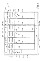
本発明のパッケージングシステム10が、一般に、図1に示されている。パッケージングシステム10は、柔軟性ポリマー材料の、重なる第1の層14および第2の層16(図2を参照のこと)から形成された、膨張可能な部材12から構成される。層14および16の対向する周縁端縁表面は、周囲ヒートシール18によって相互連結される。層14および16の小さい周縁セクション20は、当該技術において一般に知られているようなチェックバルブ22を考慮するために、シールされないままである。適切なチェックバルブが、たとえば、米国特許第4,917,646号明細書および第5,711,691号明細書に開示されている。
A
膨張可能な部材12の3つの側に沿って周囲ヒートシール18から隔置され、ヒートシール24が、層14および16を相互連結して、膨張可能な部材12の周縁の膨張可能な室26を画定し、膨張バルブ22が、膨張可能な室26の第1のセクション27と連通する。層14および16は、ヒートシールセグメント24aとヒートシールセグメント24bとの間に延在するヒートシール28によってさらに相互連結され、パッケージングシステム10の膨張可能な部材12の一連の膨張可能なセル30を画定する。各膨張可能なセル30は、ヒートシールセグメント24aの中断などによって、膨張可能な室26の第1のセクション27と連通する。
Spaced from
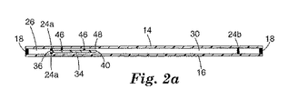
図1〜2aにさらに示されるように、好ましい一実施形態において、膨張可能なセル30および周縁の膨張可能な室26の第2のセクション29は、いったんパッケージングシステム10を膨張させると、それぞれのセルおよび/または室内の空気を保持する一方向バルブシステム32を有する。一方向バルブ32は、本願明細書においてさらに説明される一連のヒートシールで、第3のポリマー層34(図2〜2aに示されている)を第1の層14に連結することによって形成される。
As further shown in FIGS. 1-2a, in a preferred embodiment, the
好ましい一実施形態において、バルブ32は、第1の層14と第2の層16との間に第3の層34を配置することによって形成される。第3の層34は、第1の層14および第2の層16と概ね同じである、端縁36および40で定められた長さを有するが、第3の層34は、第1の層14および第2の層16より小さい、対向する端部端縁42および44で定められた幅を有する。バルブ32は、周縁ヒートシールセグメント18aから第3の層34の端縁36を隔置することによって形成される。次に、端縁36は、ヒートシールセグメント24aによって、第1の層14および第2の層16に対してシールされる。ヒートシールセグメント24aは、第3の層34の端縁36を第2の層16に完全にシールする。しかし、各膨張可能なセル30および膨張可能な室26の第2のセクション29に対応する間隔で、第1の層14または第3の層34の対向表面の一方が、ヒートシールセグメント24aに沿って、耐熱性材料(たとえば、インクまたは塗料)で処理され、処理されたサイトにおいてヒートシーリングを防止し、それにより、空気入口38を画定する。
In a preferred embodiment, the
第3の層34の端縁40は、膨張可能なセル30にわたるヒートシール(以下で説明されるような出口48で中断される)によって、第1の層14に連結される。第3の層34の対向する端部端縁42および44は、ヒートシールによって、それぞれ、周囲ヒートシールセグメント18bおよび18cに沿って、第1の層14および第2の層16に相互連結される。第3の層34は、ヒートシールセグメント24aおよび第3の層34の端縁40に略平行であり、かつ、これらから隔置された一連の熱溶接部46で、第1の層14にさらに連結される。第3の層34または第1の層14の対向表面の一方が、耐熱性材料でさらに処理され、各熱溶接部46に沿ってディスクリートな(discreet)位置において第3の層34および第1の層14の溶接を防止し、入口38から膨張媒体のための蛇行流路を作る。各蛇行流路は、膨張可能な部材12の内部と連通する出口48で終わる。出口48は、端縁40に隣接した第1の層14または第3の層34の一部を、上記のように、耐熱性材料で処理することによって形成される。
The
パッケージングシステム10の膨張可能な部材12は、膨張バルブ22を通して空気を与えることによって膨張される。周縁の膨張可能な室26の第1のセクション27は、入口38を介してバルブ32と連通する。空気は、周縁の膨張可能な室26から、各入口38、およびセグメント化された熱溶接部46で画定されたそれぞれの蛇行流路を通って流れ、出口48を介して、各膨張可能なセル30および周縁の膨張可能な室26のセクション29に入る。膨張可能なセル30および周縁の膨張可能な室26のセクション29が、それらの最大膨張を達成すると、膨張可能なセル30および膨張可能な室26の内圧により、第3の層34および第1の層14の対向表面が、互いに対して密に支持し、それにより、空気が、膨張可能なセル30および周縁の膨張可能な室26から逃げないようにする。
The
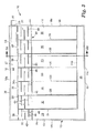
図3〜4aに示されるように、代替実施形態において、バルブ32を、第1の層14の外面35に連結された第3の層34で形成してもよい。この実施形態において、第2の層16は、第1の層14の外面35と反対側の第1の層14の表面37に連結される。図3〜4aに示されるように、第3の層34の端縁36は、周囲ヒートシールセグメント18aに沿って、第1の層14の端縁に対してシールされる。ヒートシールは、第3の層34の端縁40および42を、第1の層14に、さらに連結する。第3の層34の端縁44は、上記のように、膨張媒体入口を画定する小さい周縁セクション20以外は、第1の層14に対してシールされる。
As shown in FIGS. 3-4 a, in an alternative embodiment, the
第2の層16は、周囲ヒートシールセグメント18bおよび18cで定められた長さと、ヒートシールセグメント24aおよび周囲ヒートシールセグメント18dで定められた幅とを有するような寸法である。第2の層16の周囲端縁は、ヒートシールセグメント18b、18c、18d、および24aによって、第1の層14に連結される。ヒートシールセグメント24aは、また、第1の層14および第3の層34を連結し、入口38は、第1の層14または第3の層34の一部を、各セル30に対応する間隔で、耐熱性材料で処理することによって形成され、ヒートシールセグメント24が形成されるときに、第1の層14および第3の層34の隣接した表面のシーリングを防止する。熱溶接部46は、図1に関して説明されたように、第3の層34を第1の層14に相互連結して、バルブ32の蛇行流路を形成する。しかし、出口48は、図3に示された実施形態において、図4aに示されるように、蛇行流路の端部の近くの第1の層14を通る開口部によって形成される。先に説明されたように、膨張可能なセル30および周縁の膨張可能な室26のセクション29が、それらの最大膨張を達成すると、膨張可能なセル30および膨張可能な室26の内圧により、第3の層34および第1の層14の対向表面が、互いに対して密に支持し、それにより、空気が、膨張可能なセル30および周縁の膨張可能な室26から逃げないようにする。
The
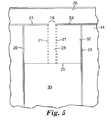
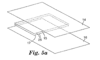
図5は、パッケージングシステム10で使用される一方向バルブ32の代替実施形態を示す。図5は、膨張可能なセル30の1つの拡大破断図である。図5および図5aに示されるように、バルブ32の代替構成は、第1の層14と第2の層16との間に配置された1対のフィルム層15および17からなる。バルブ32の層15および17は、互いに対してシールされ、かつ、ヒートシール28および24によって、第1の層14および第2の層16にシールされる。層15および17の対向する端縁表面は、ゾーン19に沿って耐熱性材料で処理され、ヒートシーリングを防止し、それにより、バルブ32の空気入口を画定する。ヒートシール21は、層15および17をさらに相互連結して、膨張可能なセル30と連通する流路23を画定する。層15および17の対向する端縁25は、シールされないままである。したがって、周縁の膨張可能な室26を通って流れる空気が、ゾーン19で画定された入口を介してバルブ32の流路23に入ることができる。経路23を通って流れる空気は、膨張可能なセル30に入る。膨張可能なセル30が最大膨張に達すると、膨張可能なセル30内の空気圧力が、層15および17が互いに対して密になるように促して、空気が空気経路23を通って逃げないようにし、それにより、膨張可能なセル30を膨張状態に維持する。
FIG. 5 illustrates an alternative embodiment of the one-
一方向バルブ32は、膨張可能な部材12の1つの領域の隔離された空気漏れが、パッケージングシステム10の完全な破滅的な破損をもたらさないことを確実にすることによって、パッケージングシステム10の膨張可能な部材12に完全性を与える。しかし、パッケージングシステム10の膨張可能な部材12は、また、一方向バルブ32を伴わずに使用してもよい。パッケージングシステム10は、さまざまな用途が可能な、単純でしかも洗練された膨張可能なパッケージング材料である。たとえば、壊れやすいかもろい物品を、膨張可能な部材12の多数のセクション間に配置することができる。さらに、膨張可能な部材12のセクションは、輸送用ボックスの内壁をライニングして、もろい内容物を外側のボックス壁から隔離するようなサイズにすることができる。膨張可能な部材12の、さらなる、より新規な用途を、図6〜9を参照して、ここに説明する。
The one-
図6は、低プロファイルのもろいアイテムの輸送用の膨張可能なパッケージ保護システム60を形成する膨張可能な部材12の特に有利な用途の斜視図である。システム60は、一般に、膨張可能な部材12の上部セクション62と、膨張可能な部材12の下部セクション64とから構成される。システム60は、セクション62および64の周縁端縁を垂直に整列させ、セクション62および64の対向する周縁表面領域を3つの側でともに相互連結することによって、形成される。相互連結されたセクション62および64は、組み合わされて封筒状の膨張可能なコンテナを形成し、開端66により、セクション62とセクション64との間で低プロファイルアイテムのアクセスが可能になる。システム60は、膨張状態で示されているが、システム60が収縮状態の間、輸送または保管のために保護が必要なアイテムが、開口部66を通って挿入され、セクション62とセクション64との間に配置されることが理解されるべきである。各セクション62および64は、その後、図1に関して先に説明されたように、膨張バルブ22などの膨張バルブを通して膨張される。膨張可能なセル30の膨張により、セクション62および64の対向する内面が、システム60内に配置された物品に対して密に支持し、アイテムをセクション62とセクション64との間に画定されたポケット内に確実に保持するようにする。セクション62および64の周縁の膨張可能な室26は、特にシステム60が輸送用ボックスまたはコンテナ内に嵌合した場合に、特に適切な周囲保護を提供する。
FIG. 6 is a perspective view of a particularly advantageous application of the
図7は、本質的に図6に示された線7〜7に沿ってとられ、輸送用コンテナ70内にさらに配置されたシステム60の断面図である。図7に示されるように、ヒートシール24(膨張可能な部材12の層14および16を相互連結する)に沿って、セクション62および64の対向表面をともに熱溶接することによって、膨張可能な部材12のセクション62は、膨張可能な部材12のセクション64に相互連結される。1つのセル30または室26の空気漏れの場合に周囲保護を維持するために、セクション62の室26のセクション27は、システム60の一方の側に配置され、セクション64の室26のセクション27は、システム60の他方の側に配置される。セクション62および64がこのように相互連結され、システム60の周縁の膨張可能な室26は、低プロファイルを維持し、かつ、内部ポケットサイズを最大にしながら、重要なコーナおよびアイテムに端縁保護を提供する。システム60内にこのように固定されたアイテム78は、膨張可能なセル30によってその頂部および底部が保護され、膨張可能な周縁室26によってその周縁が保護される。システム60は、それにより、図7に示されるような、額縁、陶磁器皿、またはラップトップコンピュータなどの、もろい低プロファイルアイテムを緩衝し、輸送用コンテナ70の壁からそのようなアイテムを隔置する、低プロファイルの膨張可能なパッケージ保護システムを提供する。
FIG. 7 is a cross-sectional view of
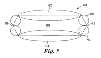
図8は、パッケージングシステム60の代替実施形態の端面図である。図8に示されたパッケージングシステム60の実施形態は、セクション62および64の周縁の膨張可能な室26の対向表面が、ヒートシール18に隣接した膨張可能な部材12の周縁に相互連結される点で、図6および図7に示されたものと異なる。結果として生じるパッケージングシステム60の構成は、それにより、より大きいポケット領域80を組入れ、より大きいアイテムを収容する。
FIG. 8 is an end view of an alternative embodiment of the
対向するセクション62および64の特定の相互連結が、図9に、よりはっきりと示されている。図9に示されるように、周縁の膨張可能な室26の対向表面は、一般に参照番号82で指された接着ゾーンに沿って、相互連結される。一実施形態において、膨張可能な部材12が十分に膨張したとき、接着ゾーン82は、一般に、ヒートシール18から、周縁の膨張可能な室26の半径に概ね対応する距離まで延在する。これは、セクション62を形成する膨張可能な部材12のヒートシール24とセクション64を形成する膨張可能な部材12のヒートシール24との間のより大きい間隔をもたらし、これは、パッケージングシステム60のより大きいポケット80をもたらす。代替実施形態において、接着ゾーン82の位置を変えることによって、ポケット80のサイズを調整することができる。接着ゾーンをヒートシール24のより近くに配置すると、より小さいポケット80をもたらし、逆に、接着ゾーン82をヒートシール18のより近く配置すると、より大きいポケット80をもたらす。図8および図9に示されたように形成されたパッケージングシステム60は、それにより、さまざまな寸法のアイテムを収容することができる。さらに、接着ゾーン82に沿って、セクション62および64(ならびに膨張可能な部材12の付加的なセクション)のそれぞれのセクション26の間に膨張穴22a(図9に点線で示される)を設けることによって、セクション62の膨張可能な部材12を、セクション64の膨張可能な部材12と連通させることが可能である。膨張穴22aを用いることにより、膨張可能な部材12の多数のセクションを、膨張可能な部材12の一方と関連する1つの膨張バルブ22によって膨張させることができる。
The particular interconnection of opposing
図10は、周縁の膨張可能な室26に隣接した二次的な周囲膨張ゾーン25の形成によって、周囲保護がさらに向上した、パッケージングシステム60の別の実施形態の断面図である。周囲膨張ゾーン25は、ヒートシール24から隔置され、かつ、ヒートシール24と略平行である、各層14および16の付加的なヒートシール29によって形成される。ヒートシール29に対応する層14および/または16のセグメントは、ヒートシール29の間隙を形成し、それにより、膨張媒体が膨張可能なセル30および周囲膨張ゾーン25を満たすのを可能にするのに十分な、先に説明された態様で、ヒートシール29に沿って耐熱性材料で処理される。周縁の膨張可能な室26と組み合わされた周囲膨張ゾーン25により、輸送用コンテナ70からのアイテム78の端縁距離が増し、もろいアイテムの周囲端縁のための緩衝が向上する。
FIG. 10 is a cross-sectional view of another embodiment of a
図11は、膨張可能なセル30、および膨張可能なセル30に対して横方向に延在する、周縁の膨張可能な室26の部分に関する、膨張可能な部材12のセグメントの拡大破断図である。図11は、膨張可能な部材12が十分に膨張したときに膨張可能な室26のバックリングを最小にするための周縁の膨張可能な室26の形成の修正を示す。膨張可能な部材12のセル30が膨張すると、膨張可能な部材12の長さLが減少する。この長さの減少に応じて、膨張可能な室26は、膨張可能な部材12の長さLに沿って1以上の位置においてバックリングまたはクリンプする傾向があり、これにより、膨張可能な部材12がその長さに沿ってカールすることがある。膨張可能な室26のこのバックリングまたはクリンピング影響を補償するために、ヒートシールセグメント18aおよび18dに沿って、第1の層14および第2の層16の対向表面のV字形熱溶接部によって、1以上のプリーツ90が形成される。図11に示されるように、プリーツ90は、空気が周縁の膨張可能な室26を通って流れるのを可能にするように、ヒートシール24から十分に隔置されたポイント92まで、ヒートシール18から延在する。プリーツ90は、バックリングしがちな膨張可能な室26の領域において、より均一な周縁形状を維持するように、十分に膨張すると、膨張可能な部材12の長さの減少のために調整するのを助ける。膨張可能な部材12のさまざまな長さおよびサイズに対応するように、プリーツの数およびサイズを変えてもよいことが理解されるべきである。
FIG. 11 is an enlarged cutaway view of a segment of the
新規なパッケージングシステムを、膨張可能な部材12の、2つの相互連結されたセクションから構成されるように、本願明細書において説明したが、ここでの教示を用いて、膨張可能な部材12の3以上のセクションを相互連結することによって、2以上のポケット開口部を有する他のパッケージングシステムを形成してもよいことが理解されるように意図される。パッケージングシステムの共通端部にポケット開口部を配向するように、膨張可能な部材12のセクションを配列および相互連結してもよい。代わりに、膨張可能な部材12の2つの隣接したセクション間に画定された各ポケット開口部の配向を変えるように、膨張可能な部材12のセクションの相互連結部を配置してもよい。
Although a novel packaging system has been described herein as being composed of two interconnected sections of
図12は、図1のシステム10と同様に2つのフィルム層から形成された代替マルチセルパッケージングシステム100の部分上面図である。図12に示されるように、システム100は、複数の膨張可能なセル102を含み、各膨張可能なセル102は、入口105を介して共通の空気通路またはヘッダー104と連通する。ヘッダー104は、2つのフィルム層を相互連結する第1の端縁ヒートシール106および隔置された略平行なヒートシール108によって形成される。ヘッダー104は、空気などの膨張媒体の導入を可能にするために、一端で開いている。代わりに、ヘッダー104は、図1のバルブ22と同様のフィラーバルブ(図示せず)と連通することができる。膨張媒体のヘッダー104への最初の導入から下流のセル102の膨張を容易にするために、ヘッダー104の幅をシステム100の長さに沿って変えてもよく、この場合、ヒートシール106および108は平行ではない。
FIG. 12 is a partial top view of an alternative
入口105は、ヒートシール108を耐熱性材料で作るべき、2つのフィルム層の内面のセクションを、先に説明されたように処理することによって形成される。セル102は、ヒートシール108から延在し、かつ、ヒートシール108に対して横方向である、隔置され、略平行なヒートシール110と、第1の端縁シール106に略平行な第2の端縁ヒートシール112とによって形成される。2つのセル102のみが、図12に示されているが、システム100が、任意の望ましい数のセルを含んでもよいことが理解されるべきである。各セル102の入口105の幅を変えることによって、特定の順序、すなわち、最後から最初、または最初から最後に、セル102を膨張させてもよい。膨張媒体は、最初に、より広い入口を通って流れる。この効果を確かにするために、入口105の幅は、わずか0.0125インチだけ変わってもよい。
The
システム100内のセルの数が増加するにつれて、下流セル102を膨張させる能力が、著しく影響されることがあり、というのは、最初のセル102が膨張し、システム100の長さLを短くするからである。このようにセル102の膨張によってシステム100が短くなることにより、シール108に沿って歪みが生じ、これにより、下流セルへの空気流れの遮断をもたらすことがある、ヘッダーのバックリングまたはしわが生じる。このバックリング傾向を軽減するために、好ましい一実施形態において、各セル102は、シール110および108の交点に隣接して、ヒートシール110とヒートシール108との間にある角度で延在する、1対のヒートシール114を含むように形成される。図12に見られるように、シール114、110、および108は、領域116を隔離し、次に、領域116は、切取られ、除去され、ヘッダー104の近くで隣接したセル102間に空隙を形成する。これらの切取り部分は、シール108に沿った歪みを軽減し、ヘッダーのバックリングを十分に低減して、システム100の下流セル102への、ヘッダーを通る適切な空気流れを確実にする。
As the number of cells in the
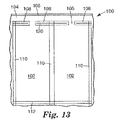
図13に示されるように、システム100の第1の代替実施形態は、セル102が膨張すると、ヘッダーのバックリング影響を低減することが示される。図13の実施形態によれば、ヒートシール110は、ヒートシール108を二分する。次に、ヒートシール108の各セグメントには、スリット120が設けられ、スリット120は、セル102の、膨張により誘起された寸法変化を、ヘッダー104から隔離し、シール108に沿ってバックリング影響を軽減する。
As shown in FIG. 13, a first alternative embodiment of the
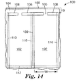
システム100の第2の代替実施形態が、図14に示されている。図14に示されるように、システム100は、収縮状態である。隣接したセル102を分離する各ヒートシール110には、シール108とシール112との間に延在する中央カット130が設けられている。この中央カット130により、各セル102の幅Wが、セル102が膨張すると個別に減少することができ、隣接したセル102間の間隙がカット130に沿って形成される。したがって、カット130は、シール108に沿った歪みを軽減し、ヘッダー104がバックリングしないようにする。
A second alternative embodiment of the
システム100の各セル102は、また、図1〜5aに関して説明された一方向バルブ32のような一方向バルブを組入れてもよい。そのような場合、カット130を、シール106および112を越えて延ばすことなどによって、システム100の連続性を破壊せずに、個別の膨張したセル102をシステム100から切離すことができる。このように、システム100は、異なるサイズの物体を収容するために、任意の望ましい数のセル102で画定された長さを有することができる。システム100は、膨張させ、輸送用コンテナまたはボックス内で輸送されるべき物体の周りに巻くことができる。いったん膨張すると、付加的な個別のセル102は、システム100から分離し、輸送用コンテナの残りの空隙を満たすように使用することができる。システム100は、たとえば、複数のセル102のロールで形成してもよい。セル102の所望の数を選択し、ロールから切離し、図14に示されるように、シールされていないヘッダー104をもたらしてもよい。そのような場合、ヘッダー104の一端でのシール106とシール108との間の間隙Gは、ヒートシールで永久的に閉じられるか、選択されたセル102の膨張前にクランプで一時的に閉じられる。
Each
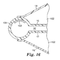
図15および図16は、図5〜5aに関して先に説明された一方向バルブ32を組入れたシステム100の断面図である。図15および図16に示されるように、ヘッダー104は、図15および図16に示されるように材料の連続シートであってもよい、バルブ32の層15および17によって形成される。図15において、層14および16は、ヒートシール108に沿って層15および17にヒートシールされて示されている。入口105の位置における層15および17のシーリングを防止するために、層15上の耐熱性材料層140などの耐熱性材料が、入口105の位置に付与される。図16に示されるように、代わりに、層14および16を、ヘッダー104に隣接した層15および17の表面に対してシールすることができる。ヘッダー104に沿って層15および17のシーリングを防止するために、耐熱性材料層142が、ヘッダー104に沿って層15および/または17に付与される。図15の実施形態は、図12〜14に示されたシステム100の実施形態のいずれかで使用してもよく、一方、図16の実施形態は、図14に示されたシステム100の実施形態で使用するのに特に適している。図15および図16の実施形態により、その後、膨張可能なセル102に対応する構造と組み合わせて、任意の所望の長さのシステム100を形成することができる、1つの構造におけるヘッダーおよび一方向バルブ32の形成が可能になる。
15 and 16 are cross-sectional views of
本発明を好ましい実施形態に関して説明したが、当業者は、本発明の精神および範囲から逸脱することなく、形態および詳細に変更がなされてもよいことを認識するであろう。また、さまざまな実施形態の対応する特徴を交換することによって、本発明のさまざまな変形が可能である。 Although the present invention has been described with reference to preferred embodiments, workers skilled in the art will recognize that changes may be made in form and detail without departing from the spirit and scope of the invention. Also, various modifications of the invention are possible by exchanging corresponding features of the various embodiments.
Claims (5)
前記複数の膨張可能なセルが膨張するときに、前記膨張チャネルを通る空気流を維持する手段を具備する、改良されたパッケージングシステム。 First and second film layers disposed in an overlapping manner, except for a gap of sufficient size to introduce an expansion medium into an interior defined between the first and second film layers. The first and second film layers integrally connected along the periphery of the first and second layers by a perimeter seal; and the first and second film layers adjacent to a portion of the periphery. A plurality of discrete channels formed by one seal and in fluid communication with the gap and a plurality of spaced second seals extending laterally from the first seal and in fluid communication with the expansion channel. A multi-chamber inflatable packaging system comprising:
An improved packaging system comprising means for maintaining an air flow through the inflation channel when the plurality of inflatable cells are inflated.
前記第1シールと各々の前記第2シールとの間の、前記第1および第2フィルム層のコーナシールを含み、前記コーナシールが、前記膨張チャネルおよび各膨張可能なセルとの流体連通から前記第1および第2フィルム層の一部を隔離し、該一部がその後に除去されて空隙を形成するようになっている、請求項1に記載のパッケージングシステム。 Means for maintaining the air flow;
Including a corner seal of the first and second film layers between the first seal and each of the second seals, wherein the corner seal is in fluid communication with the expansion channel and each inflatable cell. The packaging system of claim 1, wherein a portion of the first and second film layers is isolated and the portion is subsequently removed to form a void.
Applications Claiming Priority (2)
| Application Number | Priority Date | Filing Date | Title |
|---|---|---|---|
| US33218501P | 2001-11-16 | 2001-11-16 | |
| PCT/US2002/036986 WO2003043902A1 (en) | 2001-11-16 | 2002-11-15 | Inflatable packaging system |
Publications (2)
| Publication Number | Publication Date |
|---|---|
| JP2005509569A true JP2005509569A (en) | 2005-04-14 |
| JP2005509569A5 JP2005509569A5 (en) | 2006-01-05 |
Family
ID=23297085
Family Applications (3)
| Application Number | Title | Priority Date | Filing Date |
|---|---|---|---|
| JP2003545550A Pending JP2005509568A (en) | 2001-11-16 | 2002-11-15 | One-way valve for inflatable package |
| JP2003545552A Expired - Fee Related JP4116559B2 (en) | 2001-11-16 | 2002-11-15 | Low profile inflatable package protection system |
| JP2003545551A Pending JP2005509569A (en) | 2001-11-16 | 2002-11-15 | Inflatable packaging system |
Family Applications Before (2)
| Application Number | Title | Priority Date | Filing Date |
|---|---|---|---|
| JP2003545550A Pending JP2005509568A (en) | 2001-11-16 | 2002-11-15 | One-way valve for inflatable package |
| JP2003545552A Expired - Fee Related JP4116559B2 (en) | 2001-11-16 | 2002-11-15 | Low profile inflatable package protection system |
Country Status (7)
| Country | Link |
|---|---|
| US (4) | US6978893B2 (en) |
| EP (3) | EP1446334B1 (en) |
| JP (3) | JP2005509568A (en) |
| AT (3) | ATE308467T1 (en) |
| AU (3) | AU2002366049A1 (en) |
| DE (3) | DE60209259T2 (en) |
| WO (3) | WO2003043903A1 (en) |
Cited By (1)
| Publication number | Priority date | Publication date | Assignee | Title |
|---|---|---|---|---|
| JP2013180812A (en) * | 2012-03-02 | 2013-09-12 | Toppan Printing Co Ltd | Cushioning material |
Families Citing this family (132)
| Publication number | Priority date | Publication date | Assignee | Title |
|---|---|---|---|---|
| US7338069B2 (en) * | 2004-04-02 | 2008-03-04 | Automotive Technologies International, Inc. | Airbags with internal valves |
| JP3862536B2 (en) * | 2001-10-02 | 2006-12-27 | 三洋エンジニアリング株式会社 | Packaging structure |
| JP2005509568A (en) * | 2001-11-16 | 2005-04-14 | スリーエム イノベイティブ プロパティズ カンパニー | One-way valve for inflatable package |
| MXPA04008909A (en) | 2002-03-12 | 2005-09-08 | Inflatable Packaging Inc | Inflatable dunnage bag with protected inflator valve. |
| WO2004022449A1 (en) * | 2002-09-04 | 2004-03-18 | Sun A. Kaken Co., Ltd. | Cushioning packaging body containing packaged article, and method and device for manufacturing the packaging body |
| US20050006271A1 (en) * | 2003-06-05 | 2005-01-13 | Noriyuki Nakagawa | Packaging |
| TWM246317U (en) * | 2003-11-19 | 2004-10-11 | Camry Packing Ind Ltd | Air packing bag |
| JP4512375B2 (en) * | 2004-01-08 | 2010-07-28 | 株式会社リコー | Gas bag type packaging material for office equipment and office equipment and packaging method |
| TWM249912U (en) * | 2004-02-18 | 2004-11-11 | Camry Packing Ind Ltd | A valve of air packing bag |
| TWM252680U (en) * | 2004-03-01 | 2004-12-11 | Camry Packing Ind Ltd | Air packing bag having film valve |
| WO2005090197A1 (en) * | 2004-03-24 | 2005-09-29 | Chi Yin Mak | Packaging device and method |
| US7000767B2 (en) * | 2004-05-26 | 2006-02-21 | Air-Paq, Inc. | Structure of air-packing device having improved shock absorbing capability |
| US7897219B2 (en) | 2004-06-01 | 2011-03-01 | Automated Packaging Systems, Inc. | Web and method for making fluid filled units |
| ES2608877T3 (en) | 2004-06-01 | 2017-04-17 | Automated Packaging Systems, Inc | Band and procedure to perform fluid-filled units |
| US20060093763A1 (en) * | 2004-06-30 | 2006-05-04 | Yasusumi Tanaka | Gas hermetic bag packaging material and advertisement medium |
| US7165677B2 (en) * | 2004-08-10 | 2007-01-23 | Air-Paq, Inc. | Structure of air-packing device |
| US20060045392A1 (en) * | 2004-08-16 | 2006-03-02 | Roger Bannister | Transversely sealed container |
| US7254932B2 (en) * | 2004-11-18 | 2007-08-14 | Air-Paq, Inc. | Multi-purpose air-packing method and system |
| WO2006058172A2 (en) * | 2004-11-24 | 2006-06-01 | Built Ny, Inc. | Carry device |
| US20060185998A1 (en) * | 2005-01-29 | 2006-08-24 | Mcgrail Daniel | Inflatable shipping device and method of forming and using same |
| US7735643B2 (en) * | 2005-01-29 | 2010-06-15 | David Sanches | Inflatable shipping device and method of forming and using same |
| US7621104B2 (en) * | 2005-01-31 | 2009-11-24 | Sealed Air Corporation (Us) | Inflatable mailer, apparatus and method for preparing the same |
| US7482051B2 (en) * | 2005-04-11 | 2009-01-27 | Air-Paq, Inc. | Structure of inflatable air-packing device having check valve and multiple air bubbles |
| US7131805B1 (en) * | 2005-04-22 | 2006-11-07 | Coors Global Properties, Inc. | Inflatable cargo cover and method of covering cargo |
| US20090217997A1 (en) * | 2005-05-04 | 2009-09-03 | Alan Feinerman | Thin welded sheets fluid pathway |
| US7862870B2 (en) * | 2005-05-06 | 2011-01-04 | Pregis Innovative Packaging, Inc. | Films for inflatable cushions |
| US7445117B2 (en) * | 2005-09-19 | 2008-11-04 | Air-Paq, Inc. | Structure of air-packing device |
| US20080256901A1 (en) * | 2005-10-24 | 2008-10-23 | Reynolds Foil Inc, D/B/A Reynolds Consumer Products Company | Polymeric package with resealable closure and valve, and methods |
| JP4684079B2 (en) | 2005-10-25 | 2011-05-18 | 東洋自動機株式会社 | Bag with airbag, method for manufacturing the same, method for enclosing gas in bag with airbag, and method for packaging bag with airbag |
| AT503164B1 (en) * | 2006-02-10 | 2007-11-15 | Mam Babyartikel | FREEZE BAG |
| DE202006002934U1 (en) * | 2006-02-23 | 2006-04-20 | Leadpak Industrial Co., Ltd. | Inflatable packaging bag |
| US7448495B2 (en) * | 2006-02-24 | 2008-11-11 | Bbs Licensing, Inc. | Impact resistant cushion for electronic equipment with diagonal corner support and carrying cases including the same |
| US7422109B2 (en) * | 2006-04-25 | 2008-09-09 | Air-Paq, Inc. | Structure of air-packing device |
| TW200812877A (en) * | 2006-09-07 | 2008-03-16 | Yao-Sin Liao | Heterogeneous compound substrate for gas sealing member |
| TWM310867U (en) * | 2006-11-24 | 2007-05-01 | Yao-Sin Liao | Air-sealed body equipped with cut-hole type air check valve, and the cut-hole type air check valve |
| US7857514B2 (en) | 2006-12-12 | 2010-12-28 | Reynolds Foil Inc. | Resealable closures, polymeric packages and systems and methods relating thereto |
| US20080175522A1 (en) * | 2007-01-18 | 2008-07-24 | Chin-Hsin Chuang | Packing bag having a drawing structure |
| US7972063B1 (en) * | 2007-02-20 | 2011-07-05 | Quarter Moon Properties, LLC | Inflatable beverage insulator |
| TWM327855U (en) * | 2007-08-23 | 2008-03-01 | Chieh-Hua Liao | Air-sealing body structure of multi-stage gripping type |
| EP2209614B1 (en) | 2007-10-31 | 2015-08-19 | Automated Packaging Systems, Inc. | Web and method for making fluid filled units |
| CN101430480A (en) * | 2007-11-06 | 2009-05-13 | 鸿富锦精密工业(深圳)有限公司 | Camera case |
| WO2009088757A1 (en) * | 2007-12-31 | 2009-07-16 | 3M Innovative Properties Company | Medical dressing with edge port and methods of use |
| US20110127189A1 (en) * | 2008-01-04 | 2011-06-02 | Liao, Chieh Hua | Bendable multi-sectional cushioning cover bag |
| TW200930632A (en) * | 2008-01-04 | 2009-07-16 | Chieh-Hua Liao | Foldable multi-section buffer packaging bag |
| US7631762B2 (en) * | 2008-01-30 | 2009-12-15 | Chieh Hua LIAO | Hammock-type vibration-absorbing air sheath |
| CN101549774B (en) * | 2008-03-31 | 2013-09-18 | 上海尼禄国际贸易有限公司 | Air packing device and production method thereof |
| EP2265234A4 (en) * | 2008-04-04 | 2011-08-31 | 3M Innovative Properties Co | Medical dressings with valve and kits containing same |
| US9981722B2 (en) * | 2008-05-16 | 2018-05-29 | Joseph Carcamo | Hinged inflatable surfboard cover |
| CN102131715B (en) | 2008-08-25 | 2013-01-02 | 因蒂斯航空股份有限公司 | Air bag with continuous heat resistance material |
| US20100215293A1 (en) | 2008-08-25 | 2010-08-26 | Indis Air Corp | Air bag with pressurization space |
| US8272510B2 (en) * | 2008-10-22 | 2012-09-25 | Sealed Air Corporation (Us) | Inflatable structure for packaging and associated apparatus and method |
| US9085405B2 (en) | 2008-10-22 | 2015-07-21 | Sealed Air Corporation (Us) | Inflatable structure for packaging and associated apparatus and methods |
| US9004758B2 (en) * | 2008-10-22 | 2015-04-14 | Sealed Air Corporation (Us) | Inflatable structure for packaging and associated apparatus and method |
| KR101256701B1 (en) * | 2009-01-05 | 2013-04-19 | 오계술 | Packaging device filled with air |
| NL1036607C2 (en) * | 2009-02-20 | 2010-08-24 | Heijden Nederland Verpakking B V V D | INFLATABLE PACKAGING. |
| US9205622B2 (en) | 2009-02-27 | 2015-12-08 | Automated Packaging Systems, Inc. | Web and method for making fluid filled units |
| US8568029B2 (en) * | 2009-05-05 | 2013-10-29 | Sealed Air Corporation (Us) | Inflatable mailer, apparatus, and method for making the same |
| EP2442770B1 (en) * | 2009-06-16 | 2016-03-30 | 3M Innovative Properties Company | Conformable medical dressing with self supporting substrate |
| CN104960772B (en) * | 2009-08-14 | 2017-10-20 | 上海艾尔贝包装科技发展有限公司 | A kind of air-packing device and its application method with transverse air valves |
| JP5595718B2 (en) * | 2009-11-26 | 2014-09-24 | 克敏 吉房 | Air cell cushioning material |
| GB2477495A (en) * | 2010-02-01 | 2011-08-10 | Sky Packaging Ltd | Inflatable cushions |
| WO2011105999A1 (en) * | 2010-02-24 | 2011-09-01 | Michael Baines | Packaging materials and methods |
| US9623622B2 (en) | 2010-02-24 | 2017-04-18 | Michael Baines | Packaging materials and methods |
| US8201690B1 (en) * | 2010-06-04 | 2012-06-19 | Gess Larry C | End user filled protective packaging with self-sealing air bubbles |
| US8215487B1 (en) * | 2010-10-30 | 2012-07-10 | Gess Larry C | Inflatable packaging with self-sealing air bubbles |
| US8192120B1 (en) | 2010-10-30 | 2012-06-05 | Gess Larry C | Self-sealing inflatable dunnage bag |
| US20130248527A1 (en) * | 2010-12-09 | 2013-09-26 | Food Cradle ApS | Packaging system for food articles |
| AU2012278849B2 (en) | 2011-07-07 | 2016-12-22 | Automated Packaging Systems, Inc. | Air cushion inflation machine |
| US8459915B1 (en) | 2011-09-22 | 2013-06-11 | Ivex Protective Packaging, Inc. | End user filled self-sealing inflatable dunnage bag |
| US8372507B1 (en) * | 2011-09-24 | 2013-02-12 | Ivex Protective Packaging, Inc. | End user filled protective packaging with self-sealing air bubbles |
| WO2013088372A1 (en) | 2011-12-12 | 2013-06-20 | Bag Pack (B.P.) Ltd. | Inflated package, precursor and method |
| TW201323755A (en) | 2011-12-15 | 2013-06-16 | Air Bag Packing Co Ltd | Nonlinear stop valve structure |
| JP2013189237A (en) * | 2012-03-15 | 2013-09-26 | Toshiko Takenaka | Packing material and packing method |
| WO2013169684A1 (en) | 2012-05-07 | 2013-11-14 | The Procter & Gamble Company | Flexible containers having a decoration panel |
| CN104284778B (en) | 2012-05-07 | 2017-12-29 | 宝洁公司 | Flexible material for flexible container |
| CN104284844B (en) * | 2012-05-07 | 2017-10-24 | 宝洁公司 | Flexible container |
| ITEN20120004A1 (en) * | 2012-07-30 | 2014-01-31 | Giuseppe Dainotti | "PRESSURIZED SYSTEM" INFLATABLE CUSHIONS FOR PACKAGING |
| CN104603021B (en) | 2012-08-06 | 2019-08-06 | 宝洁公司 | The method for manufacturing flexible container |
| CN103662407B (en) * | 2012-09-07 | 2015-08-12 | 苏州亚比斯复合材料有限公司 | A kind of mouth blows formula air sealing body |
| CN103029892A (en) * | 2012-12-17 | 2013-04-10 | 上海艾尔贝包装科技发展有限公司 | Exhaust bag and manufacture method thereof |
| US8978693B2 (en) | 2013-01-28 | 2015-03-17 | Windcatcher Technology LLC | Inflation valve allowing for rapid inflation and deflation of an inflatable object |
| MX2015011259A (en) | 2013-03-15 | 2016-02-03 | Automated Packaging Syst Inc | On-demand inflatable packaging. |
| US9969136B2 (en) | 2013-04-19 | 2018-05-15 | Sealed Air Corporation (Us) | Inflatable pouches |
| WO2014190172A1 (en) * | 2013-05-22 | 2014-11-27 | Gess Larry C | Inflatable protective packaging with self-sealing fill channel |
| WO2014199368A1 (en) | 2013-06-12 | 2014-12-18 | Bag Pack (B.P.) Ltd. | Inflator device and method for inflatable packaging |
| US9321236B2 (en) | 2013-06-25 | 2016-04-26 | Sealed Air Corporation (Us) | Automated inflation device |
| BR112016002170A2 (en) | 2013-08-01 | 2017-08-01 | Procter & Gamble | improvements in tactile interaction with film packaging with air-bearing structural support volumes |
| JP2016525050A (en) | 2013-08-01 | 2016-08-22 | ザ プロクター アンド ギャンブル カンパニー | Method for forming flexible container |
| US9688459B2 (en) | 2013-08-01 | 2017-06-27 | The Procter & Gamble Company | Disposable flexible containers having surface elements |
| MX371013B (en) | 2013-08-01 | 2020-01-10 | Procter & Gamble | Flexible containers having improved seam and methods of making the same. |
| EP3066021B1 (en) | 2013-11-06 | 2018-02-14 | The Procter and Gamble Company | Flexible containers and methods of forming the same |
| CN105705431B (en) | 2013-11-06 | 2018-02-23 | 宝洁公司 | Flexible container and the method for forming the flexible container |
| CN105764808A (en) * | 2013-11-06 | 2016-07-13 | 宝洁公司 | Easy-to-empty flexible containers |
| RU2016112351A (en) | 2013-11-06 | 2017-12-11 | Дзе Проктер Энд Гэмбл Компани | Elastic containers and methods for their manufacture |
| JP2016534949A (en) | 2013-11-06 | 2016-11-10 | ザ プロクター アンド ギャンブル カンパニー | A container having a product volume and a stand-off structure connected thereto |
| CA2927199C (en) * | 2013-11-06 | 2019-06-18 | The Procter & Gamble Company | Flexible containers having flexible valves |
| JP2016540702A (en) | 2013-11-06 | 2016-12-28 | ザ プロクター アンド ギャンブル カンパニー | Flexible container for use with short shelf life products and method for facilitating the distribution of flexible containers |
| US9850046B2 (en) * | 2013-11-06 | 2017-12-26 | The Procter & Gamble Company | Flexible containers with vent systems |
| WO2015069821A1 (en) | 2013-11-06 | 2015-05-14 | The Procter & Gamble Company | Flexible containers and methods of making the same |
| CA2931243A1 (en) | 2013-11-21 | 2015-05-28 | Automated Packaging Systems, Inc. | Air cushion inflation machine |
| US9637275B2 (en) | 2014-01-30 | 2017-05-02 | Reusable Solutions Group, Inc. | Reusable shipping container with integrated content protection |
| JP6445281B2 (en) | 2014-09-01 | 2018-12-26 | 克敏 吉房 | Gas cushion material |
| US10112741B2 (en) | 2014-11-10 | 2018-10-30 | Pregis Innovative Packaging Llc | Inflatable packaging with adhesive seals |
| JP2017537853A (en) | 2014-12-19 | 2017-12-21 | ザ プロクター アンド ギャンブル カンパニー | Flexible container lineup |
| US20160176583A1 (en) | 2014-12-19 | 2016-06-23 | The Procter & Gamble Company | Flexible Containers with Easily Variable Sizing |
| CN107000912B (en) | 2014-12-19 | 2018-12-04 | 宝洁公司 | It is easy to change the flexible container of size |
| CN105292768B (en) * | 2014-12-31 | 2019-02-22 | 聂会平 | Fluid container and its shut-off valve and manufacturing method |
| CN104724393B (en) * | 2015-03-06 | 2017-09-22 | 王兴明 | A kind of air bag of the inflation road without hot trace |
| CN107848684B (en) | 2015-04-10 | 2019-10-18 | 宝洁公司 | Flexible container with corrugated turning |
| WO2016164681A1 (en) | 2015-04-10 | 2016-10-13 | The Procter & Gamble Company | Flexible containers with intermediate bottom members |
| US9896253B2 (en) | 2015-04-10 | 2018-02-20 | The Procter & Gamble Company | Flexible containers with reinforcing seals |
| EP3280656B1 (en) | 2015-04-10 | 2019-07-24 | The Procter and Gamble Company | Flexible containers with product dispensing visibility |
| CN107406184B (en) | 2015-04-10 | 2019-07-12 | 宝洁公司 | Flexible container with integral dispensing jet pipe |
| US10850907B2 (en) * | 2015-06-17 | 2020-12-01 | Shanghai Air-Paq Composite Material Co., Ltd. | Air-filling packaging apparatus |
| US11013678B2 (en) | 2015-06-29 | 2021-05-25 | The Procter & Gamble Company | Multi-component skin care product |
| BR112017028461A2 (en) | 2015-06-30 | 2018-08-28 | Procter & Gamble | flexible containers with removable portions |
| US10457457B2 (en) | 2016-04-26 | 2019-10-29 | The Procter & Gamble Company | Flexible containers with bottom support structure |
| US10183785B2 (en) | 2016-04-26 | 2019-01-22 | The Proctor & Gamble Company | Flexible containers with venting structure |
| CN108001855A (en) * | 2016-11-02 | 2018-05-08 | 上海艾尔贝包装科技发展有限公司 | Valveless film air bag and preparation method thereof and aerating device |
| CN110198832B (en) | 2017-02-21 | 2021-07-09 | 宝洁公司 | Method for making an open-celled flexible container |
| CN110225865B (en) | 2017-02-22 | 2021-12-31 | 宝洁公司 | Method of making a flexible container having a structural support frame |
| US20180257836A1 (en) | 2017-03-08 | 2018-09-13 | The Procter & Gamble Company | Flexible containers with graphics of rigid containers |
| US20180297725A1 (en) | 2017-03-24 | 2018-10-18 | The Procter & Gamble Company | Methods of opening flexible containers |
| US10836528B2 (en) | 2017-04-27 | 2020-11-17 | The Procter & Gamble Company | Methods of sealing flexible containers with expansion materials |
| US10640247B2 (en) | 2017-04-27 | 2020-05-05 | The Procter & Gamble Company | Methods of adding expansion material to flexible containers |
| US20190352033A1 (en) * | 2018-05-16 | 2019-11-21 | The Procter & Gamble Company | Method of Performing a Task in Registration With a Seal In Materials and Flexible Containers Made By Method |
| US11338975B2 (en) * | 2018-05-16 | 2022-05-24 | The Procter & Gamble Company | Container blanks for flexible packages and methods of making flexible packages |
| CN108820554B (en) * | 2018-06-12 | 2019-08-16 | 安徽农之源生态农业有限公司 | A kind of pot flowers transport case |
| US11851260B2 (en) * | 2018-07-23 | 2023-12-26 | Pregis Innovative Packaging Llc | Automatic protective packaging inflator |
| CN110159909A (en) * | 2019-06-28 | 2019-08-23 | 李凯 | The multi-purpose inflation thin slice of one kind |
| US11649101B2 (en) * | 2019-09-24 | 2023-05-16 | Steven Michael Stack, JR. | System and method of manufacture for fluid container with check valve |
| DE202021103292U1 (en) * | 2021-06-18 | 2021-06-28 | Wolfgang Franzmann | Device for protecting a sail |
Family Cites Families (54)
| Publication number | Priority date | Publication date | Assignee | Title |
|---|---|---|---|---|
| BE637711A (en) | ||||
| US611585A (en) * | 1898-09-27 | Pneumatic mattress | ||
| US3038593A (en) * | 1959-01-02 | 1962-06-12 | Andrew A Root | Means for packaging articles |
| DE1141941B (en) | 1960-11-23 | 1962-12-27 | Jean Melzer | Elastic packaging material |
| DE1486391A1 (en) | 1964-08-26 | 1969-12-18 | Psg Plastik Sack Gmbh | Cushion-shaped plastic valve bag |
| FR1443340A (en) | 1965-05-12 | 1966-06-24 | Loubier D C P | Plastic packaging, especially for fragile items |
| GB1179466A (en) | 1967-03-03 | 1970-01-28 | Fenbridge Products Ltd | Inflatable Containers |
| US3523563A (en) | 1967-09-26 | 1970-08-11 | Louis Mirando | Integrally formed self-sealing valve having additionally integral means to render valve airtight |
| FR2067530A5 (en) * | 1969-11-06 | 1971-08-20 | Normos Norbert | |
| FR2291114A2 (en) * | 1974-11-12 | 1976-06-11 | Normos Norbert | Pneumatic inflatable wedge for securing packed articles - has annular inflatable sacks successively filled |
| US4190158A (en) * | 1975-09-15 | 1980-02-26 | Ambrose Charles J | Container for delicate articles |
| US4044867A (en) | 1976-06-03 | 1977-08-30 | Fisher Robert J | Inflatable luggage |
| DE7625311U1 (en) * | 1976-08-12 | 1977-01-20 | Mead Corp | Folding sleeve for bottles arranged in two rows |
| US4262801A (en) | 1977-03-24 | 1981-04-21 | Avery John R | Container for fragile articles |
| DE2824397A1 (en) | 1977-06-10 | 1978-12-21 | Weber Jean Pierre | THERMAL INSULATING CONTAINER |
| US4240556A (en) | 1978-02-23 | 1980-12-23 | Field Andrew Stewart | Inflatable package and method of manufacture |
| US4155453A (en) | 1978-02-27 | 1979-05-22 | Ono Dan D | Inflatable grip container |
| US4847126A (en) | 1982-07-01 | 1989-07-11 | Hiroshi Yamashiro | Elongated plastic material |
| US4551874A (en) * | 1982-12-16 | 1985-11-12 | Nitto Kohki Co., Ltd. | Pneumatic massage mat |
| US4551379A (en) * | 1983-08-31 | 1985-11-05 | Kerr Stanley R | Inflatable packaging material |
| US4597244A (en) | 1984-07-27 | 1986-07-01 | M & D Balloons, Inc. | Method for forming an inflated wrapping |
| US4705085A (en) * | 1985-12-09 | 1987-11-10 | Brown Dwight C | Inflatable beverage insulator |
| JP2717107B2 (en) * | 1986-04-09 | 1998-02-18 | レピノワ、ドミニック | Bag-shaped article holding device |
| FR2602175A1 (en) | 1986-08-01 | 1988-02-05 | Sevylor International | Method for manufacturing an inflatable enclosure, such as an airbed (pneumatic mattress), and inflatable enclosure, especially an airbed (pneumatic mattress), thus obtained |
| US4872558A (en) | 1987-08-25 | 1989-10-10 | Pharo Daniel A | Bag-in-bag packaging system |
| US4874093A (en) | 1987-08-25 | 1989-10-17 | Pharo Daniel A | Clam-like packaging system |
| US4918904A (en) | 1987-08-25 | 1990-04-24 | Pharo Daniel A | Method for forming clam-like packaging system |
| US4949530A (en) * | 1987-08-25 | 1990-08-21 | Pharo Daniel A | Method for forming bag-in-bag packaging system |
| US4793123A (en) | 1987-11-16 | 1988-12-27 | Pharo Daniel A | Rolled-up packaging system and method |
| FR2625172B1 (en) | 1987-12-24 | 1990-04-20 | Apple Computer France | PACKAGING WITH AIR BAGS |
| US4917646A (en) | 1988-08-17 | 1990-04-17 | Kieves G | Self-sealing valve, a self-sealing, non-latex balloon, and a method for producing such a balloon |
| GB8903613D0 (en) | 1989-02-17 | 1989-04-05 | Caldwell Kenneth | Improvements to inflated cushions and mattresses |
| US5042663A (en) | 1989-05-05 | 1991-08-27 | Richard Heinrich | Joinable inflatable bladders for packaging |
| DE3922802A1 (en) | 1989-07-11 | 1991-01-24 | Becker Rolf | INFLATABLE FILM BAG, ESPECIALLY FOR PACKAGING PURPOSES AND METHOD FOR THE PRODUCTION THEREOF |
| JPH04215927A (en) | 1990-05-04 | 1992-08-06 | Puff Pac Ind Inc | Package system |
| EP0512187B1 (en) * | 1991-05-03 | 1995-07-26 | Michel Chappuis | Cushioning element for packaging articles and apparatus for the manufacturing of a cushioning element |
| US5445274A (en) | 1991-12-10 | 1995-08-29 | Pharo; Daniel A. | Inflatable package insert |
| US5272856A (en) | 1992-07-30 | 1993-12-28 | Air Packaging Technologies, Inc. | Packaging device that is flexible, inflatable and reusable and shipping method using the device |
| US5263587A (en) * | 1992-08-31 | 1993-11-23 | Plastic Development, Inc. | Inflatable packaging pouch |
| US5427830A (en) * | 1992-10-14 | 1995-06-27 | Air Packaging Technologies, Inc. | Continuous, inflatable plastic wrapping material |
| DE4322289C1 (en) | 1993-07-05 | 1994-07-21 | Dieter Schulmeyer | Flow control valve with self holding setting for preset time delay |
| JPH07165266A (en) * | 1993-12-10 | 1995-06-27 | Hitachi Electron Service Co Ltd | Gas injected inflating type paper-made package cushioning material and production thereof |
| JPH0834478A (en) * | 1994-05-18 | 1996-02-06 | Idemitsu Petrochem Co Ltd | Air bubble bag and its manufacture |
| US5447235A (en) | 1994-07-18 | 1995-09-05 | Air Packaging Technologies, Inc. | Bag with squeeze valve and method for packaging an article therein |
| US5588532A (en) * | 1994-09-15 | 1996-12-31 | Air Packaging Technologies, Inc. | Self-sealing inflatable bag and method for packaging an article therein |
| JPH0912061A (en) * | 1995-06-29 | 1997-01-14 | Kawakami Sangyo Kk | Packaging cushion and apparatus for its production |
| US5711691A (en) | 1996-05-13 | 1998-01-27 | Air Packaging Technologies, Inc. | Self-closing and self-sealing valve device for use with inflatable structures |
| JPH11236075A (en) | 1998-02-20 | 1999-08-31 | Hitachi Electronics Service Co Ltd | Gas filled type cushioning material and transportation bag provided with cushioning material |
| US6283296B1 (en) * | 1998-12-29 | 2001-09-04 | Air Packaging Technologies, Inc. | Quilted inflatable packaging device |
| US6455836B1 (en) | 2000-04-25 | 2002-09-24 | Agilent Technologies, Inc. | Metallic optical barrier for photo-detector array is also interconnecting electrode |
| JP2002037341A (en) | 2000-07-21 | 2002-02-06 | Yamagata Gravure Co Ltd | Article packaging bag and manufacturing method therefor |
| KR100377326B1 (en) | 2001-03-29 | 2003-03-26 | 함의신 | Multi cell tube and manufacturing method |
| JP2002373471A (en) | 2001-06-15 | 2002-12-26 | Denon Ltd | Optical disk player |
| JP2005509568A (en) * | 2001-11-16 | 2005-04-14 | スリーエム イノベイティブ プロパティズ カンパニー | One-way valve for inflatable package |
-
2002
- 2002-11-15 JP JP2003545550A patent/JP2005509568A/en active Pending
- 2002-11-15 AU AU2002366049A patent/AU2002366049A1/en not_active Abandoned
- 2002-11-15 JP JP2003545552A patent/JP4116559B2/en not_active Expired - Fee Related
- 2002-11-15 AT AT02803657T patent/ATE308467T1/en not_active IP Right Cessation
- 2002-11-15 DE DE60209259T patent/DE60209259T2/en not_active Expired - Fee Related
- 2002-11-15 JP JP2003545551A patent/JP2005509569A/en active Pending
- 2002-11-15 WO PCT/US2002/036987 patent/WO2003043903A1/en active IP Right Grant
- 2002-11-15 EP EP02798447A patent/EP1446334B1/en not_active Expired - Lifetime
- 2002-11-15 US US10/295,625 patent/US6978893B2/en not_active Expired - Lifetime
- 2002-11-15 US US10/295,356 patent/US7168566B2/en not_active Expired - Lifetime
- 2002-11-15 EP EP02791244A patent/EP1444147B1/en not_active Expired - Lifetime
- 2002-11-15 AT AT02798447T patent/ATE317808T1/en not_active IP Right Cessation
- 2002-11-15 AU AU2002363932A patent/AU2002363932A1/en not_active Abandoned
- 2002-11-15 EP EP02803657A patent/EP1463673B1/en not_active Expired - Lifetime
- 2002-11-15 WO PCT/US2002/036527 patent/WO2003043901A1/en active IP Right Grant
- 2002-11-15 US US10/295,092 patent/US6913803B2/en not_active Expired - Lifetime
- 2002-11-15 AT AT02791244T patent/ATE359973T1/en not_active IP Right Cessation
- 2002-11-15 AU AU2002365970A patent/AU2002365970A1/en not_active Abandoned
- 2002-11-15 DE DE60207112T patent/DE60207112T2/en not_active Expired - Fee Related
- 2002-11-15 WO PCT/US2002/036986 patent/WO2003043902A1/en active IP Right Grant
- 2002-11-15 DE DE60219663T patent/DE60219663T2/en not_active Expired - Fee Related
-
2005
- 2005-07-13 US US11/180,182 patent/US7168567B2/en not_active Expired - Lifetime
Cited By (1)
| Publication number | Priority date | Publication date | Assignee | Title |
|---|---|---|---|---|
| JP2013180812A (en) * | 2012-03-02 | 2013-09-12 | Toppan Printing Co Ltd | Cushioning material |
Also Published As
| Publication number | Publication date |
|---|---|
| US20030094394A1 (en) | 2003-05-22 |
| DE60207112T2 (en) | 2006-07-20 |
| US7168566B2 (en) | 2007-01-30 |
| US7168567B2 (en) | 2007-01-30 |
| EP1444147A1 (en) | 2004-08-11 |
| US20030096068A1 (en) | 2003-05-22 |
| DE60209259T2 (en) | 2006-11-02 |
| ATE308467T1 (en) | 2005-11-15 |
| EP1446334B1 (en) | 2006-02-15 |
| DE60219663D1 (en) | 2007-05-31 |
| WO2003043903A1 (en) | 2003-05-30 |
| WO2003043901A1 (en) | 2003-05-30 |
| EP1446334A1 (en) | 2004-08-18 |
| DE60207112D1 (en) | 2005-12-08 |
| EP1444147B1 (en) | 2007-04-18 |
| US6913803B2 (en) | 2005-07-05 |
| JP2005509570A (en) | 2005-04-14 |
| AU2002365970A1 (en) | 2003-06-10 |
| AU2002366049A1 (en) | 2003-06-10 |
| EP1463673B1 (en) | 2005-11-02 |
| ATE317808T1 (en) | 2006-03-15 |
| US6978893B2 (en) | 2005-12-27 |
| EP1463673A1 (en) | 2004-10-06 |
| JP2005509568A (en) | 2005-04-14 |
| AU2002363932A1 (en) | 2003-06-10 |
| ATE359973T1 (en) | 2007-05-15 |
| US20050247592A1 (en) | 2005-11-10 |
| DE60209259D1 (en) | 2006-04-20 |
| DE60219663T2 (en) | 2007-12-20 |
| US20030094395A1 (en) | 2003-05-22 |
| WO2003043902A1 (en) | 2003-05-30 |
| JP4116559B2 (en) | 2008-07-09 |
Similar Documents
| Publication | Publication Date | Title |
|---|---|---|
| JP4116559B2 (en) | Low profile inflatable package protection system | |
| US6973690B2 (en) | Adjustable inflatable pillow | |
| US10328892B2 (en) | Air bag packaging arrangement and self-adhesive checking valve thereof | |
| US5727270A (en) | Valveless self sealing fluid or gas container | |
| ES2432678T3 (en) | Inflatable shipping packing and procedure to do the same | |
| US7481252B2 (en) | Structure of check valve for air-packing device | |
| US20060228527A1 (en) | Structure of inflatable air-packing device having check valve and multiple air bubbles | |
| EP1979251A2 (en) | Structure of air-packing device | |
| WO2007127184A2 (en) | Structure of air-packing device | |
| US20080063315A1 (en) | Air enclosurewith multilayer different kinds of substrates | |
| WO1996003603A1 (en) | Flutter valve assembly for inflatable packaging | |
| WO2016050163A1 (en) | Multilayer air packaging device and staggered laminated air packaging device | |
| US10173822B2 (en) | Air bag packaging arrangement and self-adhesive checking valve | |
| CN109969610B (en) | Three-dimensional folding type air packaging device and manufacturing method thereof | |
| EP1976772A1 (en) | Structure of air-packing device |
Legal Events
| Date | Code | Title | Description |
|---|---|---|---|
| A521 | Request for written amendment filed |
Free format text: JAPANESE INTERMEDIATE CODE: A523 Effective date: 20051018 |
|
| A621 | Written request for application examination |
Free format text: JAPANESE INTERMEDIATE CODE: A621 Effective date: 20051018 |
|
| A977 | Report on retrieval |
Free format text: JAPANESE INTERMEDIATE CODE: A971007 Effective date: 20070625 |
|
| A131 | Notification of reasons for refusal |
Free format text: JAPANESE INTERMEDIATE CODE: A131 Effective date: 20070703 |
|
| A02 | Decision of refusal |
Free format text: JAPANESE INTERMEDIATE CODE: A02 Effective date: 20071127 |