JP2005507980A - Hydrophilic treatment of carbon fiber structure - Google Patents
Hydrophilic treatment of carbon fiber structure Download PDFInfo
- Publication number
- JP2005507980A JP2005507980A JP2003540435A JP2003540435A JP2005507980A JP 2005507980 A JP2005507980 A JP 2005507980A JP 2003540435 A JP2003540435 A JP 2003540435A JP 2003540435 A JP2003540435 A JP 2003540435A JP 2005507980 A JP2005507980 A JP 2005507980A
- Authority
- JP
- Japan
- Prior art keywords
- carbon fiber
- fiber structure
- metal oxide
- less
- sno
- Prior art date
- Legal status (The legal status is an assumption and is not a legal conclusion. Google has not performed a legal analysis and makes no representation as to the accuracy of the status listed.)
- Pending
Links
Images


Classifications
-
- H—ELECTRICITY
- H01—ELECTRIC ELEMENTS
- H01M—PROCESSES OR MEANS, e.g. BATTERIES, FOR THE DIRECT CONVERSION OF CHEMICAL ENERGY INTO ELECTRICAL ENERGY
- H01M4/00—Electrodes
- H01M4/86—Inert electrodes with catalytic activity, e.g. for fuel cells
- H01M4/88—Processes of manufacture
- H01M4/8825—Methods for deposition of the catalytic active composition
- H01M4/8846—Impregnation
-
- H—ELECTRICITY
- H01—ELECTRIC ELEMENTS
- H01M—PROCESSES OR MEANS, e.g. BATTERIES, FOR THE DIRECT CONVERSION OF CHEMICAL ENERGY INTO ELECTRICAL ENERGY
- H01M4/00—Electrodes
- H01M4/02—Electrodes composed of, or comprising, active material
- H01M4/64—Carriers or collectors
-
- D—TEXTILES; PAPER
- D06—TREATMENT OF TEXTILES OR THE LIKE; LAUNDERING; FLEXIBLE MATERIALS NOT OTHERWISE PROVIDED FOR
- D06M—TREATMENT, NOT PROVIDED FOR ELSEWHERE IN CLASS D06, OF FIBRES, THREADS, YARNS, FABRICS, FEATHERS OR FIBROUS GOODS MADE FROM SUCH MATERIALS
- D06M11/00—Treating fibres, threads, yarns, fabrics or fibrous goods made from such materials, with inorganic substances or complexes thereof; Such treatment combined with mechanical treatment, e.g. mercerising
- D06M11/32—Treating fibres, threads, yarns, fabrics or fibrous goods made from such materials, with inorganic substances or complexes thereof; Such treatment combined with mechanical treatment, e.g. mercerising with oxygen, ozone, ozonides, oxides, hydroxides or percompounds; Salts derived from anions with an amphoteric element-oxygen bond
- D06M11/36—Treating fibres, threads, yarns, fabrics or fibrous goods made from such materials, with inorganic substances or complexes thereof; Such treatment combined with mechanical treatment, e.g. mercerising with oxygen, ozone, ozonides, oxides, hydroxides or percompounds; Salts derived from anions with an amphoteric element-oxygen bond with oxides, hydroxides or mixed oxides; with salts derived from anions with an amphoteric element-oxygen bond
- D06M11/38—Oxides or hydroxides of elements of Groups 1 or 11 of the Periodic System
-
- D—TEXTILES; PAPER
- D06—TREATMENT OF TEXTILES OR THE LIKE; LAUNDERING; FLEXIBLE MATERIALS NOT OTHERWISE PROVIDED FOR
- D06M—TREATMENT, NOT PROVIDED FOR ELSEWHERE IN CLASS D06, OF FIBRES, THREADS, YARNS, FABRICS, FEATHERS OR FIBROUS GOODS MADE FROM SUCH MATERIALS
- D06M11/00—Treating fibres, threads, yarns, fabrics or fibrous goods made from such materials, with inorganic substances or complexes thereof; Such treatment combined with mechanical treatment, e.g. mercerising
- D06M11/32—Treating fibres, threads, yarns, fabrics or fibrous goods made from such materials, with inorganic substances or complexes thereof; Such treatment combined with mechanical treatment, e.g. mercerising with oxygen, ozone, ozonides, oxides, hydroxides or percompounds; Salts derived from anions with an amphoteric element-oxygen bond
- D06M11/36—Treating fibres, threads, yarns, fabrics or fibrous goods made from such materials, with inorganic substances or complexes thereof; Such treatment combined with mechanical treatment, e.g. mercerising with oxygen, ozone, ozonides, oxides, hydroxides or percompounds; Salts derived from anions with an amphoteric element-oxygen bond with oxides, hydroxides or mixed oxides; with salts derived from anions with an amphoteric element-oxygen bond
- D06M11/45—Oxides or hydroxides of elements of Groups 3 or 13 of the Periodic System; Aluminates
-
- D—TEXTILES; PAPER
- D06—TREATMENT OF TEXTILES OR THE LIKE; LAUNDERING; FLEXIBLE MATERIALS NOT OTHERWISE PROVIDED FOR
- D06M—TREATMENT, NOT PROVIDED FOR ELSEWHERE IN CLASS D06, OF FIBRES, THREADS, YARNS, FABRICS, FEATHERS OR FIBROUS GOODS MADE FROM SUCH MATERIALS
- D06M11/00—Treating fibres, threads, yarns, fabrics or fibrous goods made from such materials, with inorganic substances or complexes thereof; Such treatment combined with mechanical treatment, e.g. mercerising
- D06M11/32—Treating fibres, threads, yarns, fabrics or fibrous goods made from such materials, with inorganic substances or complexes thereof; Such treatment combined with mechanical treatment, e.g. mercerising with oxygen, ozone, ozonides, oxides, hydroxides or percompounds; Salts derived from anions with an amphoteric element-oxygen bond
- D06M11/36—Treating fibres, threads, yarns, fabrics or fibrous goods made from such materials, with inorganic substances or complexes thereof; Such treatment combined with mechanical treatment, e.g. mercerising with oxygen, ozone, ozonides, oxides, hydroxides or percompounds; Salts derived from anions with an amphoteric element-oxygen bond with oxides, hydroxides or mixed oxides; with salts derived from anions with an amphoteric element-oxygen bond
- D06M11/46—Oxides or hydroxides of elements of Groups 4 or 14 of the Periodic System; Titanates; Zirconates; Stannates; Plumbates
-
- D—TEXTILES; PAPER
- D06—TREATMENT OF TEXTILES OR THE LIKE; LAUNDERING; FLEXIBLE MATERIALS NOT OTHERWISE PROVIDED FOR
- D06M—TREATMENT, NOT PROVIDED FOR ELSEWHERE IN CLASS D06, OF FIBRES, THREADS, YARNS, FABRICS, FEATHERS OR FIBROUS GOODS MADE FROM SUCH MATERIALS
- D06M11/00—Treating fibres, threads, yarns, fabrics or fibrous goods made from such materials, with inorganic substances or complexes thereof; Such treatment combined with mechanical treatment, e.g. mercerising
- D06M11/77—Treating fibres, threads, yarns, fabrics or fibrous goods made from such materials, with inorganic substances or complexes thereof; Such treatment combined with mechanical treatment, e.g. mercerising with silicon or compounds thereof
- D06M11/79—Treating fibres, threads, yarns, fabrics or fibrous goods made from such materials, with inorganic substances or complexes thereof; Such treatment combined with mechanical treatment, e.g. mercerising with silicon or compounds thereof with silicon dioxide, silicic acids or their salts
-
- H—ELECTRICITY
- H01—ELECTRIC ELEMENTS
- H01M—PROCESSES OR MEANS, e.g. BATTERIES, FOR THE DIRECT CONVERSION OF CHEMICAL ENERGY INTO ELECTRICAL ENERGY
- H01M4/00—Electrodes
- H01M4/86—Inert electrodes with catalytic activity, e.g. for fuel cells
- H01M4/8605—Porous electrodes
-
- H—ELECTRICITY
- H01—ELECTRIC ELEMENTS
- H01M—PROCESSES OR MEANS, e.g. BATTERIES, FOR THE DIRECT CONVERSION OF CHEMICAL ENERGY INTO ELECTRICAL ENERGY
- H01M4/00—Electrodes
- H01M4/86—Inert electrodes with catalytic activity, e.g. for fuel cells
- H01M4/88—Processes of manufacture
- H01M4/8878—Treatment steps after deposition of the catalytic active composition or after shaping of the electrode being free-standing body
- H01M4/8882—Heat treatment, e.g. drying, baking
-
- H—ELECTRICITY
- H01—ELECTRIC ELEMENTS
- H01M—PROCESSES OR MEANS, e.g. BATTERIES, FOR THE DIRECT CONVERSION OF CHEMICAL ENERGY INTO ELECTRICAL ENERGY
- H01M4/00—Electrodes
- H01M4/86—Inert electrodes with catalytic activity, e.g. for fuel cells
- H01M4/96—Carbon-based electrodes
-
- D—TEXTILES; PAPER
- D06—TREATMENT OF TEXTILES OR THE LIKE; LAUNDERING; FLEXIBLE MATERIALS NOT OTHERWISE PROVIDED FOR
- D06M—TREATMENT, NOT PROVIDED FOR ELSEWHERE IN CLASS D06, OF FIBRES, THREADS, YARNS, FABRICS, FEATHERS OR FIBROUS GOODS MADE FROM SUCH MATERIALS
- D06M2200/00—Functionality of the treatment composition and/or properties imparted to the textile material
-
- Y—GENERAL TAGGING OF NEW TECHNOLOGICAL DEVELOPMENTS; GENERAL TAGGING OF CROSS-SECTIONAL TECHNOLOGIES SPANNING OVER SEVERAL SECTIONS OF THE IPC; TECHNICAL SUBJECTS COVERED BY FORMER USPC CROSS-REFERENCE ART COLLECTIONS [XRACs] AND DIGESTS
- Y02—TECHNOLOGIES OR APPLICATIONS FOR MITIGATION OR ADAPTATION AGAINST CLIMATE CHANGE
- Y02E—REDUCTION OF GREENHOUSE GAS [GHG] EMISSIONS, RELATED TO ENERGY GENERATION, TRANSMISSION OR DISTRIBUTION
- Y02E60/00—Enabling technologies; Technologies with a potential or indirect contribution to GHG emissions mitigation
- Y02E60/10—Energy storage using batteries
-
- Y—GENERAL TAGGING OF NEW TECHNOLOGICAL DEVELOPMENTS; GENERAL TAGGING OF CROSS-SECTIONAL TECHNOLOGIES SPANNING OVER SEVERAL SECTIONS OF THE IPC; TECHNICAL SUBJECTS COVERED BY FORMER USPC CROSS-REFERENCE ART COLLECTIONS [XRACs] AND DIGESTS
- Y02—TECHNOLOGIES OR APPLICATIONS FOR MITIGATION OR ADAPTATION AGAINST CLIMATE CHANGE
- Y02E—REDUCTION OF GREENHOUSE GAS [GHG] EMISSIONS, RELATED TO ENERGY GENERATION, TRANSMISSION OR DISTRIBUTION
- Y02E60/00—Enabling technologies; Technologies with a potential or indirect contribution to GHG emissions mitigation
- Y02E60/30—Hydrogen technology
- Y02E60/50—Fuel cells
-
- Y—GENERAL TAGGING OF NEW TECHNOLOGICAL DEVELOPMENTS; GENERAL TAGGING OF CROSS-SECTIONAL TECHNOLOGIES SPANNING OVER SEVERAL SECTIONS OF THE IPC; TECHNICAL SUBJECTS COVERED BY FORMER USPC CROSS-REFERENCE ART COLLECTIONS [XRACs] AND DIGESTS
- Y10—TECHNICAL SUBJECTS COVERED BY FORMER USPC
- Y10T—TECHNICAL SUBJECTS COVERED BY FORMER US CLASSIFICATION
- Y10T428/00—Stock material or miscellaneous articles
- Y10T428/29—Coated or structually defined flake, particle, cell, strand, strand portion, rod, filament, macroscopic fiber or mass thereof
- Y10T428/2913—Rod, strand, filament or fiber
-
- Y—GENERAL TAGGING OF NEW TECHNOLOGICAL DEVELOPMENTS; GENERAL TAGGING OF CROSS-SECTIONAL TECHNOLOGIES SPANNING OVER SEVERAL SECTIONS OF THE IPC; TECHNICAL SUBJECTS COVERED BY FORMER USPC CROSS-REFERENCE ART COLLECTIONS [XRACs] AND DIGESTS
- Y10—TECHNICAL SUBJECTS COVERED BY FORMER USPC
- Y10T—TECHNICAL SUBJECTS COVERED BY FORMER US CLASSIFICATION
- Y10T442/00—Fabric [woven, knitted, or nonwoven textile or cloth, etc.]
- Y10T442/20—Coated or impregnated woven, knit, or nonwoven fabric which is not [a] associated with another preformed layer or fiber layer or, [b] with respect to woven and knit, characterized, respectively, by a particular or differential weave or knit, wherein the coating or impregnation is neither a foamed material nor a free metal or alloy layer
- Y10T442/2484—Coating or impregnation is water absorbency-increasing or hydrophilicity-increasing or hydrophilicity-imparting
-
- Y—GENERAL TAGGING OF NEW TECHNOLOGICAL DEVELOPMENTS; GENERAL TAGGING OF CROSS-SECTIONAL TECHNOLOGIES SPANNING OVER SEVERAL SECTIONS OF THE IPC; TECHNICAL SUBJECTS COVERED BY FORMER USPC CROSS-REFERENCE ART COLLECTIONS [XRACs] AND DIGESTS
- Y10—TECHNICAL SUBJECTS COVERED BY FORMER USPC
- Y10T—TECHNICAL SUBJECTS COVERED BY FORMER US CLASSIFICATION
- Y10T442/00—Fabric [woven, knitted, or nonwoven textile or cloth, etc.]
- Y10T442/20—Coated or impregnated woven, knit, or nonwoven fabric which is not [a] associated with another preformed layer or fiber layer or, [b] with respect to woven and knit, characterized, respectively, by a particular or differential weave or knit, wherein the coating or impregnation is neither a foamed material nor a free metal or alloy layer
- Y10T442/2926—Coated or impregnated inorganic fiber fabric
- Y10T442/2984—Coated or impregnated carbon or carbonaceous fiber fabric
Abstract
a)i)1〜15重量%の金属酸化物と、ii)0.01%〜5重量%の分散剤とを含む、1種以上の金属酸化物の水性分散体中に炭素繊維構造体を浸す工程、およびb)続いて、炭素繊維構造体を十分に加熱して、分散剤のほぼ全てを除去する工程を含む、親水性の炭素繊維構造体を製造する方法を提供する。通常、20分未満で、全方法を完了することが可能である。さらに、典型的には炭素1グラムあたり20〜50mgの金属に相当する金属酸化物の装填を有する、本発明の方法に従って製造される親水性の炭素繊維構造体を提供する。a) a carbon fiber structure in an aqueous dispersion of one or more metal oxides comprising a) i) 1 to 15% by weight metal oxide and ii) 0.01% to 5% by weight dispersant. A method for producing a hydrophilic carbon fiber structure is provided comprising the steps of dipping, and b) subsequently heating the carbon fiber structure sufficiently to remove substantially all of the dispersant. In general, it is possible to complete the entire process in less than 20 minutes. Further provided is a hydrophilic carbon fiber structure produced according to the method of the present invention, typically having a metal oxide loading corresponding to 20-50 mg metal per gram carbon.
Description
【技術分野】
【0001】
本発明は、i)1〜15重量%の金属酸化物と、ii)0.01%〜5重量%の分散剤とを含む、金属酸化物の水性分散体中に炭素繊維構造体を浸漬した後、炭素繊維構造体を加熱して分散剤を除去して、親水性の炭素繊維構造体を製造する方法に関する。
【背景技術】
【0002】
米国特許第5,840,414号明細書は、金属酸化物を組み込んで親水性を付与した燃料電池系用の炭素板を開示する。該文献は、段落5、31〜52行に可能性のある方法を列挙する。該文献は、金属塩化物での処理による3工程の方法(金属酸化物をグラファイト板に組み込む工程、金属塩化物を金属水酸化物に原位置において転化する工程、および金属水酸化物を金属酸化物に原位置において転化する工程)を詳細に記載し、例証する(段落5、53行目〜段落6、21行目、および段落7、7行目〜25行目)。
【0003】
米国特許第5,998,058号明細書は、「親水性」および「疎水性」の両方の細孔を備えるように加工された炭素繊維基板で作製されたポリマー電解質膜の燃料電池用の電極拡散層を開示する。該文献は、四塩化スズ−五水和物の溶液に浸漬した後に、アンモニアに浸漬して、細孔をさらに親水性にする方法を記載する。
【0004】
米国特許第6,024,848号明細書は、疎水性相および親水性相を含む電極に隣接した接触二分子層を含む電気化学電池用の多孔質支持板を開示する。該文献は、カーボンブラックとプロトン交換樹脂との混合物からなる親水性相を開示する。
【発明の開示】
【課題を解決するための手段】
【0005】
簡潔には、本発明は、a)i)1〜15重量%の金属酸化物と、ii)0.01%〜5重量%の分散剤とを含む、1種以上の金属酸化物の水性分散体中に炭素繊維構造体を浸漬する工程、およびb)続いて、炭素繊維構造体を十分に加熱して、ほぼ全ての分散剤を除去する工程を含む、親水性の炭素繊維構造体を製造する方法を提供する。上記水性分散体は、通常1〜5重量%の金属酸化物、さらに典型的には1〜3重量%の金属酸化物、そしてさらに典型的には1.5〜2.5重量%の金属酸化物を含有する。
【0006】
通常、金属酸化物は、Sn、Si、Zr、Ti、Al、およびCeの酸化物、最も典型的には、SnO2から選択される。通常、該分散剤は、アルコールアルコキシラート(例、トリトン(Triton)(商標)X100)等の非イオン分散剤である。通常、該浸漬工程は、30分未満で、さらに典型的には10分未満で、またさらに典型的には1分未満で完了することが可能である。通常、全方法は、30分未満で、さらに典型的には20分未満で、最も典型的には5分未満で完了することが可能である。
【0007】
別の態様において、本発明は、本発明の方法に従って製造され、通常、炭素1グラムあたり20〜50mgの金属に相当する金属酸化物の装填を有する親水性の炭素繊維構造体を提供する。
【0008】
当技術分野においてまだ記載されておらず、本発明によって提供されることは、金属酸化物の均一な被膜に含浸した親水性の炭素繊維構造体を製造する簡潔かつ迅速な方法である。
【0009】
本明細書において、用語「界面活性剤」と「分散剤」を置き換えて使用してもよい。
【0010】
金属酸化物の均一な被膜に含浸した親水性の炭素繊維構造体を通常約15分で製造する簡潔でかつ迅速な方法を提供することは、本発明の利点であり、そのことは、電解槽(例、燃料電池等)内の電極拡散層またはガス拡散層として、有用である。処理基板を湿潤させる真空源を必要としないのは、本発明の利点である。単一の浸漬槽のみ必要とするのは、本発明の利点である。処理中に、化学薬品の監視や添加をする必要がないのは、本発明の利点である。いくつかの従来技術の工程に使用されている、四塩化スズ−五水和物のような有毒で腐食性の化学薬品の使用を回避できることは、本発明の利点である。
【発明を実施するための最良の形態】
【0011】
本発明は、a)i)1〜15重量%の金属酸化物と、ii)0.01%〜5重量%の分散剤とを含む、1種以上の金属酸化物の水性分散体中に炭素繊維構造体を浸漬する工程、およびb)続いて、炭素繊維構造体を十分に加熱して分散剤のほぼ全てを除去する工程を含む親水性の炭素繊維構造体を製造する方法を提供する。
【0012】
通常、該金属酸化物は、Sn、Si、Zr、Ti、Al、およびCeの酸化物から選択される。最も典型的な金属酸化物は、SnO2である。通常、上記の水性分散体は、1〜5重量%の金属酸化物、さらに典型的には1〜3重量%の金属酸化物、またさらに典型的には1.5〜2.5重量%の金属酸化物を含有する。後に記載する実施例3は、処理分散体中の金属酸化物の重量%に対する親水性の炭素繊維構造体中の金属の装填量の相関は、0.5〜2.5重量%の金属酸化物と2.5〜15重量%の金属酸化物の範囲の分散体に対してほぼ一次関数であることを明示する。通常、本発明に係る親水性の炭素繊維構造体は、炭素1グラムあたり20〜50mgの金属に相当する金属酸化物の装填を有する。具体的には、金属酸化物がSnO2である場合、本発明に係る親水性の炭素繊維構造体は、通常、炭素1グラムあたり20〜50mgのSnに相当するSnO2の装填を有する。金属酸化物の粒径は、通常1000nm未満、さらに典型的には100nm、さらに典型的には40nm、最も典型的には20nm未満である。
【0013】
加熱工程において、除去可能ないかなる適切な分散剤を用いてもよい。有利には、該分散剤は、燃料電池の触媒(例、プラチナ触媒等)の活性に悪影響を及ぼさないことが可能である。非イオン、陰イオン、陽イオン、および両性の適切な分散剤を用いてよい。通常、該分散剤は、非イオンであるか、もしくは非金属系の対イオン(例、アンモニウムイオン等)のみを実質的に含有する。最も典型的には、該分散剤は、非イオンである。本発明の実施に有用であり得る非イオン分散剤には、アルコールアルコキシラート(例、トリトン(商標)X100、トマダイン(Tomadyne)(商標)101LF、アイカノール(Iconol)(商標)TDA6、アイカノール(商標)TDA9、トリトン(商標)DF−12等)、アミンアルコキシラート(例、ヴァロニック(Varonic)(商標)K−205等)、アルキルグルコシド(例、グルクポン(商標)(Glucpon)425等)、アルカノールアミド、アミン酸化物(例、トマプロダクト(Tomah Products)「AO−14−2」(ジヒドロキシエチルイソデシルオキシプロピルアミン酸化物)、ニノックス(Ninox)(商標)M(ミリスチルアミン酸化物)、およびヴァロニック(商標)K−205(ココアミンエトキシレート)等)が含まれる。
【0014】
本発明の界面活性剤として有用な第4級アミンの塩は、以下の一般式(I)
【化1】

式中、R1およびR2は、同一かまたは異なり、アルキル基と置換アルキル基からなる群から選択され、R3は、炭素数約10〜20個の、直鎖アルキル、分岐鎖アルキル、直鎖ヘテロアルキル、分岐鎖ヘテロアルキルからなる群から選択され、R4は、炭素数1〜約5個のアルキル基(好ましくはメチル)、およびXは、ハロゲン原子、好ましくは塩素原子である。第4級アミンの塩の例には、「Q−17−5」(イソトリデシルオキシプロピルポリ(5)オキシエチレンメチル塩化アンモニウム、および「Q−S−80」(第4級のモノソーヤ塩化アンモニウム(mono soya ammonium chloride quaternary))が挙げられ、両方ともウィスコンシン州ミルトンのトマプロダクツ社(Tomah Products Inc.(Milton WI.))より入手可能である。
【0015】
両性界面活性剤には、アルキルアミドプロピルジメチルベタイン(例、テゴベタイン(Tego Betaine)(商標)L7ゴールドケミスト(Goldschmidt)等)、アルキルアミドベタイン(例、インクロナム(Incronam)(商標)30(クローダ(Croda)等)、イミダゾリン誘導体(例、キメキサン(Chimexane)(商標)HD(キメックス(Chimex))等)、N−アリル−ベータ−イミノジプロピオン酸(例、モナテリック(Monateric)(商標)ISA35(モナ(Mona)等)が含まれる。
【0016】
最も典型的には、該分散剤が非イオン分散剤であり、最も典型的な例は、アルコールアルコキシラートである。
【0017】
通常、処理分散体は、0.01%〜5重量%、さらに典型的には0.01%〜1重量%、そして最も典型的には0.01%〜0.1重量%の非イオン分散剤を含有する。
【0018】
適切ないかなる炭素繊維構造体を使用してもよい。通常、該炭素繊維構造体は、織布炭素繊維構造体と不織炭素繊維構造体からなる群から選択される。本発明の実施に有用であり得る炭素繊維構造体には、東レ(商標)カーボンペーパー(Toray Carbon Paper)、スペクトラカーブ(SpectraCarb)(商標)カーボンペーパー(Carbon Paper)、AFN(商標)不織炭素布、ゾルテック(Zoltek)(商標)カーボンクロス等が含まれうる。
【0019】
通常、該浸漬工程は、30分未満で、さらに典型的には10分未満で、またさらに典型的には1分未満で完了する。通常、全方法は、30分未満で、さらに典型的には20分未満で、また最も典型的には15分未満で完了する。自動化された連続工程において、5分未満が通常であり、2分未満で達成されうる。
【0020】
さらに、本発明は、本発明の方法に従って製造される親水性の炭素繊維構造体を提供する。本発明の方法に従って製造される親水性の炭素繊維構造体は、図1および2の比較によって例証されるように、金属酸化物の分布において、高度の均一性を有する。通常、本発明に従って製造される親水性の炭素繊維構造体は、炭素1グラムあたり20〜50mgの金属に相当する金属酸化物の装填を有す。具体的には、該金属酸化物は、SnO2であり、本発明に従って製造される親水性の炭素繊維構造体は、通常、炭素1グラムあたり20〜50mgのSnに相当するSnO2の装填を有する。
【0021】
本発明は、電解槽(例、燃料電池等)において、電極拡散層またはガス拡散層として有用な親水性の炭素繊維構造体を提供することにおいて有用である。
【0022】
本発明の目的および利点は、以下の実施例によってさらに例証されるが、実施例に列挙する特定の材料およびその量、さらに他の状態および詳細は、本発明を過度に制限するように解釈されるべきでない。
【実施例】
【0023】
特に明記しない限り、全ての試薬は、ウィスコンシン州ミルウォーキーのアルドリッチ・ケミカル社(Aldrich Chemical Co.(Milwaukee,WI))から取得したか、もしくは入手可能であり、或いは周知の方法で合成してもよい。
【0024】
処理方法
全てのSnO2分散体に、ニャコール(Nyacol)(登録商標)SN15CG SnO2分散体(ニャコール・ナノ・テクノロジー社、マサチューセッツ州アシュランド(Nyacol Nano Technologies,Inc.(Ashland MA))、を使用した。得たままの状態での分散体は、15重量%のSnO2を含有する。該分散体のpHは、10.0であり、SnO2の粒径は、10〜15nmである。脱イオン水を添加して、SnO2含有量の少ない分散体を作った。希釈後、各SnO2分散体に微量の非イオン界面活性剤を加えた。非イオン界面活性剤は、トリトン(商標)X100(ユニオン・カーバイド社、コネチカット州ダンベリー(Union Carbide Corp.(Danbury,CT))である。
【0025】
東レ(商標)カーボンペーパー060(東レ株式会社、東京、日本)およびスペクトラカーブ(商標)カーボンペーパー(スペクトラ社、マサチューセッツ州ローレンス(Spectracorp(Lawrence,MA))から、多孔質炭素繊維基板を選択した。多孔質炭素繊維基板のサンプルをSnO2/界面活性剤分散体に5秒間浸漬し、吊るして乾燥した。
【0026】
その後、基板を380℃まで10分間加熱して、炭素繊維基板を熱処理し、界面活性剤を除去した。
【0027】
実施例1
2種の分散体(2.5重量%のSnO2と15.0重量%のSnO2)を用いて、東レカーボンペーパー060のサンプルを上記のように処理し、未処理の東レカーボンペーパー060と比較した。未処理の東レカーボンペーパーのサンプルは、水を吸上げなかった。SnO2で処理したサンプルは、容易に水を吸上げた。
【0028】
実施例2
2.15重量%のSnO2分散体を用いて、東レカーボンペーパー060のサンプルを上記のように処理し、電子顕微鏡検査によって、未処理の東レカーボンペーパー060と比較した。
図1は、2.15重量%のSnO2で処理したサンプルの500倍に拡大した電子顕微鏡写真であり、図2は、未処理のサンプルの500倍に拡大した電子顕微鏡写真である。
【0029】
実施例3
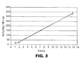
本実施例は、分散体中のSnO2の重量%に対する炭素繊維基板上のSnO2の最終装填量の関係を明らかにする。脱イオン水を添加して、以下の濃度の分散体のサンプルを作製した。0.5、1.0、1.5、1.9、2.0、2.5、3.6、7.2、および15重量%。
【0030】
東レカーボンペーパー060のサンプルを上記のように処理した後、直径5.10cmの円に型抜きし、計量した。図3および4は、処理分散体中のSnO2の重量%の関数として、SnO2装填量の関係を明示するグラフであり、そのグラフは、0.5〜2.5重量%のSnO2と2.5〜15 重量%のSnO2の範囲における分散体に対してほぼ直線である。
【0031】
実施例4
スペクトラカーブのサンプルを以下の濃度のSnO2分散体(2.0、4.0、8.0、および15重量%のSnO2)で、上記のように処理した。脱イオン水およびファイブロ・ダット(Fibro Dat)接触角測定装置(ファイブロ・ダットモデル1100、ファイブロ・システムズ(Fibro Systems)AB、ヘーガーステイン(Hagersten)、スウェーデン)を用いて、各サンプルの水吸収率を測定した。以下の比較サンプル(未処理のスペクトラカーブ、未処理の東レカーボンペーパー060)も測定し、また高密度のアセタートも比較例として測定した。
【0032】
図5は、結果データを明示する。スペクトラカーブカーボンペーパーの水吸収率は、本発明に従って処理した後に、3〜4桁速くなる。
【0033】
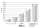
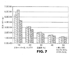
実施例5
東レカーボンペーパー060のシートを上記のように、2.5および15重量%のSnO2分散体で処理した。2.5および15重量%のSnO2で処理した東レとさらに未処理の東レカーボンペーパー060から直径20.3cmのサンプルを取り出した。任意の圧力で、圧縮率および電気抵抗率が同時に測定できるように、2つの絶縁板間のサンプルを圧縮するために備え付けられたプレスを含む抵抗/圧縮試験機を用いて、各サンプルを試験した。図6は、圧力データに対する圧縮率を明示する。図7は、圧力データに対する電気抵抗率を明示する。本発明に係る処理は、炭素繊維の物理特性を著しく損なうことはなかった。
【0034】
本発明の様々な修正形態および変更形態は、本発明の範囲および目的を逸脱することなく、当業者には明らかになるだろう。また本発明は、本明細書で上述した例証となる実施形態を過度に制限するものではないことを理解すべきである。
【図面の簡単な説明】
【0035】
【図1】本発明に従ってSnO2で処理した東レカーボンペーパー060のサンプルの、500倍に拡大した電子顕微鏡写真である。
【図2】未処理の東レカーボンペーパー060の比較サンプルの、500倍に拡大した電子顕微鏡写真である。
【図3】処理分散体中のSnO2の重量%の関数として、本発明に従って処理した炭素繊維基板に対するSnO2装填量のグラフである。
【図4】処理分散体中のSnO2の重量%の関数として、本発明に従って処理した炭素繊維基板に対するSnO2装填量のグラフである。
【図5】本発明に従って処理した炭素繊維基板と対照制御基板に対する水の測定吸収率を示すグラフである。
【図6】本発明に従って処理した炭素繊維基板と対照制御基板の、圧力に対する圧縮率のグラフである。
【図7】本発明に従って処理した炭素繊維基板と対照制御基板の、圧力に対する電気抵抗率のグラフである。【Technical field】
[0001]
In the present invention, a carbon fiber structure is immersed in an aqueous dispersion of metal oxide containing i) 1 to 15% by weight of metal oxide and ii) 0.01% to 5% by weight of a dispersant. Then, it is related with the method of manufacturing a hydrophilic carbon fiber structure by heating a carbon fiber structure and removing a dispersing agent.
[Background]
[0002]
US Pat. No. 5,840,414 discloses a carbon plate for a fuel cell system incorporating a metal oxide to impart hydrophilicity. The document lists possible methods in
[0003]
U.S. Pat. No. 5,998,058 describes a polymer electrolyte membrane fuel cell electrode made of a carbon fiber substrate processed to have both "hydrophilic" and "hydrophobic" pores. A diffusion layer is disclosed. The document describes a method of making the pores more hydrophilic by dipping in a solution of tin tetrachloride-pentahydrate followed by dipping in ammonia.
[0004]
U.S. Patent No. 6,024,848 discloses a porous support plate for an electrochemical cell that includes a contact bilayer adjacent to an electrode that includes a hydrophobic phase and a hydrophilic phase. The document discloses a hydrophilic phase consisting of a mixture of carbon black and a proton exchange resin.
DISCLOSURE OF THE INVENTION
[Means for Solving the Problems]
[0005]
Briefly, the present invention provides an aqueous dispersion of one or more metal oxides comprising a) i) 1-15% by weight metal oxide and ii) 0.01% -5% by weight dispersant. Manufacturing a hydrophilic carbon fiber structure comprising the steps of immersing the carbon fiber structure in the body, and b) subsequently heating the carbon fiber structure sufficiently to remove almost all the dispersant. Provide a way to do it. The aqueous dispersion is usually 1 to 5 wt% metal oxide, more typically 1 to 3 wt% metal oxide, and more typically 1.5 to 2.5 wt% metal oxide. Contains products.
[0006]
Usually, the metal oxide, Sn, Si, Zr, oxides of Ti, Al, and Ce, most typically, is selected from SnO 2. Typically, the dispersant is a non-ionic dispersant such as an alcohol alkoxylate (eg, Triton ™ X100). Typically, the dipping process can be completed in less than 30 minutes, more typically less than 10 minutes, and more typically less than 1 minute. Usually, the entire process can be completed in less than 30 minutes, more typically less than 20 minutes, and most typically less than 5 minutes.
[0007]
In another aspect, the present invention provides a hydrophilic carbon fiber structure produced according to the method of the present invention and having a loading of metal oxide, typically corresponding to 20-50 mg metal per gram carbon.
[0008]
What has not yet been described in the art, and provided by the present invention is a simple and rapid method of producing hydrophilic carbon fiber structures impregnated with a uniform coating of metal oxide.
[0009]
In the present specification, the terms “surfactant” and “dispersant” may be used interchangeably.
[0010]
It is an advantage of the present invention to provide a simple and rapid method of producing a hydrophilic carbon fiber structure impregnated with a uniform coating of metal oxide, usually in about 15 minutes, which is an electrolytic cell. It is useful as an electrode diffusion layer or gas diffusion layer (for example, a fuel cell). It is an advantage of the present invention that no vacuum source is required to wet the processing substrate. It is an advantage of the present invention that only a single immersion bath is required. It is an advantage of the present invention that there is no need to monitor or add chemicals during processing. It is an advantage of the present invention that the use of toxic and corrosive chemicals, such as tin tetrachloride-pentahydrate, used in some prior art processes can be avoided.
BEST MODE FOR CARRYING OUT THE INVENTION
[0011]
The present invention relates to carbon in one or more aqueous dispersions of metal oxides comprising a) i) 1 to 15% by weight of metal oxide and ii) 0.01% to 5% by weight of a dispersant. Provided is a method for producing a hydrophilic carbon fiber structure comprising the steps of dipping the fiber structure, and b) subsequently heating the carbon fiber structure sufficiently to remove substantially all of the dispersant.
[0012]
Usually, the metal oxide is selected from the oxides of Sn, Si, Zr, Ti, Al, and Ce. The most typical metal oxide is SnO 2. Typically, the above aqueous dispersion is 1-5 wt% metal oxide, more typically 1-3 wt% metal oxide, and even more typically 1.5-2.5 wt%. Contains metal oxides. Example 3 described below shows that the correlation of metal loading in the hydrophilic carbon fiber structure to the weight percent of metal oxide in the treated dispersion is 0.5 to 2.5 weight percent metal oxide. And about a linear function for dispersions in the range of 2.5 to 15 weight percent metal oxide. Usually, the hydrophilic carbon fiber structure according to the present invention has a loading of metal oxide equivalent to 20-50 mg of metal per gram of carbon. Specifically, when the metal oxide is SnO 2 , the hydrophilic carbon fiber structure according to the present invention usually has a loading of SnO 2 corresponding to 20 to 50 mg of Sn per gram of carbon. The particle size of the metal oxide is usually less than 1000 nm, more typically 100 nm, more typically 40 nm, and most typically less than 20 nm.
[0013]
Any suitable dispersing agent that can be removed may be used in the heating step. Advantageously, the dispersant may not adversely affect the activity of the fuel cell catalyst (eg, platinum catalyst, etc.). Nonionic, anionic, cationic, and amphoteric suitable dispersants may be used. Usually, the dispersant is nonionic or contains substantially only nonmetallic counter ions (eg, ammonium ions). Most typically, the dispersant is non-ionic. Nonionic dispersants that may be useful in the practice of the present invention include alcohol alkoxylates (eg, Triton ™ X100, Tomadyne ™ 101LF, Iconol ™ TDA6, Aikanol ™). TDA9, Triton ™ DF-12, etc.), amine alkoxylates (eg, Varonic ™ K-205, etc.), alkyl glucosides (eg, Glucpon ™ 425, etc.), alkanolamides, Amine oxides (eg, Tomah Products “AO-14-2” (dihydroxyethylisodecyloxypropylamine oxide), Ninox ™ M (myristylamine oxide), and Valonic ™ ) K-205 (cocoamine ethoxylate) and the like).
[0014]
The salts of quaternary amines useful as the surfactant of the present invention are represented by the following general formula (I)
[Chemical 1]
In the formula, R 1 and R 2 are the same or different and are selected from the group consisting of an alkyl group and a substituted alkyl group, and R 3 is a linear alkyl group, a branched alkyl group, a straight chain alkyl group having about 10 to 20 carbon atoms. Selected from the group consisting of chain heteroalkyl and branched chain heteroalkyl, R 4 is an alkyl group having 1 to about 5 carbon atoms (preferably methyl), and X is a halogen atom, preferably a chlorine atom. Examples of quaternary amine salts include "Q-17-5" (isotridecyloxypropyl poly (5) oxyethylene methyl ammonium chloride, and "QS-80" (quaternary monosoya ammonium chloride). (Mono soya ammonium chloride quarter)), both of which are available from Tomah Products Inc. (Milton WI.), Milton, Wisconsin.
[0015]
Amphoteric surfactants include alkylamidopropyl dimethylbetaines (eg, Tego Betaine ™ L7 Goldschmidt, etc.), alkylamidobetaines (eg, Incronam ™™ 30 (Croda). ), Etc.), imidazoline derivatives (eg, Chimexane ™ HD (Chimex), etc.), N-allyl-beta-iminodipropionic acid (eg, Monateric ™ ISA35 (mona ( Mona) etc.).
[0016]
Most typically, the dispersant is a non-ionic dispersant, the most typical example being an alcohol alkoxylate.
[0017]
Typically, the treatment dispersion is 0.01% to 5% by weight, more typically 0.01% to 1% by weight, and most typically 0.01% to 0.1% by weight nonionic dispersion. Contains agents.
[0018]
Any suitable carbon fiber structure may be used. Usually, the carbon fiber structure is selected from the group consisting of a woven carbon fiber structure and a non-woven carbon fiber structure. Carbon fiber structures that may be useful in the practice of the present invention include Toray (TM) Carbon Paper, SpectraCarb (TM) Carbon Paper, AFN (TM) Nonwoven Carbon. Cloth, Zoltek ™ carbon cloth and the like may be included.
[0019]
Typically, the dipping process is completed in less than 30 minutes, more typically less than 10 minutes, and more typically less than 1 minute. Usually, the entire process is completed in less than 30 minutes, more typically less than 20 minutes, and most typically less than 15 minutes. In an automated continuous process, less than 5 minutes is normal and can be achieved in less than 2 minutes.
[0020]
Furthermore, this invention provides the hydrophilic carbon fiber structure manufactured according to the method of this invention. The hydrophilic carbon fiber structure produced according to the method of the present invention has a high degree of uniformity in metal oxide distribution, as illustrated by a comparison of FIGS. Usually, the hydrophilic carbon fiber structure produced in accordance with the present invention has a metal oxide loading equivalent to 20-50 mg metal per gram carbon. Specifically, the metal oxide is SnO 2 and the hydrophilic carbon fiber structure produced in accordance with the present invention typically has a loading of SnO 2 corresponding to 20-50 mg of Sn per gram of carbon. Have.
[0021]
The present invention is useful in providing a hydrophilic carbon fiber structure useful as an electrode diffusion layer or a gas diffusion layer in an electrolytic cell (eg, a fuel cell).
[0022]
Objects and advantages of the present invention are further illustrated by the following examples, but the specific materials and amounts listed therein, as well as other states and details, are to be construed to unduly limit the present invention. Should not.
【Example】
[0023]
Unless otherwise noted, all reagents were obtained from Aldrich Chemical Co. (Milwaukee, Wis.), Milwaukee, Wis., Or may be obtained or synthesized by well known methods. .
[0024]
Treatment Methods All SnO 2 dispersions used Nyacol® SN15CG SnO 2 dispersion (Nyacol Nano Technologies, Ashland Massachusetts, Ashland MA). the dispersion in the. remained resulting state, pH of. the dispersion containing SnO 2 of 15 wt% is 10.0, SnO 2 particle size is 10 to 15 nm. de Ionic water was added to make dispersions with low SnO 2 content After dilution, a small amount of nonionic surfactant was added to each SnO 2 dispersion, which is a Triton ™ X100 (Union Carbide Corp., Danbury, CT) (Danbury, CT) It is.
[0025]
Porous carbon fiber substrates were selected from Toray ™ carbon paper 060 (Toray Industries, Inc., Tokyo, Japan) and Spectra Curve ™ carbon paper (Spectra Corp., Lawrence, Massachusetts). A sample of the porous carbon fiber substrate was immersed in a SnO 2 / surfactant dispersion for 5 seconds, suspended and dried.
[0026]
Thereafter, the substrate was heated to 380 ° C. for 10 minutes to heat-treat the carbon fiber substrate, and the surfactant was removed.
[0027]
Example 1
Two types of dispersions (2.5 wt% SnO 2 and 15.0 wt% SnO 2 ) were used to treat a sample of
[0028]
Example 2
A 2.15 wt% SnO 2 dispersion was used to treat a sample of
FIG. 1 is an electron micrograph magnified 500 times for a sample treated with 2.15 wt% SnO 2 , and FIG. 2 is an electron micrograph magnified 500 times for an untreated sample.
[0029]
Example 3
This example demonstrates the relationship of the final loading of SnO 2 on the carbon fiber substrate to the weight percent of SnO 2 in the dispersion. Deionized water was added to make dispersion samples with the following concentrations. 0.5, 1.0, 1.5, 1.9, 2.0, 2.5, 3.6, 7.2, and 15 wt%.
[0030]
A sample of
[0031]
Example 4
Spectra curve samples were treated as described above with the following concentrations of SnO 2 dispersion (2.0, 4.0, 8.0, and 15 wt% SnO 2 ). Water absorption of each sample using deionized water and Fibro Dat contact angle measuring device (Fibro Dat model 1100, Fibro Systems AB, Hagersten, Sweden) Was measured. The following comparative samples (untreated Spectra curve, untreated Toray carbon paper 060) were also measured, and high-density acetate was also measured as a comparative example.
[0032]
FIG. 5 demonstrates the result data. The water absorption rate of Spectra curve carbon paper increases 3 to 4 orders of magnitude after treatment according to the present invention.
[0033]
Example 5
Sheets of
[0034]
Various modifications and alterations of this invention will become apparent to those skilled in the art without departing from the scope and purpose of this invention. It should also be understood that the invention is not intended to unduly limit the illustrative embodiments described hereinabove.
[Brief description of the drawings]
[0035]
1 is an electron micrograph magnified 500 times of a sample of
FIG. 2 is an electron micrograph of a comparative sample of untreated
FIG. 3 is a graph of SnO 2 loading on a carbon fiber substrate treated according to the present invention as a function of weight percent of SnO 2 in the treated dispersion.
FIG. 4 is a graph of SnO 2 loading on a carbon fiber substrate treated according to the present invention as a function of the weight percentage of SnO 2 in the treated dispersion.
FIG. 5 is a graph showing measured water absorption for a carbon fiber substrate treated according to the present invention and a control control substrate.
FIG. 6 is a graph of compressibility versus pressure for a carbon fiber substrate treated according to the present invention and a control control substrate.
FIG. 7 is a graph of electrical resistivity versus pressure for a carbon fiber substrate treated according to the present invention and a control control substrate.
Claims (25)
ii)0.01%〜5重量%の分散剤と
を含む、1種以上の金属酸化物の水性分散体中に炭素繊維構造体を浸漬する工程、および
b)続いて、炭素繊維構造体を十分に加熱して前記分散剤のほぼ全てを除去する工程
を含む親水性の炭素繊維構造体を製造する方法。a) i) 1 to 15% by weight of metal oxide;
ii) immersing the carbon fiber structure in an aqueous dispersion of one or more metal oxides comprising 0.01% to 5% by weight of a dispersant; and b) subsequently, A method for producing a hydrophilic carbon fiber structure comprising a step of sufficiently heating to remove almost all of the dispersant.
Applications Claiming Priority (2)
| Application Number | Priority Date | Filing Date | Title |
|---|---|---|---|
| US09/999,561 US6733841B2 (en) | 2001-11-01 | 2001-11-01 | Hydrophilic treatment of a carbon fiber construction |
| PCT/US2002/027366 WO2003038180A1 (en) | 2001-11-01 | 2002-08-27 | Hydrophilic treatment of a carbon fiber construction |
Publications (2)
| Publication Number | Publication Date |
|---|---|
| JP2005507980A true JP2005507980A (en) | 2005-03-24 |
| JP2005507980A5 JP2005507980A5 (en) | 2006-01-05 |
Family
ID=25546474
Family Applications (1)
| Application Number | Title | Priority Date | Filing Date |
|---|---|---|---|
| JP2003540435A Pending JP2005507980A (en) | 2001-11-01 | 2002-08-27 | Hydrophilic treatment of carbon fiber structure |
Country Status (6)
| Country | Link |
|---|---|
| US (1) | US6733841B2 (en) |
| EP (1) | EP1440202A1 (en) |
| JP (1) | JP2005507980A (en) |
| KR (1) | KR20040053240A (en) |
| CA (1) | CA2463651A1 (en) |
| WO (1) | WO2003038180A1 (en) |
Cited By (1)
| Publication number | Priority date | Publication date | Assignee | Title |
|---|---|---|---|---|
| US11437629B2 (en) | 2018-02-15 | 2022-09-06 | Mitsubishi Chemical Corporation | Hydrophilic porous carbon electrode and manufacturing method of same |
Families Citing this family (9)
| Publication number | Priority date | Publication date | Assignee | Title |
|---|---|---|---|---|
| US7160424B2 (en) * | 2001-11-28 | 2007-01-09 | 3M Innovative Properties Company | Electrophoretically deposited hydrophilic coatings for fuel cell diffuser/current collector |
| JP2004031325A (en) * | 2002-05-10 | 2004-01-29 | Mitsubishi Electric Corp | Solid polymer fuel cell and method of manufacturing same |
| US20060286436A1 (en) * | 2005-06-21 | 2006-12-21 | Amir Faghri | Planar fuel cell stack and method of fabrication of the same |
| US8685580B2 (en) * | 2008-06-20 | 2014-04-01 | GM Global Technology Operations LLC | Fuel cell with an electrolyte stabilizing agent and process of making the same |
| JP5683458B2 (en) * | 2008-06-20 | 2015-03-11 | エスゲーエル カーボン ソシエタス ヨーロピアSGL Carbon SE | Gas diffusion layer |
| US8177884B2 (en) | 2009-05-20 | 2012-05-15 | United Technologies Corporation | Fuel deoxygenator with porous support plate |
| DE102016210729A1 (en) | 2016-06-16 | 2017-12-21 | Bayerische Motoren Werke Aktiengesellschaft | Battery component and galvanic element with porous carbon fiber layer |
| CN109768238B (en) * | 2018-12-24 | 2021-01-15 | 肇庆市华师大光电产业研究院 | Sb-C/S nanofiber composite material, preparation method and application |
| CN111116930B (en) * | 2019-12-31 | 2021-11-16 | 中山大学 | Hyper-dispersant, thermoplastic resin-based carbon fiber composite material and preparation method thereof |
Family Cites Families (5)
| Publication number | Priority date | Publication date | Assignee | Title |
|---|---|---|---|---|
| GB9106806D0 (en) * | 1991-04-02 | 1991-05-22 | T & N Technology Ltd | Non-asbestos flexible sheet material |
| IT1271563B (en) | 1993-06-04 | 1997-05-30 | Siad | POROUS MONOLITHIC MASS FOR GAS CONTAINERS |
| US5840414A (en) | 1996-11-15 | 1998-11-24 | International Fuel Cells, Inc. | Porous carbon body with increased wettability by water |
| US6024848A (en) | 1998-04-15 | 2000-02-15 | International Fuel Cells, Corporation | Electrochemical cell with a porous support plate |
| US5998058A (en) | 1998-04-29 | 1999-12-07 | International Fuel Cells Corporation | Porous support layer for an electrochemical cell |
-
2001
- 2001-11-01 US US09/999,561 patent/US6733841B2/en not_active Expired - Fee Related
-
2002
- 2002-08-27 CA CA002463651A patent/CA2463651A1/en not_active Abandoned
- 2002-08-27 KR KR10-2004-7006524A patent/KR20040053240A/en not_active Application Discontinuation
- 2002-08-27 EP EP02759476A patent/EP1440202A1/en not_active Withdrawn
- 2002-08-27 WO PCT/US2002/027366 patent/WO2003038180A1/en active Application Filing
- 2002-08-27 JP JP2003540435A patent/JP2005507980A/en active Pending
Cited By (2)
| Publication number | Priority date | Publication date | Assignee | Title |
|---|---|---|---|---|
| US11437629B2 (en) | 2018-02-15 | 2022-09-06 | Mitsubishi Chemical Corporation | Hydrophilic porous carbon electrode and manufacturing method of same |
| US11777109B2 (en) | 2018-02-15 | 2023-10-03 | Mitsubishi Chemical Corporation | Hydrophilic porous carbon electrode and manufacturing method of same |
Also Published As
| Publication number | Publication date |
|---|---|
| US20030082374A1 (en) | 2003-05-01 |
| WO2003038180A1 (en) | 2003-05-08 |
| US6733841B2 (en) | 2004-05-11 |
| EP1440202A1 (en) | 2004-07-28 |
| KR20040053240A (en) | 2004-06-23 |
| CA2463651A1 (en) | 2003-05-08 |
Similar Documents
| Publication | Publication Date | Title |
|---|---|---|
| US9997788B2 (en) | Methods of producing porous platinum-based catalysts for oxygen reduction | |
| KR100841204B1 (en) | Fuel Cells and Other Products Containing Modified Carbon Products | |
| Ju et al. | Pd nanoparticles deposited on nitrogen-doped HOPG: new insights into the Pd-catalyzed oxygen reduction reaction | |
| JP2005507980A (en) | Hydrophilic treatment of carbon fiber structure | |
| JP3845823B2 (en) | Method for coating natural fibers with carbon nanotubes | |
| US7557057B2 (en) | Method for preparation of highly dispersed supported platinum catalyst | |
| Chen et al. | ZIF‐Mg (OH) 2 Dual Template Assisted Self‐Confinement of Small PtCo NPs as Promising Oxygen Reduction Reaction in PEM Fuel Cell | |
| Mohammadi et al. | Characterization of PbO2 coating electrodeposited onto stainless steel 316L substrate for using as PEMFC's bipolar plates | |
| Nouralishahi et al. | Characteristics and performance of urea modified Pt-MWCNTs for electro-oxidation of methanol | |
| WO2003046259A1 (en) | Electrophoretically deposited hydrophilic coatings for fuel cell diffuser/current collector | |
| CN109126793B (en) | Electrochemical preparation method of monoatomic copper electrocatalyst | |
| Devivaraprasad et al. | Solvent-dependent adsorption of perfluorosulfonated ionomers on a Pt (111) surface using atomic force microscopy | |
| JP6665714B2 (en) | Polymer electrolyte fuel cell | |
| WO2021198974A1 (en) | Carbon electrodes having improved electrocatalytic activity | |
| RU2324538C1 (en) | Catalyst with nanoparticles on carrier and method of its production | |
| Ogasawara et al. | Nanocarbon-induced etching property of semiconductor surfaces: testing nanocarbon’s catalytic activity for oxygen reduction reaction at a single-sheet level | |
| JPS62163261A (en) | Manufacture of electrode of high electric conductivity | |
| CN106757142B (en) | Preparation method and application of carbon fiber loaded nanoscale bimetal PtCo catalytic electrode | |
| Qi et al. | Effects of ethylene glycol and caprolactam on the ORR and HOR performances of Pt/C catalysts | |
| CN112062227A (en) | Method for reducing scaling on cathode surface | |
| JP2006346571A (en) | Method for manufacturing platinum catalyst for fuel cell | |
| CN105148749A (en) | Diffusion dialysis membrane and preparation method thereof | |
| JP6800156B2 (en) | Fuel cell gas diffusion layer made of carbon substrate grafted with aromatic groups | |
| JP3409081B2 (en) | Method for producing ion-exchange membrane-electrode assembly | |
| WO2023286560A1 (en) | Cathode diffusion layer for production of organic hydride |
Legal Events
| Date | Code | Title | Description |
|---|---|---|---|
| A521 | Written amendment |
Free format text: JAPANESE INTERMEDIATE CODE: A523 Effective date: 20050628 |
|
| A621 | Written request for application examination |
Free format text: JAPANESE INTERMEDIATE CODE: A621 Effective date: 20050628 |
|
| A977 | Report on retrieval |
Free format text: JAPANESE INTERMEDIATE CODE: A971007 Effective date: 20070927 |
|
| A131 | Notification of reasons for refusal |
Free format text: JAPANESE INTERMEDIATE CODE: A131 Effective date: 20071016 |
|
| A02 | Decision of refusal |
Free format text: JAPANESE INTERMEDIATE CODE: A02 Effective date: 20080311 |