JP2005505118A - System and method for charging a battery - Google Patents
System and method for charging a battery Download PDFInfo
- Publication number
- JP2005505118A JP2005505118A JP2003533412A JP2003533412A JP2005505118A JP 2005505118 A JP2005505118 A JP 2005505118A JP 2003533412 A JP2003533412 A JP 2003533412A JP 2003533412 A JP2003533412 A JP 2003533412A JP 2005505118 A JP2005505118 A JP 2005505118A
- Authority
- JP
- Japan
- Prior art keywords
- battery
- charging
- charge
- amount
- voltage
- Prior art date
- Legal status (The legal status is an assumption and is not a legal conclusion. Google has not performed a legal analysis and makes no representation as to the accuracy of the status listed.)
- Pending
Links
- 238000000034 method Methods 0.000 title claims abstract description 163
- 230000008569 process Effects 0.000 claims abstract description 128
- 239000002253 acid Substances 0.000 claims abstract description 69
- 230000008859 change Effects 0.000 claims description 16
- 238000012544 monitoring process Methods 0.000 claims description 10
- 238000005259 measurement Methods 0.000 claims description 8
- 230000001133 acceleration Effects 0.000 claims description 2
- 230000000153 supplemental effect Effects 0.000 claims description 2
- 230000007812 deficiency Effects 0.000 claims 1
- 238000011156 evaluation Methods 0.000 abstract description 4
- 239000003792 electrolyte Substances 0.000 description 35
- 238000010586 diagram Methods 0.000 description 16
- 238000004458 analytical method Methods 0.000 description 10
- 230000004044 response Effects 0.000 description 10
- 238000013019 agitation Methods 0.000 description 9
- 239000007789 gas Substances 0.000 description 8
- 239000011149 active material Substances 0.000 description 7
- 230000001276 controlling effect Effects 0.000 description 7
- 230000006870 function Effects 0.000 description 7
- 230000005484 gravity Effects 0.000 description 7
- 238000013459 approach Methods 0.000 description 6
- 230000007423 decrease Effects 0.000 description 6
- 238000001514 detection method Methods 0.000 description 6
- QAOWNCQODCNURD-UHFFFAOYSA-N Sulfuric acid Chemical compound OS(O)(=O)=O QAOWNCQODCNURD-UHFFFAOYSA-N 0.000 description 5
- 230000008901 benefit Effects 0.000 description 5
- OJIJEKBXJYRIBZ-UHFFFAOYSA-N cadmium nickel Chemical compound [Ni].[Cd] OJIJEKBXJYRIBZ-UHFFFAOYSA-N 0.000 description 4
- 238000004364 calculation method Methods 0.000 description 4
- 230000003750 conditioning effect Effects 0.000 description 4
- 238000013461 design Methods 0.000 description 4
- 230000000694 effects Effects 0.000 description 4
- 238000012545 processing Methods 0.000 description 4
- 239000004020 conductor Substances 0.000 description 3
- 238000005516 engineering process Methods 0.000 description 3
- 239000007788 liquid Substances 0.000 description 3
- 239000011244 liquid electrolyte Substances 0.000 description 3
- 238000010943 off-gassing Methods 0.000 description 3
- 230000008929 regeneration Effects 0.000 description 3
- 238000011069 regeneration method Methods 0.000 description 3
- 238000003756 stirring Methods 0.000 description 3
- 230000005518 electrochemistry Effects 0.000 description 2
- 239000007772 electrode material Substances 0.000 description 2
- 239000000463 material Substances 0.000 description 2
- 239000011159 matrix material Substances 0.000 description 2
- -1 nickel metal hydride Chemical class 0.000 description 2
- 238000004886 process control Methods 0.000 description 2
- 230000001172 regenerating effect Effects 0.000 description 2
- 239000004576 sand Substances 0.000 description 2
- 238000013517 stratification Methods 0.000 description 2
- 230000007704 transition Effects 0.000 description 2
- MYMOFIZGZYHOMD-UHFFFAOYSA-N Dioxygen Chemical compound O=O MYMOFIZGZYHOMD-UHFFFAOYSA-N 0.000 description 1
- UFHFLCQGNIYNRP-UHFFFAOYSA-N Hydrogen Chemical compound [H][H] UFHFLCQGNIYNRP-UHFFFAOYSA-N 0.000 description 1
- WHXSMMKQMYFTQS-UHFFFAOYSA-N Lithium Chemical compound [Li] WHXSMMKQMYFTQS-UHFFFAOYSA-N 0.000 description 1
- 206010037660 Pyrexia Diseases 0.000 description 1
- 230000009286 beneficial effect Effects 0.000 description 1
- NSAODVHAXBZWGW-UHFFFAOYSA-N cadmium silver Chemical compound [Ag].[Cd] NSAODVHAXBZWGW-UHFFFAOYSA-N 0.000 description 1
- 239000003990 capacitor Substances 0.000 description 1
- 238000001311 chemical methods and process Methods 0.000 description 1
- 230000001143 conditioned effect Effects 0.000 description 1
- 238000000354 decomposition reaction Methods 0.000 description 1
- 229910001882 dioxygen Inorganic materials 0.000 description 1
- 238000005868 electrolysis reaction Methods 0.000 description 1
- 230000005294 ferromagnetic effect Effects 0.000 description 1
- 239000001257 hydrogen Substances 0.000 description 1
- 229910052739 hydrogen Inorganic materials 0.000 description 1
- 238000005342 ion exchange Methods 0.000 description 1
- 150000002500 ions Chemical class 0.000 description 1
- UGKDIUIOSMUOAW-UHFFFAOYSA-N iron nickel Chemical compound [Fe].[Ni] UGKDIUIOSMUOAW-UHFFFAOYSA-N 0.000 description 1
- 229910052744 lithium Inorganic materials 0.000 description 1
- 238000011068 loading method Methods 0.000 description 1
- 238000004519 manufacturing process Methods 0.000 description 1
- 229910052987 metal hydride Inorganic materials 0.000 description 1
- 238000012986 modification Methods 0.000 description 1
- 230000004048 modification Effects 0.000 description 1
- 229910052759 nickel Inorganic materials 0.000 description 1
- PXHVJJICTQNCMI-UHFFFAOYSA-N nickel Substances [Ni] PXHVJJICTQNCMI-UHFFFAOYSA-N 0.000 description 1
- QELJHCBNGDEXLD-UHFFFAOYSA-N nickel zinc Chemical compound [Ni].[Zn] QELJHCBNGDEXLD-UHFFFAOYSA-N 0.000 description 1
- 125000004430 oxygen atom Chemical group O* 0.000 description 1
- 238000010248 power generation Methods 0.000 description 1
- 238000011084 recovery Methods 0.000 description 1
- 230000001105 regulatory effect Effects 0.000 description 1
- 230000003716 rejuvenation Effects 0.000 description 1
- 230000008439 repair process Effects 0.000 description 1
- 230000000630 rising effect Effects 0.000 description 1
- 238000005070 sampling Methods 0.000 description 1
- XLYOFNOQVPJJNP-UHFFFAOYSA-N water Substances O XLYOFNOQVPJJNP-UHFFFAOYSA-N 0.000 description 1
Images


Classifications
-
- H—ELECTRICITY
- H02—GENERATION; CONVERSION OR DISTRIBUTION OF ELECTRIC POWER
- H02J—CIRCUIT ARRANGEMENTS OR SYSTEMS FOR SUPPLYING OR DISTRIBUTING ELECTRIC POWER; SYSTEMS FOR STORING ELECTRIC ENERGY
- H02J7/00—Circuit arrangements for charging or depolarising batteries or for supplying loads from batteries
- H02J7/02—Circuit arrangements for charging or depolarising batteries or for supplying loads from batteries for charging batteries from ac mains by converters
- H02J7/04—Regulation of charging current or voltage
-
- H—ELECTRICITY
- H01—ELECTRIC ELEMENTS
- H01M—PROCESSES OR MEANS, e.g. BATTERIES, FOR THE DIRECT CONVERSION OF CHEMICAL ENERGY INTO ELECTRICAL ENERGY
- H01M10/00—Secondary cells; Manufacture thereof
- H01M10/42—Methods or arrangements for servicing or maintenance of secondary cells or secondary half-cells
- H01M10/44—Methods for charging or discharging
-
- H—ELECTRICITY
- H02—GENERATION; CONVERSION OR DISTRIBUTION OF ELECTRIC POWER
- H02J—CIRCUIT ARRANGEMENTS OR SYSTEMS FOR SUPPLYING OR DISTRIBUTING ELECTRIC POWER; SYSTEMS FOR STORING ELECTRIC ENERGY
- H02J7/00—Circuit arrangements for charging or depolarising batteries or for supplying loads from batteries
- H02J7/007—Regulation of charging or discharging current or voltage
- H02J7/00712—Regulation of charging or discharging current or voltage the cycle being controlled or terminated in response to electric parameters
- H02J7/007182—Regulation of charging or discharging current or voltage the cycle being controlled or terminated in response to electric parameters in response to battery voltage
- H02J7/007184—Regulation of charging or discharging current or voltage the cycle being controlled or terminated in response to electric parameters in response to battery voltage in response to battery voltage gradient
-
- H—ELECTRICITY
- H01—ELECTRIC ELEMENTS
- H01M—PROCESSES OR MEANS, e.g. BATTERIES, FOR THE DIRECT CONVERSION OF CHEMICAL ENERGY INTO ELECTRICAL ENERGY
- H01M10/00—Secondary cells; Manufacture thereof
- H01M10/06—Lead-acid accumulators
-
- H—ELECTRICITY
- H01—ELECTRIC ELEMENTS
- H01M—PROCESSES OR MEANS, e.g. BATTERIES, FOR THE DIRECT CONVERSION OF CHEMICAL ENERGY INTO ELECTRICAL ENERGY
- H01M10/00—Secondary cells; Manufacture thereof
- H01M10/42—Methods or arrangements for servicing or maintenance of secondary cells or secondary half-cells
- H01M10/44—Methods for charging or discharging
- H01M10/446—Initial charging measures
-
- Y—GENERAL TAGGING OF NEW TECHNOLOGICAL DEVELOPMENTS; GENERAL TAGGING OF CROSS-SECTIONAL TECHNOLOGIES SPANNING OVER SEVERAL SECTIONS OF THE IPC; TECHNICAL SUBJECTS COVERED BY FORMER USPC CROSS-REFERENCE ART COLLECTIONS [XRACs] AND DIGESTS
- Y02—TECHNOLOGIES OR APPLICATIONS FOR MITIGATION OR ADAPTATION AGAINST CLIMATE CHANGE
- Y02E—REDUCTION OF GREENHOUSE GAS [GHG] EMISSIONS, RELATED TO ENERGY GENERATION, TRANSMISSION OR DISTRIBUTION
- Y02E60/00—Enabling technologies; Technologies with a potential or indirect contribution to GHG emissions mitigation
- Y02E60/10—Energy storage using batteries
Abstract
鉛蓄電池の寿命を有利に延長するように鉛蓄電池を充電する方法が説明される。充電プロセスの終了が、印加される充電電圧の第1の導関数(dv/dt)と第2の導関数(d2v/dt2)との評価に基づいている。充電基準として第1の導関数(dv/dt)と第2の導関数(d2v/dt2)とを使用することによって、電池から以前に取り除かれたアンペア時の正確な量を計算に入れる過充電の量が電池に印加される。本発明の充電プロセスを実行する充電器構成も説明される。A method for charging a lead acid battery to advantageously extend the life of the lead acid battery is described. The end of the charging process is based on the evaluation of the first derivative (dv / dt) and the second derivative (d2v / dt2) of the applied charging voltage. Overcharge to account for the exact amount of ampere hours previously removed from the battery by using the first derivative (dv / dt) and the second derivative (d2v / dt2) as the charging criteria Is applied to the battery. A charger configuration for performing the charging process of the present invention is also described.
Description
【技術分野】
【0001】
本発明は、開放型ディープサイクル鉛蓄電池の再充電プロセスの終了を制御する方法に関する。さらに特に、本発明は、最も最近の先行の電池充電事象の後に放電されたエネルギーの量に直接的に関係付けられている再充電エネルギーの量をこうした電池に供給する手順に関する。本発明は、さらに、こうした手順を具体化する装置にも関する。
【背景技術】
【0002】
ニッケルカドミウム電池、ニッケル水素電池、ニッケル鉄電池、リチウム電池、銀カドミウム電池、および、ディープサイクル鉛蓄電池のような様々な異なる種類の再充電可能な蓄電池が知られている。ディープサイクル鉛蓄電池は、例えば従来の自動車に使用されている電池のようなSLI(始動(starting)、照明(lighting)、点火(ignition))鉛蓄電池とは異なっている。SLI電池は、大幅な充電と再充電との反復サイクルに耐えるように設計も構成もされておらず、したがって本発明の意味では再充電可能な電池ではない。
【0003】
米国特許第4,392,101号および第4,503,378号のような特許から、電池が完全充電状態にあるということ、または、電池が完全充電状態には達していないが完全充電状態に近い比較的予測可能な局面にあるということを示す仕方で電池の再充電中に変化する再充電可能電池の特定の特徴が、電池の種類に係わらずに存在するということが公知である。これらの特許と他の刊行物は、この特徴を監視するための、および、この特徴の特定の事象や条件や状態を検出し、電池充電プロセスを終了させるように、または、事前設定された時間にわたってもしくは事前設定された仕方で充電を継続させるようにこの検出を使用するための装置および方法を説明する。こうした事前設定された仕方は、典型的には、検出された事象の時点で使用されている充電プロセスとは異なる充電プロセスを使用する。こうした充電事象検出方法は変曲分析法(inflection analysis method)として知られているが、これは、この方法が、例えば充電プロセス中の、電池電圧または電池電流の変化を示す時間ベースの曲線における特定の変曲点の検出に基づいているからである。現在までに説明されている変曲分析は、大半の種類の再充電可能電池の再充電を制御する上で有効であるが、上述したような変曲分析は、電池電解質がゲルのような何らかの支持マトリックスの中に拘束されてはいない液体(典型的には硫酸)である開放型ディープサイクル鉛蓄電池の再充電を制御するのには、あまり適切には役立たないということが判明している。
【0004】
開放型ディープサイクル鉛蓄電池は、ゴルフカー、フォークリフトトラック、および、シザーリフト車両のような電動車両のためのエネルギー源として広く使用されている。この鉛蓄電池は、さらに、病院や他の建物と施設とにおける無停電電源の中で使用され、および、光発電電力設備の構成要素として使用されている。上述したような変曲分析法が開放型ディープサイクル鉛蓄電池の再充電を制御するためにはあまり役立たない理由が、一例としての電気ゴルフカーのこうした電池の使用から理解されることが可能である。
【0005】
電気ゴルフカーは、4個または6個等の開放型ディープサイクル鉛蓄電池の組によって給電される。どのゴルフコースにも、ゴルファーによって利用可能なこうしたゴルフカーの集団がある。この集団の中の個々のゴルフカーは、その集団の中の他のゴルフカーよりも古い電池を有することがある。特定のゴルフカーが他のゴルフカーよりも頻繁に使用されることがある。幾台かのゴルフカーが、日によって他のゴルフカーよりも長時間にわたって使用されることがある。幾台かのゴルフカーが、それを使用するゴルファーの状況や走行した地形の違いや他の理由に応じて、日によって他のゴルフカーよりも過酷な使用条件を被ることがある。さらに、ゴルフカー集団中のすべての電池が同一の製造業者からのものであり、かつ、同一の公称上の古さである場合にさえ、電池の性能と寿命に影響を与える可能性があり、および、重要なことであるが再充電プロセスに電池が応答する仕方に影響を与える可能性がある種類の、電池相互間の著しい差異がなお存在するということが知られている。したがって、その集団内のゴルフカーが再充電されることになっている1日の最後には、ゴルフカーごとに電池の放電状態の間に大きな差異がある可能性があり、したがって、電池がどのように充電される必要があるかに関してゴルフカーごとに当然の大きな差異がある可能性がある。集団全体にわたる均等な再充電手続きが、幾つかの電池が不十分にしか再充電されないこと、または、この方がさらに可能性が高いが、電池の大半が著しく過充電されることを引き起こすだろう。こうした電池の著しい過充電は電池寿命を低減させる。一般的に、ゴルフカー集団を再充電するために雇われている人間は、こうした著しい過充電の影響と、過充電が生じている時点を判定する方法とを理解していない。したがって、電気ゴルフカーで使用される電池が、著しい過充電を回避する装置およびプロセスによって再充電され、および、放電状態、古さ、製造上のばらつき等を原因とする電池相互間の差異を本来的に吸収し処理する仕方で再充電されることが望ましい。
【0006】
ディープサイクル鉛蓄電池は、完全充電状態からの多量の放電と、放電状態から完全充電状態への再充電との反復サイクルに耐えるように設計されている。液体電解質を使用しない他種の再充電可能な電池に比較して、開放型ディープサイクル鉛蓄電池の液体酸電解質(liquid acid electrolyte)は、特定の電池、または、互いに組み合わされて繰り返し使用される少数の電池の特定の組が、再充電事象が開始される時点の電池の状態にその度合いが関係付けられている、制御された過充電を実現する仕方で再充電されることを必要とする特別な条件をもたらす。言い換えると、開放型ディープサイクル鉛蓄電池の効果的な再充電は、理想的には、電池の最も最近の先行デューティサイクル(最も最近の先行充電事象以来の使用期間)中に電池から取り除かれた(放電された)エネルギーの量によって決定される、制御された過充電を含まなければならない。この理由は、先行のデューティサイクルとそれに続く再充電事象との最中に液体電解質に生じるものに関係している。
【0007】
鉛蓄電池のセルが放電すると、電解質中の酸イオンがセル電極に移動し、および、酸素原子がセルの活物質から電解質の中に移動し、電解質の水素イオンと共に水を形成する。したがって、電解質の酸が漸進的に希釈され、その比重がより高い開始比重から漸進的に1.0に近づく。セルが再充電される時には、そのイオン交換プロセスが、電解質の酸と活物質との再生を生じさせるために逆転させられる。電解質が、ゲルマトリックス中に存在している場合とは反対に、自由な液体としてセル中に存在している(すなわち、セルが開放型である)ならば、その再生された酸は、希薄な電解質よりも重いので、その生成時にセルの底に沈む。再充電プロセスが進行するにつれて、ますます高濃度になる再生された酸がセルの底に集まる。セルの活物質が完全に再生され終わった時点で、理論的にはセルはクーロンベースで完全に充電されている。しかし、このセルは、電解質の層状化のせいで、蓄積されたエネルギーを供給するために使用することには適した状態ではない。電解質はセル全体にわたって均一な酸性度になく、したがって、再生された酸電解質は、再生された活物質に対してその再生活物質の全面積にわたって均一に有効な接触状態にあるわけではない。セルがこの時点で放電することを求められる場合には、放電の電気化学的プロセスが、主として、電解質の酸が過剰に高濃度になっているセルの下部部分で生じることになる。セルは、所望のレベルでエネルギーを放出することがなく、および、セルの底部内の過剰に濃縮された酸が、隣接した活物質が過剰に早く劣化することを引き起こすことになる。この結果として、電池寿命を著しく短縮させる形でのセルの性能不足が生じる。
【0008】
活物質の完全な再生的回復の直前に生じる鉛蓄電池セルの再充電プロセスの一部分において、再充電プロセスの通常の一部分として気体がセル内で発生する。この気体の気泡が電解質中を通ってセルの最上部に上昇し、このプロセスの中でセル内の電解質の循環(攪拌)を誘発する。しかし、再充電プロセスが活物質の完全な再生の時点で終了させられる場合には、生じている気体発生の量は、電解質を適切に攪拌してセル全体にわたって均一な酸濃度(均一な比重)を電解質にもたらすには不十分だろう。この理由から、開放型ディープサイクル鉛蓄電池の再充電プロセスを完全充電の時点を超えて継続すること、すなわち、再生された電解質の適切な攪拌を得るために一定の時間にわたって気体発生プロセスを延長することが一般的な慣習である。すなわち、セルは意図的に過充電される。
【0009】
現在の慣習は、最大限の攪拌を必要とする1つまたは複数のセルの内の電解質を十分に攪拌するのに適切であるように設定された予め決められた量だけ、幾つかのセルを含むこうした電池を過充電することである。この過充電の予め決められた量の設定は、セルがその先行のデューティサイクル中に最大限に放電され終わっており、かつ、そのセルが古さと条件と温度とに関する特定の属性を有するという仮定に基づいている。しかし、電気ゴルフカー集団の運用の説明において上記で示したように、この仮定は、再充電を必要とする電池の大半に関しては適切ではない。この結果として、開放型ディープサイクル鉛蓄電池の再充電の最終段階において印加される過充電の量に関してこの仮定に依存することは、(大半ではなくとも)相当数のこうした電池が極めて大幅に過充電されることの原因となる。こうした電池の極めて大幅な過充電は、特に数回を超えて反復される場合に、こうした電池の有効寿命を著しく減少させる。
【0010】
上述の説明は、電池の再充電プロセスを制御するための変曲分析方法の従来の説明が、開放型ディープサイクル鉛蓄電池の再充電に適用される場合にどれほど不十分であるかを理解するための基礎を提供する。
【0011】
米国特許第4,392,101号は、再充電可能な電池の再充電の制御における変曲分析の使用の初期の説明である。この特許は、再充電可能な電池が再充電プロセスに大まかに類似している応答特性を一般的に有するということを教示する。この特許は、電池の電圧または電流が例えば再充電中の時間に対比してグラフの形でプロットされる場合に、その結果としての電圧/時間曲線または電流/時間曲線が大まかな類似性を有するだろうということを教示する。充電プロセスの開始後に、電池セルを画定するために使用される個々の材料には無関係に、これらの曲線は、グラフの線がその湾曲を反転させる、すなわち、変曲させられる、少なくとも1対の変曲点を示すだろう。これら変曲点が、印加された充電エネルギーに対する電池の反応の様々な段階を示しすなわち表すということと、各々のセルのタイプに関して、この変曲が、電池が完全充電状態に達する前に、または、完全充電状態に達する時点で、充電プロセス中の比較的に予測可能な時点で生じるということが明らかにされている。変曲点の発生が予測可能であることは、一般的に、電池の実際電圧、個々のセルの特性、個別の充電履歴、または、実際の周囲温度条件といった要因によっては影響されない(これらの要因に無関係に生じる)ということが明らかにされている。この特許は、監視されている電池特性(電圧または電流)の時間に対する第1または第2の導関数の状態または特徴を観察することによって、変曲点が識別可能であるということを明らかにする。さらに明確に述べると、この特許は、第2の導関数のグラフが充電プロセス中に少なくとも2回はゼロ軸を横断し(この導関数の符号が、正から負に、または、これとは逆に変化し)、および、その導関数の第2のゼロ軸横断が、電池が完全充電状態に達する時に生じるか、または、完全充電が得られる直前のわずかな時間期間中に生じるだろうということを教示する。しかし、その特許は、鉛蓄電池の例では、電圧の第2の時間ベースの導関数がどの時点で完全充電に関して生じるかを説明することを試みていない。その特許の主要な説明は、その導関数の第2のゼロ軸横断が検出された時点から予め決められた時間を経過した後に再充電が終了させられるニッケルカドミウム電池に関するものである。ニッケルカドミウム電池は、化学プロセスの一部分として存在している可変濃度の電解質を使用せず、したがって、こうした電池は、過充電処理から何の利益も得ないか、または、過充電処理を全く必要としない。
【0012】
米国特許第4,503,378号が、変曲分析による再充電の制御をニッケル亜鉛電池に適用し、および、このタイプの電池の場合に、再充電が、時間に対する電池電圧の第2の導関数の符号変化(ゼロ軸横断)の第2の事例の発生時に終了させられることになるということを開示する。さらに、この特許は、第2の導関数が正から負にゼロ軸を横断するのと同時に、時間に対する電池電圧の第1の導関数の値が最大値すなわちピーク値にあり、この事実が、第2の導関数のゼロ横断が確認されることを可能にすると述べている。
【0013】
「電圧変曲点を検出することによって15分以内で電池を安全に充電する」という表題の記事がEDM Magazineの1994年9月1日号に掲載された。この記事は主としてニッケルカドミウム電池の高速充電に焦点を当てている。この記事は、変曲分析が鉛蓄電池にも当てはまると注釈している。この関連において、この記事は、「鉛蓄電池では、第2のdV/dt変曲が、電池が完全充電に達する前の予測可能な時間期間において生じるが、電池のアンペア時の容量定格から、完全充電を得るために必要とされる増分充電の持続時間を容易に導き出すことが可能である。」と述べている。この記述は、電池の真の再充電の必要性という点から見て極めて大幅に過充電することなしに、どのようにして開放型ディープサイクル鉛蓄電池を効率的に確実にかつ効果的に充電するかという問題の解決に対しては、少なくとも2つの理由から寄与しない。第1に、鉛蓄電池のAhr(アンペア時)容量定格は、工学的な情報から正確に求めることが可能な精確な値ではない。むしろ、このアンペア時容量定格は、マーケティング上の目標や保証方針等の要因のような製造業者に特有のビジネス上の要因の結果として、製造業者が電池のモデルまたはタイプに割り当てる値である。電池の「アンペア時」容量定格は、その種類またはタイプの平均的な電池の、おそらくは明記されていない条件下における、予想可能な性能に関する製造業者の言明であるにすぎない。この「アンペア時」容量定格は、特定のデューティサイクルの完了後の特定の電池の充電の必要性、すなわち、再充電事象を受ける前の電池の放電の深さに対して、確実な関係を持たない。第2に、この「アンペア時」容量定格は、電池自体以外のソースから得られることが必要とされている値である。必要とされているものは、電池の放電状態を示しており、かつ、再生電解質を適切に攪拌するのに必要な量だけ電池を過充電するために使用可能である、電池自体から導き出された情報を使用して、開放型ディープサイクル鉛蓄電池を充電する方法である。
【0014】
上述の特許とEDN Magazineの記事は両方とも、再充電プロセスが開始される前の電池放電の状態を考慮していない。これらは、放電状態に関する情報がその電池の再充電を制御するためにどのように使用可能であるかについての知識を与えない。しかし、これらの説明とは別に、常に電池と共に移動する一体型の電流計(アンペア時メータ)を、ゴルフカー内の電池のような電池に物理的に取り付けることが知られている。電池が電池デューティサイクル後に充電器に接続されると、最も最近のデューティサイクル中に電池から取り除かれたアンペア時の値を「オンボード」アンペア時メータがその充電器に通信することができるように、そのアンペア時メータが充電器に接続される。その情報は、電解質中で十分な攪拌を生じさせることが発見されている所望の係数(例えば1.10すなわち110%)をアンペア時の測定値に乗算することによって電池に供給されるべき総充電を計算する計算/制御装置に充電器内において送られる。その次に、充電器内の計算/制御装置は、充電器によって電池に戻されるアンペア時を監視する。充電の戻り(charge return)に関する計算値に達すると、計算/制御装置は充電プロセスを終了させるように充電器に指示する。このアプローチは効果的であるが、電池に関連付けられているアンペア時メータから充電器にデータを通信することによる複雑さの増大という欠点を有する。このアプローチは、さらに、電池環境内での使用に耐えるように特別な構造にされなければならない電池自体の専用アンペア時メータを各々の電池または電池の各運用セットに装備するために、費用が増大するという欠点も有する。このアプローチは変曲分析とは無関係であり、この分野において明らかな実際的な問題点を有する。
【0015】
したがって、どれか1つまたは小グループの開放型ディープサイクル鉛蓄電池を極めて大幅に過充電することなしに開放型ディープサイクル鉛蓄電池を適切に再充電するために、電池技術の知識をわずかしか持たないか全く持たない人間によって効果的に効率的にかつ確実に使用されることが可能な装置および手順を使用できることが必要とされているということが明らかである。こうした装置および手順は、この必要性を満たすために、1つの電池または限定された小グループの電池の実際の再充電と電解質攪拌との必要性に効果的に対処し、かつ、これに適合しなければならない。術語「限定された小グループ」は、おそらくは同一の古さであり、同一の使用履歴を有し、および、グループとして最も最近に再充電を受けた時点と問題の再充電事象との間の時間期間中に同一のデューティサイクルを共有しているであろう、特定の電気ゴルフカー内に設置された幾つかの電池のような幾つかの電池を意味する。
【発明の開示】
【発明が解決しようとする課題】
【0016】
上述の説明に照らして、本発明は、開放型ディープサイクル鉛蓄電池が実際の再充電要件と最小過充電プロセスとの点から個別にまたは限定された小グループの形で再充電可能である手順と装置とを提供するために、当業ではこれまで解決されていない問題状況に対処する。本発明は、新規の計算/制御装置を含む充電器のための、電池または電池セットの必要に対して各々の電池充電事象をカスタマイズする新しい仕方の変曲分析原理を適用する。この利益と利点は、電池の製造方法と使用方法とにおける変更を全く必要とせずに、効果的かつ確実に提供され実現される。修理整備担当者は充電器を電池に接続することと電池から取り外すことだけしか必要とされない。再充電要件に関する情報は、電池に取り付けられたアンペア時メータに依存することなしに、充電プロセスの過程中に電池自体から充電器によって得られる。すなわち、充電器は、再充電プロセスが開始される前の電池の放電状態を知らないし、それを知る必要もない。本発明は電池自体を最大限に保護すると共に、電池寿命の延長を実現することが可能である。
【課題を解決するための手段】
【0017】
手順に関して、本発明は鉛蓄電池を充電するための方法を提供する。この方法は、充電プロセスの実行中に電池電圧を監視することと、充電時間を記録することと、アンペア時を単位として電池に供給される電荷を監視することとを含む。この方法は、さらに、完全充電状態に対する既知の関係を有する充電状態を電池が有する充電プロセス中の時点を判定することと、充電プロセスの開始と電池が完全充電される時点との間に供給可能なエネルギーの所望の部分に等しい、完全充電時点を超えて電池に供給可能な充電エネルギーの量を決定することとを含む。
【0018】
本発明の構造的側面に関して、本発明は、鉛蓄電池、好ましくはディープサイクル鉛蓄電池を充電する充電器を提供する。この充電器は、直流電流源と、電圧計と、電流計と、タイマと、dv/dt測定回路と、d2v/dt2測定回路とを含む。
【0019】
さらに明確に述べると、この充電器は、さらに、直流電流源と電流計と電圧計とタイマとdv/dt測定回路とd2v/dt2測定回路とに接続されている制御装置を含む。この制御装置は、電池が大体において完全充電状態の予め決められたパーセント値にある電池再充電事象中の時点を求めるように、および、関係(QS/p)=[QD/(1+x)]からQDの値を求めるように構成され、この関係において、QSは、充電事象の開始からd2v/dt2=0かつdv/dtが最大値である時点までの時間期間中に電池に供給される充電エネルギーのアンペア時であり、pは、d2v/dt2=0である時に電池に供給される補充充電のパーセント値に等しい小数であり、xは、過充電量として電池に供給されるべき補充充電の所望のパーセント値量に等しい小数であり、および、QDは、過充電量に達するために充電事象の開始時から電池に供給されるべきアンペア時である。完全充電の予め決められたパーセント値が98%ならば、p=0.98である。
【0020】
本発明のこれらの特徴および利点と他の特徴および利点とが、添付図面を参照して理解される以下の詳細な説明からより適切に理解されるだろう。
【0021】
用語の解説
完全充電QF:
電池が完全充電容量にあり、かつ、充電エネルギーの連続印加が電極または電極活物質に対して有益な効果を全く持たない電池の状態
初期充電状態Qi:
電池の再充電事象または再充電プロセスの開始時点において電池が有する残存充電量
補充充電QR:
電池を完全充電状態に戻すために、初期充電状態を有する電池によって吸収される、アンペア時を単位として測定される充電エネルギーの量。QR=GF−Qi
充電不足量:
電池の完全充電と初期充電状態との間の差。これは補充充電QRに等しい。
過充電QO:
再充電事象または再充電プロセスの終了まで、電池が完全充電を得た後に再充電事象または再充電プロセスの過程中に電池に供給される、アンペア時を単位として測定された充電エネルギーの量。これは、その次のデューティサイクル中の良好な性能のために電池をコンディショニングするために電池に供給される余分のエネルギーである。本発明の実施においては、過充電の大きさは補充充電の大きさに直接的に関係付けられる。
デューティサイクル:
電池が完全充電され終わった後に、その電池が中に配置されているか接続されている物品の使用中にその電池がエネルギーを供給する期間。デューティサイクルの終わりにおける電池の充電が、後続の電池の再充電事象または再充電プロセス中のその電池の初期充電状態である。
クーロン充電QC:
対象となるあらゆる時点において電池が有する充電量。
供給充電QD:
電池の再充電事象または再充電プロセスの開始と終了との間の時間期間中に電池に供給されるエネルギーのアンペア時。本発明の実施においては、これは補充アンペア時と過充電アンペア時との組合せであり、すなわち、QD=QR+QOである。
信号充電QS:
再充電プロセスの開始において始まり、電池充電レベルが完全充電に対して明確な関係を有することを示す検出可能な条件をその電池がその電池の特定の電気化学のために有する再充電プロセス中のより後の時点において終わる時間期間の期間中に、電池に供給されるアンペア時単位で測定された電荷の量。鉛蓄電池の電気化学に関係する本発明の文脈においては、その検出可能な条件は、電池電圧の第1の時間ベースの導関数の最大値と共に共存する電池電圧の第2の時間ベースの導関数のゼロ値である。
【発明を実施するための最良の形態】
【0022】
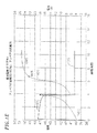
図1Aは、典型的な充電サイクル中の時間に対してグラフ化された、従来の鉄共振型充電器によって充電されている鉛蓄電池の端子における電圧と電流の様相のグラフである。このグラフ化された様相は電圧と、電流と、時間に対する電圧の第1および第2の導関数とである。こうした充電特性は、典型的には、鉛蓄電池を鉄共振型電池充電器で充電するときに観察される。鉄共振型充電器は、典型的には、電流128と電圧101が電池充電事象中に変化する仕方を記述する曲線の明確な形状を与える変圧器/整流器回路を含む。充電サイクルを実現する際に、充電サイクルの持続時間と、再充電エネルギーが電池に与えられる速度とが、電池に戻される充電量を決定する。開放型鉛蓄電池を完全充電するために、使用される典型的な方法は、電池に流れ込む充電電流が大きく減少した状態にその電池が達した後にも、その電池に充電し続けること、すなわち、過充電することである。
【0023】
直前のデューティサイクル中に鉛蓄電池から取り除かれたアンペア時の固定パーセント値にその鉛蓄電池の過充電を制御することが、典型的には、電池の寿命を著しく増大させる傾向がある。過充電パラメータは、典型的には、当業者に公知の様々な基準に基づいて選択される。このように先行のデューティサイクル中に取り除かれたアンペア時の固定パーセント値に充電される電池は、電池の総充電容量の固定パーセント値として設定された量の過充電を充電毎に受ける類似の電池よりも長い有効寿命を有するだろう。したがって、再充電開始時の初期電池放電状態の知識と使用は、最適な形で電池に供給される過充電の量の決定に役立つ。
【0024】
鉛蓄電池の充電中の電圧応答101が図1Aに時間の関数として示されている。測定された電圧は、充電サイクル中の様々な時点における電池の両端子間の電圧である。印加された充電電流128の特定の値に応答した電池の各充電サイクルに関する特有の電圧応答101が、その電池の温度と、通常は電池の古さの関数である内部条件とに応じて変化する。電池の温度と古さは両方とも、典型的な充電装置によっては認識されない。したがって、充電器に接続された電池の充電不足量を判断するための基礎は、確実な形で電圧の絶対値に基づいていることはないだろう。
【0025】
電池の充電不足量のアンペア時の判定は、より確実性が高い形で開放型鉛蓄電池の特有の電圧−時間特性に基づいている。使用されることが好ましいこの特有の電圧−時間特性(図1Aを参照されたい)は、時間の関数としての電圧V(t)(曲線101)と、時間に対する電圧の変化の速度dv/dt(曲線104)と、時間に対する電圧の加速度d2v/dt2(曲線106)である。
【0026】
電池の両外部端子の間で測定される電池電圧V(t)(図1Aの曲線128)は、印加される充電電流I(t)に応答して充電サイクル中に変化する。充電中の電池の両端子間の電圧と、電池の中に流れ込む充電電流は、充電サイクル中に通常は変化する電池の内部抵抗と逆起電力(開回路電圧)とに関係付けられている。
【0027】
特定の時点において、電池の内部抵抗が、電池の電解質中に配置されている電池のセル構造を構成する一連の導電性要素によって決定される。充電サイクルの開始時に、すなわち、t=0(図1Aの点116を参照されたい)において、初期電池電圧Viは開回路電圧である。充電サイクルの開始時には、充電器によって供給される電流は、典型的には、充電サイクル中のその最高値Ii(点126)にある。
【0028】
典型的な充電プロセス中は、電池電圧101は最初は低い値Viにあり、急速に中間の電圧に上昇して、この中間の電圧から一定の時間期間にわたってゆっくりと上昇し続け、その後に、次第に傾きを増大させながら再び急速に上昇し、最後には最終的な完全充電電圧Vtに達する。電池が充電されるにつれて、充電プロセス中に発生させられる熱と、電解質の比重の増大とのために、電池の逆起電力が大きくなる。電池が充電されるにつれて、充電器によって供給される電流128が、電池電圧101が電池インピーダンスの増大に伴って増大するのに応じて減少する。
【0029】
充電の最終段階では、与えられたエネルギーに応答して電解質が分解することに応じて、水素気体と酸素気体の電解生成によって電池の逆起電力のさらなる増大が引き起こされる。この現象は「ガス放出」と呼ばれている。電池が完全充電状態に近づいて、この状態に達する時に、ガス放出が起こり、その電池の構成要素は再生の形で再充電エネルギーを受け入れることができなくなる。ガス放出プロセスが安定化すると、電池の両端子間の電圧が本質的に一定不変の状態のままとなり、その最終値に近づく。
【0030】
充電の最終段階では、電解質攪拌効果のために、電池端子電圧101のわずかな増大が見られる。この電解質攪拌効果は、ガス放出プロセスによって引き起こされる。この攪拌効果は、電池内の一連のセルの各セルの中の電解質が実質的に均質になること、すなわち、均一な比重(酸濃度)になることを引き起こし、各セル内の電池逆起電力を安定させる。多くの場合、所望の充電プロセスを実現するために電池の内部構造と充電プロセスとを考慮に入れる電池充電システムを設計することが望ましい。
【0031】
電池充電器は、様々なタイプの回路設計を使用して構成される。充電器の回路設計は強磁性技術およびスイッチング技術を含む。電池充電器の回路設計に適合した「プロファイル」または「アルゴリズム」と呼ばれる1つまたは複数の充電プロセスを提供するために、様々なタイプの電池充電器も設計されている。さらに、プロファイルは、電池寿命を延長する試みとして充電中の電池内の内部変化を利用するために選択されることが多い。
【0032】
dv/dt=0に合わせられた終了方式を有する充電器は、典型的には、電池から以前に取り出された電荷の118%から124%を供給する。
【0033】
続けて図1Aを参照すると、時間に対する電圧の第1の導関数104と第2の導関数106が、電池の所望の充電要件に関する追加の情報を提供する。さらに、第1と第2の電圧導関数は、容易に検出される明確な状態の遷移を与える。この第1と第2の導関数によって提供される情報は、個々の電池に特有の信頼性の高い基準を提供し、したがって充電プロファイルがその特定の電池に合わせて調整されることも可能である。電圧応答101曲線の第1の導関数104と第2の導関数106との選択された様相に電池の充電プロセスを基づかせることによって、特定の充電事象中における特定の電池に適合した過充電量を与えるために電池の固有かつ個別の充電要件を計算に入れる充電プロセスが実現できる。
【0034】
図1Aでは、従来の鉄共振型充電プロセスによって制御される充電サイクルを受ける開放型ディープサイクル鉛蓄電池の一例の電圧特性V(t)が、曲線101によって示されている。充電サイクルの終わりには、電圧曲線101とその第1の導関数(dv/dt)104と第2の導関数(d2v/dt2)106との間の相互関係が、電池が完全充電状態に匹敵する特定の状態にある時点の有用な表示を提供することが可能である。開放型鉛蓄電池に関するこの特定の状態とは、電池が完全充電の約98%にある状態である。図1Aでは、この状態はグラフの水平な時間基線上の点108によって示されている。
【0035】
電圧曲線101では、電圧は充電サイクルの終わりまで時間経過に応じて増大する。充電サイクルの終了の前に、この電圧曲線は頭打ちになって減少するまで急速に上昇する。この急速な増大の最中に、曲線101は、電圧が加速を止めて減速し始める変曲点115を有する。V(t)の第1の導関数をプロットする対応する曲線104では、V(t)の第1の導関数の最大値114が、V(t)の変曲点115の発生と同時に生じる。電圧曲線101の第1の導関数(dV/dt)は再びピークに上昇することはない。dV/dtのこの最大値114は、電圧変曲点115の場合よりも正確な98%充電点108の表示を与える。
【0036】
鉄共振型充電を受ける鉛蓄電池の第1の導関数(dv/dt)における変化、すなわち、「電圧」対「時間」の変化の速度を表す曲線104は、2つの応答ピークを有する曲線106によって特徴付けられている。最初に、第1の導関数104は、急激に変化する電池電圧に対応する高い値を有する。その次に、変化が小さい期間を電圧曲線101が通過するときに、電池電圧の変化の速度の曲線104が減少する。変化の速度の小さな値の後に、114でピークに達してから低下する変化の速度の第2の急激な減少が続く。ピーク114は電圧曲線101の変曲点115に対応し、この変曲点において最大の傾きが測定される。電圧が最も急速に変化している「電圧」対「時間」曲線101における変曲点115は、第1の導関数の曲線104上に対応する最大値114を有する。第1の導関数が最大値に達した後に、電圧101の変化速度104が減少する。
【0037】
鉄共振型充電を受ける鉛蓄電池の「電圧」対「時間」関数の第2の導関数(d2v/dt2)が曲線106によって示されている。この第2の導関数は曲線104の変化の速度を表し、一方、この曲線104は電圧変化の速度を表す。したがって、曲線106は、電池端子に加えられる電圧の値が電池充電プロセス中にどのように加速したり減速したりするかを表す。第2の導関数106から分かるように、第1の導関数の曲線104が上述の最大値114のようなその曲線の傾きが瞬間的にゼロに等しい点に達するときに、第2の導関数はゼロである。
【0038】
第1の導関数が最大値に達しかつ第2の導関数がゼロの値を有する時間上の点が、電池から以前に取り出されたアンペア時の98%がその電池に戻され終わった時間上の点108を非常に正確に識別する。正値から負値への第2の導関数(d2v/dt2)の急激な変化は、第1の導関数の値における漸進的変化よりも容易に識別される。
【0039】
曲線106上の点108は、この特徴が個々の電池の初期放電状態と古さと温度との特性に関係しているので、異なる電池において異なる時間(t)に発生する。しかし、点108は、印加された電流128のほぼ全部が気体を発生させるのために使用されている充電プロセス中の時点に相当する。この時点は本発明の実施において信号として使用され、および、当該の再充電事象の開始から測定された、その点において電池に戻され終わっている充電が、信号充電QSと呼ばれる。QSの大きさと電池完全充電QFに対するその関係との知識が、所望の過充電量QOと共に、供給可能な(供給される)総充電QDが求められることを可能にし、および、これにしたがって充電プロセスが制御されることを可能にする。電池が80°Fにおける開放型鉛蓄電池である場合には、QS=0.98QFである。電池が何らかの他の温度である場合には、QS対QFの関係は異なっている可能性があるが、電池温度が室温よりも著しく低い温度ではないならば、関係QS=0.98QFの使用が実行可能であり、かつ、大きな改善をもたらすことが発見されている。
【0040】
電池に供給される充電はアンペア時(「amp-hours」)単位で測定されることが可能である。1アンペア時は、1アンペア電流によって1時間で電池に供給される充電の量である。したがって、アンペア時単位で指定された充電容量を有する完全に放電された電池は、1アンペアの充電電流において、容量に対する完全充電状態または完全充電の所望の部分に電池を戻すために、その指定されたアンペア時容量に等しい時間数を要するだろう。
【0041】
完全充電QFを超えた指定された過充電量QOが、電池寿命の増大を実現するために選択される。一例としての実施形態では、この過充電量は補充充電QRの108%として選択される。すなわち、図1Aでは、Xが、補充充電よりも8%多い充電が電池に供給され終わった時点であり、および、この電池に関する再充電事象が終了させられる時点である。
【0042】
所望のコンディショニングを実現するために有効に電池に戻される充電量が、次の関係によって得られるだろう。
(指定された過充電%)(充電開始から完全充電の98%までのアンペア時)=(指定された過充電に達するための初期充電からのアンペア時)(98%))。
上記で定義した術語を使用して別の形で表現すると、
QS/0.98=QD/(1+x) (式1)
ここでxは、過充電量として電池に供給されるべき補充充電QRのパーセント値に等しい小数である。xの使用可能で好ましい値は0.10である。
【0043】
図1Aの時間T、すなわち、点112が、電池が完全充電されている、すなわち、電池が充電レベルQFを有する時間上の点である。充電量QSは、第2の導関数のゼロ横断を求めることから得られる。したがって、充電特性曲線の動的な様相の分析によってQSが求められれば、再充電事象中に供給されるべき総充電QDが得られるだろう。
【0044】
この液体電解質の気体攪拌によって所望の度合いのコンディショニングを得るために電池に供給されるべき過充電の量は、好ましくは約8%から約12%の範囲内であり、最も好ましくは約10%である。
【0045】
図1Bと図1Cはそれぞれにカ氏80度とカ氏122度における電池の充電プロファイルに関するグラフである。所望のあらゆるプロファイルが使用可能であるが、好ましいプロファイルは定電力プロファイル(constant power profile)である。これらのグラフの場合には、電池は、それぞれの充電事象の開始前に135アンペア時または136アンペア時を供給した。充電不足量の98%または他のパーセント値が電池に戻され終わった時間上の点が、各グラフ上に記されている。カ氏122度の温度を有する高温の電池が、充電電圧の第2の導関数がゼロの値になる時よりも時間的に早く、0.98QF信号点に達する。しかし、完全充電の98%に対するd2v/dt2=0の発生における温度ベースのずれはわずかである。こうした非常に高温の電池に関してQS=0.98QFを使用することが、そうでない場合に生じるであろう電池の過充電よりも著しく少ない電池の過充電を結果的に生じさせる。
【0046】
図1Dと図1Eはそれぞれにカ氏80度とカ氏48度とにおける電池の充電プロファイルに関するグラフである。これらのグラフの場合には、電池は充電事象の開始前に81アンペア時と82アンペア時とを供給した。QC=0.98QRとQC=1.09QRである時間上の点が各グラフに記されている。これらのグラフから分かるように、低温の電池の信号点は電圧曲線に沿って右にずれている。例えば、低温の電池は、充電電圧の第2の導関数がゼロの値である時間上の点において完全充電の98%未満であるだろう。この低温の電池に関する電圧の第2の導関数がゼロの値であるときには、完全充電の82%だけしか電池に戻されていない。こうした状況では、関係QS=0.98QFの使用は電池に対するある程度の充電不足量を生じさせるが、電池を著しく損なうことはない。典型的な工業用の温度範囲に関して、d2v/dt2=0の時点において電池に戻される充電のパーセント値は、典型的には、その総充電容量QFの84%から102%まで変化するだろう。
【0047】
温度をプロセスに要因として含める(factor)簡単な方法が、温度を直接測定してプロセス中の要因としてそれを含むことである。しかし、電池の内部温度を測定するのに効果的である温度センサを追加することは高コストであり、向上した信頼性を有する低コストの充電システムを生産する上で望ましくない別のレベルの複雑性を典型的な充電システムに付加する。
【0048】
図2が、鉛蓄電池のための充電プロセスの一例の流れ図である。電池の98%充電点に対応する第1および第2の導関数の情報を求めて利用するために、適切な情報を求めるためのプロセスが実行される。こうしたプロセスは、例えば、電池充電システムを備えておりかつ好ましくは電池充電器の一部分であるコンピュータやマイクロプロセッサや他の制御装置を駆動するプログラム命令セットとして具体化される。この命令は揮発性または不揮発性メモリ内に記憶されるか、または、大容量記憶媒体上に記憶されることが可能である。
【0049】
この充電プロセスの開始時には、充電プロセスを開始させるためにコマンドが始動される202。その次のステップ204では、タイマ回路が始動される。代案のプロセスでは、タイマ回路が、動作または動作シーケンスを計時するようにマイクロプロセッサに指示するために使用されるソフトウェアのようなソフトウェアの形で具体化されることが可能である。所望の電圧条件に達した時に経過時間が分かるように、時間がステップ206で記録される。その次に、電圧の第1の導関数と電圧の第2の導関数との監視がステップ208で起動される。第2の導関数の値がステップ210で評価される。第2の導関数がゼロに等しくない場合には、そのプロセスが、ステップ208において、第2の導関数を監視し続ける。第2の導関数がゼロに等しい場合には、そのプロセスはステップ212で行われる評価に進む。ステップ212では、電圧の第1の導関数が、その導関数が最大値に達しているかどうかを判定するために監視される。第1の導関数が最大値に達していない場合には、ステップ208においてその第1の導関数が続けて監視される。ステップ212でdv/dtが最大値であると判定される場合には、プロセスの流れが分岐してステップ214に進む。ステップ214では、完全充電の98%に達するための測定された時間が適用され、および、追加の充電時間が、所望のパーセント値の過充電が電池に加えられるように計算される。ステップ214の実行は、QSを計算するために、および、上述の関係と、x(過充電パーセント値)およびQS/QFの所望の値を定義するプログラムパラメータとを使用してQDを計算するために、タイマからの情報と、電池に供給された合計アンペア時に関する情報とを使用することを含む。
【0050】
本発明の実施形態では、ステップ210、212で行われる評価は、その充電プロセスの結果に影響を与えることなしに相互交換されてもよい。さらに、一例としてのステップ212で行われる電圧の第1の導関数の最大値の判定が連続的に行われてもよく、または、当業者に公知のサンプリング方法を使用して行われてもよい。
【0051】
充電サイクルの開始からd2v/dt2=0までの初期充電時間が求められ終わり、および、ステップ214で所望の過充電を与えるための追加の時間量が計算された後に、プロセス(ステップ216)は、所望の過充電を与えるための追加の時間量にわたって電池が充電されるようにする。追加の充電時間が経過し終わった後に、充電サイクルがステップ218で停止される。
【0052】
本発明による電池再充電プロセスが終了されなければならない時点を判定するのに有用な関係は次の通りである。
Q S = Q D
.98 1+X
ここで、QSとQDは上記定義の通りであり(用語解説を参照されたい)、xは、電池の所望のコンディショニング(電解質攪拌)を得るために完全充電後に電池に加えられるべき補充充電QRのパーセント値に等しい小数である。
【0053】
電池の完全充電が1000であり、および、所望の過充電パーセント値が8%であると仮定する。電池が再充電事象の開始時に50%放電されている場合には、QS=0.98(1000−500)=490であり、したがってQD=540である。Qi+QD=500+540=1040であり、したがって再充電事象の終了時における実際の過充電の量は40である。
【0054】
再充電が始まるときに容量の25%(Qi=250)である電池に同じ仮定を適用すると、QS=0.98(1000−250)=735、QD=810、および、Qi+QD=250+810=1060であり、したがって供給される過充電は60である。同様に、再充電が始まるときに電池が容量の70%である場合には、QS=0.98(1000−700)=294、QD=324、および、Qi+QD=700+324=1024であり、したがって供給される過充電は24である。
【0055】
電池の再充電事象が始まる時に電池が非常に深く放電されている場合には、酸電解質の高度に希釈された状態のせいで酸電解質の比重が低い(1.00付近)ということが想起されるだろう。再充電が始まる時に電解質が希薄であればあるほど、完全充電時の電解質の密度の層状化が著しいだろうし、したがって、電池セル全体にわたって電解質を実質的に均質にすることによって電池を適正にコンディショニングするために、電解質がガス発生によって攪拌される必要が増すだろう。これとは逆に、電池の再充電事象が始まる時に電池が比較的浅く放電されている場合には、酸電解質はより高い開始比重を有し、完全充電時の密度の層状化がより小さく、および、電池を適切にコンディショニングするための電解質攪拌の必要性はより低いだろう。上述の例は、本発明が、適正なコンディショニングのために必要であると判定されておりかつ電池を極めて大幅に過充電しない量の過充電だけを、再充電される電池に供給するということを示す。電池の過充電の量は、再充電が始まる時の電池の放電状態の関数である。再充電プロセスが終了する時点は、電池自体から得られる情報から決定される。それは、図2−7に示されている電池再充電プロセスの特性である。
【0056】
図3Aと図3Bは、セル電圧を監視する充電プロセスの流れ図である。ステップ302−316がステップ202−216と同じであることが可能である。しかし、このプロセスでは、特定の最低条件が満たされなければ充電が終了させられない。一例としての実施形態では、セル電圧がこうした最低条件の1つである。ステップ318では、セル電圧が監視される。セル電圧が例えばセル1つ当たり2.45ボルトに達すると、充電アルゴリズムがステップ320で終了させられる。この代わりに、他のセル電圧が他のタイプの電池のために使用されてもよい。
【0057】
セル電圧がセル1つ当たり2.45ボルトに達していない場合には、このプロセスが図3Bの文字Aに分岐する。このプロセスでは、充電は、デフォルトとして、第1の導関数電圧がゼロになるまで充電プロセスを終了させない状態になる。したがって、充電はステップ322で継続する。充電中には、第1の導関数がステップ324で評価され続ける。第1の導関数がゼロに達する場合には、充電プロセスがステップ326で終了させられる。第1の導関数がゼロに達しない場合には、第1の導関数がゼロに達して充電プロセスが終了させられるまで、充電プロセスが続く。
【0058】
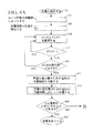
図4Aと図4Bは、所望の過充電を生じさせるためにセル電圧と充電時間とを監視する充電プロセスの流れ図である。このプロセスは、図3のプロセスの代案の実施形態である。図4Aに示されているプロセスは図3Aのプロセスと類似しており、ステップ402−426はステップ302−326と同じであることが可能である。しかし、このプロセスでは、充電は、特定の最低条件が満たされなければ終了させられない。セル電圧がこうした最低条件の1つであることが可能である。ステップ418では、セル電圧が監視される。
【0059】
図4Aと図4Bとに示されているプロセスは、特定の用途で望ましいと考えられるように、充電が特定の時間数の内に完了させられていない場合に充電サイクルを終了させるというさらに別の代替策を提供する。ここで説明している実施形態では、16時間が完全充電を完了させるための最大時間数であると考えられている。この代案として、電池に対するダメージを防止するのに適した任意の時間期間が代わりに採用されてもよい。
【0060】
図4Bを続けて参照すると、充電プロセスがステップ422で継続し、一方、第1の電圧導関数がステップ424で監視される。第1の導関数がゼロに達すると、充電プロセスがステップ426で終了させられる。第1の電圧導関数がゼロに達していない場合には、充電プロセスが、経過した充電時間を設定時間(この場合には16時間)と比較する評価ステップ428に分岐する。一実施形態では、任意の適切な時間期間が設定時間として選択されてよい。
【0061】
予め決められた充電時間を超えた場合には、警報信号または警報メッセージが視覚的に、音声によって、または、他の方法で、電池充電プロセスを担当しているか監視している係員に送られることが可能である(ステップ430)。このメッセージは、ゴルフカー集団内の各ゴルフカーの電池が同時に再充電されているときのように、存在している可能性がある他の充電器から当該の充電器を区別するために、当該の充電器の識別属性に関する情報を含むことが可能である。ステップ430における警報信号の発動時には、充電サイクルがステップ432で終了させられる。ステップ428において、予め決められた時間が未だ経過し終わっていない場合には、充電サイクルが継続する。
【0062】
図5は、リフレッシュ充電を提供する充電プロセスの流れ図である。ステップ502−516がステップ402−416と同じであることが可能である。充電プロセスはステップ518で終了させられることが可能である。
【0063】
電池がまだ充電器に接続されている状態で、ステップ520で電池の開回路電圧が監視される。電池の電圧が事前設定された最小値VMinよりも低下する場合には、充電プロセスが繰り返されることが引き起こされる。電圧VMinは、充電器が電池がその閾値よりも低下することを許可しない所望の低い方の電圧閾値を与えるために選択される。充電器は電池上の電荷をVMinよりも高いように保つ。しかし、電池が低い電圧閾値VMinよりも高いままである限りは、充電プロセスは再開されず、充電プロセス全体がステップ522で停止させられる。VMinのために選択される値は、ユーザによって選択可能である許容可能な残存充電の量、または、その代案として、充電操作プログラムにおける事前設定値としてプログラミング可能な許容可能な残存充電の量に基づいている。
【0064】
図6は、電池の充電終了時から経過した時間と電池の開回路電圧とを監視する充電プロセスの流れ図である。ステップ602−618はステップ502−518と同じであることが可能である。電池の充電終了時から経過した時間と電池の開回路電圧とを監視するこの充電プロセスでは、電池充電プロセスの終了時から経過した時間がステップ622で監視される。予め決められた量の時間が充電プロセスの終了時点から経過し終わっており、かつ、電池が充電器装置に接続され続けている場合には、充電プロセスが再開される。経過した時間が予め決められた量の時間を超えていない場合には、充電プロセスがステップ624に進む。開回路電圧がその予め決められた値VMinよりも低い場合には、充電が再開される。電池開回路電圧がVMinよりも高いままである場合には、充電プロセスがステップ626で終了させられる。
【0065】
代案のプロセスでは、開回路電圧が、充電プロセスの終了時点から経過した時間を評価する前に監視されることが可能である。さらに別の代案のプロセスでは、充電プロセスの終了時点からの時間が、電池の開回路電圧の監視と同時に監視されることが可能である。
【0066】
図7は、様々な充電プロファイルの選択を可能にする本発明の一形態の流れ図である。ステップ702で充電プロセスが開始される。その次に、充電プロファイルが選択される704。採用可能な充電プロファイルは、定電位、変更された定電位、定電流、鉄および鉄共振(ferro and ferro resonant)、定電流−定電位−定電流(IEI)、定電力−定電位−定電流(PEI)、並びに、好ましくは定電力を含む。この異なるプロファイルを記述し定義する情報が、充電器の制御様相に関連して充電器内に含まれたアドレス可能メモリ内に格納されることが可能である。
【0067】
充電プロファイルが選択され終わると、タイマ回路が初期値にセットされ、その選択されたプロファイルを使用する充電プロセスがステップ706で開始される。その次に、ステップ708で充電プロセスが経過時間を記録し始める。ステップ710において、充電プロセスは電圧の第1と第2の導関数を監視する。第2の導関数がゼロに等しく(ステップ712)かつ第1の導関数が最大値に達している(ステップ714)場合には、充電プロセスが継続する。第2の導関数がゼロに達しておらずかつ第1の導関数が最大値に達していない場合には、これらの値がその所望の値に達するまで、これらの値が連続的に監視される。
【0068】
所望の導関数値に達すると、所望の過充電のための追加の充電時間がステップ716で計算され、電池が所望の過充電を得るために追加の充電時間にわたって充電される(ステップ718)。この追加の充電時間は、以前に選択された充電プロファイルまたは別の充電プロファイルを使用してもよい。所望の過充電のための追加の充電時間が経過し終わると、充電プロセスがステップ720で終了させられる。
【0069】
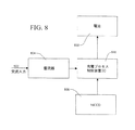
図8は、充電制御アルゴリズム装置ICと、適切にプログラミングされたマイクロプロセッサのような「測定/計算/制御装置」(MCCD)とを使用する、電池充電システムの一例のブロック図である。整流器804に対する交流入力802が、充電プロセス制御装置集積回路808を通して電池810に印加される充電電流を所望の電圧において発生させる。この充電プロセス制御装置集積回路808は、電池810に対する充電エネルギーの印加を制御する。
【0070】
充電制御装置IC 808は、1つまたは複数の充電プロファイルまたは充電プロセスを含む充電信号を印加するために、MCCDと共に機能する。図2から図7に示されているプロセスの1つまたは複数を実施するための命令がMCCD 806内に記憶されることが可能である。典型的には、この記憶は、充電プロセスを記述する1組のプログラム命令をMCCD内にロードすることによって実現される。この代案として、充電プロセスは、集積回路808の特徴と機能とを含むことが可能な専用の充電プロセス制御集積回路の形に統合されてもよい。
【0071】
図9は、電池を充電するための本発明の充電プロセスの1つまたは複数を実施することが可能な電池充電システムのブロック図である。交流入力902がリレー912によって制御される。リップル成分を有する直流電圧を生じさせるために、交流電力が整流器904に供給される。電圧調整器906が直流電圧の変動を減少させる。調整された直流電圧が、リレー914の接点を通して電池916に所望の電流と電圧を供給するために、従来通りに構成された電流制限装置910と共に働く従来通りに構成された直列通過素子(series pass element)908に印加される。電池に印加される電流は従来通りの電流計918によって監視される。この電流計は導体内を流れる電流の瞬間値を監視する。代案の構成では、従来の平均電流計が、導体を通過する平均電荷を表示するために使用されることが可能である。さらに別の代案の構成では、従来の総合電流計が、導体を通過する総電荷の表示を与えるために使用されることが可能である。電池の両端子間の電圧が電圧計920によって監視される。電流計と電圧計とから得られた情報がMCCD 806に与えられることが可能である。
【0072】
電池916の両端子間の電圧は、さらに、電圧の第1の導関数を計算する微分器回路922にも供給される。こうした回路は、930に示されているように従来通りに構成されていることが可能である。微分器は、典型的には、微分器を構成するように当業者に公知の通りに接続されている演算増幅器Aと抵抗器RとコンデンサCとを備える。電圧Viが微分器の入力に印加される。信号出力VOは−RC(dV/dt)に等しい。
【0073】
第1の導関数回路922の出力がピーク検出器928に送り込まれる。最大の第1の導関数の信号が検出されると、その表示がMCCD 806に与えられる。第1の導関数の処理回路の出力は、第2の導関数の処理回路924にも供給される。この回路は単純に922の回路の複製である。第2の導関数の回路924の出力がゼロ横断検出器926に送り込まれる。ゼロ横断検出器は、電圧が正から負へ変化し必然的にゼロボルトの値を通過する時のような信号極性の遷移を検出する回路である。図1の電圧曲線101における変曲点115の検出に対応するゼロ横断の検出が求められる。ゼロ横断検出の表示がMCCD 806に与えられる。本発明の実施形態を含むプロセスの制御によって、MCCDは充電電流と充電電圧とがリレー914を通して印加されるようにその充電電流と充電電圧とを送り出す。MCCDは、さらに、リレー912によって交流入力の動作を制御することもできる。
【0074】
図9に示されている充電システムの構成要素が共通の充電器ハウジングの中に収容されていることが好ましい。充電器は、一般的に、電池、または、電池が中に配置されている物品(例えばゴルフカー)から分離していることが可能であり、一般的に分離している。しかし、必要に応じて、充電システムの構成要素の一部または全部が、例えばゴルフカーの要素のような要素として電池に物理的に付随させられることが可能である。
【0075】
本発明が、電池寿命を低減させるほど電池を過剰に充電することなしに電池を効果的に充電する仕方でディープサイクルタイプの開放型鉛蓄電池を充電するための装置と手順を提供するということが理解されるだろう。この電池は、電池の最も最近の先行デューティサイクルの完了の後に電池を完全充電状態にするのに必要とされる充電エネルギーの選択されたパーセント値である量だけ過充電される。本発明の実施において実現される再充電事象は、本質的に、電池の古さと、充電の有効性と効率とに影響を与える電池内部特性とのような要因を考慮し計算に入れる。
【0076】
本発明が電池の再充電に関して上記で説明されてきたが、本発明が、電気ゴルフカーもしくは何らかの他の電動車両または装置において必要となる可能性がある1組の電池の再充電、または、例えば、光起電力システムと共に使用される1組の電池の再充電にも適用されるということが理解されるだろう。
【0077】
本発明の好ましい具体例および形態と他の具体例および形態との上述の説明が、本発明が有利に実現または使用されることが可能な装置または手順のすべての形態のカタログとしてではなく、一例として示されてきた。本発明が関わる分野の専門家は、上述の装置およびプロセスの変形と変更とが本発明の範囲から逸脱することなしに有益に使用されることが可能であるということを理解するだろう。
【図面の簡単な説明】
【0078】
【図1A】典型的な充電サイクル中の時間に対してグラフ化された、従来の鉄共振型充電器を用いて充電される鉛蓄電池の端子における電圧と電流の様相のグラフである。
【図1B】約135アンペア時のデューティサイクル放電の後の、カ氏80度における同様の電池の充電プロファイルに関するグラフである。
【図1C】約135アンペア時のデューティサイクル放電の後の、カ氏122度における同様の電池の充電プロファイルに関するグラフである。
【図1D】約81アンペア時のデューティサイクル放電の後の、カ氏80度における同様の電池の充電プロファイルに関するグラフである。
【図1E】約81アンペア時のデューティサイクル放電の後の、カ氏48度における同様の電池の充電プロファイルに関するグラフである。
【図2】開放型ディープサイクル鉛蓄電池に関する充電プロセスの実施形態の流れ図である。
【図3A】セル電圧を監視する充電プロセスの実施形態の流れ図である。
【図3B】セル電圧を監視する充電プロセスの実施形態の流れ図である。
【図4A】セル電圧と充電時間を監視する充電プロセスの実施形態の流れ図である。
【図4B】セル電圧と充電時間を監視する充電プロセスの実施形態の流れ図である。
【図5】リフレッシュ充電を実現する充電プロセスの実施形態の流れ図である。
【図6】充電終了時からの経過時間と電池開回路電圧とを監視する充電プロセスの実施形態の流れ図である。
【図7】様々な充電プロファイルの選択を可能にする本発明の実施形態の流れ図である。
【図8】充電プロセス制御装置ICと測定/計算/制御装置(「MCCD」)とを使用する電池充電システムの実施形態のシステムブロック図である。
【図9】電池を充電するために本発明のプロセスの実施形態を使用する電池充電器の実施形態のブロック図である。【Technical field】
[0001]
The present invention relates to a method for controlling the end of a recharge process for an open-type deep cycle lead acid battery. More particularly, the present invention relates to a procedure for supplying such batteries with an amount of recharge energy that is directly related to the amount of energy discharged after the most recent prior battery charging event. The invention further relates to an apparatus embodying such a procedure.
[Background]
[0002]
Various different types of rechargeable storage batteries are known, such as nickel cadmium batteries, nickel metal hydride batteries, nickel iron batteries, lithium batteries, silver cadmium batteries, and deep cycle lead acid batteries. Deep cycle lead acid batteries are different from SLI (starting, lighting, ignition) lead acid batteries such as those used in conventional automobiles, for example. SLI batteries are not designed or configured to withstand repeated cycles of significant charging and recharging, and are therefore not rechargeable batteries in the sense of the present invention.
[0003]
From patents such as U.S. Pat.Nos. 4,392,101 and 4,503,378 that the battery is in a fully charged state or that the battery has not reached a fully charged state but is relatively predictable It is known that certain features of rechargeable batteries that exist during battery recharging in a way that indicates that there are exist regardless of the type of battery. These patents and other publications are used to monitor this feature and to detect specific events, conditions and conditions of this feature and terminate the battery charging process or for a preset time. An apparatus and method for using this detection to continue charging across or in a preset manner is described. Such preset methods typically use a different charging process than the one used at the time of the detected event. Such a charge event detection method is known as an inflection analysis method, which is specified in a time-based curve that indicates, for example, changes in battery voltage or battery current during the charging process. This is because it is based on the detection of inflection points. The inflection analysis described to date is effective in controlling the recharging of most types of rechargeable batteries, but the inflection analysis as described above is not suitable for any case where the battery electrolyte is a gel. It has been found that it does not lend itself well to control recharging of an open deep cycle lead acid battery that is a liquid (typically sulfuric acid) that is not constrained in a support matrix.
[0004]
Open-type deep cycle lead acid batteries are widely used as an energy source for electric vehicles such as golf cars, forklift trucks, and scissor lift vehicles. This lead storage battery is further used in an uninterruptible power supply in hospitals and other buildings and facilities, and is used as a component of photovoltaic power generation equipment. The reason why the inflection analysis method as described above is not very useful for controlling the recharging of an open deep cycle lead acid battery can be understood from the use of such a battery in an example electric golf car. .
[0005]
An electric golf car is powered by a set of four or six open deep cycle lead acid batteries. Every golf course has a group of these golf cars available to golfers. Individual golf cars in this group may have older batteries than other golf cars in the group. Certain golf cars may be used more frequently than other golf cars. Some golf cars may be used longer than other golf cars by day. Some golf cars are subject to more severe usage conditions than other golf cars from day to day, depending on the conditions of the golfer using them, the differences in the terrain that they have traveled, and other reasons. In addition, even if all the batteries in a golf car population are from the same manufacturer and are the same nominal age, it can affect battery performance and life, And it is known that there are still significant differences between batteries of the kind that can affect how the batteries respond to the recharging process. Therefore, at the end of the day when golf cars in the group are to be recharged, there can be a large difference between the discharge states of the batteries for each golf car, so There can be significant differences among golf cars as to how they need to be charged. A uniform recharge procedure across the population will cause some batteries to be recharged inadequately, or even more likely, but the majority of the batteries will be significantly overcharged. Such significant overcharging of the battery reduces battery life. In general, humans employed to recharge golf car groups do not understand the effects of such significant overcharging and how to determine when overcharging occurs. Thus, batteries used in electric golf cars are recharged by devices and processes that avoid significant overcharge and inherent differences between batteries due to discharge conditions, age, manufacturing variations, etc. It is desirable to be recharged in a way that automatically absorbs and processes.
[0006]
Deep cycle lead acid batteries are designed to withstand repeated cycles of heavy discharge from a fully charged state and recharge from a discharged state to a fully charged state. Compared to other types of rechargeable batteries that do not use liquid electrolytes, liquid acid electrolytes in open-type deep cycle lead-acid batteries are a few batteries that are repeatedly used in combination with specific batteries or with each other. A special set of batteries that need to be recharged in a way that achieves a controlled overcharge, whose degree is related to the state of the battery at the time the recharge event is initiated Will bring about the conditions. In other words, effective recharging of an open deep cycle lead acid battery was ideally removed from the battery during the battery's most recent pre-duty cycle (the period of use since the most recent pre-charge event) ( It must include a controlled overcharge determined by the amount of energy (discharged). This reason is related to what occurs in the liquid electrolyte during the previous duty cycle and the subsequent recharge event.
[0007]
When the lead-acid battery cell discharges, the acid ions in the electrolyte move to the cell electrode, and oxygen atoms move from the cell active material into the electrolyte, forming water with the electrolyte hydrogen ions. Thus, the electrolyte acid gradually dilutes and its specific gravity gradually approaches 1.0 from the higher starting specific gravity. When the cell is recharged, its ion exchange process is reversed to cause regeneration of the electrolyte acid and active material. If the electrolyte is present in the cell as a free liquid as opposed to being present in the gel matrix (ie, the cell is open), the regenerated acid is dilute. Because it is heavier than electrolyte, it sinks to the bottom of the cell when it is formed. As the recharging process progresses, the regenerated acid that becomes increasingly concentrated collects at the bottom of the cell. When the cell active material has been completely regenerated, the cell is theoretically fully charged on a Coulomb basis. However, this cell is not suitable for use to supply stored energy due to electrolyte stratification. The electrolyte is not in a uniform acidity throughout the cell, and therefore the regenerated acid electrolyte is not in uniform effective contact with the regenerated active material over the entire area of the rejuvenated material. If the cell is required to discharge at this point, the electrochemical process of discharge will occur primarily in the lower portion of the cell where the electrolyte acid is excessively concentrated. The cell does not release energy at the desired level and the overconcentrated acid in the bottom of the cell will cause the adjacent active material to degrade too quickly. This results in insufficient cell performance in a manner that significantly reduces battery life.
[0008]
In the part of the recharge process of the lead acid battery cell that occurs just prior to full regenerative recovery of the active material, gas is generated in the cell as a normal part of the recharge process. This gas bubble rises to the top of the cell through the electrolyte and induces electrolyte circulation (stirring) in the cell during the process. However, if the recharging process is terminated at the time of complete regeneration of the active material, the amount of gas evolution that is occurring is determined by the ability to properly agitate the electrolyte and ensure uniform acid concentration (uniform specific gravity) throughout the cell. Is not enough to bring it to the electrolyte. For this reason, the recharging process of the open deep cycle lead acid battery is continued beyond the point of full charge, i.e. the gas generation process is extended over a period of time in order to obtain proper agitation of the regenerated electrolyte. This is a common practice. That is, the cell is intentionally overcharged.
[0009]
Current practice is to put several cells in a predetermined amount that is set to be adequate to sufficiently stir the electrolyte in one or more cells that require maximum agitation. Including overcharging such batteries. This pre-set amount of overcharge assumes that the cell has been fully discharged during its preceding duty cycle, and that the cell has certain attributes regarding age, condition and temperature. Based on. However, as indicated above in the description of the operation of an electric golf car group, this assumption is not appropriate for the majority of batteries that require recharging. As a result, relying on this assumption as to the amount of overcharge applied in the final stage of recharging of open deep cycle lead-acid batteries makes a significant number (if not most) of such batteries extremely overcharged. Cause it to be. The very large overcharge of such batteries significantly reduces the useful life of such batteries, especially when repeated over several times.
[0010]
The above description is to understand how inadequate the conventional description of the inflection analysis method for controlling the battery recharging process is when applied to the recharging of an open deep cycle lead acid battery. Provides the basis for
[0011]
U.S. Pat. No. 4,392,101 is an early description of the use of inflection analysis in controlling the recharging of a rechargeable battery. This patent teaches that rechargeable batteries generally have response characteristics that are roughly similar to the recharging process. This patent has a rough similarity in the resulting voltage / time curve or current / time curve when the battery voltage or current is plotted, for example, in graph form versus time during recharging. Teach you that. Regardless of the individual materials used to define the battery cells after the beginning of the charging process, these curves are at least a pair of curves in which the graph line reverses its curvature, i.e. is inflected. Will show inflection points. These inflection points indicate or represent different stages of the battery's response to applied charge energy, and for each cell type, this inflection occurs before the battery reaches full charge, or It has been shown that when a fully charged state is reached, it occurs at a relatively predictable point in the charging process. The predictability of inflection points is generally not affected by factors such as actual battery voltage, individual cell characteristics, individual charging history, or actual ambient temperature conditions (these factors). It has been clarified that it occurs regardless of This patent reveals that the inflection point can be identified by observing the state or characteristic of the first or second derivative with respect to time of the battery characteristic (voltage or current) being monitored. . More specifically, this patent states that the graph of the second derivative crosses the zero axis at least twice during the charging process (the sign of this derivative changes from positive to negative or vice versa). And a second zero-axis traversal of its derivative will occur when the battery reaches full charge or during a brief period of time just before full charge is obtained. Teach. However, that patent does not attempt to explain at what point the second time-based derivative of voltage occurs for full charge in the lead acid battery example. The main description of that patent relates to a nickel cadmium battery whose recharge is terminated after a predetermined time has elapsed since the second zero-axis crossing of the derivative was detected. Nickel cadmium batteries do not use variable concentrations of electrolytes that are present as part of the chemical process, so such batteries do not benefit from overcharge processing or require any overcharge processing. do not do.
[0012]
US Pat. No. 4,503,378 applies recharge control by inflection analysis to nickel-zinc batteries, and for this type of battery, recharge is the sign change of the second derivative of the battery voltage over time Disclose that it will be terminated at the occurrence of the second case (crossing the zero axis). Furthermore, the patent states that the value of the first derivative of the battery voltage with respect to time is at the maximum or peak value at the same time as the second derivative crosses the zero axis from positive to negative, and this fact is It states that the zero crossing of the second derivative can be confirmed.
[0013]
An article entitled "Charge a battery safely within 15 minutes by detecting a voltage inflection point" was published in the September 1, 1994 issue of EDM Magazine. This article focuses primarily on fast charging of nickel cadmium batteries. This article notes that inflection analysis applies to lead-acid batteries. In this context, this article states that "in lead-acid batteries, the second dV / dt inflection occurs in a predictable time period before the battery reaches full charge, but from the battery's ampere-hour capacity rating, It is possible to easily derive the duration of the incremental charge required to obtain the charge. " This description shows how to efficiently and reliably charge an open deep cycle lead-acid battery without extremely overcharging in view of the need for true recharging of the battery. It does not contribute to the solution of this problem for at least two reasons. First, the Ahr (ampere hour) capacity rating of a lead-acid battery is not an accurate value that can be accurately determined from engineering information. Rather, the ampere-hour capacity rating is a value that a manufacturer assigns to a battery model or type as a result of manufacturer-specific business factors such as factors such as marketing goals and warranty policies. A battery's “ampere-hour” capacity rating is only a manufacturer's statement regarding the predictable performance of the average battery of that type or type, perhaps under unspecified conditions. This “ampere-hour” capacity rating has a positive relationship to the need for charging a specific battery after the completion of a specific duty cycle, ie, the depth of discharge of the battery prior to undergoing a recharge event. Absent. Second, this “ampere hour” capacity rating is the value that needs to be obtained from a source other than the battery itself. What is needed is derived from the battery itself, which indicates the discharge state of the battery and can be used to overcharge the battery by the amount necessary to adequately agitate the regenerative electrolyte. It is a method of charging an open type deep cycle lead acid battery using information.
[0014]
Both the above-mentioned patents and the EDN Magazine article do not consider the state of battery discharge before the recharge process is initiated. They do not give knowledge about how information about the discharge state can be used to control the recharging of the battery. However, apart from these descriptions, it is known to physically attach an integrated ammeter (ampere hour meter) that always moves with the battery to a battery, such as a battery in a golf car. When a battery is connected to a charger after the battery duty cycle, the `` onboard '' ampere hour meter can communicate to the charger the value of the ampere hour removed from the battery during the most recent duty cycle The ampere hour meter is connected to the charger. The information is the total charge to be delivered to the battery by multiplying the measured value in ampere hours by the desired factor that has been found to cause sufficient agitation in the electrolyte (eg 1.10 or 110%). Is sent in the charger to a calculation / control device that calculates Then, the computing / control device in the charger monitors the ampere hours returned to the battery by the charger. When the calculated value for charge return is reached, the calculation / control unit instructs the charger to terminate the charging process. While this approach is effective, it has the disadvantage of increasing complexity by communicating data from the ampere-hour meter associated with the battery to the charger. This approach further increases costs because each battery or each operational set of batteries must be equipped with its own dedicated ampere-hour meter that must be specially constructed to withstand use within the battery environment. It also has the disadvantage of doing. This approach has nothing to do with inflection analysis and has obvious practical problems in this field.
[0015]
Therefore, they have little knowledge of battery technology to properly recharge open deep cycle lead acid batteries without significantly overcharging any one or small group of open deep cycle lead acid batteries. Clearly, there is a need to be able to use devices and procedures that can be used effectively and reliably by humans who have no or no. These devices and procedures effectively address and meet the need for actual recharging and electrolyte agitation of one battery or a limited small group of batteries to meet this need. There must be. The term “limited small group” is probably the same age, has the same usage history, and the time between the most recent recharge as a group and the recharge event in question. It refers to some batteries, such as some batteries installed in a particular electric golf car, that will share the same duty cycle during the period.
DISCLOSURE OF THE INVENTION
[Problems to be solved by the invention]
[0016]
In light of the above description, the present invention provides a procedure by which an open deep cycle lead acid battery can be recharged individually or in a limited small group in terms of actual recharge requirements and minimal overcharge process. In order to provide a device, a problem situation that has not been solved in the art is addressed. The present invention applies a new way of inflection analysis principle to customize each battery charging event to the needs of a battery or battery set for a charger including a novel computing / control device. This benefit and advantage is provided and realized effectively and reliably without requiring any changes in the way the battery is manufactured and used. Repair personnel are only required to connect and disconnect the charger from the battery. Information regarding recharge requirements is obtained by the charger from the battery itself during the charging process, without relying on an ampere-hour meter attached to the battery. That is, the charger does not know or need to know the state of discharge of the battery before the recharge process is initiated. The present invention protects the battery itself to the maximum and can extend the battery life.
[Means for Solving the Problems]
[0017]
With regard to the procedure, the present invention provides a method for charging a lead acid battery. The method includes monitoring the battery voltage during the charging process, recording the charging time, and monitoring the charge supplied to the battery in units of ampere hours. This method can also be provided between determining when the battery has a charge state that has a known relationship to the fully charged state and during the charging process and when the battery is fully charged. Determining the amount of charge energy that can be delivered to the battery beyond the point of full charge, equal to a desired portion of the energy.
[0018]
With respect to the structural aspects of the present invention, the present invention provides a charger for charging a lead acid battery, preferably a deep cycle lead acid battery. The charger includes a direct current source, a voltmeter, an ammeter, a timer, a dv / dt measuring circuit, d2v / dt2Measurement circuit.
[0019]
More specifically, the charger further includes a direct current source, an ammeter, a voltmeter, a timer, a dv / dt measuring circuit, and d.2v / dt2Including a control device connected to the measurement circuit. The controller determines a point in time during a battery recharge event where the battery is approximately at a predetermined percentage of full charge and a relationship (QS/ P) = [QD/ (1 + x)] to QDIn this relationship, QSD from the start of the charging event2v / dt2= 0 and ampere-hours of charge energy supplied to the battery during the time period up to the point where dv / dt is the maximum value, p isv/ Dt2A decimal number equal to the percentage value of supplementary charge supplied to the battery when = 0, x is a decimal number equal to the desired percentage value of supplementary charge to be supplied to the battery as an overcharge quantity, and QDIs the ampere hour to be supplied to the battery from the beginning of the charging event to reach the overcharge amount. If the predetermined percentage of full charge is 98%, p = 0.98.
[0020]
These and other features and advantages of the present invention will be better understood from the following detailed description which is to be understood with reference to the accompanying drawings.
[0021]
Explanation of terms
Full charge QF:
Battery condition where the battery is at full charge capacity and continuous application of charge energy has no beneficial effect on the electrode or electrode active material
Initial charge state Qi:
The remaining charge that the battery has at the beginning of the battery recharge event or recharge process
Replenishment charge QR:
The amount of charge energy, measured in ampere-hours, absorbed by a battery having an initial charge state to return the battery to a fully charged state. QR= GF-Qi
Insufficient charge:
The difference between the battery fully charged and the initial charge state. This is replenishment charge QRbe equivalent to.
Overcharge QO:
The amount of charge energy, measured in ampere-hours, that is delivered to a battery during the course of a recharge event or recharge process after the battery has obtained a full charge until the end of the recharge event or recharge process. This is the extra energy supplied to the battery to condition the battery for good performance during its next duty cycle. In the practice of the present invention, the magnitude of overcharging is directly related to the magnitude of supplementary charging.
Duty cycle:
The period during which a battery supplies energy during use of an article in which it is placed or connected after it has been fully charged. Charging a battery at the end of the duty cycle is the initial charge state of that battery during a subsequent battery recharge event or recharge process.
Coulomb charge QC:
The amount of charge a battery has at any given time.
Supply charge QD:
The ampere-hour of energy delivered to the battery during the time period between the start and end of the battery recharge event or recharge process. In the practice of the invention, this is a combination of replenishment ampere hours and overcharge ampere hours, i.e., QD= QR+ QOIt is.
Signal charge QS:
Beginning at the beginning of the recharge process, the battery has a detectable condition for the specific electrochemistry of the battery that indicates that the battery charge level has a clear relationship to full charge. The amount of charge measured in ampere-hours delivered to the battery during a time period that ends at a later time. In the context of the present invention related to lead acid battery electrochemistry, the detectable condition is a second time-based derivative of the battery voltage that coexists with a maximum of the first time-based derivative of the battery voltage. The zero value of
BEST MODE FOR CARRYING OUT THE INVENTION
[0022]
FIG. 1A is a graph of the voltage and current aspects at the terminals of a lead acid battery being charged by a conventional ferroresonant charger, plotted against time during a typical charge cycle. The graphed aspects are voltage, current, and first and second derivatives of voltage with respect to time. Such charging characteristics are typically observed when charging lead-acid batteries with ferroresonant battery chargers. Ferro-resonant chargers typically include a transformer / rectifier circuit that provides a well-defined curve that describes how current 128 and voltage 101 change during a battery charging event. In realizing a charge cycle, the duration of the charge cycle and the rate at which recharge energy is applied to the battery determines the amount of charge returned to the battery. To fully charge an open lead acid battery, the typical method used is to continue to charge the battery after the battery reaches a state where the charging current flowing into the battery is greatly reduced, i.e., excessive charge. It is to charge.
[0023]
Controlling the lead battery overcharge to a fixed percentage of ampere hours removed from the lead acid battery during the previous duty cycle typically tends to significantly increase battery life. The overcharge parameter is typically selected based on various criteria known to those skilled in the art. Thus, a battery that is charged to a fixed percentage of ampere hours removed during the preceding duty cycle is a similar battery that receives an overcharge of each amount set as a fixed percentage of the total charge capacity of the battery. Will have a longer useful life. Thus, knowledge and use of the initial battery discharge state at the beginning of recharging will help determine the amount of overcharge delivered to the battery in an optimal manner.
[0024]
The voltage response 101 during charging of the lead acid battery is shown as a function of time in FIG. 1A. The measured voltage is the voltage across the battery at various times during the charge cycle. The specific voltage response 101 for each charge cycle of a battery in response to a particular value of applied charge current 128 varies depending on the temperature of the battery and internal conditions that are usually a function of battery age. . Both battery temperature and age are not recognized by typical chargers. Thus, the basis for determining the amount of undercharge of a battery connected to a charger will not be based on the absolute value of the voltage in a reliable manner.
[0025]
The determination of the battery undercharge amount in ampere hours is based on the voltage-time characteristic peculiar to an open type lead-acid battery in a more reliable form. This unique voltage-time characteristic that is preferably used (see FIG. 1A) is the voltage V (t) (curve 101) as a function of time and the rate of change of voltage with time dv / dt ( Curve 104) and the acceleration d of the voltage with respect to time2v / dt2(Curve 106).
[0026]
The battery voltage V (t) measured between both external terminals of the battery (
[0027]
At a particular point in time, the internal resistance of the battery is determined by a series of conductive elements that make up the cell structure of the battery that is placed in the electrolyte of the battery. At the beginning of the charging cycle, ie at t = 0 (see
[0028]
During a typical charging process, the battery voltage 101 is initially low ViRapidly rising to an intermediate voltage, continuing to rise slowly from this intermediate voltage over a period of time, then increasing rapidly again with increasing slope, and finally the final Full charge voltage VtTo reach. As the battery is charged, the back electromotive force of the battery increases due to the heat generated during the charging process and the increased specific gravity of the electrolyte. As the battery is charged, the current 128 supplied by the charger decreases as the battery voltage 101 increases with increasing battery impedance.
[0029]
In the final stage of charging, the electrolysis of hydrogen gas and oxygen gas causes a further increase in the back electromotive force of the battery in response to the decomposition of the electrolyte in response to the applied energy. This phenomenon is called “gas release”. As the battery approaches a fully charged state and reaches this state, outgassing occurs and the battery components are unable to accept recharge energy in the form of regeneration. As the outgassing process stabilizes, the voltage across the battery terminals remains essentially constant and approaches its final value.
[0030]
In the final stage of charging, a slight increase in battery terminal voltage 101 is seen due to the electrolyte stirring effect. This electrolyte agitation effect is caused by the outgassing process. This agitation effect causes the electrolyte in each cell of a series of cells in the battery to be substantially homogeneous, that is, to have a uniform specific gravity (acid concentration), and the battery back electromotive force in each cell. To stabilize. In many cases, it is desirable to design a battery charging system that takes into account the internal structure of the battery and the charging process to achieve the desired charging process.
[0031]
Battery chargers are constructed using various types of circuit designs. The charger circuit design includes ferromagnetic technology and switching technology. Various types of battery chargers have also been designed to provide one or more charging processes called “profiles” or “algorithms” that are compatible with the battery charger circuit design. In addition, profiles are often selected to take advantage of internal changes in the battery being charged as an attempt to extend battery life.
[0032]
Chargers with termination schemes set to dv / dt = 0 typically provide 118% to 124% of the charge previously drawn from the battery.
[0033]
With continued reference to FIG. 1A, the first derivative 104 and the second derivative 106 of voltage over time provide additional information regarding the desired charging requirements of the battery. In addition, the first and second voltage derivatives provide a clear state transition that is easily detected. This information provided by the first and second derivatives provides a reliable reference specific to an individual battery, so that the charging profile can also be tailored to that particular battery. . Overcharge amount adapted to a particular battery during a particular charging event by basing the battery charging process on a selected aspect of the first derivative 104 and the second derivative 106 of the voltage response 101 curve. A charging process can be implemented that takes into account the specific and individual charging requirements of the battery to provide
[0034]
In FIG. 1A, a voltage characteristic V (t) of an example of an open-type deep cycle lead-acid battery that undergoes a charge cycle controlled by a conventional ferroresonant charging process is illustrated by curve 101. At the end of the charging cycle, the voltage curve 101 and its first derivative (dv / dt) 104 and second derivative (d2v / dt2) 106 can provide a useful indication of when the battery is in a particular state comparable to a fully charged state. This particular condition for an open lead acid battery is one where the battery is at about 98% of full charge. In FIG. 1A, this state is indicated by point 108 on the horizontal time baseline of the graph.
[0035]
In the voltage curve 101, the voltage increases with time until the end of the charging cycle. Prior to the end of the charging cycle, this voltage curve rises rapidly until it peaks and decreases. During this rapid increase, curve 101 has an inflection point 115 where the voltage stops accelerating and begins to decelerate. In the corresponding curve 104 plotting the first derivative of V (t), the
[0036]
A curve 104 representing the rate of change in the first derivative (dv / dt) of a lead-acid battery undergoing ferroresonant charging, ie, “voltage” versus “time”, is represented by a curve 106 having two response peaks. It is characterized. Initially, the first derivative 104 has a high value corresponding to a rapidly changing battery voltage. Then, as the voltage curve 101 passes through a period of small change, the battery voltage change rate curve 104 decreases. A small value of the rate of change is followed by a second rapid decrease in the rate of change that decreases after reaching a peak at 114. The
[0037]
The second derivative of the “voltage” versus “time” function (d2v / dt2) Is shown by curve 106. This second derivative represents the rate of change of curve 104, while this curve 104 represents the rate of change of voltage. Thus, curve 106 represents how the value of the voltage applied to the battery terminal accelerates or decelerates during the battery charging process. As can be seen from the second derivative 106, when the curve 104 of the first derivative reaches a point where the slope of the curve instantaneously equals zero, such as the
[0038]
The point in time at which the first derivative reaches a maximum value and the second derivative has a value of zero is above the time at which 98% of the ampere-hour previously removed from the battery has been returned to the battery. Are identified very accurately. The second derivative from positive to negative (d2v / dt2) Is more easily identified than a gradual change in the value of the first derivative.
[0039]
The point 108 on the curve 106 occurs at different times (t) in different batteries because this feature is related to the initial discharge state and age and temperature characteristics of the individual batteries. However, point 108 corresponds to a point in the charging process where almost all of the applied current 128 is being used to generate gas. This point is used as a signal in the practice of the present invention, and the charge measured at the beginning of the recharge event, at which point has been returned to the battery, is signal charge QSCalled. QSSize and battery full charge QFKnowledge of its relationship to the desired overcharge amount QOTotal charge Q that can be supplied (supplied)DCan be required and the charging process can be controlled accordingly. If the battery is an open lead acid battery at 80 ° F., QS= 0.98QFIt is. Q if the battery is at some other temperatureSVs QFMay be different, but if the battery temperature is not significantly lower than room temperature, then the relationship QS= 0.98QFHas been found to be feasible and provide significant improvements.
[0040]
The charge delivered to the battery can be measured in ampere-hours (“amp-hours”). One ampere hour is the amount of charge supplied to the battery in one hour with one ampere current. Thus, a fully discharged battery having a specified charge capacity in ampere-hours is designated to return the battery to full charge state for the capacity or the desired part of full charge at a charge current of 1 ampere. It would take hours equal to the ampere hour capacity.
[0041]
Full charge QFSpecified overcharge amount Q exceedingOAre selected to achieve increased battery life. In an exemplary embodiment, this overcharge amount is a supplemental charge QROf 108%. That is, in FIG. 1A, X is the time when 8% more charge than the replenishment charge has been supplied to the battery, and the time when the recharge event for this battery is terminated.
[0042]
The amount of charge that is effectively returned to the battery to achieve the desired conditioning will be obtained by the following relationship:
(Specified overcharge%) (Amp hours from start of charge to 98% of full charge) = (Amp hours from initial charge to reach specified overcharge) (98%)).
In other words, using the terminology defined above,
QS/0.98=QD/ (1 + x) (Formula 1)
Where x is the replenishment charge Q to be supplied to the battery as an overchargeRIs a decimal number equal to the percentage value of. A usable and preferred value for x is 0.10.
[0043]
Time T in FIG. 1A, ie,
[0044]
The amount of overcharge to be supplied to the battery to obtain the desired degree of conditioning by gas agitation of this liquid electrolyte is preferably in the range of about 8% to about 12%, most preferably about 10%. is there.
[0045]
1B and 1C are graphs relating to the charging profiles of the batteries at 80 degrees Fahrenheit and 122 degrees Fahrenheit, respectively. Any desired profile can be used, but the preferred profile is a constant power profile. In these graphs, the battery supplied 135 amp hours or 136 amp hours before the start of each charging event. A point on the time at which 98% of the undercharge or other percentage value has been returned to the battery is noted on each graph. A hot battery having a temperature of 122 degrees Fahrenheit is 0.98Q earlier in time than when the second derivative of the charging voltage is zero.FReach signal point. However, d for 98% of full charge2v / dt2There is a slight temperature-based shift in the occurrence of = 0. Q for these very hot batteriesS= 0.98QFThe use of the battery will result in significantly less battery overcharge than would otherwise occur.
[0046]
1D and 1E are graphs relating to battery charge profiles at 80 ° F. and 48 ° F., respectively. In these graphs, the battery supplied 81 amp hours and 82 amp hours before the start of the charging event. QC= 0.98QRAnd QC= 1.09QRA point on time is shown in each graph. As can be seen from these graphs, the signal point of the low-temperature battery is shifted to the right along the voltage curve. For example, a cold battery would be less than 98% of full charge at a point in time where the second derivative of the charge voltage is a zero value. When the second derivative of the voltage for this cold battery is zero, only 82% of full charge is returned to the battery. In this situation, relationship QS= 0.98QFThe use of causes a certain amount of charge shortage to the battery, but does not significantly damage the battery. For a typical industrial temperature range, d2v / dt2The percentage of charge returned to the battery at the time of = 0 is typically the total charge capacity QFWill change from 84% to 102%.
[0047]
A simple way to include temperature as a factor in the process is to directly measure the temperature and include it as a factor in the process. However, adding a temperature sensor that is effective in measuring the internal temperature of the battery is costly and another level of complexity that is undesirable in producing a low cost charging system with improved reliability. Add to the typical charging system.
[0048]
FIG. 2 is a flowchart of an example of a charging process for a lead acid battery. In order to determine and use information of the first and second derivatives corresponding to the 98% charge point of the battery, a process is performed to determine the appropriate information. Such a process is embodied, for example, as a set of program instructions that drive a computer, microprocessor, or other controller that includes a battery charging system and is preferably part of a battery charger. The instructions can be stored in volatile or non-volatile memory or stored on a mass storage medium.
[0049]
At the beginning of this charging process, a command is initiated 202 to initiate the charging process. In the
[0050]
In embodiments of the present invention, the evaluations performed in
[0051]
D from start of charge cycle2v / dt2After the initial charge time up to = 0 has been determined and the additional amount of time to provide the desired overcharge is calculated in
[0052]
A useful relationship for determining when the battery recharging process according to the present invention should be terminated is as follows.
Q S =Q D
.98 1+X
Where QSAnd QDIs as defined above (see glossary) and x is the replenishment charge Q to be applied to the battery after full charge to obtain the desired conditioning of the battery (electrolyte agitation).RIs a decimal number equal to the percentage value of.
[0053]
Assume that the battery has a full charge of 1000 and the desired overcharge percentage value is 8%. If the battery is 50% discharged at the start of the recharge event,S= 0.98 (1000-500) = 490, so QD= 540. Qi+ QD= 500 + 540 = 1040, so the actual amount of overcharge at the end of the recharge event is 40.
[0054]
25% of capacity (Qi= 250), applying the same assumption to the batteryS= 0.98 (1000-250) = 735, QD= 810 and Qi+ QD= 250 + 810 = 1060, so the overcharge supplied is 60. Similarly, if the battery is 70% of capacity when recharging begins, QS= 0.98 (1000-700) = 294, QD= 324 and Qi+ QD= 700 + 324 = 1024, so the overcharge supplied is 24.
[0055]
If the battery is discharged very deep when the battery recharge event begins, it is recalled that the acid electrolyte has a low specific gravity (around 1.00) due to the highly diluted state of the acid electrolyte. It will be. The more dilute the electrolyte is when recharging begins, the more layering of the electrolyte's density at full charge will be, and therefore the battery will be properly conditioned by making the electrolyte substantially homogeneous throughout the battery cell. In order to do so, the electrolyte will need to be agitated by gas evolution. Conversely, if the battery is discharged relatively shallow when the battery recharge event begins, the acid electrolyte has a higher starting specific gravity and less density stratification at full charge, And the need for electrolyte agitation to properly condition the battery would be lower. The above example shows that the present invention provides only rechargeable batteries with an amount of overcharge that has been determined to be necessary for proper conditioning and that does not overcharge the battery significantly. Show. The amount of battery overcharge is a function of the discharge state of the battery when recharging begins. The point at which the recharging process ends is determined from information obtained from the battery itself. It is a characteristic of the battery recharging process shown in FIGS. 2-7.
[0056]
3A and 3B are flowcharts of a charging process that monitors cell voltage. Steps 302-316 can be the same as steps 202-216. However, in this process, charging cannot be terminated unless certain minimum conditions are met. In the exemplary embodiment, cell voltage is one of these minimum requirements. In
[0057]
If the cell voltage has not reached 2.45 volts per cell, the process branches to letter A in FIG. 3B. In this process, charging defaults to a state where the charging process is not terminated until the first derivative voltage is zero. Therefore, charging continues at
[0058]
4A and 4B are a flow diagram of a charging process that monitors cell voltage and charging time to produce the desired overcharge. This process is an alternative embodiment of the process of FIG. The process shown in FIG. 4A is similar to the process of FIG. 3A, and steps 402-426 can be the same as steps 302-326. However, in this process, charging cannot be terminated unless certain minimum conditions are met. It is possible that the cell voltage is one of these minimum requirements. In
[0059]
The process shown in FIGS. 4A and 4B is yet another alternative that terminates a charge cycle if charging has not been completed within a specified number of hours, as may be desirable in a particular application. Provide an alternative. In the embodiment described here, 16 hours is considered the maximum number of hours to complete a full charge. As an alternative, any time period suitable to prevent damage to the battery may be employed instead.
[0060]
With continued reference to FIG. 4B, the charging process continues at
[0061]
When a pre-determined charging time is exceeded, an alarm signal or message is sent visually, by voice, or otherwise to the person in charge of monitoring the battery charging process Is possible (step 430). This message is used to distinguish the charger from other chargers that may be present, such as when the batteries of each golf car in the golf car population are being recharged at the same time. It is possible to include information regarding the identification attributes of the chargers. When the alarm signal is activated in
[0062]
FIG. 5 is a flow diagram of a charging process that provides refresh charging. Steps 502-516 can be the same as steps 402-416. The charging process can be terminated at step 518.
[0063]
With the battery still connected to the charger, the open circuit voltage of the battery is monitored at
[0064]
FIG. 6 is a flow diagram of a charging process that monitors the time elapsed since the end of battery charging and the open circuit voltage of the battery. Steps 602-618 can be the same as steps 502-518. In this charging process of monitoring the time elapsed since the end of battery charging and the open circuit voltage of the battery, the time elapsed since the end of the battery charging process is monitored in
[0065]
In an alternative process, the open circuit voltage can be monitored before evaluating the time elapsed since the end of the charging process. In yet another alternative process, the time from the end of the charging process can be monitored simultaneously with the monitoring of the battery open circuit voltage.
[0066]
FIG. 7 is a flow diagram of one form of the present invention that allows for selection of various charging profiles. In step 702, the charging process is started. Next, a charging profile is selected 704. Possible charging profiles are constant potential, modified constant potential, constant current, ferro and ferro resonant, constant current-constant potential-constant current (IEI), constant power-constant potential-constant current. (PEI) as well as preferably constant power. Information describing and defining this different profile can be stored in an addressable memory included in the charger in connection with the control aspects of the charger.
[0067]
When the charging profile has been selected, the timer circuit is set to an initial value and a charging process using the selected profile is started at
[0068]
When the desired derivative value is reached, an additional charge time for the desired overcharge is calculated at
[0069]
FIG. 8 is a block diagram of an example battery charging system that uses a charge control algorithm device IC and a “measurement / calculation / control device” (MCCD) such as a suitably programmed microprocessor. An AC input 802 to the
[0070]
The charge controller IC 808 functions with the MCCD to apply a charging signal that includes one or more charging profiles or charging processes. Instructions for performing one or more of the processes shown in FIGS. 2-7 can be stored in the
[0071]
FIG. 9 is a block diagram of a battery charging system that can implement one or more of the charging processes of the present invention for charging a battery.
[0072]
The voltage across the terminals of
[0073]
The output of the first
[0074]
The components of the charging system shown in FIG. 9 are preferably housed in a common charger housing. The charger can generally be separate from the battery or the article in which the battery is placed (eg, a golf car) and is generally separate. However, if desired, some or all of the components of the charging system can be physically associated with the battery as an element, for example, a golf car element.
[0075]
It is an object of the present invention to provide an apparatus and procedure for charging a deep cycle type open lead acid battery in a manner that effectively charges the battery without excessively charging the battery to reduce battery life. Will be understood. The battery is overcharged by an amount that is a selected percentage of the charge energy required to bring the battery to a fully charged state after completion of the battery's most recent preceding duty cycle. The recharging event realized in the practice of the present invention takes into account factors such as battery age and battery internal characteristics that affect charging effectiveness and efficiency.
[0076]
Although the present invention has been described above with respect to battery recharging, the invention may be recharged for a set of batteries that may be required in an electric golf car or some other electric vehicle or device, or, for example, It will be understood that this also applies to recharging a set of batteries used with a photovoltaic system.
[0077]
The above description of preferred embodiments and forms of the invention and other embodiments and forms is by way of example, not as a catalog of all forms of equipment or procedures in which the present invention may be advantageously realized or used. Has been shown as Those skilled in the art to which the present invention pertains will appreciate that variations and modifications of the apparatus and processes described above may be beneficially used without departing from the scope of the present invention.
[Brief description of the drawings]
[0078]
FIG. 1A is a graph of voltage and current aspects at a lead-acid battery terminal charged using a conventional ferroresonant charger, graphed against time during a typical charge cycle.
FIG. 1B is a graph for the charge profile of a similar battery at 80 degrees F. after a duty cycle discharge of approximately 135 amps.
FIG. 1C is a graph for the charge profile of a similar battery at 122 degrees Fahrenheit after a duty cycle discharge of approximately 135 amps.
FIG. 1D is a graph for the charge profile of a similar battery at 80 degrees F. after a duty cycle discharge of about 81 amps.
FIG. 1E is a graph for the charge profile of a similar battery at 48 degrees F. after a duty cycle discharge of approximately 81 amps.
FIG. 2 is a flow diagram of an embodiment of a charging process for an open deep cycle lead acid battery.
FIG. 3A is a flow diagram of an embodiment of a charging process that monitors cell voltage.
FIG. 3B is a flow diagram of an embodiment of a charging process that monitors cell voltage.
FIG. 4A is a flow diagram of an embodiment of a charging process that monitors cell voltage and charging time.
FIG. 4B is a flow diagram of an embodiment of a charging process that monitors cell voltage and charging time.
FIG. 5 is a flow diagram of an embodiment of a charging process that implements refresh charging.
FIG. 6 is a flow diagram of an embodiment of a charging process that monitors elapsed time from the end of charging and battery open circuit voltage.
FIG. 7 is a flow diagram of an embodiment of the present invention that allows for selection of various charging profiles.
FIG. 8 is a system block diagram of an embodiment of a battery charging system that uses a charging process controller IC and a measurement / calculation / control apparatus (“MCCD”).
FIG. 9 is a block diagram of an embodiment of a battery charger that uses an embodiment of the process of the present invention to charge a battery.
Claims (16)
こうした電池に充電エネルギーを印加することと、
充電プロセスにおける98%充電点を識別することと、
アンペア時を単位として供給される充電を監視することと、
前記電池を完全充電のほぼ110%に過充電するように印加されるべき残りの充電エネルギーを求めることと、
前記電池に前記残りの充電エネルギーを印加することと、
を含む方法。A method of charging a deep cycle lead acid battery,
Applying charging energy to these batteries,
Identifying the 98% charge point in the charging process;
Monitoring the charge supplied in units of ampere hours;
Determining the remaining charge energy to be applied to overcharge the battery to approximately 110% of full charge;
Applying the remaining charging energy to the battery;
Including methods.
「印加された充電電圧」対「時間」の変化の速度(dv/dt)が最大値である時点を求めることと、
時間に対する電圧の加速度(d2v/dt2)がゼロである時点を求めることと、
を含む、ディープサイクル鉛蓄電池を充電する、請求項1に記載の方法。The step of obtaining the 98% charging point includes:
Determining the point in time at which the rate of change (dv / dt) of "applied charging voltage" vs. "time" is a maximum value;
Determining a point in time at which voltage acceleration (d 2 v / dt 2 ) with respect to time is zero;
The method of claim 1, comprising charging a deep cycle lead acid battery.
0.98と、前記電池の充電容量の98%に前記電池を充電するために印加される前記充電エネルギーとの積を、所望の過充電のパーセント値に等しい小数で割り算すること、
を含む、ディープサイクル鉛蓄電池を充電する、請求項1に記載の方法。The step of determining the remaining charging energy includes:
Dividing the product of 0.98 and the charging energy applied to charge the battery to 98% of the charge capacity of the battery by a fraction equal to the desired overcharge percentage value;
The method of claim 1, comprising charging a deep cycle lead acid battery.
充電エネルギーの印加の終了の前に電池セル電圧を監視することと、
「充電電圧」対「時間」の変化の速度(dV/dt)がゼロであるまで前記充電プロセスを延長することと、
を含む、ディープサイクル鉛蓄電池を充電する、請求項1に記載の方法。Applying the remaining charging energy further comprises:
Monitoring the battery cell voltage before the end of charging energy application;
Extending the charging process until the rate of change of “charging voltage” versus “time” (dV / dt) is zero;
The method of claim 1, comprising charging a deep cycle lead acid battery.
前記開回路電圧が所望レベルよりも低下する場合に充電を開始する段階と、
をさらに含む、ディープサイクル鉛蓄電池を充電する、請求項1に記載の方法。Monitoring the open circuit battery voltage;
Starting charging when the open circuit voltage drops below a desired level;
The method of claim 1, further comprising charging a deep cycle lead acid battery.
こうした電池に充電エネルギーを印加する段階と、
前記電池に供給される量とそのdv/dtおよびd2v/dt2の様相とに関して、dv/dtが最大でありかつd2v/dt2=0である前記プロセス中の時点における前記電池に供給される充電エネルギーの量に関する情報を使用することによって、前記充電エネルギーを監視し、および、前記量に関係付けられている予め決められた度合いに前記電池を過充電するために適切な前記量に対して付加される設定された量の充電エネルギーをその時点を超えて求めて前記電池に供給する段階と、
を含む方法。A method of charging an open-type deep cycle lead acid battery,
Applying charging energy to these batteries,
The battery at the point in the process where dv / dt is maximal and d 2 v / dt 2 = 0 with respect to the amount supplied to the battery and its dv / dt and d 2 v / dt 2 aspects Suitable for monitoring the charging energy by using information regarding the amount of charging energy supplied to the battery and overcharging the battery to a predetermined degree associated with the amount. Determining and supplying a set amount of charging energy added to the amount beyond that point to the battery;
Including methods.
前記電池の初期充電不足量に等しい量の充電エネルギーをこうした電池に印加する段階と、
前記充電不足量の選択されたパーセント値として予め決められた度合いに前記電池を過充電するために適切な充電エネルギーのさらに別の増分を前記電池に印加する段階と、
を含む方法。A method of charging an open-type deep cycle lead acid battery,
Applying to the battery an amount of charging energy equal to the initial charge deficiency of the battery;
Applying further increments of charging energy suitable to overcharge the battery to a predetermined degree as a selected percentage value of the undercharge amount to the battery;
Including methods.
直流電流源と、
電圧計と、
電流計と、
タイマと、
dv/dt測定回路と、
d2v/dt2測定回路と、
を備える電池充電装置。A battery charger for charging a deep cycle lead acid battery,
A direct current source;
A voltmeter,
An ammeter,
A timer,
a dv / dt measurement circuit;
a d 2 v / dt 2 measurement circuit;
A battery charger comprising:
Applications Claiming Priority (1)
| Application Number | Priority Date | Filing Date | Title |
|---|---|---|---|
| PCT/US2001/031141 WO2003030331A1 (en) | 2001-10-03 | 2001-10-03 | System and method for battery charging |
Publications (2)
| Publication Number | Publication Date |
|---|---|
| JP2005505118A true JP2005505118A (en) | 2005-02-17 |
| JP2005505118A5 JP2005505118A5 (en) | 2005-12-15 |
Family
ID=21742894
Family Applications (1)
| Application Number | Title | Priority Date | Filing Date |
|---|---|---|---|
| JP2003533412A Pending JP2005505118A (en) | 2001-10-03 | 2001-10-03 | System and method for charging a battery |
Country Status (10)
| Country | Link |
|---|---|
| US (1) | US7129675B2 (en) |
| EP (1) | EP1451915A4 (en) |
| JP (1) | JP2005505118A (en) |
| KR (1) | KR100600619B1 (en) |
| CN (1) | CN1559098A (en) |
| AU (1) | AU2002211434B2 (en) |
| CA (1) | CA2462029C (en) |
| MX (1) | MXPA04003146A (en) |
| NO (1) | NO20041373L (en) |
| WO (1) | WO2003030331A1 (en) |
Cited By (2)
| Publication number | Priority date | Publication date | Assignee | Title |
|---|---|---|---|---|
| JP2010508807A (en) * | 2006-11-06 | 2010-03-18 | コミサリア、ア、レネルジ、アトミク−セーエーアー | Rechargeable battery charge management method |
| KR20150137068A (en) * | 2013-03-25 | 2015-12-08 | 옥시스 에너지 리미티드 | A method of charging a lithium-sulphur cell |
Families Citing this family (50)
| Publication number | Priority date | Publication date | Assignee | Title |
|---|---|---|---|---|
| US20070075678A1 (en) * | 2002-12-20 | 2007-04-05 | Andrew Sung On Ng | Life cycle extending batteries and battery charging means, method and apparatus |
| US7772852B2 (en) * | 2004-07-21 | 2010-08-10 | C & C Power, Inc. | Battery string performance measurement |
| US7444192B2 (en) | 2004-10-26 | 2008-10-28 | Aerovironment, Inc. | Reactive replenishable device management |
| US7519510B2 (en) * | 2004-11-18 | 2009-04-14 | International Business Machines Corporation | Derivative performance counter mechanism |
| US7429436B2 (en) * | 2005-01-31 | 2008-09-30 | Honeywell International Inc. | Method for determining state of charge of lead-acid batteries of various specific gravities |
| AT503204B1 (en) | 2006-02-02 | 2008-05-15 | Wieger Martin Dipl Ing | METHOD AND ARRANGEMENT FOR CHANGING THE CHARGING AND HEALTH CONDITION (SOC, SOH) OF AN ACCUMULATOR |
| US7589491B2 (en) * | 2006-03-10 | 2009-09-15 | Trojan Battery Company | Temperature compensation in recharging of batteries |
| FR2898985B1 (en) * | 2006-03-27 | 2008-06-20 | Peugeot Citroen Automobiles Sa | METHOD AND SYSTEM FOR DETERMINING THE HEALTH STATUS OF ELECTRIC ENERGY STORAGE MEANS. |
| KR100804697B1 (en) * | 2006-08-11 | 2008-02-18 | 삼성에스디아이 주식회사 | Battery management system and driving method thereof |
| US20080164849A1 (en) * | 2007-01-09 | 2008-07-10 | Cobasys Llc | Charging regime at any state of charge using the first derivative of temperature and the first and second derivative of voltage with respect to time |
| JP2008204810A (en) * | 2007-02-20 | 2008-09-04 | Toshiba Corp | Charging method and charging device of nonaqueous electrolyte secondary battery |
| US7714736B2 (en) * | 2007-10-30 | 2010-05-11 | Gm Global Technology Operations, Inc. | Adaptive filter algorithm for estimating battery state-of-age |
| EP2230124B9 (en) * | 2008-01-14 | 2016-05-11 | Toyota Jidosha Kabushiki Kaisha | Lithium ion secondary cell charge method and hybrid vehicle |
| DE102008023659A1 (en) | 2008-05-15 | 2009-11-19 | Industrie Automation Energiesysteme Ag | Battery charge method |
| EP2209178A1 (en) | 2009-01-15 | 2010-07-21 | TecMate (International) | Diagnostic charger for LEAD-ACID batteries |
| WO2010137334A1 (en) * | 2009-05-28 | 2010-12-02 | パナソニック株式会社 | Lead storage battery charging control method, charging control circuit, power source device and lead storage battery |
| CN101593855B (en) * | 2009-07-02 | 2010-12-01 | 马贵龙 | Lead-acid cell charge method controlled by microcomputer |
| US8922329B2 (en) * | 2009-07-23 | 2014-12-30 | Qualcomm Incorporated | Battery charging to extend battery life and improve efficiency |
| EP2460060B1 (en) * | 2009-07-31 | 2024-02-21 | Thermo King LLC | Monitoring battery health in an hvac system |
| US9300015B2 (en) * | 2010-05-04 | 2016-03-29 | Dell Products Lp | Systems and methods for monitoring and characterizing information handling system use behavior |
| JP5586348B2 (en) * | 2010-07-02 | 2014-09-10 | ラピスセミコンダクタ株式会社 | Charging device, charging control device, voltage monitoring device, AD conversion device, reference voltage circuit self-diagnosis method |
| KR101004762B1 (en) * | 2010-07-19 | 2011-01-04 | 주식회사 네이스코 | A bettery restoration unit and restoration method |
| CN102013534B (en) * | 2010-11-05 | 2013-05-08 | 江西省电力科学研究院 | Cathode protection-based valve control type lead-acid battery capacity activation solution |
| FR2974946B1 (en) * | 2011-05-04 | 2013-06-14 | Peugeot Citroen Automobiles Sa | DEVICE FOR REGENERATING A BATTERY |
| KR101258556B1 (en) * | 2011-10-07 | 2013-05-02 | (주)스페이스링크 | Battery Restoring System for implementing real time diagnosis and Method for operating the same |
| DE102012200414A1 (en) * | 2012-01-12 | 2013-07-18 | Siemens Aktiengesellschaft | Method and device for determining a state of charge of an electrical energy store |
| EP2629352A1 (en) | 2012-02-17 | 2013-08-21 | Oxis Energy Limited | Reinforced metal foil electrode |
| CN102621496A (en) * | 2012-03-21 | 2012-08-01 | 武汉卡特机械制造有限公司 | Method for checking availability of lithium iron phosphate material to electric automobile battery |
| JP6007980B2 (en) * | 2012-06-05 | 2016-10-19 | 株式会社豊田自動織機 | Charging rate estimation method and charging rate estimation device |
| JP6020578B2 (en) * | 2012-09-26 | 2016-11-02 | 富士通株式会社 | Information processing apparatus including battery and battery charging method |
| JP6155830B2 (en) * | 2012-11-05 | 2017-07-05 | 株式会社Gsユアサ | State estimation device and state estimation method |
| CN105378974A (en) * | 2013-03-07 | 2016-03-02 | 达拉米克有限责任公司 | Laminated oxidation protected separator |
| DE102014206112A1 (en) * | 2014-04-01 | 2015-10-01 | Robert Bosch Gmbh | Method for monitoring a state of charge or a charging or discharging current of an accumulator |
| JP6662522B2 (en) | 2014-05-30 | 2020-03-11 | オキシス エナジー リミテッド | Lithium sulfur battery |
| US20160020618A1 (en) * | 2014-07-21 | 2016-01-21 | Ford Global Technologies, Llc | Fast Charge Algorithms for Lithium-Ion Batteries |
| EP3017993B1 (en) * | 2014-11-07 | 2021-04-21 | Volvo Car Corporation | Power and current estimation for batteries |
| SE541171C2 (en) | 2015-03-16 | 2019-04-23 | Ctek Sweden Ab | A method for operating a battery charger, and a battery charger |
| CN108140868B (en) * | 2015-09-29 | 2021-03-23 | 株式会社村田制作所 | Accumulator battery |
| US10569660B2 (en) * | 2016-02-26 | 2020-02-25 | Ford Global Technologies, Llc | Systems and methods for battery state-of-health monitoring |
| US11811248B2 (en) | 2016-07-21 | 2023-11-07 | C.E. Niehoff & Co. | Vehicle generator using battery charging profiles |
| CN108414944B (en) * | 2018-03-09 | 2020-02-14 | 华霆(合肥)动力技术有限公司 | Attenuation detection method and device |
| DE102018212545A1 (en) * | 2018-07-27 | 2020-01-30 | Audi Ag | Method for monitoring a state of a battery, monitoring device and motor vehicle |
| US10770914B2 (en) | 2018-11-05 | 2020-09-08 | C.E. Niehoff & Co. | Dual control loop for charging of batteries |
| US11207944B2 (en) * | 2018-12-11 | 2021-12-28 | Hyundai Motor Company | Method for controlling air-conditioning of vehicle during vehicle stopping or parking |
| DE102019209037A1 (en) * | 2019-06-21 | 2020-12-24 | Robert Bosch Gmbh | Method for operating an electrical energy storage system |
| CN112448054B (en) * | 2019-08-30 | 2023-02-17 | 北京小米移动软件有限公司 | Charging method and device of mobile terminal, terminal and storage medium |
| CN110824365A (en) * | 2019-10-23 | 2020-02-21 | 上海施能电器设备有限公司 | Lead-acid storage battery sufficiency judgment method based on Wsa charging curve voltage change rate |
| FR3112394A1 (en) * | 2020-07-09 | 2022-01-14 | Commissariat A L'energie Atomique Et Aux Energies Alternatives | Method for determining an aging function of an accumulator |
| CN112820961B (en) * | 2020-12-31 | 2022-06-21 | 广州奥鹏能源科技有限公司 | Quick charging method, device and system of energy storage equipment and storage medium |
| WO2022272244A1 (en) * | 2021-06-22 | 2022-12-29 | Atieva, Inc. | Modifying battery charging algorithm based on charging history |
Family Cites Families (37)
| Publication number | Priority date | Publication date | Assignee | Title |
|---|---|---|---|---|
| US3794905A (en) | 1972-10-17 | 1974-02-26 | Lester Electrical Of Nebraska | Battery charger control |
| US3936718A (en) | 1973-09-24 | 1976-02-03 | Westinghouse Brake & Signal Company Limited | Battery charging control circuits |
| US4052656A (en) | 1974-04-22 | 1977-10-04 | Maurice Lavell | Battery charging system |
| DE2967034D1 (en) | 1978-05-31 | 1984-07-12 | Black & Decker Inc | Method of charging batteries and apparatus therefor |
| US4392101A (en) | 1978-05-31 | 1983-07-05 | Black & Decker Inc. | Method of charging batteries and apparatus therefor |
| US4418310A (en) * | 1981-11-18 | 1983-11-29 | Hobart Brothers Company | Battery charger control circuit |
| SE430192B (en) * | 1982-03-11 | 1983-10-24 | Svenska Transduktor Ab | PROCEDURE AND DEVICE FOR CHARGING A BATTERY BATTERY |
| US4503378A (en) * | 1983-05-02 | 1985-03-05 | General Motors Corporation | Charging system for nickel-zinc batteries |
| US4746852A (en) | 1984-10-29 | 1988-05-24 | Christie Electric Corp. | Controller for battery charger |
| US4647834A (en) | 1984-12-17 | 1987-03-03 | Castleman Cordell V | Battery charger |
| US4742290A (en) | 1986-06-02 | 1988-05-03 | Acme Electric Corporation | Recharging battery charger |
| DE69121432T2 (en) * | 1990-02-28 | 1997-03-20 | Hitachi Maxell | Procedure for charging a secondary battery |
| JP3216133B2 (en) | 1990-11-13 | 2001-10-09 | ソニー株式会社 | Non-aqueous electrolyte secondary battery charging method |
| US5274321A (en) | 1991-01-18 | 1993-12-28 | Sony Corporation | Battery charger |
| US5307001A (en) * | 1992-05-05 | 1994-04-26 | Dimensions Unlimited, Inc. | Battery charging method and apparatus |
| DE4319861B4 (en) * | 1992-06-16 | 2006-05-11 | Hitachi Koki Co., Ltd. | Battery charger and method for charging a battery |
| TW226496B (en) | 1992-07-21 | 1994-07-11 | Sanyo Denki Kk | Battery charger |
| US5477125A (en) * | 1992-09-11 | 1995-12-19 | Inco Limited | Battery charger |
| EP0593196A3 (en) | 1992-10-13 | 1994-12-28 | Gnb Battery Tech Inc | Method for optimizing the charging of lead-acid batteries and an interactive charger. |
| US5656920A (en) | 1992-10-13 | 1997-08-12 | Gnb Battery Technologies, Inc. | Method and apparatus for charging a lead-acid battery |
| DE4243710C2 (en) | 1992-12-23 | 1998-07-30 | Telefunken Microelectron | Charging process for accumulators and switching arrangement for carrying out the process |
| US5554620A (en) * | 1993-09-14 | 1996-09-10 | Sterling Winthrop Inc. | Substituted 6,11-ethano-6,11-dihydrobenzo[b] quinolizinium salts and compositions and methods of use thereof |
| JP3306188B2 (en) | 1993-09-30 | 2002-07-24 | 三洋電機株式会社 | Rechargeable battery charging method |
| US5600226A (en) | 1993-10-13 | 1997-02-04 | Galaxy Power, Inc. A Pennsylvania Corporation | Methods of controlling the application and termination of charge to a rechargeable battery |
| US5629601A (en) | 1994-04-18 | 1997-05-13 | Feldstein; Robert S. | Compound battery charging system |
| KR0180390B1 (en) | 1994-06-16 | 1999-05-15 | 전성원 | Battery charging control of electric vehicle and its method |
| JP3540848B2 (en) | 1994-12-26 | 2004-07-07 | 富士通株式会社 | Charge control device and electronic equipment |
| TW269727B (en) | 1995-04-03 | 1996-02-01 | Electrosource Inc | Battery management system |
| US6114833A (en) | 1995-04-14 | 2000-09-05 | Lester Electrical Of Nebraska, Inc. | Monitoring and controlling system for battery and battery charger |
| US6150793A (en) | 1996-02-29 | 2000-11-21 | Vehicle Enhancement Systems, Inc. | System and method for managing the electrical system of a vehicle |
| US5900718A (en) * | 1996-08-16 | 1999-05-04 | Total Battery Management, | Battery charger and method of charging batteries |
| US5808443A (en) | 1996-12-19 | 1998-09-15 | Lundstrom; John W. | Battery charging method |
| US5780994A (en) | 1997-03-21 | 1998-07-14 | Securaplane Technologies, L.L.C. | Detection of inflection point in secondary-battery charging process by matching voltage response to first derivative of battery's characteristic curve |
| JP3680502B2 (en) | 1997-07-04 | 2005-08-10 | 日立工機株式会社 | How to charge the battery |
| JP3740323B2 (en) | 1998-07-31 | 2006-02-01 | キヤノン株式会社 | Secondary battery charging method and apparatus |
| US6300763B1 (en) * | 2000-11-27 | 2001-10-09 | Delphi Technologies, Inc. | Method of calculating dynamic state-of-charge within a battery |
| US6983212B2 (en) * | 2001-11-27 | 2006-01-03 | American Power Conversion Corporation | Battery management system and method |
-
2001
- 2001-10-03 MX MXPA04003146A patent/MXPA04003146A/en active IP Right Grant
- 2001-10-03 CN CNA018236898A patent/CN1559098A/en active Pending
- 2001-10-03 AU AU2002211434A patent/AU2002211434B2/en not_active Ceased
- 2001-10-03 JP JP2003533412A patent/JP2005505118A/en active Pending
- 2001-10-03 KR KR1020047004953A patent/KR100600619B1/en not_active IP Right Cessation
- 2001-10-03 CA CA002462029A patent/CA2462029C/en not_active Expired - Fee Related
- 2001-10-03 US US10/491,306 patent/US7129675B2/en not_active Expired - Fee Related
- 2001-10-03 EP EP01979474A patent/EP1451915A4/en not_active Withdrawn
- 2001-10-03 WO PCT/US2001/031141 patent/WO2003030331A1/en active IP Right Grant
-
2004
- 2004-04-01 NO NO20041373A patent/NO20041373L/en unknown
Cited By (4)
| Publication number | Priority date | Publication date | Assignee | Title |
|---|---|---|---|---|
| JP2010508807A (en) * | 2006-11-06 | 2010-03-18 | コミサリア、ア、レネルジ、アトミク−セーエーアー | Rechargeable battery charge management method |
| KR20150137068A (en) * | 2013-03-25 | 2015-12-08 | 옥시스 에너지 리미티드 | A method of charging a lithium-sulphur cell |
| JP2016519919A (en) * | 2013-03-25 | 2016-07-07 | オキシス エナジー リミテッド | Lithium-sulfur battery charging method |
| KR102157868B1 (en) | 2013-03-25 | 2020-09-18 | 옥시스 에너지 리미티드 | A method of charging a lithium-sulphur cell |
Also Published As
| Publication number | Publication date |
|---|---|
| KR100600619B1 (en) | 2006-07-13 |
| KR20040058193A (en) | 2004-07-03 |
| EP1451915A1 (en) | 2004-09-01 |
| CA2462029C (en) | 2008-03-11 |
| CA2462029A1 (en) | 2003-04-10 |
| EP1451915A4 (en) | 2004-12-22 |
| US20050017684A1 (en) | 2005-01-27 |
| NO20041373D0 (en) | 2004-04-01 |
| WO2003030331A1 (en) | 2003-04-10 |
| WO2003030331A9 (en) | 2004-02-12 |
| NO20041373L (en) | 2004-05-03 |
| AU2002211434B2 (en) | 2006-01-05 |
| MXPA04003146A (en) | 2005-01-25 |
| CN1559098A (en) | 2004-12-29 |
| US7129675B2 (en) | 2006-10-31 |
Similar Documents
| Publication | Publication Date | Title |
|---|---|---|
| JP2005505118A (en) | System and method for charging a battery | |
| US7589491B2 (en) | Temperature compensation in recharging of batteries | |
| AU2002211434A1 (en) | System and method for battery charging | |
| US6456042B1 (en) | Method and apparatus for charging batteries at reduced overcharge levels | |
| JP2771036B2 (en) | Method and apparatus for charging, defrosting and formatting a storage battery | |
| US10300798B2 (en) | Determining battery DC impedance | |
| JP3471014B2 (en) | Battery charging method and device | |
| CA2197462C (en) | Charging device and charging system | |
| US20080238361A1 (en) | Adaptive charger device and method | |
| US20040257049A1 (en) | Battery charger and charging method | |
| JPH08140270A (en) | Method of measuring parameter of secondary cell, method of controlling charging/discharging of secondary cell by using the parameter measuring method, method of predicting life of secondary cell by using the parameter measuring method, device for controlling charging/discharging of secondary cell, and power storage device using the charging/discharging controlling device | |
| US7135839B2 (en) | Battery pack and method of charging and discharging the same | |
| Shafiei et al. | Plug-in hybrid electric vehicle charging: Current issues and future challenges | |
| KR20140097458A (en) | Method and device for charging rechargeable cells | |
| JP2003132960A (en) | Method for detecting charged state of storage battery used for power supply system, and method for deciding degradation of storage battery | |
| PL172473B1 (en) | Method of and circuit arrangement for charging storage batteries | |
| CN100362690C (en) | Accumulator charging method | |
| JP2000270491A (en) | Lithium ion battery charging method and lithium ion battery charger | |
| US20210384740A1 (en) | Battery Charger With Automatic Battery Type Identification | |
| JPH0896855A (en) | Constitution method for secondary battery | |
| WO2012008910A1 (en) | Battery reconditioning method and device | |
| CN102959829A (en) | Secondary battery charging method and charging apparatus | |
| JPH06105476A (en) | Battery charger | |
| JP2000278874A (en) | Charging of storage battery | |
| Wang et al. | Design fuzzy SOC estimation for sealed lead-acid batteries of electric vehicles in Reflex TM |
Legal Events
| Date | Code | Title | Description |
|---|---|---|---|
| A131 | Notification of reasons for refusal |
Free format text: JAPANESE INTERMEDIATE CODE: A131 Effective date: 20071016 |
|
| A601 | Written request for extension of time |
Free format text: JAPANESE INTERMEDIATE CODE: A601 Effective date: 20080115 |
|
| A602 | Written permission of extension of time |
Free format text: JAPANESE INTERMEDIATE CODE: A602 Effective date: 20080122 |
|
| A521 | Request for written amendment filed |
Free format text: JAPANESE INTERMEDIATE CODE: A523 Effective date: 20080414 |
|
| A131 | Notification of reasons for refusal |
Free format text: JAPANESE INTERMEDIATE CODE: A131 Effective date: 20091006 |
|
| A02 | Decision of refusal |
Free format text: JAPANESE INTERMEDIATE CODE: A02 Effective date: 20100309 |