JP2005339929A - Manufacturing method of battery module - Google Patents
Manufacturing method of battery module Download PDFInfo
- Publication number
- JP2005339929A JP2005339929A JP2004155592A JP2004155592A JP2005339929A JP 2005339929 A JP2005339929 A JP 2005339929A JP 2004155592 A JP2004155592 A JP 2004155592A JP 2004155592 A JP2004155592 A JP 2004155592A JP 2005339929 A JP2005339929 A JP 2005339929A
- Authority
- JP
- Japan
- Prior art keywords
- load
- battery module
- manufacturing
- battery
- time
- Prior art date
- Legal status (The legal status is an assumption and is not a legal conclusion. Google has not performed a legal analysis and makes no representation as to the accuracy of the status listed.)
- Granted
Links
- 238000004519 manufacturing process Methods 0.000 title claims abstract description 31
- 238000010030 laminating Methods 0.000 claims description 3
- 238000000034 method Methods 0.000 claims description 3
- 230000003252 repetitive effect Effects 0.000 claims 1
- 230000002265 prevention Effects 0.000 abstract 1
- 230000000452 restraining effect Effects 0.000 description 8
- 238000001816 cooling Methods 0.000 description 6
- 239000008151 electrolyte solution Substances 0.000 description 4
- WHXSMMKQMYFTQS-UHFFFAOYSA-N Lithium Chemical compound [Li] WHXSMMKQMYFTQS-UHFFFAOYSA-N 0.000 description 2
- 238000009792 diffusion process Methods 0.000 description 2
- 238000007599 discharging Methods 0.000 description 2
- 239000003792 electrolyte Substances 0.000 description 2
- 238000002347 injection Methods 0.000 description 2
- 239000007924 injection Substances 0.000 description 2
- 229910052744 lithium Inorganic materials 0.000 description 2
- 239000000463 material Substances 0.000 description 2
- 230000035515 penetration Effects 0.000 description 2
- 238000003825 pressing Methods 0.000 description 2
- 229910001018 Cast iron Inorganic materials 0.000 description 1
- 229910000831 Steel Inorganic materials 0.000 description 1
- 230000000694 effects Effects 0.000 description 1
- 230000007613 environmental effect Effects 0.000 description 1
- 238000000265 homogenisation Methods 0.000 description 1
- 239000005001 laminate film Substances 0.000 description 1
- 239000012466 permeate Substances 0.000 description 1
- 230000036316 preload Effects 0.000 description 1
- 239000010959 steel Substances 0.000 description 1
- 238000004804 winding Methods 0.000 description 1
Images


Classifications
-
- Y—GENERAL TAGGING OF NEW TECHNOLOGICAL DEVELOPMENTS; GENERAL TAGGING OF CROSS-SECTIONAL TECHNOLOGIES SPANNING OVER SEVERAL SECTIONS OF THE IPC; TECHNICAL SUBJECTS COVERED BY FORMER USPC CROSS-REFERENCE ART COLLECTIONS [XRACs] AND DIGESTS
- Y02—TECHNOLOGIES OR APPLICATIONS FOR MITIGATION OR ADAPTATION AGAINST CLIMATE CHANGE
- Y02E—REDUCTION OF GREENHOUSE GAS [GHG] EMISSIONS, RELATED TO ENERGY GENERATION, TRANSMISSION OR DISTRIBUTION
- Y02E60/00—Enabling technologies; Technologies with a potential or indirect contribution to GHG emissions mitigation
- Y02E60/10—Energy storage using batteries
-
- Y—GENERAL TAGGING OF NEW TECHNOLOGICAL DEVELOPMENTS; GENERAL TAGGING OF CROSS-SECTIONAL TECHNOLOGIES SPANNING OVER SEVERAL SECTIONS OF THE IPC; TECHNICAL SUBJECTS COVERED BY FORMER USPC CROSS-REFERENCE ART COLLECTIONS [XRACs] AND DIGESTS
- Y02—TECHNOLOGIES OR APPLICATIONS FOR MITIGATION OR ADAPTATION AGAINST CLIMATE CHANGE
- Y02P—CLIMATE CHANGE MITIGATION TECHNOLOGIES IN THE PRODUCTION OR PROCESSING OF GOODS
- Y02P70/00—Climate change mitigation technologies in the production process for final industrial or consumer products
- Y02P70/50—Manufacturing or production processes characterised by the final manufactured product
Landscapes
- Secondary Cells (AREA)
- Battery Mounting, Suspending (AREA)
- Filling, Topping-Up Batteries (AREA)
Abstract
Description
本発明は,リチウム電池等の二次電池を複数個組み合わせて電池モジュールを製造するための製造方法に関する。 The present invention relates to a manufacturing method for manufacturing a battery module by combining a plurality of secondary batteries such as lithium batteries.
従来より,リチウム電池等の二次電池が多く使用されている。例えば,正極板と負極板とをセパレータシートを挟んで捲回し,扁平状にしてケースに封入して,ケース中に電解液を注入して製造される二次電池がある。このような二次電池では,電解液注入直後には電解液がセパレータシートに十分浸透していないため,電池性能の低いものとなる。そこで,一般に,電解液の浸透・拡散のために,所定の放置時間を設けている。これに対し,この放置時間を短縮するとともに大容量の電池を得るために,電解液注入後に電極板の積層方向に加圧することが提案されている(例えば,特許文献1参照。)。 Conventionally, secondary batteries such as lithium batteries are often used. For example, there is a secondary battery that is manufactured by winding a positive electrode plate and a negative electrode plate with a separator sheet between them, flattening them and enclosing them in a case, and injecting an electrolyte into the case. In such a secondary battery, since the electrolytic solution does not sufficiently permeate the separator sheet immediately after injection of the electrolytic solution, the battery performance is low. Therefore, in general, a predetermined leaving time is provided for the penetration and diffusion of the electrolytic solution. On the other hand, in order to shorten this standing time and to obtain a large capacity battery, it has been proposed to pressurize in the stacking direction of the electrode plates after injection of the electrolyte (see, for example, Patent Document 1).
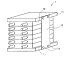
この二次電池は,単体で用いられることもあるが,高電圧・大電流が必要な自動車用等では,複数個の二次電池を組み合わせた電池モジュールが多く使用される。例えば,図1に示すように,扁平状の二次電池をその平面部を重ねて積み重ね,外部を拘束した電池モジュール1がある。この電池モジュール1は,複数個(この図では6個)の二次電池10を向きを揃えて積み重ね,その上下がエンドプレート11によって挟まれている。さらに,エンドプレート11同士がテンションプレート12とリベット13とによって互いに固定されたものである。
This secondary battery may be used alone, but a battery module in which a plurality of secondary batteries are combined is often used for automobiles that require high voltage and large current. For example, as shown in FIG. 1, there is a
一般に,このような電池モジュール1を製造する際には,積み重ねてエンドプレート11で挟んだ二次電池10に対し,積層方向に荷重を加えて拘束している。すなわち,両端のエンドプレート11の外側からプレス機によってプレスし,荷重を加えた状態でテンションプレート12をリベット13で取り付けるのである。これは,前記の文献にもあるように電解液の浸透・拡散を助けるとともに,テンションプレート12による拘束から個々の二次電池10が抜け落ちないことを目的として行われている。以下では,このテンションプレート12を取り付けるときに加えられている荷重を拘束荷重という。
しかしながら,前記した従来の製造方法によって製造された電池モジュールでは,組付け後の時間経過によって,二次電池10にかかる荷重が徐々に低下する,いわゆる「荷重抜け」を起こすおそれがあった。この理由としては,電池セル内の塑性変形要素,例えば,電極板とセパレータシートとの間の微小な隙間やセパレータ自体が有する空隙等が,徐々に圧縮変形されるためであると考えられる。特に,充放電時に発生する熱によってこの塑性変形が促進される。この結果,荷重低下により電極の表面状態が不均一となり,電池の性能が不安定となるおそれがあるという問題点があった。
However, in the battery module manufactured by the above-described conventional manufacturing method, the load applied to the
本発明は,前記した従来の電池モジュールの製造方法が有する問題点を解決するためになされたものである。すなわちその課題とするところは,時間経過や使用による荷重抜けを防止し,長期間にわたって安定した性能を有する電池モジュールを製造できる電池モジュールの製造方法を提供することにある。 The present invention has been made to solve the problems of the conventional battery module manufacturing method described above. That is, an object of the present invention is to provide a battery module manufacturing method capable of manufacturing a battery module having a stable performance over a long period of time by preventing load loss due to passage of time or use.
この課題の解決を目的としてなされた本発明の電池モジュールの製造方法は,平板状電池をエンドプレートで挟んでなる電池モジュールの製造方法であって,平板状電池とエンドプレートとを積層し,その積層体に対して厚さ方向に反復的に荷重を掛け,その後その積層体を拘束するものである。 The battery module manufacturing method of the present invention made for the purpose of solving this problem is a battery module manufacturing method in which a flat battery is sandwiched between end plates, and the flat battery and end plate are laminated, A load is repeatedly applied to the laminated body in the thickness direction, and then the laminated body is restrained.
あるいは本発明の電池モジュールの製造方法は,平板状電池を積み重ねてなる電池モジュールの製造方法であって,複数の平板状電池を積層し,その積層体に対して厚さ方向に反復的に荷重を掛け,その後その積層体を拘束するものであってもよい。 Or the manufacturing method of the battery module of this invention is a manufacturing method of the battery module formed by laminating | stacking a flat battery, Comprising: A several flat battery is laminated | stacked, and load is repeatedly applied to the thickness direction with respect to the laminated body. And then the stack may be restrained.
本発明の電池モジュールの製造方法によれば,平板状電池とエンドプレートとを積層して,あるいは,複数の平板状電池を積層して電池モジュールとする。その際,積層体に対して厚さ方向に反復的に荷重を掛けているので,平板状電池内部の塑性変形要素が効率的に塑性変形される。従って,その後その積層体を拘束した場合に,拘束後に起きる塑性変形は僅かであり,時間経過や使用による荷重抜けが防止される。これにより,長期間にわたって安定した性能を有する電池モジュールを製造できる電池モジュールの製造方法となっている。 According to the battery module manufacturing method of the present invention, a flat battery and an end plate are laminated, or a plurality of flat batteries are laminated to form a battery module. At that time, since the load is repeatedly applied to the laminated body in the thickness direction, the plastic deformation element inside the flat battery is efficiently plastically deformed. Therefore, when the laminate is subsequently restrained, the plastic deformation that occurs after restraint is slight, and load loss due to passage of time or use is prevented. Thereby, it is a manufacturing method of the battery module which can manufacture the battery module which has the performance stable over a long period of time.
さらに本発明では,積層体の拘束を,積層体に荷重を掛けて行うとともに,反復荷重時には,拘束時の荷重より小さい荷重と大きい荷重との間で積層体への荷重を変化させることが望ましい。
このようにすれば,拘束時の荷重より大きい荷重によって塑性変形要素の変形が急速に進行し,小さい荷重に変化させることによって内部の均一化が進行する。従って,短時間で効率的に,安定した性能の電池モジュールを製造することができる。
Furthermore, in the present invention, it is desirable to restrain the laminate by applying a load to the laminate and to change the load on the laminate between a smaller load and a larger load at the time of repeated loading. .
By doing so, the deformation of the plastic deformation element proceeds rapidly by a load larger than the load at the time of restraint, and the internal homogenization proceeds by changing to a smaller load. Therefore, a battery module with stable performance can be manufactured efficiently in a short time.
本発明の電池モジュールの製造方法によれば,時間経過や使用による荷重抜けを防止し,長期間にわたって安定した性能を有する電池モジュールを製造できる。 According to the method for manufacturing a battery module of the present invention, it is possible to manufacture a battery module having a stable performance over a long period of time by preventing load loss due to passage of time or use.
以下,本発明を具体化した最良の形態について,添付図面を参照しつつ詳細に説明する。本形態は,二次電池を複数個積み重ねて構成された電池モジュールを製造する製造方法である。 DESCRIPTION OF THE PREFERRED EMBODIMENTS Hereinafter, the best mode for embodying the present invention will be described in detail with reference to the accompanying drawings. The present embodiment is a manufacturing method for manufacturing a battery module configured by stacking a plurality of secondary batteries.
本形態の製造方法で製造される電池モジュール1は,図1に示すように,扁平形状の二次電池10を複数個積み重ね,エンドプレート11,テンションプレート12,リベット13によって拘束されたものである。ここで,使用される二次電池10としては,缶ケースに封入された缶構造のものでも良いし,ラミネートフィルム外装体に封入されたラミネート構造のものでも良い。エンドプレート11は,鋳鉄等の剛性の高い材料で形成される。テンションプレート12は薄鋼板等で形成され,リベット13はエンドプレート11の側面に取り付けられている。また,リベット13に代えて,ボルト止めするようにしても良い。
As shown in FIG. 1, the
ここで,缶構造の二次電池10を用いた電池モジュール1の場合は,積み重ねて拘束荷重を加えた時に缶ケースの角部同士が押しつけられ,中央部分に十分な荷重が加わらないおそれがある。その点を回避するためと,二次電池10の充放電時の熱を冷却するためを兼ねて,図2に示すように,冷却板14が挿入される。各冷却板14は,二次電池10の平面形状よりやや小さく形成されている。この図に示した電池モジュール1では,複数の冷却板14が,各二次電池10同士の間と,二次電池10と両側のエンドプレート11との間にそれぞれ挿入されている。
Here, in the case of the
次に,本形態の電池モジュール1の製造方法を説明する。まず,各単体の二次電池10を一般的な製造方法で製造する。ここでは,缶構造の二次電池10を用いた電池モジュール1とする。次に,必要個数の二次電池10を間に冷却板14を挟みつつ積み重ね,その両側にエンドプレート11を配置する。次に,この積み重ねた二次電池10とエンドプレート11の全体を,プレス機によって積層方向に加圧する。冷却板14があるので,各二次電池10は図2に示すように変形し,二次電池10の中央部にも十分な荷重が加えられる。なお,この図では分かりやすさのために,二次電池10の変形量を大きく図示しているが,実際の変形量は小さいものである。例えば,元の厚さが15〜20mmの二次電池10の変形量は,缶ケースの角部を含む平面から数mm程度である。
Next, a method for manufacturing the
さらに,テンションプレート12を取り付ける前に,図3に示すように,繰り返し荷重を加える。ここでは,拘束荷重の約2倍の荷重を5回繰り返している。すなわち,まず拘束荷重の約2倍の荷重をかけ,その後荷重を0とすることを4回繰り返す。そして,5回目に拘束荷重の約2倍の荷重をかけた後,拘束荷重まで荷重を下げて保持し,その状態でテンションプレート12をリベット13で取り付ける。これで,電池モジュール1の完成である。繰り返し荷重の1回をそれぞれ10秒程度ずつで行うとよい。
Further, before attaching the
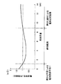
次に,拘束荷重について説明する。拘束荷重には,電池特性を最適なものとするための適切な範囲がある。この関係の例を図4のグラフに示す。この図では,平面が約10cm四方の缶構造の二次電池10を6個積み重ねた電池モジュール1について,拘束荷重と電池特性(ここでは,内部抵抗)との関係を示している。この図に示すように,内部抵抗が所定値以下となるようにするには,拘束荷重を所定範囲内とする必要がある。荷重が小さすぎると,押さえ不足によって電極表面が不均一となり,内部抵抗が大きくなるので好ましくない。また,荷重が大きすぎると,押さえ過大によって電池反応が阻害され,内部抵抗が大きくなるので好ましくない。この例に示した電池モジュール1では,適切な拘束荷重は1〜9kNの範囲内である。
Next, the restraint load will be described. The restraining load has an appropriate range to optimize the battery characteristics. An example of this relationship is shown in the graph of FIG. In this figure, the relationship between the restraining load and the battery characteristics (in this case, the internal resistance) is shown for the
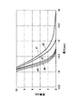
次に,繰り返し荷重の有効性について説明する。本発明者は,ラミネート型の二次電池の1つに繰り返し荷重をかけて,その厚さの変化を調べた。例えば,308型セルと呼ばれる二次電池に10kNまでの荷重を繰り返しかけたところ,その厚さは図5に示すように変化した。荷重をかける前の厚さは約16mmであり,1回目の荷重によってグラフd1のように,14.2mm程度まで圧縮された。その後,荷重を0に戻すと,2回目グラフd2の出発点である約15.1mmまで戻った。このとき,二次電池の弾性要素が元に戻るとともに,塑性変形要素がある程度塑性変形を起こしているためと考えられる。 Next, the effectiveness of repeated loads will be described. The inventor repeatedly applied a load to one of the laminate-type secondary batteries and examined the change in thickness. For example, when a load of up to 10 kN was repeatedly applied to a secondary battery called a 308 type cell, the thickness changed as shown in FIG. The thickness before applying the load was about 16 mm, and the first load was compressed to about 14.2 mm as shown in the graph d1. Thereafter, when the load was returned to 0, it returned to about 15.1 mm, which is the starting point of the second graph d2. At this time, it is considered that the elastic element of the secondary battery is restored and the plastic deformation element undergoes some plastic deformation.
さらに荷重を繰り返すことにより,3回目はグラフd3,4回目はグラフd4,5回目はグラフd5に沿って変化した。この結果から分かるとおり,初めの2〜3回の荷重後は荷重前との差が顕著であり,次第にその差がなくなり,5回目以降では荷重前とほとんど差がなかった。これは,5回の荷重によって塑性変形要素の塑性変形はほぼ完了し,弾性要素のみになったためであると思われる。この結果から,この二次電池では,荷重の繰り返し回数は3回では不足であり,5回より多く繰り返しても効果はほとんど上がらないことが分かった。従って,繰り返し回数は4回以上,望ましくは5回とする。この点において,缶構造の二次電池10でもほぼ同様であった。
Further, by repeating the load, the graph changed along the graph d3 for the third time, the graph d4 for the fourth time, and the graph d5 for the fifth time. As can be seen from the results, the difference from the pre-load was remarkable after the first 2 or 3 loads, and the difference gradually disappeared. This seems to be because the plastic deformation of the plastic deformation element was almost completed by only five loads, and only the elastic element was obtained. From this result, it was found that with this secondary battery, the number of repetitions of the load was insufficient at 3 times, and the effect was hardly improved even when it was repeated more than 5 times. Therefore, the number of repetitions is 4 times or more, preferably 5 times. In this respect, the
以上から,平面が約10cm四方の缶構造の二次電池10を6個積み重ねた電池モジュール1では,適切な繰り返し荷重は以下のようであることがわかった。まず,荷重を約10kNまで上昇させて7〜8秒保持し,その後荷重を0kNに戻す。これを4回繰り返す。5回目に荷重を約10kNまで上昇させた後は約5kNまで戻して保持し,その状態でテンションプレート12をリベット13で取り付ける。このようにして製造した電池モジュール1について所定の環境試験を行った結果,荷重抜けは10%以下となり,良好な拘束特性が得られた。
From the above, it was found that in the
このように,繰り返して荷重をかけることによって,例えば10kNの荷重を長時間にわたってかけ続けるよりも,短時間で効果的に塑性変形が進行する。これにより,二次電池10の内部状態がより良好に均一化される。またこのようにすることで,例えば20kNや30kNといった大きい荷重をかける必要が無く,簡易な設備で実施が可能であるとともに,二次電池自体を破損するおそれもない。
Thus, by repeatedly applying a load, for example, plastic deformation proceeds more effectively in a shorter time than when a load of 10 kN is continuously applied for a long time. Thereby, the internal state of the
以上詳細に説明したように本形態の電池モジュール1の製造方法によれば,繰り返し荷重をかけているので,二次電池10内の塑性変形要素がほぼ完全にキャンセルされ,その後のクリープの発生がない。従って,時間経過や使用による荷重抜けを防止し,長期間にわたって安定した性能を有する電池モジュール1となっている。
As described in detail above, according to the manufacturing method of the
なお,本形態は単なる例示にすぎず,本発明を何ら限定するものではない。したがって本発明は当然に,その要旨を逸脱しない範囲内で種々の改良,変形が可能である。
例えば,繰り返し荷重の大きさ,繰り返し回数,および拘束荷重等は上記の数値に限らず,各電池モジュール1の大きさや構成等に応じて適切なものを選択すればよい。
また,例えば,上記の形態で示した電池モジュール1の構成は1つの例であり,使用する単体の二次電池10のサイズおよびケースの材料や,電池モジュール1に組み込まれる二次電池10の個数等はこれに限るものではない。また,缶構造でなくラミネート構造の二次電池を使用した電池モジュールの場合は,冷却板はなくてもよい。
また,上記の形態では,その製造段階で缶ケースの内部に電極体が圧入された二次電池10を使用している。このため,電極体はケースに実装されるだけで缶ケースから多少の荷重を受けているが,このような二次電池10に限るものではない。
In addition, this form is only a mere illustration and does not limit this invention at all. Therefore, the present invention can naturally be improved and modified in various ways without departing from the gist thereof.
For example, the magnitude of the repeated load, the number of repetitions, the restraint load, and the like are not limited to the above numerical values, and may be selected appropriately according to the size and configuration of each
Further, for example, the configuration of the
Moreover, in said form, the
1 電池モジュール
10 二次電池(平板状電池)
11 エンドプレート
1
11 End plate
Claims (3)
平板状電池とエンドプレートとを積層し,
その積層体に対して厚さ方向に反復的に荷重を掛け,
その後その積層体を拘束することを特徴とする電池モジュールの製造方法。 In a battery module manufacturing method in which a flat battery is sandwiched between end plates,
Laminating a flat battery and end plate,
A load is repeatedly applied to the laminate in the thickness direction,
Thereafter, the laminated body is restrained.
複数の平板状電池を積層し,
その積層体に対して厚さ方向に反復的に荷重を掛け,
その後その積層体を拘束することを特徴とする電池モジュールの製造方法。 In a method for manufacturing a battery module in which flat batteries are stacked,
Laminating multiple flat batteries,
A load is repeatedly applied to the laminate in the thickness direction,
Thereafter, the laminated body is restrained.
積層体の拘束を,積層体に荷重を掛けて行うとともに,
反復荷重時には,拘束時の荷重より小さい荷重と大きい荷重との間で積層体への荷重を変化させることを特徴とする電池モジュールの製造方法。 In the manufacturing method of the battery module according to claim 1 or 2,
The stack is restrained by applying a load to the stack,
A battery module manufacturing method characterized by changing a load on a laminate between a smaller load and a larger load at the time of repetitive loading.
Priority Applications (1)
| Application Number | Priority Date | Filing Date | Title |
|---|---|---|---|
| JP2004155592A JP4581481B2 (en) | 2004-05-26 | 2004-05-26 | Battery module manufacturing method |
Applications Claiming Priority (1)
| Application Number | Priority Date | Filing Date | Title |
|---|---|---|---|
| JP2004155592A JP4581481B2 (en) | 2004-05-26 | 2004-05-26 | Battery module manufacturing method |
Publications (2)
| Publication Number | Publication Date |
|---|---|
| JP2005339929A true JP2005339929A (en) | 2005-12-08 |
| JP4581481B2 JP4581481B2 (en) | 2010-11-17 |
Family
ID=35493260
Family Applications (1)
| Application Number | Title | Priority Date | Filing Date |
|---|---|---|---|
| JP2004155592A Expired - Fee Related JP4581481B2 (en) | 2004-05-26 | 2004-05-26 | Battery module manufacturing method |
Country Status (1)
| Country | Link |
|---|---|
| JP (1) | JP4581481B2 (en) |
Cited By (6)
| Publication number | Priority date | Publication date | Assignee | Title |
|---|---|---|---|---|
| JP2012190620A (en) * | 2011-03-09 | 2012-10-04 | Toyota Motor Corp | Cell restraint device |
| JP2013251060A (en) * | 2012-05-30 | 2013-12-12 | Toyota Motor Corp | Cell system |
| CN109565085A (en) * | 2017-01-24 | 2019-04-02 | 株式会社Lg化学 | For predicting the device of the deformation of battery module |
| US10892514B2 (en) | 2016-12-15 | 2021-01-12 | Toyota Jidosha Kabushiki Kaisha | Method of manufacturing secondary battery stack |
| JP2021039915A (en) * | 2019-09-05 | 2021-03-11 | トヨタ自動車株式会社 | Battery pack |
| US11764393B2 (en) | 2019-02-08 | 2023-09-19 | Toyota Jidosha Kabushiki Kaisha | Pack case, battery pack, and method for manufacturing pack case |
Citations (5)
| Publication number | Priority date | Publication date | Assignee | Title |
|---|---|---|---|---|
| JP2000156211A (en) * | 1998-11-19 | 2000-06-06 | Japan Storage Battery Co Ltd | Battery and battery pack |
| JP2004047161A (en) * | 2002-07-09 | 2004-02-12 | Nissan Motor Co Ltd | Secondary battery and battery pack using same |
| JP2004055346A (en) * | 2002-07-19 | 2004-02-19 | Nissan Motor Co Ltd | Battery pack, composite battery pack, and vehicle mounting it |
| JP2004055169A (en) * | 2002-07-16 | 2004-02-19 | Nissan Motor Co Ltd | Battery pack using layer-built battery |
| JP2005339925A (en) * | 2004-05-26 | 2005-12-08 | Toyota Motor Corp | Inspection method of unit cell and assembly method of battery pack |
-
2004
- 2004-05-26 JP JP2004155592A patent/JP4581481B2/en not_active Expired - Fee Related
Patent Citations (5)
| Publication number | Priority date | Publication date | Assignee | Title |
|---|---|---|---|---|
| JP2000156211A (en) * | 1998-11-19 | 2000-06-06 | Japan Storage Battery Co Ltd | Battery and battery pack |
| JP2004047161A (en) * | 2002-07-09 | 2004-02-12 | Nissan Motor Co Ltd | Secondary battery and battery pack using same |
| JP2004055169A (en) * | 2002-07-16 | 2004-02-19 | Nissan Motor Co Ltd | Battery pack using layer-built battery |
| JP2004055346A (en) * | 2002-07-19 | 2004-02-19 | Nissan Motor Co Ltd | Battery pack, composite battery pack, and vehicle mounting it |
| JP2005339925A (en) * | 2004-05-26 | 2005-12-08 | Toyota Motor Corp | Inspection method of unit cell and assembly method of battery pack |
Cited By (10)
| Publication number | Priority date | Publication date | Assignee | Title |
|---|---|---|---|---|
| JP2012190620A (en) * | 2011-03-09 | 2012-10-04 | Toyota Motor Corp | Cell restraint device |
| JP2013251060A (en) * | 2012-05-30 | 2013-12-12 | Toyota Motor Corp | Cell system |
| US10892514B2 (en) | 2016-12-15 | 2021-01-12 | Toyota Jidosha Kabushiki Kaisha | Method of manufacturing secondary battery stack |
| CN109565085A (en) * | 2017-01-24 | 2019-04-02 | 株式会社Lg化学 | For predicting the device of the deformation of battery module |
| CN109565085B (en) * | 2017-01-24 | 2022-06-03 | 株式会社Lg新能源 | Apparatus for predicting deformation of battery module |
| US11561152B2 (en) | 2017-01-24 | 2023-01-24 | Lg Energy Solution, Ltd. | Apparatus for predicting deformation of battery module |
| US11764393B2 (en) | 2019-02-08 | 2023-09-19 | Toyota Jidosha Kabushiki Kaisha | Pack case, battery pack, and method for manufacturing pack case |
| US11817544B2 (en) | 2019-02-08 | 2023-11-14 | Toyota Jidosha Kabushiki Kaisha | Pack case, battery pack, and method for manufacturing pack case |
| JP2021039915A (en) * | 2019-09-05 | 2021-03-11 | トヨタ自動車株式会社 | Battery pack |
| JP7172921B2 (en) | 2019-09-05 | 2022-11-16 | トヨタ自動車株式会社 | battery pack |
Also Published As
| Publication number | Publication date |
|---|---|
| JP4581481B2 (en) | 2010-11-17 |
Similar Documents
| Publication | Publication Date | Title |
|---|---|---|
| JP2022093710A (en) | Battery grid with varied corrosion resistance | |
| EP1766704B1 (en) | Retaining apparatus for electrochemical generator | |
| DE102008026858B4 (en) | Fuel cell system with a flexible belt system to maintain compression of the fuel cells | |
| EP2251921A2 (en) | Curved battery cell, and a battery pack comprising the same | |
| US10938004B2 (en) | Battery module with stack restraining member | |
| US9166248B2 (en) | Manufacturing method of battery pack | |
| KR20160051647A (en) | Method of manufacturing secondary battery, and secondary battery | |
| JP2007173030A (en) | Battery | |
| WO2011158313A1 (en) | Storage battery device | |
| JP2009099383A (en) | Pressurization structure of laminate | |
| JP2014514694A (en) | Electrochemical cell for storing electrical energy | |
| US10727519B2 (en) | Manufacturing method and apparatus for fuel cell stack | |
| JP4581481B2 (en) | Battery module manufacturing method | |
| JP2017107648A (en) | Battery pack | |
| KR101622437B1 (en) | Press device for jelly roll-secondary battery and Fabricating method of secondary battery using the same | |
| US11342543B2 (en) | Apparatus and method for activating battery cell | |
| KR102389694B1 (en) | Method For Battery Module Having Bead Formed at Frame Structure and Battery Module Using the Same | |
| JP2021503705A (en) | An electrode assembly whose use safety is improved by the structure of the outermost electrode and the material of the current collector, and a lithium ion secondary battery having the electrode assembly. | |
| EP2940756A1 (en) | Battery module | |
| JP2017004923A (en) | Method for manufacturing battery module and locking jig | |
| JP7159965B2 (en) | SECONDARY BATTERY MODULE AND SECONDARY BATTERY MODULE MANUFACTURING METHOD | |
| JP6897411B2 (en) | How to manufacture a secondary battery | |
| EP2779296B1 (en) | Secondary battery including multiple electrode assemblies | |
| JP2619624B2 (en) | Method for manufacturing prismatic alkaline battery | |
| KR20120091184A (en) | Electrochemical cell and method for producing such a cell |
Legal Events
| Date | Code | Title | Description |
|---|---|---|---|
| A621 | Written request for application examination |
Free format text: JAPANESE INTERMEDIATE CODE: A621 Effective date: 20070206 |
|
| A977 | Report on retrieval |
Free format text: JAPANESE INTERMEDIATE CODE: A971007 Effective date: 20080801 |
|
| TRDD | Decision of grant or rejection written | ||
| A01 | Written decision to grant a patent or to grant a registration (utility model) |
Free format text: JAPANESE INTERMEDIATE CODE: A01 Effective date: 20100803 |
|
| A01 | Written decision to grant a patent or to grant a registration (utility model) |
Free format text: JAPANESE INTERMEDIATE CODE: A01 |
|
| A61 | First payment of annual fees (during grant procedure) |
Free format text: JAPANESE INTERMEDIATE CODE: A61 Effective date: 20100816 |
|
| R151 | Written notification of patent or utility model registration |
Ref document number: 4581481 Country of ref document: JP Free format text: JAPANESE INTERMEDIATE CODE: R151 |
|
| FPAY | Renewal fee payment (event date is renewal date of database) |
Free format text: PAYMENT UNTIL: 20130910 Year of fee payment: 3 |
|
| LAPS | Cancellation because of no payment of annual fees |