JP2005334792A - Sieve transfer system - Google Patents
Sieve transfer system Download PDFInfo
- Publication number
- JP2005334792A JP2005334792A JP2004158753A JP2004158753A JP2005334792A JP 2005334792 A JP2005334792 A JP 2005334792A JP 2004158753 A JP2004158753 A JP 2004158753A JP 2004158753 A JP2004158753 A JP 2004158753A JP 2005334792 A JP2005334792 A JP 2005334792A
- Authority
- JP
- Japan
- Prior art keywords
- sieve
- crushing
- storage means
- residue
- transfer
- Prior art date
- Legal status (The legal status is an assumption and is not a legal conclusion. Google has not performed a legal analysis and makes no representation as to the accuracy of the status listed.)
- Pending
Links
Images
Landscapes
- Treatment Of Sludge (AREA)
- Crushing And Pulverization Processes (AREA)
Abstract
【課題】投入された篩渣を確実に破砕すると共に、篩渣の洗浄を効果的に行うことで、篩渣移送の効率化及び衛生化を図り、さらに、設置スペースのコンパクト化、設置コスト及びランニングコストの低減を図ることが可能な篩渣移送システムを提供する。
【解決手段】投入された篩渣を破砕するための破砕手段2と、該破砕手段2により破砕された篩渣を搬送するための搬送手段3と、該搬送手段3により搬送されてきた篩渣の洗浄及び混合撹拌を行う貯留手段4と、該貯留手段4の外部に設けられ、前記貯留手段4内の篩渣を貯留手段4の外に移送するための移送手段5とを備える。
【選択図】図1[PROBLEMS] To improve the efficiency and hygiene of transferring the sieve by reliably crushing the supplied sieve and effectively cleaning the sieve, and further reducing the installation space, reducing the installation cost, A sieve transfer system capable of reducing running costs is provided.
A crushing means 2 for crushing an input sieve, a conveying means 3 for conveying a sieve crushed by the crushing means 2, and a sieve conveyed by the conveying means 3. Storage means 4 for performing washing and mixing and agitation, and transfer means 5 provided outside the storage means 4 for transferring the sieve residue in the storage means 4 to the outside of the storage means 4.
[Selection] Figure 1
Description
本発明は、特に、下水ポンプ場や下水処理場等で掻揚げられた篩渣を移送するのに好適な篩渣移送システムに関する。 In particular, the present invention relates to a sieve transfer system suitable for transferring a sieve scraped up at a sewage pump station or a sewage treatment plant.
下水ポンプ場や下水処理場等においては、流入原水中のプラスチック、髪の毛、木の葉、木片、スカム等のごみを予め除塵機等で除去したうえで処理工程に送っている。前記除塵機等により掻揚げられた分離物は篩渣と呼ばれている。 In sewage pump stations and sewage treatment plants, wastes such as plastics, hair, leaves, wooden pieces, and scum in inflow raw water are removed in advance with a dust remover and sent to the treatment process. The separated material swept up by the dust remover or the like is called sieve residue.
従来、前記除塵機等により分離された篩渣は、篩渣貯留設備のある場所までケースコンベヤやベルトコンベヤ等により水平方向及び垂直方向に搬送されていたが、コンベヤ設置のために広いスペースを必要とするうえ、水分がコンベヤの周囲に飛散したり、コンベヤが密閉困難なため悪臭が外部飛散するという問題がある。 Conventionally, the sieves separated by the dust remover etc. have been transported horizontally and vertically by case conveyors, belt conveyors, etc. to the place where the sieve storage facilities are located, but a large space is required for conveyor installation. In addition, there are problems that moisture scatters around the conveyor and that the odor is scattered outside because the conveyor is difficult to seal.
これに対し、例えば、特開2001−187399号公報(特許文献1)には、
下水処理場等にて回収されたスクリーン渣(前記「篩渣」と同意)を処理槽へ搬送する流水トラフと、スクリーン渣を破砕洗浄する処理槽と、該処理槽の外に配設された移送ポンプ、移送配管及びスクリーン渣分離機とから構成されるスクリーン渣の処理システムが記載されている。ここで、前記処理槽は、一体構造の槽内に第1次洗浄部、破砕部及び第2次洗浄部を設け、下水処理場から回収されたスクリーン渣を受け入れてスクリーン渣の破砕と洗浄を行うものである。なお、前記特許文献1には、前記破砕部の脇にディスク式スクリーンを併設して、これにより第1次洗浄部内に投入された篩渣を、よりスムーズに破砕部まで導くようにした実施例も示されている。
On the other hand, for example, JP 2001-187399 A (Patent Document 1)
A flowing water trough for transporting the screen residue collected at a sewage treatment plant etc. (agreement with the “sieve residue”) to the treatment tank, a treatment tank for crushing and washing the screen residue, and the outside of the treatment tank A screen residue processing system including a transfer pump, a transfer pipe, and a screen residue separator is described. Here, the processing tank is provided with a primary cleaning section, a crushing section, and a secondary cleaning section in an integrated tank, and receives the screen residue recovered from the sewage treatment plant to crush and clean the screen residue. Is what you do. In Patent Document 1, a disc type screen is provided beside the crushing part, and thereby the sieve put in the primary cleaning part is more smoothly guided to the crushing part. Is also shown.
前記特許文献1では、このような構成とすることで、下水処理場等にて回収されたスクリーン渣を、コンパクトな設備により確実に破砕洗浄して、さらに、衛生的に処理することができるとしている。
しかし、上記特許文献1に記載のスクリーン渣の処理システムでは、以下のような問題がある。 However, the screen residue processing system described in Patent Document 1 has the following problems.
(1)前記処理システムの処理槽においては、処理槽を略二分する中央部に破砕部を垂直に設置している。そのため、流水トラフから処理槽の第1次洗浄部に搬入されたスクリーン渣は、スムーズに破砕部の羽口まで到達することができず、スクリーン渣が処理槽内で団子状の塊となって沈んだり、或いは、浮いたままの状態になりやすく、スクリーン渣の破砕処理が効率的に行われない。これに対し、前記特許文献1には、第1次洗浄部の底部に給水ノズルを設け、ここから噴射される洗浄水によって、スクリーン渣の沈澱を防ぎ、さらに、スクリーン渣を破砕部に向けて移送する方法が示されている。しかし、前記処理槽底部に設けられた給水ノズルから洗浄水を噴射させる方法では、底部に沈澱したスクリーン渣に対してはある程度の移送効果は認められるが、浮いた状態のスクリーン渣に対する移送効果は極めて低く、破砕効果の向上には疑問がある。 (1) In the processing tank of the said processing system, the crushing part is installed vertically in the center part which bisects a processing tank. Therefore, the screen residue carried from the running water trough to the primary cleaning part of the treatment tank cannot smoothly reach the tuyere of the crushing part, and the screen residue becomes a dumpling-like lump in the treatment tank. It tends to sink or remain floating, and the screen residue is not efficiently crushed. On the other hand, in Patent Document 1, a water supply nozzle is provided at the bottom of the primary cleaning unit, and the washing water sprayed from the nozzle prevents sedimentation of the screen residue, and further directs the screen residue toward the crushing unit. The method of transport is shown. However, in the method of injecting the washing water from the water supply nozzle provided at the bottom of the treatment tank, a certain amount of transfer effect is recognized for the screen residue settled on the bottom, but the transfer effect for the screen residue in the floating state is It is extremely low and there are doubts about improving the crushing effect.
(2)前記処理システムの処理槽においては、破砕部の羽口までスクリーン渣を移送する推進力を、上述のように、水の流れにだけに依存しているので、スクリーン渣を破砕部の羽口まで送り込むという点において効率が悪い。また、前記特許文献1には、前記破砕部の脇にディスク式スクリーンを併設して、これにより第1次洗浄部内に投入された篩渣を、よりスムーズに破砕部まで導くようにした実施例も示されているが、スクリーン渣を強制的に破砕部の羽口に送込むまでの能力はなく、逆に機械装置部分が増えることにより当該部分の故障や維持管理要素が増える等の問題点が生じている。 (2) In the treatment tank of the treatment system, the propulsive force for transferring the screen residue to the tuyeres of the crushing unit depends only on the flow of water as described above. Inefficient in terms of sending to the tuyere. Further, in Patent Document 1, a disk-type screen is provided beside the crushing part, and thereby the sieve put in the primary cleaning part is more smoothly guided to the crushing part. However, there is no ability to force the screen residue to be sent to the tuyeres of the crushing part. Has occurred.
(3))前記処理システムにおいては、スクリーン渣の破砕及び洗浄を一体構造の処理槽内で行っているため、処理槽内の水がスクリーン渣と共に搬入された糞塊等の有機物に汚染されやすく、処理槽から移送されるスクリーン渣の洗浄効果が十分ではない。 (3) In the above processing system, since the screen residue is crushed and washed in the integrated processing tank, the water in the processing tank is likely to be contaminated by organic matter such as feces that are carried along with the screen residue. The cleaning effect of the screen residue transferred from the treatment tank is not sufficient.
(4)前記処理システムにおいては、処理槽を第1次洗浄部、破砕部、第2次洗浄部に区分する必要上、槽が大型化して広い設置スペースを必要とし、例えば、小規模の沈砂池等への設置が困難である。 (4) In the above processing system, it is necessary to divide the processing tank into a primary cleaning section, a crushing section, and a secondary cleaning section, and the tank is enlarged and requires a large installation space. It is difficult to install in a pond.
本発明は、上記課題を解決するためになされたもので、投入された篩渣を確実に破砕すると共に、篩渣の洗浄を効果的に行うことで、篩渣移送の効率化及び衛生化を図り、さらに、設置スペースのコンパクト化、設置コスト及びランニングコストの低減を図ることが可能な篩渣移送システムを提供することを目的とする。 The present invention has been made in order to solve the above-mentioned problems, and it is possible to improve the efficiency and sanitization of the transfer of the sieve by reliably crushing the supplied sieve and effectively cleaning the sieve. Furthermore, it aims at providing the sieve transfer system which can aim at size reduction of installation space, reduction of installation cost, and running cost.
上記の課題は次の発明により解決される。
[1]投入された篩渣を破砕するための破砕手段と、
該破砕手段により破砕された篩渣を搬送するための搬送手段と、
該搬送手段により搬送されてきた篩渣の洗浄及び混合撹拌を行う貯留手段と、
該貯留手段の外部に設けられ、前記貯留手段内の篩渣を貯留手段の外に移送するための移送手段とを備えたことを特徴とする篩渣移送システム。
[2]上記[1]において、搬送手段が、篩渣を洗浄するための機能を備えていることを特徴とする篩渣移送システム。
[3]上記[1]又は[2]において、移送手段が、無閉塞ポンプであることを特徴とする篩渣移送システム。
The above problems are solved by the following invention.
[1] Crushing means for crushing the charged sieve,
Conveying means for conveying the sieve crushed by the crushing means;
A storage means for washing and mixing and stirring the sieve transported by the transport means;
A sieve transfer system comprising a transfer means provided outside the storage means for transferring the sieve residue in the storage means to the outside of the storage means.
[2] The sieve transfer system according to [1], wherein the conveying means has a function for cleaning the sieve.
[3] The sieve transfer system according to [1] or [2], wherein the transfer means is a non-occlusive pump.
本発明によれば、投入された篩渣を確実に破砕すると共に、篩渣の洗浄を効果的に行うことで、篩渣移送の効率化及び衛生化を図り、さらに、システムの設置スペースのコンパクト化、設置コスト及びランニングコストの低減を図ることが可能な篩渣移送システムが提供される。 According to the present invention, the introduced sieve is reliably crushed and the sieve is effectively washed, thereby improving the efficiency and sanitization of the transfer of the sieve, and further reducing the installation space of the system. A sieve transfer system that can reduce the cost, installation cost, and running cost is provided.
以下、本発明を実施するための最良の形態の一例を説明する。 Hereinafter, an example of the best mode for carrying out the present invention will be described.
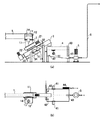
図1は、本発明に係る篩渣移送システムの一実施形態を示す概略構成図である。図1において、(a)図は側面図、(b)図は平面図である。 FIG. 1 is a schematic configuration diagram showing an embodiment of a sieve transfer system according to the present invention. 1A is a side view, and FIG. 1B is a plan view.
下水ポンプ場や下水処理場等において除塵機等で分離除去された篩渣は、図1に示すように、篩渣供給手段1によって、破砕手段2内に投入される。この破砕手段2では、投入された篩渣の破砕を行う。前記破砕手段2で破砕された篩渣は、搬送手段3により搬送されて、貯留手段4に投入される。前記貯留手段4に投入された篩渣は、貯留手段4内で洗浄及び混合撹拌される。前記貯留手段4内で洗浄された篩渣は、貯留手段4内の水と混合撹拌されることでスラリー化される。前記スラリー化された貯留手段4内の篩渣は、貯留手段4に設けられた篩渣排出口から、前記貯留手段4の外部に設けられた移送手段5により排出される。前記移送手段5により排出されたスラリー化された篩渣は、前記移送手段5の吐出側に接続された配管6内を通して、例えば、篩渣の貯留設備等に移送される。
The sieve residue separated and removed by a dust remover or the like at a sewage pumping station, a sewage treatment plant or the like is introduced into the crushing means 2 by the sieve supply means 1 as shown in FIG. In this crushing means 2, the supplied sieve residue is crushed. The sieve residue crushed by the crushing means 2 is conveyed by the conveying means 3 and put into the storage means 4. The sieve cake put into the storage means 4 is washed and mixed and stirred in the storage means 4. The sieve residue washed in the storage means 4 is mixed with agitation with water in the storage means 4 to be slurried. The slurry in the slurry storage means 4 is discharged from a sieve discharge port provided in the storage means 4 by a
以下、前記篩渣移送システムの各構成についてさらに詳しく説明する。 Hereinafter, each configuration of the sieve transfer system will be described in more detail.
前記破砕手段2の前段に設けられる篩渣供給手段1としては、流水トラフを用いることができる。流水トラフは、篩渣を飛散させることなく搬送することが可能であるので、衛生的に篩渣を移送するのに優れている。 A running water trough can be used as the sieve supply means 1 provided in the preceding stage of the crushing means 2. Since the flowing water trough can be transported without splashing the sieve residue, it is excellent for hygienically transferring the sieve residue.
前記篩渣供給手段1として、流水トラフを用いる場合は、流水トラフ1の出口、つまり、破砕手段2との接続部近傍に越流堰11を設け、越流水は、越流ボックス12で受けた後、バイパスライン13を通して、篩渣を分離除去する除塵機(図示せず)の上流側に導くようにすることが好ましい。これにより、流水トラフ1の後段に設けられる破砕手段2が故障し、篩渣の処理ができなくなり、流水が破砕手段2を通過できずに水位が上昇した場合でも、流水トラフ1から篩渣が溢れることが無く、篩渣が溢れ飛散することによる環境汚染を防止できる。なお、前記流水トラフ1の出口の越流堰11近傍には液面計14を設けるようにしても良い。これにより、破砕手段2が篩渣によって閉塞した場合、流水トラフ1からの流水が破砕手段2を全量通過できず、越流ボックス12の水位が上昇するので、破砕手段2の不具合を自動的に検知することが可能となる。
When a running water trough is used as the sieve supply means 1, an
前記破砕手段2としては、例えば、2軸回転式破砕機を用いることができる。より具体的には、複数枚のディスク状のカッターを回転軸上に固定した2組の破砕ユニット22を、この破砕ユニット22のディスク状カッター同士が互いに重なり合うように配設し、駆動装置21で駆動するように構成したディスク式破砕機を用いることができる。
As the crushing means 2, for example, a biaxial rotary crusher can be used. More specifically, two sets of crushing
本発明においては、篩渣供給手段1によって破砕手段2内に投入された篩渣は、この破砕手段2で確実に破砕される。そのため、従来技術において見られたような、篩渣の塊が底に沈み破砕されずに残留したり、水面に浮上した発泡スチロールやボール等の軽い篩渣が破砕されずに滞留するようなことが無く、すべての篩渣が確実に破砕される。 In the present invention, the sieve put in the crushing means 2 by the sieve supply means 1 is reliably crushed by the crushing means 2. Therefore, as seen in the prior art, the lump of the sieve residue may sink to the bottom and remain without being crushed, or the light sieve residue such as polystyrene foam or balls floating on the water surface may remain without being crushed. And all sieve residue is reliably crushed.
前記搬送手段3としては、例えば、スクリューコンベア3を用いることができる。前記スクリューコンベア3としては、センターシャフトの周りにらせん状のスクリュー31を設けたものや、センターシャフトを有しないリボンタイプのものを用いることができる。前記スクリュー31は、駆動装置36により駆動される。
As the transport means 3, for example, a screw conveyor 3 can be used. As the screw conveyor 3, one provided with a
ここで、前記搬送手段3には、該搬送手段3内を通過する篩渣を洗浄するための機能を備えることが好ましい。前記搬送手段3で篩渣を搬送する途中で、1次洗浄としての篩渣の洗浄を行うことで、後段の貯留手段4に投入される篩渣の清浄度をより向上させることができ、衛生性がより改善される。これにより、後段の貯留手段4内での篩渣の洗浄及び混合撹拌をより効率的に行うことが可能となる。さらに、前記1次洗浄により、篩渣中の糞塊等の有機物を除去できるので、篩渣の大幅な減容化も図ることが可能となる。 Here, it is preferable that the transport unit 3 has a function for cleaning the sieve passing through the transport unit 3. By cleaning the sieve as the primary cleaning during the transfer of the sieve by the transfer means 3, the cleanliness of the sieve put into the storage means 4 in the subsequent stage can be further improved, and hygiene Sex is improved more. This makes it possible to more efficiently perform cleaning and mixing and stirring of the sieve residue in the storage means 4 at the subsequent stage. Furthermore, since the organic matter such as feces in the sieve can be removed by the primary cleaning, the volume of the sieve can be greatly reduced.
前記篩渣を洗浄するための機能としては、例えば、スクリューコンベアを用いる場合、スクリューコンベア3のトラフの内側に洗浄ノズル32を設け、そこから搬送途中の篩渣に洗浄水を噴射することができるようにすることで行うことができる。ここで、前記洗浄ノズル32は、篩渣の洗浄をより効果的に行うために、洗浄水の噴射方向がそれぞれ異なるように複数本設け、スクリューコンベア3に噴射することが好ましい。前記洗浄水は、洗浄ノズル32に洗浄水を供給するための洗浄水供給配管の途中に設けられた洗浄水調整弁により、その流量及び圧力が調整するようにしてもよい。なお、前記搬送手段3の下方には、排水スクリーン33を介して排水パン34が設置されており、篩渣中の水分及び洗浄排水が、前記排水パン34に設けられた排水管35から排出され、沈砂池或いは排水処理施設等に送られる。
As a function for cleaning the sieve, for example, when a screw conveyor is used, a cleaning
また、前記搬送手段3には、脱水機能を持たせることも好ましい。これにより、破砕された篩渣に含まれる有機分を脱離液と共に排出されるので、後段の貯留手段4に供給される篩渣を、さらに衛生的とすることが可能となる。 Further, it is preferable that the transport means 3 has a dehydrating function. Thereby, since the organic content contained in the crushed sieve is discharged together with the desorbed liquid, the sieve supplied to the storage means 4 in the subsequent stage can be made more sanitary.
なお、前記脱水機能を持たせる方法としては、例えば、篩渣排出口が上方になるように搬送手段3を傾斜させる方法、篩渣排出口近傍の断面積を暫減させ口径を絞る方法、或いは、篩渣の排出部の管形をS字形または逆U字形に持ち上げることによって排出させる方法等を用いることができる。さらに、スクリューコンベアを使用する場合、スクリューのピッチを排出口に近い方を密にすることによっても、脱水機能を持たせることが可能となる。 In addition, as a method of giving the dehydration function, for example, a method of inclining the conveying means 3 so that the sieve discharge port is upward, a method of reducing the cross-sectional area in the vicinity of the sieve discharge port and narrowing the diameter, or A method of discharging by lifting the tube shape of the discharge part of the sieve residue into an S shape or an inverted U shape can be used. Furthermore, when a screw conveyor is used, it is possible to provide a dehydrating function by making the pitch of the screw closer to the discharge port.
前記貯留手段4では、前記搬送手段3によって搬送されてきた篩渣の洗浄及び混合撹拌を行う。貯留手段4には、槽内の篩渣の洗浄及び混合撹拌を効率的に行うために、撹拌機41又は水噴射ノズル42、又は、撹拌機41及び水噴射ノズル42の両方を備えることが好ましい。また、前記貯留手段4には、液面計43及び排水口44を設けて、貯留手段4内の水量が所定量を超える場合には、前期排水口44から排水して、貯留手段4からの篩渣の溢れ(オーバーフロー)を防止することが好ましい。なお、前記排水口からの排水には、破砕された微細な篩渣やスクリューコンベア3で洗浄されずに残った有機分が含まれる。そのため、前記排水口からの排水は、例えば、下水ポンプ場や下水処理場等に設けられた沈砂池等に戻すようにすることが好ましい。
In the storage unit 4, the sieve transported by the transport unit 3 is washed and mixed and stirred. The storage means 4 is preferably provided with a
また、前記貯留手段4の槽形状としては、図1に示すように、篩渣の排出を効率的に行うために、矩形の槽の底部に傾斜を設け、槽の最深部に貯留手段4から篩渣を排出するための篩渣排出口45を設けるようにすることが好ましい。この場合、前記搬送手段3からの篩渣の投入位置、及び、前記撹拌機41と水噴射ノズル42の設置位置は、前記篩渣排出口45の上流側に設けることが好ましい。これにより、貯留手段4内での篩渣の洗浄及び混合撹拌効果をより高めることができ、篩渣が貯留手段4内でスラリー状態となり、貯留手段4内からの篩渣の排出をより効果的に行うことが可能となる。
In addition, as shown in FIG. 1, the storage means 4 has a tank shape that is inclined at the bottom of the rectangular tank so that the sieve can be efficiently discharged. It is preferable to provide a
なお、前記貯留手段4の形状としては、図1に示す矩形に限られるものではなく、円筒形状とすることもできる。この場合、例えば、円筒形の槽の底部を逆円錐形状として、その頂点部分(最深部)に篩渣の排出口45を設けるようにしてもよい。また、前記撹拌機41又は水噴射ノズル42、又は、撹拌機41及び水噴射ノズル42の両方を、槽内に渦流れができるように水流方向を調整することが好ましい。これにより、貯留手段4内での篩渣の洗浄及び混合撹拌効果をさらに高めることが可能となる。
The shape of the storage means 4 is not limited to the rectangle shown in FIG. 1 and may be a cylindrical shape. In this case, for example, the bottom of the cylindrical tank may have an inverted conical shape, and a
本発明においては、前記破砕手段2により破砕された篩渣のみが貯留手段4に投入されるので、貯留手段4内での篩渣の洗浄及び混合撹拌効果に優れ、篩渣の衛生性を大幅に向上させることができる。さらに、篩渣に含まれる有機分を効率よく除去できるので、篩渣の大幅な減溶化を図ることができる。これらの効果は、前記搬送手段3に篩渣を洗浄するための機能を持たせることで、さらに向上させることができる。このように、貯留手段4内での篩渣の洗浄及び混合撹拌効果を向上させることが可能となるので、貯留手段4の容量を大幅に小型化することが可能となり、本発明に係る篩渣移送システムの設置スペースを大幅に小型化することが可能となる。 In the present invention, only the sieve residue crushed by the crushing means 2 is put into the storage means 4, so that the cleaning effect of the sieve in the storage means 4 and the mixing and stirring effect are excellent, and the hygiene of the sieve is greatly improved. Can be improved. Furthermore, since organic components contained in the sieve can be efficiently removed, the sieve can be greatly reduced in solubility. These effects can be further improved by providing the conveying means 3 with a function for washing the sieve residue. As described above, the effect of washing and mixing and stirring the sieve in the storage means 4 can be improved, so that the capacity of the storage means 4 can be greatly reduced, and the sieve according to the present invention. The installation space of the transfer system can be greatly reduced.
また、前記配管6の下流側に設置される篩渣の貯留設備(図示せず)で、篩渣から分離された排水は、前記貯留手段4内に戻すようにして、何サイクルか循環使用するようにしても良い。これにより、節水効果をもたせることができる。
In addition, the wastewater separated from the sieve is returned to the storage means 4 by a sieve storage facility (not shown) installed on the downstream side of the
前記移送手段5は、前記貯留手段4の外部に設けられ、貯留手段4内の篩渣を貯留手段の外に移送するものである。 The transfer means 5 is provided outside the storage means 4 and transfers the sieve residue in the storage means 4 to the outside of the storage means.
ここで、前記移送手段5としては、ポンプ、特に、無閉塞型のポンプを用いることが好ましい。 Here, as the transfer means 5, it is preferable to use a pump, in particular, a non-occlusive pump.
なお、前記移送手段5を貯留手段4の外部に設けることで、メンテナンス性の向上を図ることができる。 In addition, by providing the transfer means 5 outside the storage means 4, it is possible to improve maintainability.
前記移送手段5により、貯留手段4に設けた篩渣の排出口45から吸引されたスラリー状態の篩渣は、移送手段5の吐出側に接続された配管6内を通して、例えば、篩渣の貯留設備等に移送される。前記配管6は、パイプ状の配管を用いることで、搬送途中での篩渣の飛散を防止でき、より衛生的に篩渣を搬送することが可能となる。
The slurry in the slurry state sucked by the transfer means 5 from the
なお、前記移送手段5の運転に係るON/OFF制御を、前記貯留手段4に設けた液面計43からの水位信号で行うようにしてもよい。例えば、前記液面計43からの水位信号が所定のレベル(Highレベル)に達した場合に移送手段5の運転を開始(ON)し、前記液面計43からの水位信号が所定のレベル(Lowレベル)に達した場合に移送手段5の運転を停止(OFF)するようにすることが好ましい。
The ON / OFF control relating to the operation of the transfer means 5 may be performed by a water level signal from a
1 篩渣供給手段(流水トラフ)
11 越流堰
12 越流ボックス
13 バイパスライン
14 液面計
2 破砕手段
21 駆動装置
22 破砕ユニット
3 搬送手段(スクリューコンベア)
31 スクリュー
32 洗浄ノズル
33 排水スクリーン
34 排水パン
35 排水管
36 駆動装置
4 貯留手段
41 撹拌機
42 水噴射ノズル
43 液面計
44 排水口
45 篩渣排出口
5 移送手段
6 配管
1 Sieve supply means (running trough)
DESCRIPTION OF
31
Claims (3)
該破砕手段により破砕された篩渣を搬送するための搬送手段と、
該搬送手段により搬送されてきた篩渣の洗浄及び攪拌を行う貯留手段と、
該貯留手段の外部に設けられ、前記貯留手段内の篩渣を貯留手段の外に移送するための移送手段とを備えたことを特徴とする篩渣移送システム。 Crushing means for crushing the charged sieve,
Conveying means for conveying the sieve crushed by the crushing means;
A storage means for cleaning and stirring the sieve that has been conveyed by the conveying means;
A sieve transfer system comprising a transfer means provided outside the storage means for transferring the sieve residue in the storage means to the outside of the storage means.
Priority Applications (1)
| Application Number | Priority Date | Filing Date | Title |
|---|---|---|---|
| JP2004158753A JP2005334792A (en) | 2004-05-28 | 2004-05-28 | Sieve transfer system |
Applications Claiming Priority (1)
| Application Number | Priority Date | Filing Date | Title |
|---|---|---|---|
| JP2004158753A JP2005334792A (en) | 2004-05-28 | 2004-05-28 | Sieve transfer system |
Publications (1)
| Publication Number | Publication Date |
|---|---|
| JP2005334792A true JP2005334792A (en) | 2005-12-08 |
Family
ID=35488927
Family Applications (1)
| Application Number | Title | Priority Date | Filing Date |
|---|---|---|---|
| JP2004158753A Pending JP2005334792A (en) | 2004-05-28 | 2004-05-28 | Sieve transfer system |
Country Status (1)
| Country | Link |
|---|---|
| JP (1) | JP2005334792A (en) |
Cited By (4)
| Publication number | Priority date | Publication date | Assignee | Title |
|---|---|---|---|---|
| JP2010279859A (en) * | 2009-06-02 | 2010-12-16 | Asahi Tec Environmental Solutions Corp | Fluid transfer device for sewage treatment |
| CN106081516A (en) * | 2016-08-25 | 2016-11-09 | 怀宁县环能机制炭有限公司 | A kind of pulverizing conveying equipment coordinating stalk granulator to use |
| CN106423453A (en) * | 2016-10-09 | 2017-02-22 | 芜湖瑞德机械科技有限公司 | Raw material crushing and mixing all-in-one machine suitable for paint machining and operation method thereof |
| CN108751632A (en) * | 2018-05-22 | 2018-11-06 | 四川深蓝环保科技有限公司 | A kind of processing system and method for oily sludge |
-
2004
- 2004-05-28 JP JP2004158753A patent/JP2005334792A/en active Pending
Cited By (5)
| Publication number | Priority date | Publication date | Assignee | Title |
|---|---|---|---|---|
| JP2010279859A (en) * | 2009-06-02 | 2010-12-16 | Asahi Tec Environmental Solutions Corp | Fluid transfer device for sewage treatment |
| CN106081516A (en) * | 2016-08-25 | 2016-11-09 | 怀宁县环能机制炭有限公司 | A kind of pulverizing conveying equipment coordinating stalk granulator to use |
| CN106081516B (en) * | 2016-08-25 | 2019-01-22 | 怀宁县环能机制炭有限公司 | A kind of crushing conveying equipment that cooperation stalk granulator uses |
| CN106423453A (en) * | 2016-10-09 | 2017-02-22 | 芜湖瑞德机械科技有限公司 | Raw material crushing and mixing all-in-one machine suitable for paint machining and operation method thereof |
| CN108751632A (en) * | 2018-05-22 | 2018-11-06 | 四川深蓝环保科技有限公司 | A kind of processing system and method for oily sludge |
Similar Documents
| Publication | Publication Date | Title |
|---|---|---|
| KR101804226B1 (en) | Dehydration dry equipment for sludge handling | |
| EP3539669B1 (en) | Apparatus and method for cleaning contaminated materials | |
| CN107053535B (en) | Integrated device for crushing, cleaning and separating impurities and sinking and floating materials from plastics | |
| KR101656493B1 (en) | Sewage disposal machine | |
| JP2005334792A (en) | Sieve transfer system | |
| JP2005334793A (en) | Sieve transfer system | |
| JP2020081917A (en) | Scum conveyance device | |
| JPS6233564A (en) | Method and apparatus for treating contaminated grit | |
| JP2006095401A (en) | Screen residue treatment device | |
| KR20030078574A (en) | the recycling sand a sorter | |
| JP2004141818A (en) | Apparatus for transferring solid substance from grit tank by fluid | |
| JP4016131B2 (en) | Rice washing equipment | |
| KR101352690B1 (en) | Sewage pre-screened with circular grit chamber | |
| KR200179035Y1 (en) | Disposal device of waste water with oil | |
| JP2001187399A (en) | Screen residue processing system | |
| KR100668478B1 (en) | Five. Wastewater Sand Washer | |
| KR20190018884A (en) | Apparatus for removing sediment of anaerobic disgester | |
| JP7406523B2 (en) | Sand cleaning equipment | |
| JPH11300400A (en) | Mobile sludge dehydrating car | |
| KR101008768B1 (en) | Sedimentation dehydrator with agitation and separator | |
| JP2010234217A (en) | Powder processing system and powder processing method | |
| JP2005342545A (en) | Sediment separation and transfer device | |
| JP3396684B2 (en) | Cleaning treatment method and apparatus | |
| JP2006095413A (en) | Sand separation and cleaning equipment | |
| JP2023131456A (en) | Processed material transport device, method of operating the processed material transport device, and control program for the processed material transport device |
Legal Events
| Date | Code | Title | Description |
|---|---|---|---|
| A621 | Written request for application examination |
Free format text: JAPANESE INTERMEDIATE CODE: A621 Effective date: 20060807 |
|
| A977 | Report on retrieval |
Free format text: JAPANESE INTERMEDIATE CODE: A971007 Effective date: 20090715 |
|
| A131 | Notification of reasons for refusal |
Free format text: JAPANESE INTERMEDIATE CODE: A131 Effective date: 20090811 |
|
| A02 | Decision of refusal |
Free format text: JAPANESE INTERMEDIATE CODE: A02 Effective date: 20100126 |