JP2005333322A - Bobbin-integrated magnesium diaphragm, its manufacturing method, and speaker device using the same - Google Patents
Bobbin-integrated magnesium diaphragm, its manufacturing method, and speaker device using the same Download PDFInfo
- Publication number
- JP2005333322A JP2005333322A JP2004148873A JP2004148873A JP2005333322A JP 2005333322 A JP2005333322 A JP 2005333322A JP 2004148873 A JP2004148873 A JP 2004148873A JP 2004148873 A JP2004148873 A JP 2004148873A JP 2005333322 A JP2005333322 A JP 2005333322A
- Authority
- JP
- Japan
- Prior art keywords
- diaphragm
- magnesium
- bobbin
- rolling
- speaker
- Prior art date
- Legal status (The legal status is an assumption and is not a legal conclusion. Google has not performed a legal analysis and makes no representation as to the accuracy of the status listed.)
- Pending
Links
- FYYHWMGAXLPEAU-UHFFFAOYSA-N Magnesium Chemical compound [Mg] FYYHWMGAXLPEAU-UHFFFAOYSA-N 0.000 title claims abstract description 218
- 229910052749 magnesium Inorganic materials 0.000 title claims abstract description 191
- 239000011777 magnesium Substances 0.000 title claims abstract description 191
- 238000004519 manufacturing process Methods 0.000 title claims abstract description 22
- 238000005096 rolling process Methods 0.000 claims abstract description 88
- 238000010438 heat treatment Methods 0.000 claims abstract description 11
- 238000000034 method Methods 0.000 claims description 29
- 239000000758 substrate Substances 0.000 claims description 22
- 230000007423 decrease Effects 0.000 claims description 3
- 239000000463 material Substances 0.000 abstract description 62
- RTAQQCXQSZGOHL-UHFFFAOYSA-N Titanium Chemical compound [Ti] RTAQQCXQSZGOHL-UHFFFAOYSA-N 0.000 description 40
- 239000010936 titanium Substances 0.000 description 40
- 229910052719 titanium Inorganic materials 0.000 description 40
- 229910052782 aluminium Inorganic materials 0.000 description 32
- XAGFODPZIPBFFR-UHFFFAOYSA-N aluminium Chemical compound [Al] XAGFODPZIPBFFR-UHFFFAOYSA-N 0.000 description 32
- 230000035945 sensitivity Effects 0.000 description 24
- 230000002093 peripheral effect Effects 0.000 description 12
- 239000000853 adhesive Substances 0.000 description 9
- 230000001070 adhesive effect Effects 0.000 description 9
- 230000005484 gravity Effects 0.000 description 7
- 230000008569 process Effects 0.000 description 6
- 230000000694 effects Effects 0.000 description 5
- 229910052751 metal Inorganic materials 0.000 description 5
- 239000002184 metal Substances 0.000 description 5
- 238000000465 moulding Methods 0.000 description 4
- 239000011347 resin Substances 0.000 description 4
- 229920005989 resin Polymers 0.000 description 4
- 239000012855 volatile organic compound Substances 0.000 description 4
- 230000007547 defect Effects 0.000 description 3
- 230000017525 heat dissipation Effects 0.000 description 3
- 238000005304 joining Methods 0.000 description 3
- 230000007246 mechanism Effects 0.000 description 3
- 230000003647 oxidation Effects 0.000 description 3
- 238000007254 oxidation reaction Methods 0.000 description 3
- 101150042817 NFS1 gene Proteins 0.000 description 2
- 101100126298 Rickettsia conorii (strain ATCC VR-613 / Malish 7) iscS gene Proteins 0.000 description 2
- 101150114492 SPL1 gene Proteins 0.000 description 2
- 101150056353 SPL2 gene Proteins 0.000 description 2
- 101150090744 SPL3 gene Proteins 0.000 description 2
- 230000008859 change Effects 0.000 description 2
- 239000013078 crystal Substances 0.000 description 2
- 238000005520 cutting process Methods 0.000 description 2
- 230000007613 environmental effect Effects 0.000 description 2
- 238000005259 measurement Methods 0.000 description 2
- 239000007769 metal material Substances 0.000 description 2
- 150000002739 metals Chemical class 0.000 description 2
- 230000000704 physical effect Effects 0.000 description 2
- 238000000746 purification Methods 0.000 description 2
- 230000002159 abnormal effect Effects 0.000 description 1
- 230000009471 action Effects 0.000 description 1
- 230000008901 benefit Effects 0.000 description 1
- VYQRBKCKQCRYEE-UHFFFAOYSA-N ctk1a7239 Chemical compound C12=CC=CC=C2N2CC=CC3=NC=CC1=C32 VYQRBKCKQCRYEE-UHFFFAOYSA-N 0.000 description 1
- 229910003460 diamond Inorganic materials 0.000 description 1
- 239000010432 diamond Substances 0.000 description 1
- 229910010272 inorganic material Inorganic materials 0.000 description 1
- 239000011147 inorganic material Substances 0.000 description 1
- 230000004048 modification Effects 0.000 description 1
- 238000012986 modification Methods 0.000 description 1
- 230000009467 reduction Effects 0.000 description 1
- 230000004044 response Effects 0.000 description 1
- 230000001052 transient effect Effects 0.000 description 1
Images


Classifications
-
- H—ELECTRICITY
- H04—ELECTRIC COMMUNICATION TECHNIQUE
- H04R—LOUDSPEAKERS, MICROPHONES, GRAMOPHONE PICK-UPS OR LIKE ACOUSTIC ELECTROMECHANICAL TRANSDUCERS; DEAF-AID SETS; PUBLIC ADDRESS SYSTEMS
- H04R31/00—Apparatus or processes specially adapted for the manufacture of transducers or diaphragms therefor
- H04R31/003—Apparatus or processes specially adapted for the manufacture of transducers or diaphragms therefor for diaphragms or their outer suspension
-
- H—ELECTRICITY
- H04—ELECTRIC COMMUNICATION TECHNIQUE
- H04R—LOUDSPEAKERS, MICROPHONES, GRAMOPHONE PICK-UPS OR LIKE ACOUSTIC ELECTROMECHANICAL TRANSDUCERS; DEAF-AID SETS; PUBLIC ADDRESS SYSTEMS
- H04R2307/00—Details of diaphragms or cones for electromechanical transducers, their suspension or their manufacture covered by H04R7/00 or H04R31/003, not provided for in any of its subgroups
- H04R2307/027—Diaphragms comprising metallic materials
-
- Y—GENERAL TAGGING OF NEW TECHNOLOGICAL DEVELOPMENTS; GENERAL TAGGING OF CROSS-SECTIONAL TECHNOLOGIES SPANNING OVER SEVERAL SECTIONS OF THE IPC; TECHNICAL SUBJECTS COVERED BY FORMER USPC CROSS-REFERENCE ART COLLECTIONS [XRACs] AND DIGESTS
- Y10—TECHNICAL SUBJECTS COVERED BY FORMER USPC
- Y10T—TECHNICAL SUBJECTS COVERED BY FORMER US CLASSIFICATION
- Y10T29/00—Metal working
- Y10T29/49—Method of mechanical manufacture
- Y10T29/49002—Electrical device making
- Y10T29/49005—Acoustic transducer
-
- Y—GENERAL TAGGING OF NEW TECHNOLOGICAL DEVELOPMENTS; GENERAL TAGGING OF CROSS-SECTIONAL TECHNOLOGIES SPANNING OVER SEVERAL SECTIONS OF THE IPC; TECHNICAL SUBJECTS COVERED BY FORMER USPC CROSS-REFERENCE ART COLLECTIONS [XRACs] AND DIGESTS
- Y10—TECHNICAL SUBJECTS COVERED BY FORMER USPC
- Y10T—TECHNICAL SUBJECTS COVERED BY FORMER US CLASSIFICATION
- Y10T29/00—Metal working
- Y10T29/49—Method of mechanical manufacture
- Y10T29/49002—Electrical device making
- Y10T29/4902—Electromagnet, transformer or inductor
- Y10T29/4908—Acoustic transducer
Landscapes
- Engineering & Computer Science (AREA)
- Manufacturing & Machinery (AREA)
- Physics & Mathematics (AREA)
- Acoustics & Sound (AREA)
- Signal Processing (AREA)
- Diaphragms For Electromechanical Transducers (AREA)
- Audible-Bandwidth Dynamoelectric Transducers Other Than Pickups (AREA)
Abstract
Description
本発明は、ボビン一体型振動板、その製造方法及びその振動板を使用したスピーカー装置に関する。 The present invention relates to a bobbin integrated diaphragm, a manufacturing method thereof, and a speaker device using the diaphragm.
従来より、高域再生用スピーカーの金属系振動板として、アルミニウムやチタンなどの材料が好適に用いられている。そして、それらの材料を用いて振動板及びボビンを夫々別々に成形し、後からそれらを接着剤で接合してなる、ボビン取付型の振動板を有する高域再生用スピーカーが知られている。しかし、そのようなスピーカーでは、接着剤を使用して振動板とボイスコイルボビンを接合しているため、その接着剤の影響により音波伝播の損失等が生じ音響特性などの特性にばらつきが生じてしまうという問題がある。また、アルミニウムやチタンは放熱性が高いため、それらの材料を用いて振動板とボビンを一体的に成形してなる、ボビン一体型振動板を有する高域再生用スピーカーが知られている。 Conventionally, materials such as aluminum and titanium have been suitably used as a metallic diaphragm for a high frequency reproduction speaker. Further, there is known a high frequency reproduction speaker having a bobbin-mounted diaphragm, in which a diaphragm and a bobbin are separately molded using these materials, and later joined with an adhesive. However, in such a speaker, since the diaphragm and the voice coil bobbin are joined using an adhesive, a loss of sound wave propagation or the like occurs due to the influence of the adhesive, resulting in variations in characteristics such as acoustic characteristics. There is a problem. Further, since aluminum and titanium have high heat dissipation properties, a high-frequency reproduction speaker having a bobbin integrated diaphragm formed by integrally forming a diaphragm and a bobbin using these materials is known.
一般的に、金属系振動板は、樹脂系振動板と比較すると剛性が高いため、樹脂系振動板よりfh(高域限界周波数)が高く取れるという物理的な特性を有している。なお、fhは、振動板とエッジの逆共振により生じる高域限界周波数である。このため、金属系振動板を使用した高域再生用スピーカーは、歪の少ない状態で高周波帯域まで音を再生できるという利点がある。 Generally, a metal diaphragm has higher physical properties than a resin diaphragm, and therefore has a physical characteristic that fh (high frequency limit frequency) can be higher than that of a resin diaphragm. Note that fh is a high-frequency limit frequency generated by reverse resonance between the diaphragm and the edge. For this reason, a high frequency reproduction speaker using a metal diaphragm has an advantage that sound can be reproduced up to a high frequency band with little distortion.
ところが、アルミニウムやチタンなどを使用した振動板は、内部損失(tanδ)が小さいため、20Hz〜20KHzまでの可聴帯域にfhが生じた場合、樹脂系振動板に比べ、高周波帯域においてピークやディップが大きく現れ、歪の多い音質となる。 However, a diaphragm using aluminum, titanium, or the like has a small internal loss (tan δ). Therefore, when fh occurs in an audible band from 20 Hz to 20 KHz, a peak or a dip is higher in a high frequency band than a resin diaphragm. Appears large and produces a distorted sound quality.
加えて、金属系振動板は比重が大きいため、入力信号を出力音圧に変換する能率が低下し、音響感度が低下するという問題点がある。このため、かかる問題を解消するために、その振動板の厚さを薄くして音響感度を高める方法が採られるが、この方法によると振動板自体の剛性が低下し、不要共振が生じ易くなり、その振動板を通じて発せられる音質は歪を多く含んだものとなってしまうという問題点があった。 In addition, since the metal diaphragm has a large specific gravity, there is a problem that the efficiency of converting the input signal into the output sound pressure is reduced, and the acoustic sensitivity is lowered. For this reason, in order to solve such a problem, a method of increasing the acoustic sensitivity by reducing the thickness of the diaphragm is adopted. However, according to this method, the rigidity of the diaphragm itself is lowered and unnecessary resonance is likely to occur. The sound quality emitted through the diaphragm has a problem that it contains a lot of distortion.
なお、この種のスピーカーの振動板の構造として、振動板の外周部に強度を持たせることにより特性を改善したスピーカーの振動板構造が知られている(例えば、特許文献1を参照)。この特許文献1によれば、金属材料としてチタンを使用し、ドーム型の振動板部とコイルボビン部とその下端縁に形成されるエッジ部とを一体成型して振動板部材を形成し、その振動板部の中心部を切除線で切除することにより穴開き振動板部材とし、別に形成された振動板中心部材を接合部で接合することにより、振動板外周部を重合構造に形成している。このため、そのような振動板を有するスピーカーは、高音域の共振のピークが平坦化されている。
As a structure of this type of speaker diaphragm, there is known a speaker diaphragm structure whose characteristics are improved by giving strength to the outer periphery of the diaphragm (see, for example, Patent Document 1). According to
また、この種のスピーカー振動板を製造する方法として、厚さ25ミクロンのチタンをプレス成型して振動板部とボイスコイルボビン部とエッジ部とを一体成形した振動板基材を製作し、熱プラズマCVD法により、振動板部の上面及び振動板部からコイル部の上端部に亙って結晶質のダイヤモンド膜による蒸着膜を形成してなるスピーカー振動板の製造方法が知られている(例えば、特許文献2を参照)。このようにして得られたスピーカー振動板は、コイルボビン部の上端部及びコイル部の上端部が無機質材による蒸着膜で覆われているため、コイル部における接着剤の影響がなくなり音波伝播速度がより高められている。 Also, as a method of manufacturing this type of speaker diaphragm, a diaphragm base material in which a diaphragm portion, a voice coil bobbin portion and an edge portion are integrally formed by press-molding titanium having a thickness of 25 microns is manufactured, and thermal plasma is produced. A method of manufacturing a speaker diaphragm formed by forming a deposited film of a crystalline diamond film from the upper surface of the diaphragm portion and the upper end portion of the coil portion to the upper end portion of the coil portion by CVD is known (for example, (See Patent Document 2). In the speaker diaphragm thus obtained, the upper end portion of the coil bobbin portion and the upper end portion of the coil portion are covered with a vapor-deposited film made of an inorganic material. Has been enhanced.
本発明が解決しようとする課題としては、上記のようなものが例として挙げられる。本発明は、高剛性、高感度、高内部損失及び低歪などを実現することが可能なボビン一体型マグネシウム振動板、その製造方法及その振動板を使用したスピーカー装置を提供することを課題とする。 Examples of problems to be solved by the present invention include the above. It is an object of the present invention to provide a bobbin integrated type magnesium diaphragm capable of realizing high rigidity, high sensitivity, high internal loss, low distortion, and the like, a manufacturing method thereof, and a speaker device using the diaphragm. To do.
請求項1に記載の発明は、ボビン一体型マグネシウム振動板の製造方法であって、マグネシウムの基材を加熱する加熱工程と、前記加熱された状態の前記マグネシウムの基材を圧延してマグネシウムシートを製作する圧延工程と、前記マグネシウムシートを成形して、ボビンと振動板を一体的に作製する成形工程と、を備えることを特徴とする。
The invention according to
請求項6に記載の発明は、スピーカー用振動板であって、マグネシウムにより構成され、振動板とボビンとが一体成形されていることを特徴とする。 A sixth aspect of the present invention is a speaker diaphragm, which is made of magnesium, and the diaphragm and a bobbin are integrally formed.
本発明の1つの実施形態では、ボビン一体型マグネシウム振動板の製造方法は、マグネシウムの基材を加熱する加熱工程と、前記加熱された状態の前記マグネシウムの基材を圧延してマグネシウムシートを製作する圧延工程と、前記マグネシウムシートを成形して、ボビンと振動板を一体的に作製する成形工程と、を備える。 In one embodiment of the present invention, a manufacturing method of a bobbin integrated type magnesium diaphragm includes a heating step of heating a magnesium base material, and a magnesium sheet is manufactured by rolling the magnesium base material in the heated state. And a forming step of forming the bobbin and the diaphragm integrally by forming the magnesium sheet.
上記のボビン一体型マグネシウム振動板の製造方法によれば、マグネシウムの基材を加熱しつつ圧延することにより、所定の厚さのマグネシウムシートを製作することができる。このとき、加熱工程で被圧延物たるマグネシウムの基材を加熱するのは、圧延し易い状態にするためである。そして、その製作されたマグネシウムシートを成形し、ボビンと振動板を一体的に作製することにより、ボビン一体型マグネシウム振動板が製作される。こうして得られたボビン一体型マグネシウム振動板は、マグネシウムにより作製されているため、高剛性、高感度、高内部損失、軽量、及び低歪などの特性を有する。 According to the above method for manufacturing a bobbin integrated type magnesium diaphragm, a magnesium sheet having a predetermined thickness can be manufactured by rolling while heating a magnesium base material. At this time, the reason why the magnesium base material to be rolled is heated in the heating process is to make it easy to roll. Then, the manufactured magnesium sheet is formed, and the bobbin and the diaphragm are integrally manufactured, whereby the bobbin integrated type magnesium diaphragm is manufactured. Since the bobbin integrated type magnesium diaphragm obtained in this way is made of magnesium, it has characteristics such as high rigidity, high sensitivity, high internal loss, light weight, and low distortion.
上記のボビン一体型マグネシウム振動板の製造方法の一態様では、前記圧延工程は、一回毎の圧延量が異なる工程を複数回繰り返すことにより、所定の厚さのマグネシウムシートを製作する工程を有する。 In one aspect of the manufacturing method of the bobbin integrated type magnesium diaphragm, the rolling step includes a step of manufacturing a magnesium sheet having a predetermined thickness by repeating a plurality of steps each having a different rolling amount. .
この態様によれば、圧延工程は、1回毎の圧延量を適宜調整することができる。好適な例では、前記圧延量は1μm〜20μmとすることができる。そして、圧延工程は、1回毎の圧延量が異なる工程を複数回繰り返すことにより、マグネシウムの基材からマグネシウムシートを製作することができる。このとき、マグネシウムの基材が薄くなるに連れて1回毎の圧延量を段階的に減らすことで、圧延されたマグネシウムの基材に亀裂、反り、或いはピンホールなどの不具合が生ずるのを防止することができる。よって、歩留まりの向上を図ることができる。また、その後、このマグネシウムシートを成形することで、所望する厚さのボビン一体型マグネシウム振動板を精度良く製作することができる。 According to this aspect, the rolling process can adjust the rolling amount per time as appropriate. In a preferred example, the rolling amount can be 1 μm to 20 μm. And a rolling process can manufacture a magnesium sheet | seat from the base material of magnesium by repeating the process in which the rolling amount for every time differs several times. At this time, as the magnesium base material becomes thinner, the amount of rolling per step is gradually reduced to prevent the rolled magnesium base material from causing defects such as cracks, warpage or pinholes. can do. Therefore, the yield can be improved. Thereafter, by molding this magnesium sheet, a bobbin integrated magnesium diaphragm having a desired thickness can be manufactured with high accuracy.
上記のボビン一体型マグネシウム振動板の製造方法の他の態様では、前記所定の厚さは、30μm〜100μmとすることができる。これにより、酸化の影響を受けず、高剛性、高感度、高内部損失及び低歪などを実現する高品質なボビン一体型マグネシウム振動板を製作することができる。 In another aspect of the method for manufacturing the bobbin integrated magnesium diaphragm, the predetermined thickness may be 30 μm to 100 μm. Thereby, it is possible to manufacture a high-quality bobbin integrated magnesium diaphragm that is not affected by oxidation and realizes high rigidity, high sensitivity, high internal loss, low distortion, and the like.
上記のボビン一体型マグネシウム振動板の製造方法の他の態様では、前記成形工程は、前記マグネシウムシートを、セミドーム形状、ドーム形状又はコーン形状の振動板に成形する。この態様によれば、マグネシウムシートを、一般的に普及しているセミドーム形状、ドーム形状又はコーン形状の振動板に成形することで、高域再生用又は低域再生用のスピーカー装置を製作することができる。 In another aspect of the method for manufacturing the bobbin integrated type magnesium diaphragm, the forming step forms the magnesium sheet into a diaphragm having a semi-dome shape, a dome shape, or a cone shape. According to this aspect, a magnesium sheet is formed into a generally-used semi-dome shape, dome shape, or cone-shaped diaphragm to produce a speaker device for high frequency reproduction or low frequency reproduction. Can do.
本発明の他の観点では、スピーカー用振動板は、マグネシウムにより構成され、振動板とボビンとが一体成形されている。また、好適な一態様では、上記のスピーカー用振動板は厚さが30μm〜100μmである。 In another aspect of the present invention, the speaker diaphragm is made of magnesium, and the diaphragm and the bobbin are integrally formed. In a preferred aspect, the speaker diaphragm has a thickness of 30 μm to 100 μm.
このスピーカー用振動板によれば、その厚さを30μm以上としているため、酸化の影響を受けず、剛性が高く、内部損失が大きく、比重が小さく、熱伝導率が大きく、尚且つ歪が小さいなどの特性を有する振動板となる。また、内部損失が大きいため、高周波数帯域において生じる出力音圧のピークやディップが小さくなり、2次或いは3次歪などの歪も減少する。よって、高周波数帯域では出力音圧が平坦になり、高品質な音の再生をすることができる。また、このスピーカー装置用のボビン一体型マグネシウム振動板では、その厚さを100μm以下としているため軽量な振動板となり、ボビンなどの剛性を維持しつつ感度を上げることができる。 According to this speaker diaphragm, since its thickness is 30 μm or more, it is not affected by oxidation, has high rigidity, has large internal loss, has low specific gravity, has high thermal conductivity, and has low distortion. The diaphragm has the characteristics such as. Further, since the internal loss is large, the peak or dip of the output sound pressure generated in the high frequency band is reduced, and distortion such as secondary or tertiary distortion is reduced. Therefore, the output sound pressure is flat in the high frequency band, and high-quality sound can be reproduced. Further, the bobbin integrated type magnesium diaphragm for the speaker device has a thickness of 100 μm or less, so that it becomes a lightweight diaphragm, and the sensitivity can be increased while maintaining the rigidity of the bobbin and the like.
また、このスピーカー装置用のボビン一体型マグネシウム振動板は、ボビンと振動板が一体的に成形され、ボビンと振動板の接合に際して接着剤が使用されていない。よって、その振動板を適用したスピーカー装置は、接着剤の影響を受けないため、ボイスコイルから伝達される振動を損失無くボビンを通じて振動板側へ伝達することができると共に、音響特性などの特性にばらつきが生じるのを防止できる。加えて、揮発性有機化合物(VOC;Volatile Organic Compounds)の排出を低減することができる。このため、スピーカー製造時に作業者の安全性を確保できると共に環境浄化にも貢献し得る。 Further, the bobbin integrated type magnesium diaphragm for the speaker device is formed by integrally forming the bobbin and the diaphragm, and no adhesive is used for joining the bobbin and the diaphragm. Therefore, since the speaker device to which the diaphragm is applied is not affected by the adhesive, the vibration transmitted from the voice coil can be transmitted to the diaphragm side through the bobbin without loss, and the characteristics such as acoustic characteristics can be achieved. Variations can be prevented from occurring. In addition, emission of volatile organic compounds (VOC) can be reduced. For this reason, the safety of the operator can be ensured at the time of manufacturing the speaker, and it can also contribute to environmental purification.
また、このスピーカー装置用のボビン一体型マグネシウム振動板は、ボビンと振動板が一体的に成形されているので、ボイスコイルで発生した熱をボビンを通じて振動板側へ効率よく伝達することができ、さらにその熱をスピーカー装置の外部空間、即ち空気中へと放熱することができる。よって、耐入力の限界値を高く設定することができる。 In addition, the bobbin integrated type magnesium diaphragm for the speaker device is configured such that the bobbin and the diaphragm are integrally formed, so that the heat generated by the voice coil can be efficiently transmitted to the diaphragm side through the bobbin. Further, the heat can be radiated to the outside space of the speaker device, that is, into the air. Therefore, the limit value of input resistance can be set high.
本発明の他の観点では、スピーカー装置は上記のスピーカー用振動板を備える。 In another aspect of the present invention, a speaker device includes the above-described speaker diaphragm.
上記のスピーカー装置によれば、上記のスピーカー用振動板を、一般的に普及しているセミドーム形状、ドーム形状又はコーン形状とすることで、例えば、ツィーターなどの高域再生用のスピーカー装置やウーファーなどの低域再生用のスピーカー装置を製作することができる。 According to the above-described speaker device, the above-described speaker diaphragm is formed into a generally popular semi-dome shape, dome shape, or cone shape, for example, a high-frequency playback speaker device such as a tweeter or a woofer. A speaker device for low frequency reproduction such as can be manufactured.
以下、図面を参照して本発明の好適な実施例について説明する。本発明は、30μm〜100μmの厚さに圧延したシート状のマグネシウムを、ボビン一体型振動板に適用する。また、そのボビン一体型マグネシウム振動板をスピーカー装置に適用する。これにより、高剛性、高感度、高内部損失及び低歪などを実現する高品質なスピーカー装置が得られる。以下、所定の厚さを有するマグネシウムの基材を30μm〜100μmの厚さに圧延するための圧延方法、そのマグネシウムシートを成形してなるボビン一体型マグネシウム振動板の高周波帯域での出力音圧特性、及びドーム型、セミドーム型などの各種形態のボビン一体型マグネシウム振動板をスピーカー装置に適用した例について説明する。 Hereinafter, preferred embodiments of the present invention will be described with reference to the drawings. In the present invention, sheet-like magnesium rolled to a thickness of 30 μm to 100 μm is applied to a bobbin integrated diaphragm. The bobbin integrated type magnesium diaphragm is applied to a speaker device. As a result, a high-quality speaker device that achieves high rigidity, high sensitivity, high internal loss, low distortion, and the like can be obtained. Hereinafter, a rolling method for rolling a magnesium base material having a predetermined thickness to a thickness of 30 μm to 100 μm, and an output sound pressure characteristic in a high frequency band of a bobbin integrated type magnesium diaphragm formed by forming the magnesium sheet. An example in which a bobbin integrated type magnesium diaphragm of various forms such as a dome shape and a semi-dome shape is applied to a speaker device will be described.
[マグネシウムの基材の圧延方法]
先ず、マグネシウムの基材の圧延方法について、図1を参照して説明する。図1には、マグネシウムの基材20を30μm〜100μmの厚さのマグネシウムシート24に圧延する圧延工程200が示される。
[Rolling Method of Magnesium Base Material]
First, a method for rolling a magnesium substrate will be described with reference to FIG. FIG. 1 shows a
マグネシウムの基材20は、予め150μm程度の厚さのシート材として形成されている。圧延工程200では、このマグネシウムの基材20を圧延機23で複数回圧延を繰り返すことにより、30μm〜100μmの範囲内で所望する厚さのマグネシウムシート24が製造される(矢印s6を参照)。
The
圧延機23は、一定の方向に回転しながら一定のテンションをかけつつマグネシウムの基材20を所定の厚さに圧延する圧延ローラー21a、21b、21c、21dと、マグネシウムの基材20を所定の温度に加熱する恒温槽22と、を備える。
The rolling
圧延ローラー21a、21b、21c、21dは、図示しないテンション調整機構を通じて、一定のテンションに調整することが可能となっている。テンション調整機構は、作業者などが操作盤を操作することで、一定のテンションに調整される。本例では、圧延ローラー21a、21b、21c、21dは、1回毎の圧延でマグネシウムの基材20を約1〜20μmの範囲内で薄くすることができる。
The rolling
恒温槽22は、マグネシウムの基材20を所定の温度に加熱するための装置であり、図示しない温度調節機により、内部が一定の温度にコントロールされている。尚、マグネシウムは最密六方晶であるため常温での加工が困難である。このため、恒温槽22により通常200〜400℃程度に加熱しながら圧延する。これにより、塑性変形し難いマグネシウムの基材20を圧延し易い状態にする。
The
圧延工程200の工程の流れについて説明すると、先ず、一定の厚さ及び長さを有するマグネシウムの基材20は、図示しない送り出し装置により圧延機23へと送り出される(矢印s1)。次に、圧延ローラー21a、21bは一定の方向に回転しながら(矢印s2及びs3)、マグネシウムの基材20を所定の厚さに圧延すると共に、そのマグネシウムの基材20を恒温槽22内へと送り出す。マグネシウムの基材20は、恒温槽22内を通過している間に所定の温度に加熱されて塑性変形し易くなる。次に、そのマグネシウムの基材20が恒温槽22から圧延ローラー21c、21dへと送り出されると、圧延ローラー21c、21dは一定の方向に回転しながら(矢印s4及びs5)、マグネシウムの基材20を再び圧延する。以上の圧延工程200を経てマグネシウムの基材20は、最終的に30μm〜100μmの範囲内の厚さを有するマグネシウムシート24となる(矢印s6)。
The flow of the rolling
尚、本例では、上述したようにマグネシウムの基材20を圧延する際に1回毎の圧延量を約1〜20μmの範囲としているが、これは以下の理由による。即ち、マグネシウム材料は、すべり変形量が他の金属に比して非常に小さいため塑性変形し難い材料である。このため、一度に圧延する圧延量を大きくしすぎると、マグネシウムの基材20内に潜在する残留歪の影響によって、マグネシウムの基材20に亀裂、反り、或いはピンホールなどの不具合が発生し、歩留まりの低下につながる。よって、本例では、1回毎の圧延量を約1〜20μmと小さくし、マグネシウムの基材20を複数回圧延することで、上記不具合を解消し、歩留まりの向上を図るようにしている。
In this example, as described above, when the
次に、圧延工程200によりマグネシウムの基材20を圧延するときの圧延方法例について、図2に示す表を参照しながら説明する。図2(a)には、マグネシウムの基材20を150μm→100μmの厚さに圧延するときの圧延方法の一例が示される(圧延方法例1)。図2(b)には、マグネシウムの基材20を150μm→30μmの厚さに圧延するときの圧延方法の一例が示される(圧延方法例2)。
Next, an example of a rolling method when rolling the
図2(a)に示す圧延方法例1では、150μm→130μmにする工程、130μm→120μmにする工程、120μm→100μmにする工程という3段階の工程を経て、150μmの厚さを有するマグネシウムの基材20を最終的に100μmの厚さにする。尚、上記3段階の工程はいずれも前述の圧延工程200によりなされるものである。
In the rolling method example 1 shown in FIG. 2A, a magnesium substrate having a thickness of 150 μm is obtained through three steps of 150 μm → 130 μm, 130 μm → 120 μm, and 120 μm → 100 μm. The
初めの150μm→130μmにする工程では、圧延ローラー21a、21b、21c、21dのテンションを調整して、1回毎のマグネシウムの基材20の圧延量を4μmにする。そして、マグネシウムの基材20を圧延機23で5回繰り返し圧延することにより、マグネシウムの基材20が130μmの厚さとなる。
In the first step of 150 μm → 130 μm, the tension of the rolling
次の130μm→120μmにする工程では、1回毎のマグネシウムの基材20の圧延量を2μmにして、マグネシウムの基材20を圧延機23で5回繰り返し圧延する。これにより、マグネシウムの基材20が120μmの厚さとなる。
In the next step of changing the thickness from 130 μm to 120 μm, the rolling amount of the
最終の120μm→100μmにする工程では、1回毎のマグネシウムの基材20の圧延量を1μmにして、マグネシウムの基材20を圧延機23で20回繰り返し圧延する。これにより、マグネシウムの基材20が100μmの厚さとなる。
In the final step of 120 μm → 100 μm, the rolling amount of the
以上、図2(a)による圧延方法例1では、マグネシウムの基材20を異なる圧延量で合計30回圧延することによって、100μmの厚さを有するマグネシウムシート24が得られる。
2A, a
次に、図2(b)に示す圧延方法例2では、150μm→80μmにする工程、80μm→40μmにする工程、40μm→30μmにする工程という3段階の工程を経て、150μmの厚さを有するマグネシウムの基材20を最終的に30μmの厚さにする。
Next, in the rolling method example 2 shown in FIG. 2B, the thickness is 150 μm through three steps: a step of 150 μm → 80 μm, a step of 80 μm → 40 μm, and a step of 40 μm → 30 μm. The
初めの150μm→80μmにする工程では、1回毎のマグネシウムの基材20の圧延量を5μmにして、マグネシウムの基材20を圧延機23で14回繰り返し圧延する。これにより、マグネシウムの基材20が80μmの厚さとなる。
In the first step of 150 μm → 80 μm, the rolling amount of the
次の80μm→40μmにする工程では、1回毎のマグネシウムの基材20の圧延量を2μmにして、マグネシウムの基材20を圧延機23で10回繰り返し圧延する。これにより、マグネシウムの基材20が40μmの厚さとなる。
In the next step of changing from 80 μm to 40 μm, the rolling amount of the
最終の40μm→30μmにする工程では、先ず、1回毎のマグネシウムの基材20の圧延量を3μmにして、マグネシウムの基材20を圧延機23で2回繰り返し圧延する。これにより、マグネシウムの基材20が34μmの厚さとなる。次に、1回毎のマグネシウムの基材20の圧延量を2μmにして、マグネシウムの基材20を圧延機23で1回圧延する。これにより、マグネシウムの基材20が32μmの厚さとなる。最後に、1回毎のマグネシウムの基材20の圧延量を1μmにして、マグネシウムの基材20を圧延機23で2回繰り返し圧延する。これにより、マグネシウムの基材20が30μmの厚さとなる。
In the final 40 μm → 30 μm step, first, the rolling amount of the
以上、図2(b)に示す圧延方法例2では、マグネシウムの基材20を異なる圧延量で合計29回圧延することによって、30μmの厚さを有するマグネシウムシート24を得る。
2B, the
尚、上記の圧延方法例1及び例2においては、1回毎の圧延量を後工程になるに従い減じるようにしているが、これは以下の理由による。即ち、マグネシウムの基材20は圧延される毎に厚さが薄くなり、これに起因してマグネシウムの基材20の剛性が低下し亀裂などの不具合が生じやすくなる。このため、図2(a)及び(b)に示す3段階の工程では、後工程になるに従い、圧延量を小さくして上記不具合が発生するのを回避している。
In the above rolling method example 1 and example 2, the rolling amount for each time is reduced as it becomes a subsequent process, but this is for the following reason. That is, the thickness of the
尚、図2(a)及び(b)に示す圧延方法例1及び例2は、あくまで一例を示したものであり、圧延方法及び1回毎の圧延量などはこれに限られるものではない。 In addition, the rolling method example 1 and example 2 shown to Fig.2 (a) and (b) show an example to the last, and the rolling method, the rolling amount for every time, etc. are not restricted to this.
こうして得られたマグネシウムシート24を成形することにより、ドーム形状、セミドーム形状、コーン形状などの各種形状のボビン一体型マグネシウム振動板が製作される。
By molding the
次に、上記の圧延工程200において圧延された30μm及び100μmの厚さを有する、ボビン一体型マグネシウム振動板の高周波帯域での音圧特性の測定例を図3にグラフとして示す。かかる実験例では、入力信号周波数を変化させたとき、ボビン一体型マグネシウム振動板から出力される音圧を測定している。図3(a)に示すグラフW1は、30μmの厚さを有するボビン一体型マグネシウム振動板を利用したスピーカー装置に対する入力信号周波数(Hz)と、出力音圧(dB)との関係を示すものである。図3(b)に示すグラフW2は、100μmの厚さを有するボビン一体型マグネシウム振動板を利用したスピーカー装置に対する入力信号周波数(Hz)と、出力音圧(dB)との関係を示すものである。
Next, a measurement example of the sound pressure characteristics in the high frequency band of the bobbin integrated magnesium diaphragm having the thicknesses of 30 μm and 100 μm rolled in the
30μmの厚さを有するボビン一体型マグネシウム振動板を用いたスピーカー装置は、図3(a)のグラフW1に示すように、約2KHz〜20KHzの範囲内で出力音圧が平坦になっている。一方、100μmの厚さを有するボビン一体型マグネシウム振動板を用いたスピーカー装置は、図3(b)のグラフW2に示すように、10KHz近傍〜約60KHz直前にかけて出力音圧が平坦になっている。即ち、いずれの場合も、高域再生用スピーカー装置に要求される3KHz〜20kHz付近の周波数帯域においてフラットな特性が得られている。なお、30μmの厚さを有するボビン一体型マグネシウム振動板と、100μmの厚さを有するボビン一体型マグネシウム振動板とは同じマグネシウム材料を使用しているにもかかわらず、夫々異なった出力音圧特性を示しているが、これは同一形状及び同一サイズでも質量が異なるため、出力音圧特性も変わってくることに起因している。 The speaker device using the bobbin integrated type magnesium diaphragm having a thickness of 30 μm has a flat output sound pressure within a range of about 2 KHz to 20 KHz, as shown by a graph W1 in FIG. On the other hand, the speaker device using the bobbin integrated type magnesium diaphragm having a thickness of 100 μm has a flat output sound pressure from around 10 KHz to just before about 60 KHz, as shown by a graph W2 in FIG. . That is, in any case, a flat characteristic is obtained in a frequency band in the vicinity of 3 kHz to 20 kHz required for the high frequency reproduction speaker device. Although the bobbin integrated magnesium diaphragm having a thickness of 30 μm and the bobbin integrated magnesium diaphragm having a thickness of 100 μm use the same magnesium material, they have different output sound pressure characteristics. However, this is due to the fact that the output sound pressure characteristics also change because the mass is different even with the same shape and size.
また、30μm及び100μmの厚さを有するボビン一体型マグネシウム振動板は、可聴帯域にピーク(特定周波数の山)が生じないため、歪の少ない状態で高周波帯域の音を再生することが可能となる。 In addition, the bobbin integrated type magnesium diaphragm having a thickness of 30 μm and 100 μm does not generate a peak (a peak of a specific frequency) in the audible band, so that it is possible to reproduce sound in a high frequency band with little distortion. .
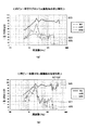
次に、ボビン一体型マグネシウム振動板、及びボビン一体型チタン振動板の高周波帯域での出力音圧特性を、夫々比較するため、図4(a)及び(b)にグラフとして示す。尚、グラフW3及びW6は出力音圧(太実線)を示すグラフであり、グラフW4及びW7は2次歪(細実線)を示すグラフであり、グラフW5及びW8は3次歪(破線)を示すグラフである。また、図4(a)は、30μm〜100μmの厚さを有するボビン一体型マグネシウム振動板を適用したスピーカー装置の特性を示している。 Next, in order to compare the output sound pressure characteristics in the high frequency band of the bobbin integrated magnesium diaphragm and the bobbin integrated titanium diaphragm, FIG. 4A and FIG. 4B are shown as graphs. Graphs W3 and W6 are graphs showing output sound pressure (thick solid line), graphs W4 and W7 are graphs showing secondary distortion (thin solid line), and graphs W5 and W8 are cubic distortion (dashed line). It is a graph to show. FIG. 4A shows characteristics of a speaker device to which a bobbin integrated magnesium diaphragm having a thickness of 30 μm to 100 μm is applied.
ボビン一体型マグネシウム振動板では、図4(a)のグラフW3に示すように、約3.5KHz〜約30KHzにかけて出力音圧が平坦になっている。一方、ボビン一体型チタン振動板では、図4(b)のグラフW6に示すように、約4KHz〜約15KHzにかけて出力音圧が平坦になっている。したがって、ボビン一体型マグネシウム振動板の方がボビン一体型チタン振動板より高域での音の再生帯域が広くとれ、尚且つボビン一体型マグネシウム振動板の方が超高域まで音の再生が可能であるということがわかる。 In the bobbin integrated type magnesium diaphragm, the output sound pressure is flat from about 3.5 KHz to about 30 KHz as shown by a graph W3 in FIG. On the other hand, in the bobbin integrated type titanium diaphragm, the output sound pressure is flat from about 4 KHz to about 15 KHz as shown by a graph W6 in FIG. Therefore, the bobbin integrated magnesium diaphragm has a wider sound reproduction band than the bobbin integrated titanium diaphragm, and the bobbin integrated magnesium diaphragm can reproduce sound up to a very high range. It turns out that it is.
即ち、可聴帯域内の約18KHz付近では、グラフW3及びW6を参照して理解されるように、ボビン一体型マグネシウム振動板は出力音圧が平坦であるのに対し、ボビン一体型チタン振動板の方では、破線領域E1(約18KHz)においてピークが生じている。また、18KHz以上30KHz以下の範囲では、グラフW3及びW6を参照して理解されるように、ボビン一体型マグネシウム振動板は出力音圧が平坦であるのに対し、ボビン一体型チタン振動板の方では、多くのピークやディップ(特定周波数の山と谷)が生じている(破線領域E2参照)。したがって、ボビン一体型マグネシウム振動板はボビン一体型チタン振動板に比して、より高域再生用の振動板として適していることがわかる。 That is, in the vicinity of about 18 KHz in the audible band, as understood with reference to the graphs W3 and W6, the bobbin integrated magnesium diaphragm has a flat output sound pressure, whereas the bobbin integrated titanium diaphragm has a flat output sound pressure. On the other hand, a peak occurs in the broken line area E1 (about 18 KHz). In addition, in the range of 18 kHz to 30 kHz, the bobbin integrated type magnesium diaphragm has a flat output sound pressure as compared with the graphs W3 and W6. Then, many peaks and dips (peaks and valleys of a specific frequency) are generated (see the broken line area E2). Therefore, it can be understood that the bobbin integrated type magnesium diaphragm is more suitable as a diaphragm for higher frequency reproduction than the bobbin integrated type titanium diaphragm.
また、図4(a)及び(b)には、2次、3次歪の特性がグラフとして示される。特に、可聴帯域3KHz〜20KHzにおけるボビン一体型マグネシウム振動板とボビン一体型チタン振動板の2次歪特性を比較すると、グラフW4及びW7を参照して理解されるように、ボビン一体型チタン振動板の方が多くのピークやディップが生じていることがわかる。さらに、上記同様の帯域におけるボビン一体型マグネシウム振動板とボビン一体型チタン振動板の3次歪特性を比較すると、グラフW5及びW8を参照して理解されるように、ボビン一体型チタン振動板の方がピークとディップとの出力音圧の差が大きいことがわかる。 4A and 4B show the characteristics of the second and third distortions as graphs. In particular, when comparing the secondary distortion characteristics of the bobbin integrated type magnesium diaphragm and the bobbin integrated type titanium diaphragm in the audible band of 3 KHz to 20 KHz, as understood with reference to the graphs W4 and W7, the bobbin integrated titanium diaphragm It can be seen that there are more peaks and dips. Further, comparing the third-order strain characteristics of the bobbin integrated magnesium diaphragm and the bobbin integrated titanium diaphragm in the same band as described above, as understood with reference to the graphs W5 and W8, the bobbin integrated titanium diaphragm It can be seen that the difference in the output sound pressure between the peak and the dip is larger.
これは、高周波帯域において、ボビン一体型チタン振動板の方がボビン一体型マグネシウム振動板より多くの歪成分を含んでいることを示すものである。したがって、ボビン一体型マグネシウム振動板の方がボビン一体型チタン振動板より高域再生用の振動板として適していることがわかる。 This indicates that the bobbin integrated titanium diaphragm contains more distortion components than the bobbin integrated magnesium diaphragm in the high frequency band. Therefore, it can be seen that the bobbin integrated type magnesium diaphragm is more suitable as a diaphragm for high-frequency reproduction than the bobbin integrated type titanium diaphragm.
尚、ボビン一体型マグネシウム振動板と、本例では特に示していないボビン一体型アルミニウム振動板とを比較した場合にも、ボビン一体型アルミニウム振動板の方が高周波帯域で多くのピークやディップが生じ歪成分を多く含んだ特性を示す。したがって、ボビン一体型マグネシウム振動板の方がボビン一体型アルミニウム振動板より高域再生用の振動板として適している。 When comparing the bobbin integrated type magnesium diaphragm and the bobbin integrated type aluminum diaphragm which is not particularly shown in this example, the bobbin integrated type aluminum diaphragm generates more peaks and dips in the high frequency band. It shows characteristics that contain a lot of distortion components. Therefore, the bobbin integrated type magnesium diaphragm is more suitable as a diaphragm for high frequency reproduction than the bobbin integrated type aluminum diaphragm.
以上に述べた特性は、主として、マグネシウムがチタンやアルミニウムより内部損失が大きく、比重が小さく、音速が大きく、且つ剛性などが高いという物理的特性によるものである。 The characteristics described above are mainly due to the physical characteristics that magnesium has higher internal loss, lower specific gravity, higher sound speed, higher rigidity, etc. than titanium and aluminum.
ここで、実際に、図5(a)の表1を参照して、マグネシウム、チタン及びアルミニウムの内部損失(tanδ)、密度ρ、及びE/ρ2を夫々比較検討する。尚、E/ρ2は、ヤング率Eを密度ρの2乗で除算したものであり、概ね、振動板の速度(音速)を表しているものと考えることができる。 Here, actually, referring to Table 1 in FIG. 5A, the internal loss (tan δ), density ρ, and E / ρ 2 of magnesium, titanium, and aluminum are respectively compared and examined. E / ρ 2 is obtained by dividing the Young's modulus E by the square of the density ρ, and can be considered to generally represent the speed (sound speed) of the diaphragm.
表1に示すように、マグネシウムの内部損失は0.005であり、チタン及びアルミニウムの内部損失は共に0.003である。よって、マグネシウムは、チタンやアルミニウムより内部損失が大きいことがわかる。このため、本発明のボビン一体型マグネシウム振動板を適用したスピーカー装置では、不要共振時に生じるピークやディップを小さくすることができ、歪の少ない音質が得られる。 As shown in Table 1, the internal loss of magnesium is 0.005, and the internal losses of titanium and aluminum are both 0.003. Therefore, it can be seen that magnesium has a larger internal loss than titanium or aluminum. For this reason, in the speaker device to which the bobbin integrated type magnesium diaphragm of the present invention is applied, it is possible to reduce the peak and dip generated at the time of unnecessary resonance, and to obtain a sound quality with less distortion.
また、マグネシウム、チタン及びアルミニウムの密度ρを夫々比較検討する。表1に示すように、マグネシウムの密度ρは、1780(Kg/m3)であり、チタンの密度ρは4400(Kg/m3)であり、アルミニウムの密度ρは2680(Kg/m3)である。よって、マグネシウムは、チタンやアルミニウムより比重が小さいことがわかる。このため、本発明のボビン一体型マグネシウム振動板を適用したスピーカー装置では、剛性を維持したまま感度を上げることができる。 Further, the density ρ of magnesium, titanium and aluminum will be compared and examined. As shown in Table 1, the density ρ of magnesium is 1780 (Kg / m 3 ), the density ρ of titanium is 4400 (Kg / m 3 ), and the density ρ of aluminum is 2680 (Kg / m 3 ). It is. Thus, it can be seen that magnesium has a lower specific gravity than titanium or aluminum. For this reason, in the speaker device to which the bobbin integrated type magnesium diaphragm of the present invention is applied, the sensitivity can be increased while maintaining the rigidity.
また、表1に示すように、マグネシウム振動板のE/ρ2は9.15×103であり、アルミニウム振動板のE/ρ2は9.65×103であり、チタン振動板のE/ρ2は6.15×103である。よって、マグネシウム振動板のE/ρ2は、アルミニウム振動板のE/ρ2と略同等レベルであり音速が大きいということがわかる。このため、本発明のボビン一体型マグネシウム振動板を適用したスピーカー装置は、音の反応が早く(トランジェント特性が良い)、高域の再生特性が良好となる。 Moreover, as shown in Table 1, E / ρ 2 of the magnesium diaphragm is 9.15 × 10 3 , E / ρ 2 of the aluminum diaphragm is 9.65 × 10 3 , and E / ρ 2 of the titanium diaphragm is 6.15 × 10 3 Therefore, E / [rho 2 of the magnesium diaphragm, it can be seen that a E / [rho 2 approximately equal levels of aluminum diaphragm sound velocity is large. For this reason, the speaker device to which the bobbin integrated type magnesium diaphragm of the present invention is applied has a fast sound response (good transient characteristics) and good high frequency reproduction characteristics.
ここで、スピーカーの感度とスピーカー材料の関係について検討する。ここで、スピーカーの感度(dB値)は、
SPL(dB)=20log10{P/(2×10−5)} (式1)
で表される。
Here, the relationship between speaker sensitivity and speaker material is examined. Here, the sensitivity (dB value) of the speaker is
SPL (dB) = 20 log 10 {P / (2 × 10 −5 )} (Formula 1)
It is represented by
また、上記の式1の右辺の音圧P(Pa)は、
P=(jω×ρ0×V×Sp)/2πr (式2)
で表される。ここで、「jω」は角速度、「ρ0」は空気密度、「V」は振動板速度、「Sp」は振動板有効面積、「r」は測定マイクまでの距離である。
Also, the sound pressure P (Pa) on the right side of
P = (jω × ρ 0 × V × Sp) / 2πr (Formula 2)
It is represented by Here, “jω” is the angular velocity, “ρ 0 ” is the air density, “V” is the diaphragm velocity, “Sp” is the diaphragm effective area, and “r” is the distance to the measurement microphone.
いま、振動板に適用する金属材料を変更することによって、その振動板重量に伴うスピーカーの感度の変化について考察するため、上記の式2における振動板速度Vに注目すると、振動板速度Vは、
V=F/Zm (式3)
で表される。ここで、「F」はボイスコイルに発生する力、「Zm」は機械インピーダンスである。また、機械インピーダンスZmは、
Zm=Rm+j(ωm0−1/ωC) (式4)
で表される。ここで、「Rm」は機械抵抗、「C」はコンプライアンス、「m0」は振動系重量である。
Now, in order to consider the change in sensitivity of the speaker with the weight of the diaphragm by changing the metal material applied to the diaphragm, focusing on the diaphragm speed V in
V = F / Zm (Formula 3)
It is represented by Here, “F” is a force generated in the voice coil, and “Zm” is a mechanical impedance. The mechanical impedance Zm is
Zm = Rm + j (ωm 0 −1 / ωC) (Formula 4)
It is represented by Here, “Rm” is mechanical resistance, “C” is compliance, and “m 0 ” is vibration system weight.
中高周波数域では、上記の式4において機械抵抗RmやコンプライアンスCは無視して構わないので、Zmの概算値はjωm0、即ち、Zm=jωm0となる。その結果、スピーカーの機構が同じで、かつ、同じ体積の振動板を有するスピーカーでは、振動板材料の比重の違いによってスピーカーの感度が変化することになる。
In the middle and high frequency range, the mechanical resistance Rm and the compliance C in the
即ち、振動板材料としてマグネシウムを使用した場合に、その振動系重量をm01、機械インピーダンスをZm1、振動板速度をV1、音圧をP1、及びスピーカーの感度をSPL1とする。また、振動板材料としてアルミニウムを使用した場合に、その振動系重量をm02、機械インピーダンスをZm2、振動板速度をV2、音圧をP2、及びスピーカーの感度をSPL2とする。さらに、振動板材料としてチタンを使用した場合に、その振動系重量をm03、機械インピーダンスをZm3、振動板速度をV3、音圧をP3、及びスピーカーの感度をSPL3とする。なお、いずれの振動板も体積は同じであるとする。 That is, when magnesium is used as the diaphragm material, its vibration system weight is m 01 , mechanical impedance is Zm1, diaphragm speed is V1, sound pressure is P1, and speaker sensitivity is SPL1. Also, when aluminum is used as the diaphragm material, its vibration system weight is m 02 , mechanical impedance is Zm2, diaphragm speed is V2, sound pressure is P2, and speaker sensitivity is SPL2. Furthermore, when titanium is used as the diaphragm material, its vibration system weight is m 03 , mechanical impedance is Zm3, diaphragm speed is V3, sound pressure is P3, and speaker sensitivity is SPL3. It is assumed that all diaphragms have the same volume.
そうすると、振動系重量m0は、m03>m02>m01となるので、上記の式4より機械インピーダンスZmは、Zm3>Zm2>Zm1となる。このため、上記の式3により振動板速度Vは、V1>V2>V3となり、上記の式2により音圧Pは、P1>P2>P3となる。このため、上記の式1により、スピーカーの感度SPLは、SPL1>SPL2>SPL3となる。よって、上記した条件の下では、スピーカーの感度は、マグネシウム振動板を有するスピーカー、アルミニウム振動板を有するスピーカー、チタン振動板を有するスピーカーの順に高いことがわかる。
Then, since the vibration system weight m 0 is m 03 > m 02 > m 01 , the mechanical impedance Zm is Zm3>Zm2> Zm1 from the
つまり、かかる結果は、スピーカーの感度を向上するためには、振動板の軽量化が必要であることを意味している。上記したように、アルミニウムやチタンは、マグネシウムに比べて密度ρが大きい。このため、アルミニウムやチタンを用いてボビン一体型振動板を作製するに際しては、スピーカーの感度低下を防止するため、その厚さを薄くする必要がある。しかし、その厚さを薄くすると、強度の求められるボビンの剛性E・t3が低下してしまうことになる。よって、ボビンの剛性を高めてスピーカーの感度を上げるためには、ボビン一体型振動板を作製する材料として、アルミニウムやチタンより比重の小さなマグネシウムが最も適していることがわかる。 That is, this result means that the weight of the diaphragm needs to be reduced in order to improve the sensitivity of the speaker. As described above, aluminum and titanium have a higher density ρ than magnesium. For this reason, when producing a bobbin integrated diaphragm using aluminum or titanium, it is necessary to reduce the thickness in order to prevent a decrease in sensitivity of the speaker. However, if the thickness is reduced, the bobbin rigidity E · t 3 for which strength is required is reduced. Therefore, in order to increase the rigidity of the bobbin and increase the sensitivity of the speaker, it can be seen that magnesium having a specific gravity smaller than aluminum or titanium is most suitable as a material for producing the bobbin integrated diaphragm.
例えば、厚さ30μmのアルミニウム振動板を有するスピーカーの感度と同じ感度にするためには、理論上、マグネシウム振動板では厚さ45μmにする必要があり、チタン振動板では厚さ18μmにする必要がある。また、それらの各振動板の厚さに対応する剛性値E・t3を算出した結果、図6の表3を得ることができた。ここで、Eはヤング率であり、tは振動板の厚さである。表3に示すように、厚さ30μmのアルミニウム振動板の剛性値は、1.87×10⁻³であり、厚さ45μmのマグネシウム振動板の剛性値は、2.64×10⁻³であり、厚さ18μmのチタン振動板の剛性値は、6.94×10⁻⁴である。よって、スピーカーの感度が同一の条件の下では、マグネシウム振動板、アルミニウム振動板、チタン振動板の順に剛性値が高いことがわかる。 For example, in order to obtain the same sensitivity as that of a speaker having an aluminum diaphragm having a thickness of 30 μm, it is theoretically necessary that the thickness is 45 μm for a magnesium diaphragm and 18 μm for a titanium diaphragm. is there. Further, as a result of calculating the rigidity value E · t 3 corresponding to the thickness of each of the diaphragms, Table 3 in FIG. 6 was obtained. Here, E is Young's modulus, and t is the thickness of the diaphragm. As shown in Table 3, the rigidity value of the 30 μm thick aluminum diaphragm is 1.87 × 10 −3 , the rigidity value of the 45 μm magnesium diaphragm is 2.64 × 10 −3 , and the thickness is 18 μm. The rigidity value of the titanium diaphragm is 6.94 × 10 −4 . Therefore, it can be seen that the rigidity value is higher in the order of the magnesium diaphragm, the aluminum diaphragm, and the titanium diaphragm under the condition that the sensitivity of the speaker is the same.
また、マグネシウムはアルミニウムやチタンと比較して比重が小さいので、ボビン一体型振動板を厚くして剛性を上げることができる。つまり、剛性を上げるために厚さを厚くした場合、その分の重量増を考慮しても、同じ剛性のアルミニウムやチタンのボビン一体型振動板と比較して重量を軽くすることができる。よって、スピーカーの感度を低下させることなく、軽量化が可能となる。 Moreover, since magnesium has a smaller specific gravity than aluminum or titanium, the bobbin integrated diaphragm can be thickened to increase rigidity. That is, when the thickness is increased in order to increase the rigidity, the weight can be reduced as compared with the aluminum or titanium bobbin integrated diaphragm having the same rigidity even if the increase in the weight is taken into consideration. Therefore, the weight can be reduced without reducing the sensitivity of the speaker.
また、本発明のボビン一体型マグネシウム振動板をスピーカー装置に適用することにより、上記の他にも以下の作用効果を奏する。 Further, by applying the bobbin integrated type magnesium diaphragm of the present invention to a speaker device, the following effects can be obtained in addition to the above.
まず、放熱効果が高くなるので、耐入力の限界値を高く設定することができる。ここで、実際に、図5(b)の表2を参照して、マグネシウム、チタン及びアルミニウムの熱伝導率を夫々比較検討する。表2に示すように、マグネシウムの熱伝導率は156.0W・m−1・K−1であり、チタンの熱伝導率は21.9W・m−1・K−1であり、アルミニウムの熱伝導率は237.0W・m−1・K−1である。なお、その各熱伝導率は気温27℃のときの値である。よって、アルミニウムはそれらの金属中で最も熱伝導率が高く、マグネシウムより放熱性に優れた素材であることがわかる。しかし、上記したように、マグネシウムは、アルミニウムやチタンよりも内部損失が大きい。このため、熱伝導率だけでなく内部損失も考慮した場合には、マグネシウムの方がアルミニウムより高域再生用の振動板として適している。加えて、本発明のボビン一体型マグネシウム振動板は、ボビンと振動板が一体的に成形されている。このため、ボイスコイルで発生した熱をボビンを通じて振動板側へ効率よく伝達することができ、さらにその熱をスピーカー装置の外部空間、即ち空気中へと放熱することができ、上記の効果を得ることができる。 First, since the heat dissipation effect becomes high, the limit value of input resistance can be set high. Here, actually, the thermal conductivities of magnesium, titanium, and aluminum are respectively compared and examined with reference to Table 2 in FIG. As shown in Table 2, the thermal conductivity of magnesium is 156.0 W · m −1 · K −1 , the thermal conductivity of titanium is 21.9 W · m −1 · K −1 , and the heat of aluminum The conductivity is 237.0 W · m −1 · K −1 . Each thermal conductivity is a value at an air temperature of 27 ° C. Therefore, it can be seen that aluminum has the highest thermal conductivity among these metals and is a material having better heat dissipation than magnesium. However, as described above, magnesium has a larger internal loss than aluminum or titanium. For this reason, when considering not only thermal conductivity but also internal loss, magnesium is more suitable as a diaphragm for high-frequency reproduction than aluminum. In addition, in the bobbin integrated type magnesium diaphragm of the present invention, the bobbin and the diaphragm are integrally formed. For this reason, the heat generated by the voice coil can be efficiently transferred to the diaphragm side through the bobbin, and the heat can be dissipated to the outside space of the speaker device, that is, into the air, thereby obtaining the above effect. be able to.
また、音響特性などの特性にばらつきが生じるのを防止できると共に、ボイスコイルから伝わる振動を損失無く振動板側へ伝達することが可能となる。本発明のボビン一体型マグネシウム振動板は、ボビンと振動板が一体的に成形されるので、ボビンと振動板の接合に際して接着剤は使用されない。よって、その振動板を適用したスピーカー装置は、接着剤の影響を受けないため、上記の効果を得ることができる。 In addition, it is possible to prevent variations in characteristics such as acoustic characteristics, and it is possible to transmit vibration transmitted from the voice coil to the diaphragm side without loss. In the bobbin integrated type magnesium diaphragm of the present invention, since the bobbin and the diaphragm are integrally formed, no adhesive is used for joining the bobbin and the diaphragm. Therefore, since the speaker device to which the diaphragm is applied is not affected by the adhesive, the above effect can be obtained.
また、接着剤などに含まれる揮発性有機化合物(VOC;Volatile Organic Compounds)の排出を低減することができる。これは、上記したように、本発明のボビン一体型マグネシウム振動板の製造時、即ち、ボビンと振動板の接合時に接着剤を使用しないからである。このため、スピーカー製造時に作業者の安全性を確保できると共に環境浄化にも貢献し得る。 In addition, emission of volatile organic compounds (VOC) contained in the adhesive or the like can be reduced. This is because, as described above, no adhesive is used when the bobbin integrated type magnesium diaphragm of the present invention is manufactured, that is, when the bobbin and the diaphragm are joined. For this reason, the safety of the operator can be ensured at the time of manufacturing the speaker, and it can also contribute to environmental purification.
特に本例では、ボビン一体型マグネシウム振動板の厚さを30μm〜100μmの範囲内に形成しているので、さらに以下のような効果を奏する。 In particular, in this example, since the thickness of the bobbin integrated type magnesium diaphragm is formed in the range of 30 μm to 100 μm, the following effects are further obtained.
即ち、30μm以下の厚さになるとボビン一体型マグネシウム振動板は、一般的に、酸化皮膜の影響受けて硬度が増し、高内部損失といったマグネシウム特有の物理的特性が失われてしまうが、これを回避することができる。なお、ボビン一体型マグネシウム振動板の厚さの下限は、圧延時に生じる異常結晶成長により30μmが限界である。また、100μm以上の厚さにするとボビン一体型マグネシウム振動板の質量が増加するため、スピーカーの能率が低下するといった不具合が発生するが、これも回避することができる。よって、本例に係るボビン一体型マグネシウム振動板は、酸化の影響を受けにくく、高内部損失を維持でき、感度低下を損なうことなく、且つ低歪などを実現できるので、高周波帯域で高品質な音再生が可能となる。 That is, when the thickness is 30 μm or less, the bobbin integrated type magnesium diaphragm generally increases the hardness due to the influence of the oxide film, and the physical characteristics peculiar to magnesium such as high internal loss are lost. It can be avoided. The lower limit of the thickness of the bobbin integrated magnesium diaphragm is 30 μm due to abnormal crystal growth that occurs during rolling. Further, when the thickness is 100 μm or more, the mass of the bobbin integrated type magnesium diaphragm increases, which causes a problem that the efficiency of the speaker is lowered, but this can also be avoided. Therefore, the bobbin integrated type magnesium diaphragm according to the present example is not easily affected by oxidation, can maintain high internal loss, can realize low distortion without impairing sensitivity reduction, and has high quality in a high frequency band. Sound playback is possible.
尚、ボビン一体型マグネシウム振動板の振動板部分の有効面積を大きくすると高域限界周波数fhが可聴帯域に生じてくるため歪の多く含んだ音質になってしまうという問題が生じるが、一般的に高域再生用の振動板は、振動板の有効面積を小さくし、且つ後述するようにドーム型、或いはセミドーム型などの態様で使用されるため、そのような不具合は解消される。 Note that if the effective area of the diaphragm portion of the bobbin integrated type magnesium diaphragm is increased, the high frequency limit frequency fh is generated in the audible band, so that there is a problem that the sound quality includes a lot of distortion. Since the diaphragm for high frequency reproduction reduces the effective area of the diaphragm and is used in a dome type or semi-dome type as described later, such a problem is solved.
[ボビン一体型マグネシウム振動板を使用したスピーカー装置]
上述の圧延工程により製造した30μm〜100μmの厚さを有するボビン一体型マグネシウム振動板を高域再生可能なダイナミック形スピーカー装置に適用した各種形態例を図7及び図8に示す。尚、以下の各種形態例に示すボビン一体型マグネシウム振動板の形状は、上述の圧延工程により製作したマグネシウムシート24をプレス装置などにより成形するものであるが、その成形方法は本発明の特徴ではなく、既知の各種の方法を適用可能であるため説明は省略する。
[Speaker device using bobbin integrated magnesium diaphragm]
7 and 8 show various embodiments in which a bobbin integrated type magnesium diaphragm having a thickness of 30 μm to 100 μm manufactured by the rolling process described above is applied to a dynamic speaker device capable of high-frequency reproduction. The shape of the bobbin integrated type magnesium diaphragm shown in the following various embodiments is that the
(セミドーム型のダイナミック形スピーカー装置への適用例)
図7(a)は、セミドーム型振動板1a及びボビン1bを有するボビン一体型マグネシウム振動板1の断面図を示す。図7(b)は、そのボビン一体型マグネシウム振動板1をダイナミック形スピーカー装置に適用した一例を断面図として示す。
(Example of application to a semi-dome type dynamic speaker device)
FIG. 7A shows a cross-sectional view of a bobbin integrated
先ず、図7(b)を参照して、セミドーム型のダイナミック形スピーカー装置500の基本構成及び基本原理について述べる。セミドーム型のダイナミック形スピーカー装置500は、図7(b)に示すように、ボビン一体型マグネシウム振動板1、エッジ2、ボイスコイル3などの振動系と、ツボヨーク5、マグネット6、プレート7などの磁気回路系と、を備えている。
First, the basic configuration and basic principle of the semi-dome type
ボビン一体型マグネシウム振動板1は、セミドーム型振動板1aと略円筒状の形状をなすボビン1bとが一体的に成形されてなる。セミドーム型振動板1aは、スピーカー側に開口を有する略半円球状(いわゆる、セミドーム形状)の振動板である。セミドーム型振動板1aの外周縁部には、エッジ2の内周縁部が取り付けられている。エッジ2の外周縁部2aは、筐体をなす樹脂プレート4の一上端面とスピーカーの周方向に沿って固定されている。ボビン1bの外周壁の下端部には、ボイスコイル3が巻かれている。
The bobbin integrated
また、ボビン1bの外周壁は、上面に開口を有する略円筒形状をなすツボヨーク5の内周壁と一定の間隔を隔てて対向している。一方、ボビン1bの内周壁は、円板形状のマグネット6の外周壁、及びマグネット6より若干大なる直径を有する円板形状のプレート7の内周壁と夫々一定の間隔を隔てて対向している。これにより、プレート7の外周壁と、ツボヨーク5の内周壁との間には磁気ギャップが形成されている。
The outer peripheral wall of the
以上のように構成されたセミドーム型のダイナミック形スピーカー装置500では、一様な磁界中にあるボイスコイル3に音声電流が流れると電磁作用の原理により、ボビン一体型マグネシウム振動板1がそのスピーカーの軸方向に上下するように振動し、セミドーム型振動板1aから音波が放射される。
In the semi-dome type
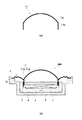
(ドーム型のダイナミック形スピーカー装置への適用例)
図8(a)は、ドーム型振動板11a及びボビン11bを有するボビン一体型マグネシウム振動板11の断面図を示す。図8(b)は、ボビン一体型マグネシウム振動板11をダイナミック形スピーカー装置に適用した一例を断面図として示す。
(Example of application to a dome-shaped dynamic speaker device)
FIG. 8A shows a cross-sectional view of a bobbin integrated
ドーム型のダイナミック形スピーカー装置600は、上記したセミドーム型のダイナミック形スピーカー装置500と略同様の構成である。このため、セミドーム型のダイナミック形スピーカー装置500と同様の構成要素には同一の符号を付し、その説明を省略する。しかし、前者と後者とは、ボビン一体型マグネシウム振動板の形状が異なっている。即ち、前者のボビン一体型マグネシウム振動板11は、ドーム型に成形されたドーム型振動板11aと略円筒形状をなすボビン11bとが一体的に成形されている。つまり、ダイナミック形スピーカー装置には、セミドーム型のボビン一体型マグネシウム振動板1に限らず、ドーム型のボビン一体型マグネシウム振動板11を適用することもできる。
The dome type
[変形例]
上記の実施例では、セミドーム型振動板1aを有するボビン一体型マグネシウム振動板1、或いはドーム型振動板11aを有するボビン一体型マグネシウム振動板11を、ダイナミック形スピーカー装置に適用した。しかし、これに限らず、コーン型振動板を有するボビン一体型マグネシウム振動板をダイナミック形スピーカー装置に適用することも可能である。この場合、低音再生時の振動による振動板やボビンの強度を保つため、そのボビン一体型マグネシウム振動板は100μm以上の厚さに成形するのが好ましい。また、コーン型振動板以外にも各種形状の振動板を有するボビン一体型マグネシウム振動板をダイナミック形スピーカー装置に適用することも可能である。
[Modification]
In the above embodiment, the bobbin integrated
1、11 ボビン一体型マグネシウム振動板
1a セミドーム型振動板
11a ドーム型振動板
1b、11b ボビン
20 マグネシウムの基材
24 マグネシウムシート
22 恒温槽
23 圧延機
200 圧延工程
500 セミドーム型のダイナミック形スピーカー装置
600 ドーム型のダイナミック形スピーカー装置
DESCRIPTION OF
Claims (8)
前記加熱された状態の前記マグネシウムの基材を圧延してマグネシウムシートを製作する圧延工程と、
前記マグネシウムシートを成形して、ボビンと振動板を一体的に作製する成形工程と、を備えることを特徴とするボビン一体型マグネシウム振動板の製造方法。 A heating step of heating the magnesium substrate;
Rolling the magnesium substrate in the heated state to produce a magnesium sheet; and
Forming a magnesium sheet, and forming a bobbin and a diaphragm integrally; and a manufacturing method of a magnesium bobbin integrated diaphragm.
A speaker device comprising the speaker diaphragm according to claim 6.
Priority Applications (3)
| Application Number | Priority Date | Filing Date | Title |
|---|---|---|---|
| JP2004148873A JP2005333322A (en) | 2004-05-19 | 2004-05-19 | Bobbin-integrated magnesium diaphragm, its manufacturing method, and speaker device using the same |
| US11/127,322 US20050257999A1 (en) | 2004-05-19 | 2005-05-12 | Bobbin integrated type magnesium diaphragm, manufacturing method thereof, and speaker device using the diaphragm |
| EP05252984A EP1599066A3 (en) | 2004-05-19 | 2005-05-16 | Bobbin integrated type magnesium diaphragm, manufacturing method thereof, and speaker device using the diaphragm |
Applications Claiming Priority (1)
| Application Number | Priority Date | Filing Date | Title |
|---|---|---|---|
| JP2004148873A JP2005333322A (en) | 2004-05-19 | 2004-05-19 | Bobbin-integrated magnesium diaphragm, its manufacturing method, and speaker device using the same |
Publications (1)
| Publication Number | Publication Date |
|---|---|
| JP2005333322A true JP2005333322A (en) | 2005-12-02 |
Family
ID=34941312
Family Applications (1)
| Application Number | Title | Priority Date | Filing Date |
|---|---|---|---|
| JP2004148873A Pending JP2005333322A (en) | 2004-05-19 | 2004-05-19 | Bobbin-integrated magnesium diaphragm, its manufacturing method, and speaker device using the same |
Country Status (3)
| Country | Link |
|---|---|
| US (1) | US20050257999A1 (en) |
| EP (1) | EP1599066A3 (en) |
| JP (1) | JP2005333322A (en) |
Cited By (2)
| Publication number | Priority date | Publication date | Assignee | Title |
|---|---|---|---|---|
| WO2009107938A2 (en) * | 2008-02-28 | 2009-09-03 | 일진경금속 주식회사 | Magnesium diaphragm with built-in bobbin and method for same |
| KR101029527B1 (en) * | 2010-06-28 | 2011-04-18 | 일진경금속 주식회사 | Manufacturing method of bobbin combination Mg diaphragm |
Families Citing this family (8)
| Publication number | Priority date | Publication date | Assignee | Title |
|---|---|---|---|---|
| FR2854021B1 (en) * | 2003-04-16 | 2006-03-31 | Focal Jmlab | ACOUSTIC TRANSDUCER IN DIRECT RADIATION DIRECT RADIATION BERYLLIUM ACRYLIC, FOR CONCAVE-SHAPED MEMBRANE, FOR AUDIO APPLICATIONS ESPECIALLY FOR ACOUSTIC SPEAKERS |
| GB0426143D0 (en) * | 2004-11-26 | 2004-12-29 | Element Six Ltd | Rigid three-dimensional components |
| EP1989915A1 (en) * | 2006-02-16 | 2008-11-12 | Bang & Olufsen IcePower A/S | A micro-transducer with improved perceived sound quality |
| JP2010288099A (en) * | 2009-06-12 | 2010-12-24 | Hosiden Corp | Loudspeaker |
| GB201102547D0 (en) * | 2011-02-14 | 2011-03-30 | Element Six Ltd | Coated speaker dome and coated diamond products |
| US9226074B2 (en) * | 2013-11-21 | 2015-12-29 | Bose Corporation | Surround with variations of concavity |
| JP6418556B2 (en) * | 2015-12-17 | 2018-11-07 | オンキヨー株式会社 | Speaker diaphragm, speaker including the same, and method for manufacturing speaker diaphragm |
| US10555085B2 (en) * | 2017-06-16 | 2020-02-04 | Apple Inc. | High aspect ratio moving coil transducer |
Family Cites Families (4)
| Publication number | Priority date | Publication date | Assignee | Title |
|---|---|---|---|---|
| US1951873A (en) * | 1931-01-13 | 1934-03-20 | Western Electric Co | Method of making vibratory devices |
| US2934461A (en) * | 1956-09-28 | 1960-04-26 | Dow Chemical Co | Rolling magnesium alloy |
| US5062140A (en) * | 1988-04-27 | 1991-10-29 | Sony Corporation | Induction speaker |
| JP2002369284A (en) * | 2001-06-04 | 2002-12-20 | Foster Electric Co Ltd | Diaphragm for speaker, and method for manufacturing the same |
-
2004
- 2004-05-19 JP JP2004148873A patent/JP2005333322A/en active Pending
-
2005
- 2005-05-12 US US11/127,322 patent/US20050257999A1/en not_active Abandoned
- 2005-05-16 EP EP05252984A patent/EP1599066A3/en not_active Withdrawn
Cited By (3)
| Publication number | Priority date | Publication date | Assignee | Title |
|---|---|---|---|---|
| WO2009107938A2 (en) * | 2008-02-28 | 2009-09-03 | 일진경금속 주식회사 | Magnesium diaphragm with built-in bobbin and method for same |
| WO2009107938A3 (en) * | 2008-02-28 | 2009-11-26 | 일진경금속 주식회사 | Magnesium diaphragm with built-in bobbin and method for same |
| KR101029527B1 (en) * | 2010-06-28 | 2011-04-18 | 일진경금속 주식회사 | Manufacturing method of bobbin combination Mg diaphragm |
Also Published As
| Publication number | Publication date |
|---|---|
| EP1599066A2 (en) | 2005-11-23 |
| US20050257999A1 (en) | 2005-11-24 |
| EP1599066A3 (en) | 2006-12-06 |
Similar Documents
| Publication | Publication Date | Title |
|---|---|---|
| US20050257999A1 (en) | Bobbin integrated type magnesium diaphragm, manufacturing method thereof, and speaker device using the diaphragm | |
| US10390162B2 (en) | Method of forming an acoustic transducer | |
| KR101814951B1 (en) | Speaker and earphone | |
| WO2011003333A1 (en) | Speaker | |
| TWM529998U (en) | Earphone of moving coil piezoelectric two-tone speaker | |
| JP2006303770A (en) | Piezoelectric vibration element and sound transducing apparatus provided with the piezoelectric vibration element | |
| CN1774954A (en) | Acoustic transducer | |
| WO2009090746A1 (en) | Diaphragm for speaker, and speaker device | |
| KR100638057B1 (en) | Double Diaphragm Micro speaker | |
| JP4152804B2 (en) | Magnesium diaphragm, manufacturing method thereof, and speaker device using the diaphragm | |
| JP2011130051A (en) | Capacitor microphone unit and capacitor microphone | |
| JP2007043522A (en) | Diaphragm for speaker device | |
| JP2013236371A (en) | Diaphragm for speaker integrally formed with different degrees of rigidity in one polymeric film | |
| KR101738516B1 (en) | Piezoelectric Speaker | |
| JP2018504078A (en) | Nonflammable piezo piezoelectric speaker device | |
| KR20070025875A (en) | Structure of dual diaphragm and high quality and high power microspeaker | |
| JP2005333321A (en) | Speaker device and method for manufacturing magnesium edge therefor | |
| JP2007043631A (en) | Speaker using cone-type piezoelectric diaphragm | |
| JP4032995B2 (en) | Speaker manufacturing method | |
| JPH08228392A (en) | Speaker and its production | |
| TW202339521A (en) | Acoustic output device | |
| KR20070102335A (en) | Structure of rib type diaphragm and high quality and high power microspeaker | |
| JP6563262B2 (en) | Dynamic headphone unit and method for setting resonance frequency of diaphragm | |
| JP2006319933A (en) | Piezo-vibrating microphone unit | |
| JP2007235552A (en) | Speaker, diaphragm for dome speaker, and method of manufacturing diaphragm for dome speaker |
Legal Events
| Date | Code | Title | Description |
|---|---|---|---|
| A621 | Written request for application examination |
Free format text: JAPANESE INTERMEDIATE CODE: A621 Effective date: 20070419 |
|
| A977 | Report on retrieval |
Free format text: JAPANESE INTERMEDIATE CODE: A971007 Effective date: 20090618 |
|
| A131 | Notification of reasons for refusal |
Free format text: JAPANESE INTERMEDIATE CODE: A131 Effective date: 20090630 |
|
| A02 | Decision of refusal |
Free format text: JAPANESE INTERMEDIATE CODE: A02 Effective date: 20091208 |