JP4032995B2 - Speaker manufacturing method - Google Patents
Speaker manufacturing method Download PDFInfo
- Publication number
- JP4032995B2 JP4032995B2 JP2003055530A JP2003055530A JP4032995B2 JP 4032995 B2 JP4032995 B2 JP 4032995B2 JP 2003055530 A JP2003055530 A JP 2003055530A JP 2003055530 A JP2003055530 A JP 2003055530A JP 4032995 B2 JP4032995 B2 JP 4032995B2
- Authority
- JP
- Japan
- Prior art keywords
- speaker
- yoke
- protector
- coupled
- forming
- Prior art date
- Legal status (The legal status is an assumption and is not a legal conclusion. Google has not performed a legal analysis and makes no representation as to the accuracy of the status listed.)
- Expired - Fee Related
Links
Images


Landscapes
- Audible-Bandwidth Dynamoelectric Transducers Other Than Pickups (AREA)
- Details Of Audible-Bandwidth Transducers (AREA)
Description
【0001】
【発明の属する技術分野】
本発明は音響機器や移動体通信機等に使用されるスピーカの製造方法に関するものである。
【0002】
【従来の技術】
従来の技術を図9の携帯電話に用いられるマイクロスピーカの分解側断面図および図10の音圧周波数特性図により説明する。同図によると、1aは磁性材料よりなる有底円筒状のヨークであり、1bはこのヨーク1aの底面に接着結合された円筒状のマグネットであり、1cはこのマグネット1b上に接着結合されたプレートであり、これらにより磁気回路1が形成されるとともに、前記ヨーク1aの側面と前記プレート1cの側面間には磁気ギャップ1dが設けられている。
【0003】
2は樹脂成形されたフレームであり、前記ヨーク1aをインサート成形により一体化して形成したり、フレーム2の成形後にヨーク1aを圧入や接着により、フレーム2とヨーク1aの一体化を図っている。
【0004】
3は外周が前記フレーム2に接着結合されるとともに、中央部に前記磁気ギャップ1dに嵌め込まれるボイスコイル4の上端を接着結合した振動板である。
【0005】
なお、振動板3が薄く取り扱いが困難な場合には、振動板3に予めリング3aを接着結合して振動板として取り扱い、フレーム2との結合作業を容易にしている構成のものもあるが、このリング3aの貼り付けは振動板3の厚み、大きさ、剛性など取り扱いの容易性から適宜その要不要はスピーカの種類によって判断される。
【0006】
5は振動板3への外力からの影響の排除や塵埃の防止のために前記振動板3上を覆うように装着されてなるフレーム2に装着されてなる樹脂製のプロテクタであり、その中央部には制動布6を貼り付けるための開口部5bを有する凹部5aが設けられている。
【0007】
なお、制動布6はスピーカの共振周波数における音圧出力を抑制して音圧周波数特性の平坦化を図るものである。
【0008】
図10の音圧周波数特性図のaは制動布を貼り付ける前の音圧周波数特性を示している。通常は凹部5aに制動布6を貼り付けることで音圧出力を平坦としている。
【0009】
なお、制動布を用いた音響変換器の例としては特許文献1に見られるものがある。
【0010】
【特許文献1】
特開昭61−206400号公報
【0011】
【発明が解決しようとする課題】
以上のように構成されたスピーカにおいては、スピーカの形状、寸法、使用される振動板3の種類によって、音圧周波数特性が異なり、共振周波数も異なるため、また、スピーカが搭載される電子機器から要求される音響出力特性によって、夫々に応じた繊維の太さ、織布の粗さの異なった、多数の種類の制動布6を準備する必要があり、プロテクタ5への貼り付けが煩雑となり、また、部品管理も複雑なものとなっていた。
【0012】
【課題を解決するための手段】
上記課題を解決するために、本発明のスピーカの製造方法の請求項1に記載のものは、磁気回路とヨークに装着されたフレームと外周が前記フレームに結合され中央部に磁気回路の磁気ギャップに嵌め込まれるボイスコイルの上端を結合した振動板とでスピーカを形成するスピーカ形成工程と、前記スピーカの音響特性を測定し、測定された音響特性により予め設定した複数分類のいずれかに分類する分類工程と、予め設定されたスピーカの前記音響特性に応じてプロテクタの表面に微小レーザ照射により複数の微小の孔部を設ける制動部形成工程と、分類工程で音響特性により分類されたスピーカとこの分類に対応する制動部形成工程で形成された複数の微小の孔部を有するプロテクタを前記スピーカに装着する工程とからなるスピーカの製造方法であり、スピーカの音響特性のばらつきに対応したプロテクタの供給が可能となり、極めて効率の良い製造方法を可能とするものである。
【0013】
本発明のスピーカの製造方法の請求項2に記載のものは磁気回路とこの磁気回路のヨークに装着されたフレームと外周が前記フレームに結合され中央部に前記磁気ギャップに嵌め込まれるボイスコイルの上端を結合した振動板とでスピーカを形成するスピーカ形成工程と、このスピーカ形成工程で形成されたスピーカのボイスコイルに特性測定用の電気信号を入力し、前記スピーカの音響特性を測定する音圧周波数特性測定工程と、前記測定された音響特性に応じてプロテクタにレーザ照射により複数の制動用微小の孔部を形成する制動部形成工程と、制動部形成工程を経たプロテクタを前記スピーカ形成工程により得られたスピーカに装着するプロテクタ装着工程からなるスピーカの製造方法であり、製造されたスピーカ個々に応じたプロテクタを装着することを可能として、音響特性に優れたスピーカの製造を可能とするものである。
【0014】
本発明のスピーカの製造方法の請求項3に記載のものは磁気回路とこの磁気回路のヨークに装着されたフレームと外周が前記フレームに結合され中央部に前記磁気ギャップに嵌め込まれるボイスコイルの上端を結合した振動板とでスピーカを形成するスピーカ形成工程と、スピーカの音響特性に応じてプロテクタにレーザ照射により複数の制動用微小の孔部を形成する制動部形成工程と、制動部形成工程を経たプロテクタを前記スピーカ形成工程により得られたスピーカに装着するプロテクタ装着工程からなるスピーカの製造方法であって、制動部形成工程での製造条件を別工程の音圧周波数特性測定工程で予め測定されたデータに基づくもので行なうものであり、スピーカの個々の使用部品のばらつきやスピーカ組み立て工程での組み立てのばらつきが安定して、僅少となった場合に、予め測定された条件で制動部形成工程を稼動させるので、製造工程の短縮化、音圧周波数特性測定工程の別工程化による共用化で製造工程のコストダウンが図れるものである。
【0015】
【発明の実施の形態】
以下、本発明のスピーカの製造方法の一実施の形態について図1から図8により説明する。
【0016】
なお、説明にあたっては従来技術と同一部分には同一番号を附与して説明を省略して説明する。
【0017】
(実施の形態1)
図1は本発明のスピーカの製造方法による一実施の形態の携帯電話用の10mm径のマイクロスピーカの上面図であり、図2は同側断面図であり、図3は同分解側断面図であり、同図4は同音圧周波数特性図であり、図5は同展開例のマイクロスピーカの上面図であり、図6は同側断面図である。
【0018】
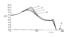
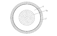
同図により従来技術との相違点のみ説明すると、10はステンレス製の薄板(例えばt=80μm)からなるプロテクタであり、10aはこのプロテクタにYAGレーザの照射によって穿孔された微小の孔部であり、略φ100μmの孔、略225個から形成されている。なお、孔径が大きすぎると塵埃の通過を許し、プロテクタとしての役割を果たさず150μm程度が限界と考えられ、小さすぎると振動板3の振動を抑制し、音圧は低下することになる。φ150μm〜30μm程度の孔径がプロテクタとして適当である。なお、音圧は孔部の孔径と設けられる孔部の数量によって適宜決定すれば良いものである。
【0019】
なお、図4はレーザ照射による微小の孔部10aの大きさ(プロテクタの表面側)とその数量と音圧周波数特性の関係を示すものであり、bはφ100μmの微小の孔部225個をレーザ照射により設けたものであり、cはφ80μmの微小の孔部225個をレーザ照射により設けたものであり、dはφ50μmの微小の孔部225個をレーザ照射により設けたものである。
【0020】
また、aは制動布6を用いない開口部5bを設けただけの図10に記載の従来のスピーカの音圧周波数特性を示すものである。
【0021】
この図により、微小の孔部10aを設けたものが音圧周波数特性の平坦化に効果のあることが確認された。
【0022】
なお、この微小の孔部10aをレーザ照射により設けたものは従来の制動布を用いたものと遜色のない音響周波数特性を示すことが確認された。
【0023】
以上のプロテクタ10は制動布を貼り付ける凹部を設ける必要もなく、孔加工も不要でプロテクタの金型、加工コストの低減が可能となる。
【0024】
また、レーザ照射はプロテクタ10の裏面側から行なわれる。レーザ照射の照射部分(裏面側)は高熱により溶かされて大径の孔となり、表面側に近づくほどそのレーザ照射の影響が減衰されて孔は小径となる。この表面側の孔径の管理はレーザの出力、照射径、照射時間によって任意に調整できる。
【0025】
なお、上述のように表面側の孔径を小さくすることで、塵埃の孔部分からの侵入や溜まりの抑制が行なえるものであり、150μm以下の径とすることが望ましい。
【0026】
また、プロテクタの微小の孔部10aの径を裏面側の径を大きくし、表面側に向かうほど小さいようにしたので、微小の孔部10aを振動板3とプロテクタ10間の空気室の一部として容量の増大に寄与させることができるものであり、携帯電話などに搭載するスピーカ(レシーバ)の場合はスピーカが小型であるために、上記微小の孔部10aによる空気室の容量の増加によって共振周波数を低くすることができ、共振周波数の調整の余裕を持たせることで設計の余裕度を増したり、音圧の向上に寄与できるものである。
【0027】
図5および図6により本実施形態の展開例について本実施形態との相違点のみ説明すると、11はプロテクタであり、微小孔11aを中央周辺まで設けたものである。以上のように微小孔11aの設定位置を拡大したことで、スピーカの外方への放音を従来のように中央の開口部5bを介することがないので、プロテクタ11の機械的強度を損なうことなく、音響抵抗を抑制して音響出力の向上を図ることができるものである。
【0028】
なお、微小孔11aはプロテクタ11のフレーム2との周辺まで設けることも可能であるが、フレーム2との周辺は機器への装着時に機器側によって覆われてしまう可能性もあるので、プロテクタ11のフレーム2の周辺まで微小孔11aを設けることは機器側との装着関係を確認した上で行なう必要がある。
【0029】
(実施の形態2)
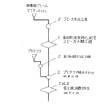
図7は本発明のスピーカの製造方法の一実施の形態の製造工程図であり、主として請求項1について説明するものである。
【0030】
20はヨーク1aとこのヨーク1aの底面に結合されたマグネット1bとこのマグネット1b上に結合された前記ヨーク1aの側面とで磁気ギャップ1dを設けたプレート1cとで形成された磁気回路1と前記ヨーク1aに装着されたフレーム2と外周が前記フレーム2に結合され中央部に前記磁気ギャップ1dに嵌め込まれるボイスコイル4の上端を結合した振動板3とでスピーカを形成するスピーカ形成工程であり、21はこのスピーカ形成工程で形成されたスピーカのボイスコイル4に特性測定用の電気信号を入力し、前記スピーカの音響特性を測定し、測定された音響特性により予め設定した複数分類のいずれかに分類する分類工程(測定用のプロテクタを装着して測定・分類する場合も有り)であり、22は別工程の分類工程21の分類に対応して設定されたスピーカの前記音響特性に応じてプロテクタ10の表面にレーザ照射により複数の微小の孔部を複数分類に分けて予め設ける制動部形成工程であり、23は前記分類工程で音響特性により分類されたスピーカをその分類に対応する分類の前記制動部形成工程で予め形成された複数の微小の孔部を有するプロテクタ10を前記スピーカに装着するプロテクタ組み合わせ装着工程である。
【0031】
分類工程21で分類されたスピーカは、プロテクタ10にレーザ照射により複数の微小の孔部を設ける制動部形成工程22で複数種の分類毎に製作されたプロテクタ10に対応するものとプロテクタ組み合わせ装着工程で組み合わせ完成され、スピーカの音響特性に応じたプロテクタ10と組み合わされるので、音響特性のばらつきを抑制でき、品質の極めて均質なスピーカの提供を極めて効率良く可能とするものである。
【0032】
(実施の形態3)
図8は本発明のスピーカの製造方法の他の実施の形態の製造工程図であり、主として請求項2および請求項3について説明するものである。
【0033】
同図によると、30は磁気回路1とこの磁気回路1のヨーク1aに装着されたフレーム2と外周が前記フレーム2に結合され中央部に前記磁気ギャップ1dに嵌め込まれるボイスコイル4の上端を結合した振動板3とでスピーカを形成するスピーカ形成工程であり、31はこのスピーカ形成工程30で形成されたスピーカのボイスコイル4に特性測定用の電気信号を入力し、前記スピーカの音響特性を測定する音圧周波数特性測定工程(測定用のプロテクタを装着して測定・分類する場合も有り)であり、32は前記測定された音響特性に応じてプロテクタ10にレーザ照射により複数の制動用微小の孔部を形成する制動部形成工程であり、33は制動部形成工程32を経たプロテクタ10を前記スピーカ形成工程30により得られたスピーカに装着するプロテクタ装着工程であり、製造されるスピーカ個々に応じたプロテクタ10を装着することを可能として、音響特性に優れたスピーカの製造を可能とするとともに、一貫生産を可能として、レーザ照射による制動部形成済みのプロテクタ10の在庫を略持つことのない効率的な生産形態を可能とするものである。
【0034】
なお、上記各実施の形態においては、YAGレーザをレーザ照射したが、半導体レーザ等のレーザを用いることも可能である。
【0035】
また、上述の実施の形態3においては、スピーカに使用される部品のばらつきやスピーカ形成工程における組み立てにおけるばらつきを考慮して音圧周波数特性測定工程31を製造工程の一つとして工程内に設けたが、部品品質が安定し、更に、組み立て精度を向上させた場合は、製造ロット毎に音圧周波数を測定確認して、制動部形成工程のレーザ照射による孔数や孔径の設定に反映させることが可能となる場合は、音圧周波数特性測定工程を別工程としてロット間変動等の場合にのみ使用することも可能である。
【0036】
【発明の効果】
以上のように本発明のスピーカの製造方法は表面にレーザ照射により複数の微小の孔部を設けたプロテクタを振動板を覆うように前記フレームに結合する構成とすることで、スピーカの部品点数を削減してコスト削減を実現するとともに、複数の微小の孔部はスピーカの特性に合わせてレーザ照射により形成できるので、よりきめの細かい特性管理が可能となってスピーカの品質向上にも寄与できるものである。
【図面の簡単な説明】
【図1】 本発明のスピーカの製造方法によるマイクロスピーカの上面図
【図2】 同側断面図
【図3】 同分解側断面図
【図4】 同スピーカの音圧周波数特性図
【図5】 同展開例のマイクロスピーカの上面図
【図6】 同側断面図
【図7】 本発明のスピーカの製造方法の一実施形態の製造工程図
【図8】 同他の実施の形態の製造工程図
【図9】 従来のスピーカの分解側断面図
【図10】 同音圧周波数特性図
【符号の説明】
1 磁気回路
1a ヨーク
1b マグネット
1c プレート
1d 磁気ギャップ
2 フレーム
3 振動板
4 ボイスコイル
10,11 プロテクタ
10a 孔部
11a 微小孔
20,30 スピーカ形成工程
21 音圧周波数特性測定分類工程
22,32 制動部形成工程
23 プロテクタ組み合わせ装着工程
31 音圧周波数特性測定工程
33 プロテクタ装着工程[0001]
BACKGROUND OF THE INVENTION
The present invention relates to a method for manufacturing a speaker for use in audio equipment and mobile communication device or the like.
[0002]
[Prior art]
The prior art will be described with reference to an exploded side sectional view of a micro speaker used in the mobile phone of FIG. 9 and a sound pressure frequency characteristic diagram of FIG. According to the figure, 1a is a bottomed cylindrical yoke made of a magnetic material, 1b is a cylindrical magnet adhesively bonded to the bottom surface of the
[0003]
[0004]
[0005]
In addition, when the
[0006]
Reference numeral 5 denotes a resin protector that is attached to the
[0007]
The braking cloth 6 is intended to suppress the sound pressure output at the resonance frequency of the speaker and flatten the sound pressure frequency characteristics.
[0008]
In the sound pressure frequency characteristic diagram of FIG. 10, a indicates the sound pressure frequency characteristic before the braking cloth is attached. Usually, the sound pressure output is flattened by attaching the braking cloth 6 to the recess 5a.
[0009]
An example of an acoustic transducer using a braking cloth is found in Patent Document 1.
[0010]
[Patent Document 1]
JP 61-206400 A
[Problems to be solved by the invention]
The speaker configured as described above has different sound pressure frequency characteristics and resonance frequencies depending on the shape and size of the speaker, and the type of
[0012]
[Means for Solving the Problems]
In order to solve the above problems, as described in claim 1 of the manufacturing method of the speaker of the present invention, the magnetic gap of the magnetic circuit in the center frame and the outer circumference attached to the magnetic circuit and the yoke are coupled to the frame A speaker forming step of forming a speaker with a diaphragm coupled with an upper end of a voice coil fitted into the speaker, and a classification for measuring the acoustic characteristics of the speaker and classifying the speaker into any of a plurality of preset categories according to the measured acoustic characteristics A step of forming a plurality of minute holes by irradiating a minute laser on the surface of the protector according to the acoustic characteristics of the speaker set in advance, a speaker classified by acoustic characteristics in the classification step, and this classification And a step of attaching a protector having a plurality of minute holes formed in the braking portion forming step corresponding to the speaker to the speaker. A production method, it is possible to supply the protector corresponding to the variation of acoustic characteristics of the speaker, and makes it possible to very efficient production method.
[0013]
The speaker manufacturing method according to the second aspect of the present invention is that the magnetic circuit, the frame attached to the yoke of the magnetic circuit, and the upper end of the voice coil that is connected to the frame at the center and fitted into the magnetic gap at the center. A speaker forming step of forming a speaker with a diaphragm combined with the sound, and a sound pressure frequency for measuring an acoustic characteristic of the speaker by inputting an electric signal for characteristic measurement into a voice coil of the speaker formed in the speaker forming step A characteristic measurement step, a braking portion forming step for forming a plurality of fine braking holes by laser irradiation on the protector according to the measured acoustic characteristics, and a protector that has undergone the braking portion formation step are obtained by the speaker formation step. A method of manufacturing a speaker comprising a protector mounting process for mounting to a manufactured speaker, and a process for each manufactured speaker. As it possible to mount the Kuta, and makes it possible to manufacture excellent speaker acoustic characteristics.
[0014]
According to a third aspect of the present invention, there is provided a speaker manufacturing method comprising: a magnetic circuit; a frame mounted on a yoke of the magnetic circuit; and an upper end of a voice coil whose outer periphery is coupled to the frame and is fitted in the magnetic gap at the center. A speaker forming step of forming a speaker with a diaphragm combined with the above, a braking portion forming step of forming a plurality of fine braking holes by laser irradiation on the protector according to the acoustic characteristics of the speaker, and a braking portion forming step A speaker manufacturing method comprising a protector mounting step for mounting a passed protector to a speaker obtained in the speaker forming step, wherein manufacturing conditions in a braking portion forming step are measured in advance in a separate sound pressure frequency characteristic measuring step. This is based on the data collected, the variation of individual parts used in the speaker, and the assembly in the speaker assembly process When the variation is stable and small, the braking part forming process is operated under pre-measured conditions, so the manufacturing process can be shortened and the sound pressure frequency characteristic measurement process can be shared with another process. Cost reduction.
[0015]
DETAILED DESCRIPTION OF THE INVENTION
The following describes an embodiment of a loudspeaker manufacturing method of the present invention from FIG. 1 to FIG. 8.
[0016]
In the description, the same parts as those in the prior art will be given the same reference numerals and the description thereof will be omitted.
[0017]
(Embodiment 1)
FIG. 1 is a top view of a 10 mm diameter micro speaker for a mobile phone according to an embodiment of the speaker manufacturing method of the present invention, FIG. 2 is a cross-sectional side view thereof, and FIG. 4 is the same sound pressure frequency characteristic diagram, FIG. 5 is a top view of the micro speaker of the same development example, and FIG. 6 is a sectional side view of the same.
[0018]
Only the differences from the prior art will be described with reference to the figure.
[0019]
FIG. 4 shows the relationship between the size of the
[0020]
Further, a indicates the sound pressure frequency characteristic of the conventional speaker shown in FIG. 10 in which an opening 5b that does not use the brake cloth 6 is provided.
[0021]
From this figure, it was confirmed that the one provided with the
[0022]
In addition, it was confirmed that what provided this
[0023]
The
[0024]
Laser irradiation is performed from the back side of the
[0025]
As described above, by reducing the hole diameter on the surface side, dust can be prevented from entering and collecting from the hole, and it is desirable that the diameter be 150 μm or less.
[0026]
Further, since the diameter of the
[0027]
Only the differences from the present embodiment will be described with reference to FIGS. 5 and 6. The
[0028]
The
[0029]
(Embodiment 2)
FIG. 7 is a manufacturing process diagram of an embodiment of the speaker manufacturing method of the present invention, and mainly describes claim 1 .
[0030]
Reference numeral 20 denotes a magnetic circuit 1 formed by a
[0031]
The speaker classified in the classification step 21 corresponds to the
[0032]
(Embodiment 3)
FIG. 8 is a manufacturing process diagram of another embodiment of the speaker manufacturing method of the present invention, and mainly describes
[0033]
According to the figure,
[0034]
In each of the above embodiments, the YAG laser is irradiated with the laser, but a laser such as a semiconductor laser can also be used.
[0035]
In the above-described third embodiment, the sound pressure frequency characteristic measurement step 31 is provided as one of the manufacturing steps in consideration of variations in parts used for the speaker and variations in assembly in the speaker formation step. However, when the quality of parts is stabilized and the assembly accuracy is improved, the sound pressure frequency should be measured and confirmed for each production lot and reflected in the setting of the number of holes and the hole diameter by laser irradiation in the braking part formation process. Can be used only in the case of variation between lots, etc., with the sound pressure frequency characteristic measurement step as a separate step.
[0036]
【The invention's effect】
As described above, the speaker manufacturing method of the present invention has a structure in which a protector provided with a plurality of minute holes on the surface by laser irradiation is coupled to the frame so as to cover the diaphragm, thereby reducing the number of parts of the speaker. Reduces costs and realizes cost reductions, and since multiple micro holes can be formed by laser irradiation according to the characteristics of the speaker, more detailed characteristic management is possible and can contribute to improving the quality of the speaker It is.
[Brief description of the drawings]
1 is a top view of a micro-speaker produced by the method of manufacturing a speaker of the present invention. FIG. 2 is a cross-sectional view of the same side. FIG. 3 is a cross-sectional side view of the same. FIG. 6 is a cross-sectional side view of the same. FIG. 7 is a manufacturing process diagram of an embodiment of a speaker manufacturing method of the present invention. FIG. 8 is a manufacturing process diagram of another embodiment. 9 is an exploded side sectional view of a conventional speaker. FIG. 10 is a sound pressure frequency characteristic diagram.
DESCRIPTION OF SYMBOLS 1
Claims (3)
Priority Applications (1)
| Application Number | Priority Date | Filing Date | Title |
|---|---|---|---|
| JP2003055530A JP4032995B2 (en) | 2003-03-03 | 2003-03-03 | Speaker manufacturing method |
Applications Claiming Priority (1)
| Application Number | Priority Date | Filing Date | Title |
|---|---|---|---|
| JP2003055530A JP4032995B2 (en) | 2003-03-03 | 2003-03-03 | Speaker manufacturing method |
Publications (2)
| Publication Number | Publication Date |
|---|---|
| JP2004266607A JP2004266607A (en) | 2004-09-24 |
| JP4032995B2 true JP4032995B2 (en) | 2008-01-16 |
Family
ID=33119520
Family Applications (1)
| Application Number | Title | Priority Date | Filing Date |
|---|---|---|---|
| JP2003055530A Expired - Fee Related JP4032995B2 (en) | 2003-03-03 | 2003-03-03 | Speaker manufacturing method |
Country Status (1)
| Country | Link |
|---|---|
| JP (1) | JP4032995B2 (en) |
Cited By (1)
| Publication number | Priority date | Publication date | Assignee | Title |
|---|---|---|---|---|
| CN110572755A (en) * | 2019-09-06 | 2019-12-13 | 歌尔科技有限公司 | Acoustic device and electronic apparatus |
Families Citing this family (3)
| Publication number | Priority date | Publication date | Assignee | Title |
|---|---|---|---|---|
| JP4766980B2 (en) | 2005-10-11 | 2011-09-07 | パイオニア株式会社 | Speaker device |
| JP5367989B2 (en) * | 2008-01-08 | 2013-12-11 | 株式会社エム・アイ・ラボ | Inner ear headphones |
| CN102756396B (en) * | 2012-07-16 | 2015-07-15 | 刘天镐 | Laser drilling method for miniature loudspeaker brackets |
-
2003
- 2003-03-03 JP JP2003055530A patent/JP4032995B2/en not_active Expired - Fee Related
Cited By (2)
| Publication number | Priority date | Publication date | Assignee | Title |
|---|---|---|---|---|
| CN110572755A (en) * | 2019-09-06 | 2019-12-13 | 歌尔科技有限公司 | Acoustic device and electronic apparatus |
| CN110572755B (en) * | 2019-09-06 | 2021-11-26 | 歌尔科技有限公司 | Acoustic device and electronic apparatus |
Also Published As
| Publication number | Publication date |
|---|---|
| JP2004266607A (en) | 2004-09-24 |
Similar Documents
| Publication | Publication Date | Title |
|---|---|---|
| US20090161905A1 (en) | Speaker and magnetic circuit | |
| JPH06237499A (en) | Headphone | |
| JP5665697B2 (en) | Dynamic microphone unit and dynamic microphone | |
| KR101767467B1 (en) | Noise shielding earset and method for manufacturing the earset | |
| US10602260B2 (en) | Noise blocking bluetooth earset with integrated in-ear microphone | |
| TWM529998U (en) | Earphone of moving coil piezoelectric two-tone speaker | |
| WO2011003333A1 (en) | Speaker | |
| TWI322626B (en) | ||
| TW201505454A (en) | Speaker structure | |
| KR101184537B1 (en) | Speaker | |
| JP4032995B2 (en) | Speaker manufacturing method | |
| JP2015012349A (en) | Dynamic microphone unit and dynamic microphone | |
| CN101662717A (en) | In-ear minitype rare earth moving iron type loudspeaker | |
| JP4989390B2 (en) | Dynamic microphone | |
| CN213880254U (en) | Loudspeaker | |
| JP2607796Y2 (en) | Magnetic circuit for speaker | |
| JP4042732B2 (en) | Ring type speaker | |
| CN109905795B (en) | Ring iron integrated sounding unit and earphone | |
| CN100359990C (en) | Magnetic system of electro-acoustical converter | |
| WO2020087756A1 (en) | Sounding device and processing method therefor as well as earphone | |
| CN218301631U (en) | Loudspeaker with hollow moving coil vibrating diaphragm | |
| JP4214868B2 (en) | Electroacoustic transducer and electronic device using the same | |
| KR20070025875A (en) | Structure of dual diaphragm and high quality and high power microspeaker | |
| US12010497B2 (en) | Highly compliant miniature transducer | |
| JP6436530B2 (en) | Electrodynamic electroacoustic transducer and manufacturing method thereof |
Legal Events
| Date | Code | Title | Description |
|---|---|---|---|
| A621 | Written request for application examination |
Free format text: JAPANESE INTERMEDIATE CODE: A621 Effective date: 20051108 |
|
| RD01 | Notification of change of attorney |
Free format text: JAPANESE INTERMEDIATE CODE: A7421 Effective date: 20051213 |
|
| A977 | Report on retrieval |
Free format text: JAPANESE INTERMEDIATE CODE: A971007 Effective date: 20070625 |
|
| A131 | Notification of reasons for refusal |
Free format text: JAPANESE INTERMEDIATE CODE: A131 Effective date: 20070703 |
|
| A521 | Written amendment |
Free format text: JAPANESE INTERMEDIATE CODE: A523 Effective date: 20070830 |
|
| TRDD | Decision of grant or rejection written | ||
| A01 | Written decision to grant a patent or to grant a registration (utility model) |
Free format text: JAPANESE INTERMEDIATE CODE: A01 Effective date: 20071002 |
|
| A61 | First payment of annual fees (during grant procedure) |
Free format text: JAPANESE INTERMEDIATE CODE: A61 Effective date: 20071015 |
|
| FPAY | Renewal fee payment (event date is renewal date of database) |
Free format text: PAYMENT UNTIL: 20101102 Year of fee payment: 3 |
|
| FPAY | Renewal fee payment (event date is renewal date of database) |
Free format text: PAYMENT UNTIL: 20101102 Year of fee payment: 3 |
|
| FPAY | Renewal fee payment (event date is renewal date of database) |
Free format text: PAYMENT UNTIL: 20111102 Year of fee payment: 4 |
|
| FPAY | Renewal fee payment (event date is renewal date of database) |
Free format text: PAYMENT UNTIL: 20121102 Year of fee payment: 5 |
|
| FPAY | Renewal fee payment (event date is renewal date of database) |
Free format text: PAYMENT UNTIL: 20121102 Year of fee payment: 5 |
|
| FPAY | Renewal fee payment (event date is renewal date of database) |
Free format text: PAYMENT UNTIL: 20131102 Year of fee payment: 6 |
|
| LAPS | Cancellation because of no payment of annual fees |