JP2005332449A - Optical pickup device, optical recording and reproducing device and tilt control method - Google Patents
Optical pickup device, optical recording and reproducing device and tilt control method Download PDFInfo
- Publication number
- JP2005332449A JP2005332449A JP2004148015A JP2004148015A JP2005332449A JP 2005332449 A JP2005332449 A JP 2005332449A JP 2004148015 A JP2004148015 A JP 2004148015A JP 2004148015 A JP2004148015 A JP 2004148015A JP 2005332449 A JP2005332449 A JP 2005332449A
- Authority
- JP
- Japan
- Prior art keywords
- tilt
- recording medium
- optical recording
- optical
- head unit
- Prior art date
- Legal status (The legal status is an assumption and is not a legal conclusion. Google has not performed a legal analysis and makes no representation as to the accuracy of the status listed.)
- Pending
Links
Images


Landscapes
- Optical Recording Or Reproduction (AREA)
Abstract
Description
本発明は、光記録媒体の傾きに対応してヘッドを追従させるチルト制御を行う光学ピックアップ装置、光記録再生装置及びチルト制御方法に関する。 The present invention relates to an optical pickup apparatus, an optical recording / reproducing apparatus, and a tilt control method that perform tilt control for following a head in accordance with the tilt of an optical recording medium.
記録面に光を照射して信号の記録又は再生の少なくとも一方を行う光記録媒体として、CD、MD及びDVDなどのディスク型光記録媒体、またその他カード型の光記録媒体など種々の媒体が用いられているが、この光記録媒体の記録または再生にあたり、光を照射する対物レンズとこの光記録媒体、例えば光ディスクとの間にチルト(傾き)が存在すると、ディスク面上にコマ収差が生じ、記録又は再生RF(高周波)信号の品質が悪化する。
そこで、対物レンズの端面とディスク面とのチルトを検出し、このチルトを補正して、対物レンズ端面とディスク面とを平行に調整する必要がある。
As an optical recording medium for irradiating the recording surface with light and performing at least one of signal recording and reproduction, various media such as a disc type optical recording medium such as CD, MD and DVD, and other card type optical recording media are used. However, when recording or reproducing the optical recording medium, if there is a tilt (tilt) between the objective lens that emits light and the optical recording medium, for example, an optical disk, coma aberration occurs on the disk surface, The quality of the recording or reproduction RF (high frequency) signal deteriorates.
Therefore, it is necessary to detect the tilt between the end surface of the objective lens and the disc surface, correct the tilt, and adjust the end surface of the objective lens and the disc surface in parallel.
このようなチルト制御を行う方法として、弾性体などを用いて対物レンズを保持するヘッド部を傾ける方法の他に、ヘッド部自体を駆動してアクチュエーターによりヘッド部を傾けて、光ディスクのディスク面とのチルトを補正する化方法が提案されている(例えば特許文献1及び2参照。)。
しかしながら、上記特許文献1に開示の方法では、アクチュエーターとして圧電素子を4個用いることから、構造が複雑となり、装置の小型化を図り難い。また、圧電素子は100〜160V程度の比較的高い電圧を必要とすることから、この圧電素子を多数用いることによる消費電力の増加の問題、コストの増大化を回避できないという問題がある。 However, in the method disclosed in Patent Document 1, since four piezoelectric elements are used as actuators, the structure is complicated and it is difficult to reduce the size of the apparatus. In addition, since the piezoelectric element requires a relatively high voltage of about 100 to 160 V, there are problems of increase in power consumption and increase in cost due to the use of many piezoelectric elements.
また、上記特許文献2に開示の方法では、圧電素子2個によるチルト制御を行っているが、例えば光ディスクの半径方向にディスクの自重により生じるいわゆるディスク垂れなどによるチルトは、10μmを超える範囲の制御が必要となり、圧電素子では十分な制御を行えない場合があり、また消費電力の増加、コストの増大化の問題も解決し難い。
In the method disclosed in
本発明は、上述の課題に鑑みて、より簡易な構成で、かつ比較的低い消費電圧で広範囲のチルト制御を精度良く行うことが可能な光学ピックアップ装置、光記録再生装置及びチルト制御方法を提供することを目的とする。 In view of the above-described problems, the present invention provides an optical pickup device, an optical recording / reproducing device, and a tilt control method capable of accurately performing a wide range of tilt control with a simpler configuration and a relatively low consumption voltage. The purpose is to do.
上記目的を達成するため、本発明による光学ピックアップ装置は、光源からの光を光記録媒体の記録面に照射するヘッド部を有する光学ピックアップ装置であって、光記録媒体の記録面に対するヘッド部の記録面との距離を制御する第1の制御部を有するとともに、光記録媒体の傾きに対応してヘッド部を傾ける第2の制御部を具備し、この第2の制御部のヘッド部を保持する台座には、ヘッド部の光軸に対して光記録媒体の略ラジアル方向及びタンジェンシャル方向に延長する位置にそれぞれチルトアクチュエーターが設けられて成ることを特徴とする。 In order to achieve the above object, an optical pickup device according to the present invention is an optical pickup device having a head unit that irradiates light from a light source onto a recording surface of an optical recording medium, and the optical pickup device includes: A first control unit that controls the distance to the recording surface is provided, and a second control unit that tilts the head unit in response to the tilt of the optical recording medium is provided, and the head unit of the second control unit is held. The pedestal is provided with a tilt actuator at a position extending in a substantially radial direction and a tangential direction of the optical recording medium with respect to the optical axis of the head portion.
また、本発明は、上述の光学ピックアップ装置において、チルトアクチュエーターのうち少なくとも1つがステッピングモーターより成ることを特徴とする。
更に、本発明は、上述の光学ピックアップ装置において、チルトアクチュエーターのうち少なくとも1つが圧電素子より成ることを特徴とする。
According to the present invention, in the above-described optical pickup device, at least one of the tilt actuators includes a stepping motor.
Furthermore, the present invention is characterized in that in the above-described optical pickup device, at least one of the tilt actuators is composed of a piezoelectric element.
また、本発明は、上述の光学ピックアップ装置において、台座が第1及び第2の台座より成り、第1の台座の、ヘッド部の光軸に対して光記録媒体の少なくとも略ラジアル方向に延長する位置に、ステッピングモーターより成るチルトアクチュエーターが設けられて成り、第2の台座の、ヘッド部の光軸に対して光記録媒体の少なくとも略タンジェンシャル方向に延長する位置に、圧電素子より成るチルトアクチュエーターが設けられて成ることを特徴とする。 According to the present invention, in the above-described optical pickup device, the pedestal includes the first and second pedestals, and the first pedestal extends at least substantially in the radial direction of the optical recording medium with respect to the optical axis of the head portion. A tilt actuator comprising a stepping motor is provided at a position, and a tilt actuator comprising a piezoelectric element is provided at a position of the second pedestal that extends at least in a substantially tangential direction of the optical recording medium with respect to the optical axis of the head portion. Is provided.
また、本発明による光記録再生装置は、光源と、光記録媒体に対向して配置され、光源から出射された光を前記光記録媒体に集光させるヘッド部と、記光記録媒体とヘッド部とを相対的に移動させる移動機構部と、ヘッド部と光記録媒体との距離を一定に保持する駆動部と、記光記録媒体の記録面に対するヘッド部のチルトを可変するチルトアクチュエーターと、記録面に対するヘッド部との距離を一定に保持するように駆動部を制御する第1の制御部と、記録面に対するヘッド部のチルトを補正するようにチルトアクチュエーターを制御する第2の制御部とを有し、チルトアクチュエーターが、ヘッド部の光軸に対し光記録媒体の略ラジアル方向及びタンジェンシャル方向に延長する位置に設けられて成ることを特徴とする。
更に、本発明は、上述の光記録再生装置において、チルトアクチュエーターのうち少なくとも1つがステッピングモーターより成ることを特徴とする。
An optical recording / reproducing apparatus according to the present invention includes a light source, a head unit arranged to face the optical recording medium, and condensing the light emitted from the light source onto the optical recording medium, and the optical recording medium and the head unit. A moving mechanism unit that relatively moves the head unit, a drive unit that maintains a constant distance between the head unit and the optical recording medium, a tilt actuator that varies the tilt of the head unit with respect to the recording surface of the optical recording medium, and a recording A first control unit that controls the drive unit to maintain a constant distance from the head unit to the surface, and a second control unit that controls the tilt actuator to correct the tilt of the head unit relative to the recording surface. And a tilt actuator is provided at a position extending in a substantially radial direction and a tangential direction of the optical recording medium with respect to the optical axis of the head portion.
Furthermore, the present invention is characterized in that, in the above-described optical recording / reproducing apparatus, at least one of the tilt actuators comprises a stepping motor.
また、本発明によるチルト制御方法は、光源からの光を光記録媒体の記録面に照射するヘッド部の、光記録媒体に対するチルトを制御するチルト制御方法であって、光記録媒体に対向してヘッド部を保持する台座には、ヘッド部の光軸に対して光記録媒体の略ラジアル方向及びタンジェンシャル方向に延長する位置にそれぞれチルトアクチュエーターを設け、ラジアル方向又はタンジェンシャル方向の少なくともどちらか一方のチルトアクチュエーターを駆動することによって、ヘッド部の光記録媒体に対するチルトを制御することを特徴とする。 A tilt control method according to the present invention is a tilt control method for controlling a tilt of an optical recording medium with respect to a head unit that irradiates light from a light source onto a recording surface of the optical recording medium. The pedestal that holds the head unit is provided with a tilt actuator at a position extending in the radial direction and the tangential direction of the optical recording medium with respect to the optical axis of the head unit, and at least one of the radial direction and the tangential direction is provided. The tilt actuator is driven to control the tilt of the head unit with respect to the optical recording medium.
また、本発明は、上述のチルト制御方法において、チルトアクチュエーターとして、光記録媒体の略ラジアル方向に延長する位置に少なくともステッピングモーターより成るチルトアクチュエーターを設け、光記録媒体の略タンジェンシャル方向に延長する位置に少なくとも圧電素子より成るチルトアクチュエーターを設けて、光記録媒体に対するヘッド部のチルトを制御することを特徴とする。 According to the present invention, in the tilt control method described above, a tilt actuator including at least a stepping motor is provided as a tilt actuator at a position extending in a substantially radial direction of the optical recording medium, and the optical recording medium is extended in a substantially tangential direction. A tilt actuator made of at least a piezoelectric element is provided at a position to control the tilt of the head unit with respect to the optical recording medium.
上述の本発明の光学ピックアップ装置及びチルト制御方法によれば、チルトアクチュエーターを保持する台座に、ヘッド部の光軸に対して光記録媒体の略ラジアル方向及びタンジェンシャル方向に延長する位置にそれぞれチルトアクチュエーターを設けることによって、これらアクチュエーターを駆動することによって、簡単にラジアル方向及びタンジェンシャル方向のチルトを制御することが可能となる。 According to the above-described optical pickup device and tilt control method of the present invention, the pedestal holding the tilt actuator is tilted to positions extending in the substantially radial direction and tangential direction of the optical recording medium with respect to the optical axis of the head unit. By providing the actuators, the tilts in the radial direction and the tangential direction can be easily controlled by driving these actuators.
また、上述の本発明による光学ピックアップ装置において、チルトアクチュエーターのうち少なくとも1つをステッピングモーターとすることにより、ナノメートルオーダーから10μm程度を超える比較的広範囲のチルト制御が可能となり、また消費電力を低減化することができる。
更に、上述の本発明による光学ピックアップ装置において、チルトアクチュエーターのうち少なくとも1つを圧電素子とすることにより、例えば光記録媒体のタンジェンシャル方向の微小なチルトを高速で補正することが可能となり、より精度良いチルト制御を行うことが可能となる。
In addition, in the optical pickup device according to the present invention described above, by using at least one of the tilt actuators as a stepping motor, it is possible to perform tilt control over a relatively wide range exceeding nanometer order to about 10 μm and reduce power consumption. Can be
Furthermore, in the above-described optical pickup device according to the present invention, by using at least one of the tilt actuators as a piezoelectric element, for example, a minute tilt in the tangential direction of an optical recording medium can be corrected at high speed. It becomes possible to perform tilt control with high accuracy.
また、上述の本発明による光学ピックアップ装置において、第1及び第2の台座を設け、それぞれステッピングモーター及び圧電素子より成るチルトアクチュエーターを設けることによって、ラジアル方向及びタンジェンシャル方向の粗調整及び微調整を効率よく行うことが可能となり、また消費電力の増大化を抑制することができる。 Further, in the optical pickup device according to the present invention described above, the first and second pedestals are provided, and the tilt actuator composed of the stepping motor and the piezoelectric element is provided, respectively, so that coarse adjustment and fine adjustment in the radial direction and the tangential direction are performed. This can be performed efficiently and increase in power consumption can be suppressed.
また、本発明による光記録再生装置は、ヘッド部の光軸に対し光記録媒体の略ラジアル方向及びタンジェンシャル方向に延長する位置に、チルトアクチュエーターを設ける構成とすることによって、簡単にラジアル方向及びタンジェンシャル方向のチルトを制御することができる。 Further, the optical recording / reproducing apparatus according to the present invention has a configuration in which the tilt actuator is provided at a position extending in the substantially radial direction and the tangential direction of the optical recording medium with respect to the optical axis of the head unit, so that the radial direction and The tilt in the tangential direction can be controlled.
更に、本発明は、上述の光記録再生装置において、少なくとも1つ以上のチルトアクチュエーターをステッピングモーターとすることによって、ナノメートルオーダーから10μm程度を超える比較的広範囲のチルト制御が可能となり、また消費電力を低減化することができる。 Furthermore, according to the present invention, in the above-described optical recording / reproducing apparatus, by using at least one or more tilt actuators as stepping motors, tilt control over a relatively wide range exceeding about 10 μm from nanometer order becomes possible, and power consumption is also improved. Can be reduced.
また、本発明のチルト制御方法において、チルトアクチュエーターとして、光記録媒体の略ラジアル方向に延長する位置に少なくともステッピングモーターより成るチルトアクチュエーターを設け、光記録媒体の略タンジェンシャル方向に延長する位置に少なくとも圧電素子より成るチルトアクチュエーターを設けることによって、ラジアル方向及びタンジェンシャル方向の粗調整及び微調整を効率よく行うことが可能となり、また消費電力の増大化を抑制することができる。 Further, in the tilt control method of the present invention, as a tilt actuator, a tilt actuator comprising at least a stepping motor is provided at a position extending in a substantially radial direction of the optical recording medium, and at least at a position extending in a substantially tangential direction of the optical recording medium. By providing a tilt actuator made of a piezoelectric element, it is possible to efficiently perform coarse and fine adjustments in the radial and tangential directions, and to suppress an increase in power consumption.
以下、本発明を実施するための最良の形態の例について説明するが、本発明は以下の例に限定されるものではない。 Examples of the best mode for carrying out the present invention will be described below, but the present invention is not limited to the following examples.
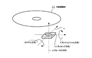
先ず、本発明によるチルト制御方法の説明に先立って、図1を参照して、本発明による光学ピックアップ装置を備えた光記録再生装置の一例の概略構成を説明する。この例においては、情報源1からの情報に基づき例えばディスク状の光記録媒体11に記録を行う場合の光照射態様の一例を示す。
図1に示すように、レーザーダイオード(LD)等より成る光源3から出射される光は、情報源1により情報信号に対応して変調され、また自動パワー制御手段(APC)2により出力が制御される。そしてこの出射光は、光学部41においてコリメーターレンズ4により平行光とされ、偏光ビームスプリッター6、ミラー7を介した後、1/4波長板8により円偏光化されてヘッド部42のレンズ91により光記録媒体11の記録面に入射される。
First, prior to the description of the tilt control method according to the present invention, a schematic configuration of an example of an optical recording / reproducing apparatus including the optical pickup device according to the present invention will be described with reference to FIG. In this example, an example of a light irradiation mode when recording is performed on, for example, a disk-shaped
As shown in FIG. 1, light emitted from a light source 3 comprising a laser diode (LD) or the like is modulated by an information source 1 in response to an information signal, and its output is controlled by an automatic power control means (APC) 2. Is done. The emitted light is converted into parallel light by the collimator lens 4 in the optical unit 41, passes through the polarizing beam splitter 6 and the mirror 7, and then circularly polarized by the quarter wavelength plate 8, and the
ヘッド部42は、駆動部43を構成するアクチュエーター10にレンズ91が設置されて構成される。光記録媒体11は、これを回転移動する例えば回転手段17より成る移動機構部47に保持され、光記録媒体11が回転軸18を中心軸として回転されると共に、図示しないが例えばヘッド部42側を光記録媒体11の記録面に沿って平行移動する水平移動機構との連動によって、ヘッド部42から照射される光が光記録媒体11の盤面に沿って例えばスパイラル状、同心円状の記録トラックに沿って走査される構成とする。
The
光記録媒体11から反射された光は、1/4波長板8を通り再び直線偏光になった後、偏光ビームスピリッター6により反射され、シリンドリカルレンズ5を介してフォトディテクタ12より成る検出部44にて検出される。フォトディテクタ12では、戻り光量が非点収差法、ナイフエッジ法等によって検出され、フォーカスエラー信号Efとして光記録媒体9の記録面とヘッド部42のレンズ91との距離を制御するサーボ、例えばフォーカスサーボ15に出力される。
The light reflected from the
そしてこのフォーカスサーボ15を含む第1の制御部45において、フォーカスエラー信号Efを非制御量として、フォーカスサーボ15によりフォーカス制御信号Sfが生成され、レンズアクチュエーター10にフィードバックされる。その結果、レンズ91と光記録媒体11との距離は一定に保持される。なお、フォーカスサーボ構成としては、位相補償フィルター、PID(Proportional Integral Differential)コントローラ等を用いることができる。
In the first control unit 45 including the
一方、チルトを制御する第2の制御部46においては、後述するチルトセンサー90により、レンズ91と光記録媒体11との傾き(チルト)量が検出され、チルトエラーEtとしてチルトサーボ16に入力される。そして、チルト制御信号Stとして後述するチルトアクチュエーター9に入力される。その結果、レンズ91と光記録媒体11との傾き(チルト)が補正される。なお、チルトサーボ構成としては、位相補償フィルター、PIDコントローラ等が適用可能である。
On the other hand, in the second control unit 46 for controlling the tilt, the
図2は、本発明による光学ピックアップ装置を有する光記録再生装置の一例の概略構成図を示し、この場合再生を行う場合の光照射態様を示す。図2において、図1と対応する部分には、同一符号を付して重複説明を省略する。この場合、反射戻り光をビームスピリッター19により分割し、一部をフォトディテクタ20で検出する点が異なる。フォトディテクタ20は、RF信号帯域を有し、その出力が再生RF信号となる。
FIG. 2 shows a schematic configuration diagram of an example of an optical recording / reproducing apparatus having an optical pickup device according to the present invention, and shows a light irradiation mode in the case of reproducing in this case. In FIG. 2, parts corresponding to those in FIG. In this case, the difference is that the reflected return light is divided by the
ここで、図3に示すように、ディスク状の光記録媒体9に対し、破線x、y及びzをそれぞれトラッキング方向、トラックの延長する例えば円周方向、光記録媒体11とヘッド部42との距離を調整するいわゆるフォーカス方向とすると、ラジアル方向及びタンジェンシャル方向のチルトは、矢印r及びtで示すように、それぞれ破線x及びyを回転軸とする回転方向の傾きである。
Here, as shown in FIG. 3, with respect to the disc-shaped
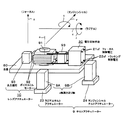
図4は、本発明の光学ピックアップ装置の一例における要部の概略構成を示す。この場合、ヘッド部のレンズ91は、台座80上に配置される例えばボイスコイルモーター92及び永久磁石93より成る従来の光記録再生装置において用いられる通常の2軸構成のレンズアクチュエーター10によって、図4において矢印x及びzで示す光記録媒体のラジアル方向(トラッキング方向)及びフォーカス方向に駆動可能とされる。
このような構成において、フォーカス制御電圧Vf21ないし、トラッキング制御電圧Vtをボイスコイルモーター92にそれぞれ印加することで、フォーカス軸ないしラジアル軸方向に対物レンズ91を移動させる。
FIG. 4 shows a schematic configuration of a main part in an example of the optical pickup device of the present invention. In this case, the
In such a configuration, the
そして本発明による光学ピックアップ装置では、チルトアクチュエーター9が、ヘッド部のレンズ91の光軸cに対して、略光記録媒体のラジアル方向(x軸方向)及びタンジェンシャル方向(y軸方向)に延長する位置に設けられる。
図示の例においては、y軸方向に延長する位置及びx軸方向に延長する位置にラジアルチルトアクチュエーター23及びタンジェンシャルチルトアクチュエーター24を設けた場合を示す。図5は、これら各アクチュエーター23及び24の台座80上の配置位置を簡略化して示した概略構成図である。例えばこれらのアクチュエーター23及び24をステッピングモーターより構成し、それぞれz軸方向に延長するz軸高さ送り軸9A及び9Bを介して台座80のそれぞれ破線yで示すタンジェンシャル軸及び破線xで示すラジアル軸方向に光軸cから延長する位置に固定されて成る。
In the optical pickup device according to the present invention, the
In the illustrated example, a case is shown in which a
そしてこのような構成において、これらチルトアクチュエーター9の例えばラジアルチルトアクチュエーター23に電圧を印加することによってラジアル方向に、またタンジェンシャルチルトアクチュエーター24に電圧を印加することによってタンジェンシャル方向にそれぞれ台座80を傾けて、結果的に従来の2軸構成のレンズアクチュエーターごと台座80自体を移動させてレンズすなわちヘッド部を傾け、これにより両方向のチルト制御を行うことができる。
In such a configuration, the
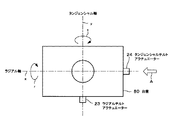
図6は、このような構成によるヘッド部の台座80を下面から見た概略構成図である。つまり、タンジェンシャル方向に台座80をチルトさせるためのタンジェンシャルチルトアクチュエーター23と、ラジアル方向に台座80をチルトさせるためのラジアルチルトアクチュエーター24とが、互いにヘッド部の光軸に対し略直交する位置に設置されている。
FIG. 6 is a schematic configuration diagram of the
なお、このチルトアクチュエーター9として、上述したようにステッピングモーターを用いる場合は、数nm程度から10μmを超える比較的広いレンジでの制御が可能となる。また、印加電圧も5V程度と比較的低電圧であり、消費電力の増大化を抑制することができる。
また、その例えばチルトアクチュエーター9として圧電素子を用いることもできる。この場合は、一般的にサーボ帯域が数十kHzまで対応可能であり、しかもカットオフ周波数まで位相遅れがないという特徴がある。このため、高速かつ微小な位置制御が可能である。
Note that when a stepping motor is used as the
For example, a piezoelectric element can be used as the
したがって、例えば光記録媒体11がディスク状である場合は、半径方向にμm単位でチルトが生じるいわゆるディスク垂れに対応するために、ラジアルチルトアクチュエーターとしてステッピングモーターを用いて、タンジェンシャルチルトアクチュエーターとしては、高速かつ微小な位置制御が可能な圧電素子を用いることによって、より実用的なチルト制御を行うことが可能となる。
Therefore, for example, when the
図7A及びBは、上述の本発明光学ピックアップ装置において用いることが可能な一般的なチルトセンサーの一例の検出態様を示した概略構成図である。図7Aに示すように、チルトセンサー90は、LED等より成る発光手段5とフォトディテクタ(PD)等よりなる受光手段26とから成る。発光手段25からの光は光記録媒体11を照射し、戻り光を受光手段PD26で受ける。
7A and 7B are schematic configuration diagrams showing a detection mode of an example of a general tilt sensor that can be used in the above-described optical pickup device of the present invention. As shown in FIG. 7A, the
図7Bは、チルトセンサー90の一例を上面から見た概略構成図である。受光手段26は例えば2分割PD(A及びB)より成り、発光手段25に対して並置配列されている。光記録媒体11のチルトセンサー90に対する傾きに対して受光手段26のA部とB部の受光光量が異なる。そこで、A部とB部の差分をとることにより、光記録媒体11のチルトセンサー90に対する傾き量がわかることになる。
FIG. 7B is a schematic configuration diagram illustrating an example of the
図8は、このような構成によるチルトセンサー90の一例の出力波形図である。図8に示すように、出力波形が例えば略線形となるチルトエラー検出範囲内であれば、チルト角と比例した電圧が得られ、この電圧をチルトアクチュエーター9に入力することでチルト角を制御することが可能である。
FIG. 8 is an output waveform diagram of an example of the
なお、このようなチルトセンサーによりチルトを検出する方法以外にも、プッシュプル法で検出したトラッキングエラーのDCオフセットにより検出する方法など、各種のチルト検出方法を用いることができる。 In addition to the method of detecting the tilt by such a tilt sensor, various tilt detection methods such as a method of detecting by the DC offset of the tracking error detected by the push-pull method can be used.
このようにして検出されたチルト量を、図4及び図5において説明したラジアルチルトアクチュエーター23及びタンジェンシャルチルトアクチュエーター24にフィードバックすることで、対物レンズ91と光記録媒体11とのチルト量を略ゼロに補正することができる。
図9A〜Cにおいては、図6において矢印Aで示すタンジェンシャルチルトアクチュエーター24のラジアル方向の延長方向から台座を見た場合におけるラジアル方向のチルト角がそれぞれ0、−及び+の場合の側面図を示す。
The tilt amount detected in this way is fed back to the
9A to 9C are side views when the tilt angles in the radial direction when the pedestal is viewed from the radial extension direction of the
図9Aに示すように、チルト角がゼロの場合は、台座80が略光記録媒体11の記録面に対し略平行とされる。このとき、チルトアクチュエーター9は、ラジアルチルトアクチュエーター23及びタンジェンシャルチルトアクチュエーター24の高さが共にdであるとする。なお、矢印x及びyは、それぞれラジアル軸及びタンジェンシャル軸、また一点鎖線vは、台座80上のレンズアクチュエーター10に保持されるレンズ(図示せず)の中心位置から延長する台座80の垂線を示す。また、台座80の表面に沿う平面を一点鎖線hで示す。この場合、点Cは台座80のラジアルチルト補正方向に関する回転中心位置であり、この場合タンジェンシャルチルトアクチュエーター24の台座80への固定位置に略一致する。
As shown in FIG. 9A, when the tilt angle is zero, the
ここで、チルト角θ<0の場合は、図9Bに示すように、チルトアクチュエーター9の一方、この場合ラジアルチルトアクチュエーター23が、高さdからd+a(aは、検出されたチルト量に比例する補正量)となるように電圧印加されて変化し、レンズと光記録媒体11とのチルトがゼロになるように補正される。このとき、台座80は点Cを中心軸として角度θ傾く。レンズアクチュエーター10のフォーカス方向の垂線を一点鎖線v1で示す。
Here, when the tilt angle θ <0, as shown in FIG. 9B, one of the
また逆に、チルト角θ>0の場合は、図9Cに示すように、チルトアクチュエーター23が高さdからd−b(bは、検出されたチルト量に比例する補正量)に変化し、レンズと光記録媒体11とのチルトがゼロになるように補正される。なお、タンジェンシャル方向のチルトが生じた場合においても、同様に、タンジェンシャルチルトアクチュエーター24が動作することはいうまでもない。この場合は、その回転中心位置は、ラジアルチルトアクチュエーター23の台座80への固定位置に略一致する。
また、例えば一方のチルトアクチュエーター9の長さを固定として、他方のみを伸縮させる構成としてもよい。
Conversely, when the tilt angle θ> 0, as shown in FIG. 9C, the
Further, for example, the length of one
次に、本発明による光学ピックアップ装置において、台座を第1及び第2の台座81及び82より構成する場合について、図10の要部の概略構成図を参照して説明する。図10において、図5と対応する部分には同一符号を付して重複説明を省略する。
この例においては、レンズ91の光軸からそれぞれ光記録媒体のタンジェンシャル方向及びラジアル方向に延長する位置に、第1及び第2のラジアルチルトアクチュエーター23A及び23B、第1及び第2のタンジェンシャルチルトアクチュエーター24A及び24Bを設ける場合を示す。
Next, in the optical pickup device according to the present invention, the case where the pedestal is constituted by the first and
In this example, the first and second
第1のラジアルチルトアクチュエーター23A及び第1のタンジェンシャルチルトアクチュエーター24Aは、第1の台座81の下部に配置して、第2のラジアルチルトアクチュエーター23B及び第2のタンジェンシャルチルトアクチュエーター24Bは、第1及び第2の台座81及び82の間に設ける構成とする。
そして、例えば第1のチルトアクチュエーター23A及び第1のタンジェンシャルチルトアクチュエーター24Aをステッピングモーターより構成し、第2のチルトアクチュエーター23B及び第2のタンジェンシャルチルトアクチュエーター24Bを圧電素子で構成することができる。
The first
For example, the
この場合、例えばステッピングモーターより成る各チルトアクチュエーター23A及び24Aによってチルト制御の粗調整を行い、圧電素子より成るチルトアクチュエーター23B及び24Bによってチルト制御の微調整を行うことができる。
このように、2種類のアクチュエーターを用いることで、より精度良くチルト角に対応した制御を行うと共に、無駄な消費電力を抑制し、より効率良くチルト制御を行うことが可能となる。
In this case, for example, the tilt control can be roughly adjusted by the
In this way, by using two types of actuators, it is possible to perform control corresponding to the tilt angle with higher accuracy, suppress unnecessary power consumption, and perform tilt control more efficiently.
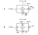
また、このように複数の種類のアクチュエーターを用いる場合の台座下面から見た配置例を図11A及びBの各概略構成図に示す。
図11Aに示す例は、図10において説明した例と同様に、ラジアルチルトアクチュエーター23A及び23Bを、一点鎖線yで示すタンジェンシャル軸延長方向の同一方向に、またタンジェンシャルチルトアクチュエーター24A及び24Bを一点鎖線xで示すラジアル軸延長方向の同一方向に配置した場合であるが、図11Bに示すように、各軸の延長方向の逆方向に各アクチュエーター23A及び23B、24A及び24Bを配置しても同様に精度良くチルト制御を行うことができる。
In addition, an arrangement example viewed from the bottom surface of the pedestal when a plurality of types of actuators are used is shown in each schematic configuration diagram of FIGS. 11A and 11B.
In the example shown in FIG. 11A, the
また、図12に同様に台座の仮面から見た配置例の概略構成を示すように、図11Aにおいて説明した例と同様に各チルトアクチュエーター23A及び23B、24A及び24Bを配置するとともに、それぞれ一点鎖線x及びyで示す各軸の延長する逆方向に、それぞれ支点となるピボット25〜28を配置する構成としてもよい。この場合は、台座を4点で支えることからより安定させることができる。
Similarly to FIG. 11A, the
以上説明したように、本発明によれば、ラジアル軸及びタンジェンシャル軸の延長方向にチルトアクチュエーターを配置することによって、より簡易な構成でヘッド部42のレンズ91と光記録媒体11とのチルト角を補正して、精度良くチルト制御を行うことができる。
チルトアクチュエーターとしてステッピングモーターを用いることによって、数nm程度から10μmを超える比較的幅広い範囲でのチルト制御が可能となり、また消費電力の増大化を抑制することができる。
ステッピングモーターに加えて圧電素子より成るチルトアクチュエーターを併用して粗調整及び微調整を行う構成とすることによって、タンジェンシャル及びラジアル両方向のチルトをきめ細かく、精度良く制御することができる。通常用いるレンズをトラッキング方向及びフォーカス方向に駆動する2軸アクチュエーターは、従来構成のままで特に変更は必要なく、この2軸アクチュエーターとは独立して設置されたチルトアクチュエーターにより、チルトを補正することが可能となる。
As described above, according to the present invention, the tilt angle between the
By using a stepping motor as a tilt actuator, tilt control in a relatively wide range exceeding several nanometers to over 10 μm is possible, and an increase in power consumption can be suppressed.
By using a tilt actuator composed of a piezoelectric element in addition to a stepping motor to perform coarse adjustment and fine adjustment, tilt in both tangential and radial directions can be finely and accurately controlled. The biaxial actuator that drives the normally used lens in the tracking direction and the focus direction does not need to be changed with the conventional configuration, and the tilt can be corrected by the tilt actuator installed independently of this biaxial actuator. It becomes possible.
なお、本発明は以上説明した実施の形態の例には限定されるものではなく、例えばチルトアクチュエーターとして、上述のステッピングモーター、圧電素子以外のアクチュエーターを用いるなど、種々の変形が可能である。
例えば、上述の例においては、通常の光記録、光磁気記録などによって光記録媒体に記録及び/又は再生を行う場合を説明したが、その他、例えば近接場光を用いて光記録媒体に記録及び/又は再生を行う場合に本発明を適用することもできる。
この場合は、SIL(ソリッドイマルジョンレンズ)、SIM(ソリッドイマルジョンミラー)等の開口数の大なるレンズを光記録媒体の記録面に波長の略1/4以下程度の微小間隔(ギャップ)をもって近接させるものであり、例えば上述の図1及び図2において説明した例において、第1の制御部に、フォーカスサーボではなくギャップサーボを設け、全反射戻り光量の変化を検出してギャップ制御信号を出力して、駆動部においてギャップを制御する構成とし得る。このとき、チルト検出方法としては、例えば光記録媒体に複数の光を照射して、その反射戻り光量の差分からチルトを検出する方法を用いることも可能である。
The present invention is not limited to the embodiments described above, and various modifications are possible, for example, using a stepping motor or an actuator other than a piezoelectric element as the tilt actuator.
For example, in the above-described example, the case where recording and / or reproduction is performed on an optical recording medium by normal optical recording, magneto-optical recording, or the like has been described. The present invention can also be applied when performing reproduction.
In this case, a lens with a large numerical aperture, such as SIL (solid immersion lens), SIM (solid immersion mirror), etc. is provided on the recording surface of the optical recording medium with a minute gap (gap) of about 1/4 or less of the wavelength. For example, in the example described with reference to FIGS. 1 and 2, the first control unit is provided with a gap servo instead of the focus servo, and a change in the total reflected return light amount is detected to generate a gap control signal. The gap may be controlled in the drive unit. At this time, as a tilt detection method, for example, it is also possible to use a method of irradiating a plurality of lights on an optical recording medium and detecting the tilt from the difference in the amount of reflected return light.
このように、近接場光を用いて光記録及び/又は再生を行う光学ピックアップ装置、光記録再生装置に本発明を適用する場合は、通常の光記録及び/又は再生を行う場合におけるレンズの焦点深度に起因する不感帯がなく、距離に対してリニアに制御を行うことができ、より精度良くチルト制御を行うことができる。本発明を適用して、上述したように、例えばステッピングモーターによる粗調整と圧電素子による特にタンジェンシャル方向のチルト制御の微調整を行うことによって、より精度よいチルト補正が可能となり、より安定した記録再生を行うことが可能となる。 As described above, when the present invention is applied to an optical pickup device that performs optical recording and / or reproduction using near-field light and an optical recording and reproduction device, the focal point of the lens when performing normal optical recording and / or reproduction. There is no dead zone due to the depth, control can be performed linearly with respect to the distance, and tilt control can be performed with higher accuracy. By applying the present invention, as described above, for example, coarse adjustment by a stepping motor and fine adjustment of tilt control, particularly in the tangential direction, by a piezoelectric element enable more accurate tilt correction and more stable recording. Playback can be performed.
特に、近接場光を用いる場合に限らず高密度記録又はその再生を行う光記録再生装置において、従来は精度良くチルトを制御されていなかったタンジェンシャル方向のチルト制御を確実に精度良く行うことができることから、より良好な記録再生特性をもって高密度記録再生を行うことが可能となる。
また、その他本発明は、上述の例に限定されることなく、本発明構成を逸脱しない範囲において、種々の変形、変更が可能であることはいうまでもない。
In particular, in an optical recording / reproducing apparatus that performs high-density recording or reproduction without being limited to the case of using near-field light, tilt control in the tangential direction, which has not been controlled with high accuracy in the past, can be performed with high accuracy. Therefore, high-density recording / reproduction can be performed with better recording / reproduction characteristics.
In addition, the present invention is not limited to the above examples, and it goes without saying that various modifications and changes can be made without departing from the configuration of the present invention.
1.情報源、2.パワー制御手段、3.光源、4.コリメーターレンズ、5.グレーティング、6.偏光ビームスプリッター、7.ミラー、8.1/4波長板、9.チルトアクチュエーター、10.レンズアクチュエーター、11.光記録媒体、12.フォトディテクタ、15.フォーカスサーボ、16.チルトサーボ、17.回転手段、18.回転軸、20.電圧印加手段、21vf.フォーカス制御電圧、22vf.トラッキング制御電圧、23.ラジアルチルトアクチュエーター、24.タンジェンシャルチルトアクチュエーター、41.光学部、42.ヘッド部、43.駆動部、44.光検出部、45.第1の制御部、46.第2の制御部、47.移動機構部、80.台座、90.チルトセンサー、91.レンズ、92.ボイスコイルモーター、93.永久磁石 1. Information source, 2. 2. power control means; Light source, 4. 4. collimator lens, Grating, 6. 6. polarization beam splitter; 8. mirror, 8.1 / 4 wave plate, 9. 9. Tilt actuator, 10. Lens actuator, Optical recording medium, 12. Photodetector, 15. Focus servo, 16. Tilt servo, 17. Rotating means, 18. Rotation axis, 20. Voltage applying means, 21 vf. Focus control voltage, 22 vf. Tracking control voltage, 23. Radial tilt actuator, 24. Tangential tilt actuator, 41. Optical section, 42. Head part, 43. Drive unit, 44. Light detector, 45. First control unit, 46. Second control unit, 47. Moving mechanism section, 80. Pedestal, 90. Tilt sensor, 91. Lens, 92. Voice coil motor, 93. permanent magnet
Claims (9)
前記光記録媒体の前記記録面に対する前記ヘッド部の前記記録面との距離を制御する第1の制御部を有するとともに、
前記光記録媒体の傾きに対応して前記ヘッド部を傾ける第2の制御部を具備し、
前記第2の制御部の前記ヘッド部を保持する台座には、前記ヘッド部の光軸に対して前記光記録媒体の略ラジアル方向及びタンジェンシャル方向に延長する位置にそれぞれチルトアクチュエーターが設けられて成る
ことを特徴とする光学ピックアップ装置。 An optical pickup device having a head unit for irradiating light from a light source onto a recording surface of an optical recording medium,
A first control unit that controls a distance between the recording surface of the head unit and the recording surface of the optical recording medium;
A second control unit for tilting the head unit corresponding to the tilt of the optical recording medium;
A tilt actuator is provided at a position that extends in a substantially radial direction and a tangential direction of the optical recording medium with respect to the optical axis of the head unit, on a base that holds the head unit of the second control unit. An optical pickup device comprising:
ことを特徴とする請求項1記載の光学ピックアップ装置。 2. The optical pickup device according to claim 1, wherein at least one of the tilt actuators comprises a stepping motor.
ことを特徴とする請求項1記載の光学ピックアップ装置。 2. The optical pickup device according to claim 1, wherein at least one of the tilt actuators comprises a piezoelectric element.
ことを特徴とする請求項2記載の光学ピックアップ装置。 3. The optical pickup device according to claim 2, wherein at least one of the tilt actuators comprises a piezoelectric element.
前記第1の台座の、前記ヘッド部の光軸に対して前記光記録媒体の少なくとも略ラジアル方向に延長する位置に、ステッピングモーターより成るチルトアクチュエーターが設けられて成り、
前記第2の台座の、前記ヘッド部の光軸に対して前記光記録媒体の少なくとも略タンジェンシャル方向に延長する位置に、圧電素子より成るチルトアクチュエーターが設けられて成る
ことを特徴とする請求項1記載の光学ピックアップ装置。 The pedestal comprises first and second pedestals;
A tilt actuator composed of a stepping motor is provided at a position of the first pedestal that extends at least in a substantially radial direction of the optical recording medium with respect to the optical axis of the head portion.
The tilt actuator made of a piezoelectric element is provided at a position of the second pedestal extending at least in a substantially tangential direction of the optical recording medium with respect to the optical axis of the head portion. The optical pickup device according to 1.
光記録媒体に対向して配置され、前記光源から出射された光を前記光記録媒体に集光させるヘッド部と、
前記光記録媒体と前記ヘッド部とを相対的に移動させる移動機構部と、
前記ヘッド部と前記光記録媒体との距離を一定に保持する駆動部と、
前記光記録媒体の記録面に対する前記ヘッド部のチルトを可変するチルトアクチュエーターと、
前記記録面に対する前記ヘッド部との距離を一定に保持するように前記駆動部を制御する第1の制御部と、
前記記録面に対する前記ヘッド部のチルトを補正するように前記チルトアクチュエーターを制御する第2の制御部とを有し、
前記チルトアクチュエーターが、前記ヘッド部の光軸に対し前記光記録媒体の略ラジアル方向及びタンジェンシャル方向に延長する位置に設けられて成る
ことを特徴とする光記録再生装置。 A light source;
A head unit disposed opposite to the optical recording medium and condensing the light emitted from the light source onto the optical recording medium;
A moving mechanism that relatively moves the optical recording medium and the head; and
A drive unit that maintains a constant distance between the head unit and the optical recording medium;
A tilt actuator that varies the tilt of the head unit with respect to the recording surface of the optical recording medium;
A first control unit that controls the drive unit to maintain a constant distance from the recording unit to the head unit;
A second control unit that controls the tilt actuator to correct the tilt of the head unit with respect to the recording surface;
An optical recording / reproducing apparatus, wherein the tilt actuator is provided at a position extending in a substantially radial direction and a tangential direction of the optical recording medium with respect to an optical axis of the head portion.
ことを特徴とする請求項6記載の光記録再生装置。 7. The optical recording / reproducing apparatus according to claim 6, wherein at least one of the tilt actuators comprises a stepping motor.
前記光記録媒体に対向して前記ヘッド部を保持する台座には、前記ヘッド部の光軸に対して前記光記録媒体の略ラジアル方向及びタンジェンシャル方向に延長する位置にそれぞれチルトアクチュエーターを設け、
前記ラジアル方向又はタンジェンシャル方向の少なくともどちらか一方のチルトアクチュエーターを駆動することによって、前記ヘッド部の前記光記録媒体に対するチルトを制御する
ことを特徴とするチルト制御方法。 A tilt control method for controlling the tilt of the head unit that irradiates the recording surface of an optical recording medium with light from a light source with respect to the optical recording medium,
A pedestal that holds the head portion facing the optical recording medium is provided with a tilt actuator at a position extending in a substantially radial direction and a tangential direction of the optical recording medium with respect to the optical axis of the head portion,
A tilt control method, wherein the tilt of the head unit with respect to the optical recording medium is controlled by driving at least one tilt actuator in the radial direction or the tangential direction.
前記光記録媒体の略タンジェンシャル方向に延長する位置に少なくとも圧電素子より成るチルトアクチュエーターを設けて、前記光記録媒体に対する前記ヘッド部のチルトを制御する
ことを特徴とする請求項8記載のチルト制御方法。 As the tilt actuator, a tilt actuator comprising at least a stepping motor is provided at a position extending in a substantially radial direction of the optical recording medium,
9. The tilt control according to claim 8, wherein a tilt actuator comprising at least a piezoelectric element is provided at a position extending in a substantially tangential direction of the optical recording medium to control the tilt of the head unit with respect to the optical recording medium. Method.
Priority Applications (1)
| Application Number | Priority Date | Filing Date | Title |
|---|---|---|---|
| JP2004148015A JP2005332449A (en) | 2004-05-18 | 2004-05-18 | Optical pickup device, optical recording and reproducing device and tilt control method |
Applications Claiming Priority (1)
| Application Number | Priority Date | Filing Date | Title |
|---|---|---|---|
| JP2004148015A JP2005332449A (en) | 2004-05-18 | 2004-05-18 | Optical pickup device, optical recording and reproducing device and tilt control method |
Publications (2)
| Publication Number | Publication Date |
|---|---|
| JP2005332449A true JP2005332449A (en) | 2005-12-02 |
| JP2005332449A5 JP2005332449A5 (en) | 2007-06-21 |
Family
ID=35487008
Family Applications (1)
| Application Number | Title | Priority Date | Filing Date |
|---|---|---|---|
| JP2004148015A Pending JP2005332449A (en) | 2004-05-18 | 2004-05-18 | Optical pickup device, optical recording and reproducing device and tilt control method |
Country Status (1)
| Country | Link |
|---|---|
| JP (1) | JP2005332449A (en) |
Cited By (16)
| Publication number | Priority date | Publication date | Assignee | Title |
|---|---|---|---|---|
| WO2007049893A1 (en) * | 2005-10-24 | 2007-05-03 | Lg Electronics Inc. | An apparatus and method for recording/reproducing data on/from a recording medium |
| US7646319B2 (en) | 2005-10-05 | 2010-01-12 | Lg Electronics Inc. | Method and apparatus for signal processing and encoding and decoding method, and apparatus therefor |
| US7672379B2 (en) | 2005-10-05 | 2010-03-02 | Lg Electronics Inc. | Audio signal processing, encoding, and decoding |
| US7680194B2 (en) | 2005-10-05 | 2010-03-16 | Lg Electronics Inc. | Method and apparatus for signal processing, encoding, and decoding |
| US7716043B2 (en) | 2005-10-24 | 2010-05-11 | Lg Electronics Inc. | Removing time delays in signal paths |
| US7752053B2 (en) | 2006-01-13 | 2010-07-06 | Lg Electronics Inc. | Audio signal processing using pilot based coding |
| US7751485B2 (en) | 2005-10-05 | 2010-07-06 | Lg Electronics Inc. | Signal processing using pilot based coding |
| US7761303B2 (en) | 2005-08-30 | 2010-07-20 | Lg Electronics Inc. | Slot position coding of TTT syntax of spatial audio coding application |
| US7788107B2 (en) | 2005-08-30 | 2010-08-31 | Lg Electronics Inc. | Method for decoding an audio signal |
| US7987097B2 (en) | 2005-08-30 | 2011-07-26 | Lg Electronics | Method for decoding an audio signal |
| US8073702B2 (en) | 2005-06-30 | 2011-12-06 | Lg Electronics Inc. | Apparatus for encoding and decoding audio signal and method thereof |
| US8082157B2 (en) | 2005-06-30 | 2011-12-20 | Lg Electronics Inc. | Apparatus for encoding and decoding audio signal and method thereof |
| US8090586B2 (en) | 2005-05-26 | 2012-01-03 | Lg Electronics Inc. | Method and apparatus for embedding spatial information and reproducing embedded signal for an audio signal |
| US8130623B2 (en) | 2008-05-23 | 2012-03-06 | Panasonic Corporation | Optical information recording and/or reproducing apparatus, optical information recording and/or reproducing method, optical information recording medium, and solid immersion lens |
| US8185403B2 (en) | 2005-06-30 | 2012-05-22 | Lg Electronics Inc. | Method and apparatus for encoding and decoding an audio signal |
| US8577483B2 (en) | 2005-08-30 | 2013-11-05 | Lg Electronics, Inc. | Method for decoding an audio signal |
Families Citing this family (2)
| Publication number | Priority date | Publication date | Assignee | Title |
|---|---|---|---|---|
| US7696907B2 (en) | 2005-10-05 | 2010-04-13 | Lg Electronics Inc. | Method and apparatus for signal processing and encoding and decoding method, and apparatus therefor |
| KR100857112B1 (en) | 2005-10-05 | 2008-09-05 | 엘지전자 주식회사 | Method and apparatus for signal processing and encoding and decoding method, and apparatus therefor |
-
2004
- 2004-05-18 JP JP2004148015A patent/JP2005332449A/en active Pending
Cited By (37)
| Publication number | Priority date | Publication date | Assignee | Title |
|---|---|---|---|---|
| US8214220B2 (en) | 2005-05-26 | 2012-07-03 | Lg Electronics Inc. | Method and apparatus for embedding spatial information and reproducing embedded signal for an audio signal |
| US8170883B2 (en) | 2005-05-26 | 2012-05-01 | Lg Electronics Inc. | Method and apparatus for embedding spatial information and reproducing embedded signal for an audio signal |
| US8150701B2 (en) | 2005-05-26 | 2012-04-03 | Lg Electronics Inc. | Method and apparatus for embedding spatial information and reproducing embedded signal for an audio signal |
| US8090586B2 (en) | 2005-05-26 | 2012-01-03 | Lg Electronics Inc. | Method and apparatus for embedding spatial information and reproducing embedded signal for an audio signal |
| US8073702B2 (en) | 2005-06-30 | 2011-12-06 | Lg Electronics Inc. | Apparatus for encoding and decoding audio signal and method thereof |
| US8494667B2 (en) | 2005-06-30 | 2013-07-23 | Lg Electronics Inc. | Apparatus for encoding and decoding audio signal and method thereof |
| US8214221B2 (en) | 2005-06-30 | 2012-07-03 | Lg Electronics Inc. | Method and apparatus for decoding an audio signal and identifying information included in the audio signal |
| US8185403B2 (en) | 2005-06-30 | 2012-05-22 | Lg Electronics Inc. | Method and apparatus for encoding and decoding an audio signal |
| US8082157B2 (en) | 2005-06-30 | 2011-12-20 | Lg Electronics Inc. | Apparatus for encoding and decoding audio signal and method thereof |
| US8103513B2 (en) | 2005-08-30 | 2012-01-24 | Lg Electronics Inc. | Slot position coding of syntax of spatial audio application |
| US7761303B2 (en) | 2005-08-30 | 2010-07-20 | Lg Electronics Inc. | Slot position coding of TTT syntax of spatial audio coding application |
| US7765104B2 (en) | 2005-08-30 | 2010-07-27 | Lg Electronics Inc. | Slot position coding of residual signals of spatial audio coding application |
| US7783494B2 (en) | 2005-08-30 | 2010-08-24 | Lg Electronics Inc. | Time slot position coding |
| US7788107B2 (en) | 2005-08-30 | 2010-08-31 | Lg Electronics Inc. | Method for decoding an audio signal |
| US7792668B2 (en) | 2005-08-30 | 2010-09-07 | Lg Electronics Inc. | Slot position coding for non-guided spatial audio coding |
| US8577483B2 (en) | 2005-08-30 | 2013-11-05 | Lg Electronics, Inc. | Method for decoding an audio signal |
| US7822616B2 (en) | 2005-08-30 | 2010-10-26 | Lg Electronics Inc. | Time slot position coding of multiple frame types |
| US7831435B2 (en) | 2005-08-30 | 2010-11-09 | Lg Electronics Inc. | Slot position coding of OTT syntax of spatial audio coding application |
| US8103514B2 (en) | 2005-08-30 | 2012-01-24 | Lg Electronics Inc. | Slot position coding of OTT syntax of spatial audio coding application |
| US7987097B2 (en) | 2005-08-30 | 2011-07-26 | Lg Electronics | Method for decoding an audio signal |
| US8060374B2 (en) | 2005-08-30 | 2011-11-15 | Lg Electronics Inc. | Slot position coding of residual signals of spatial audio coding application |
| US7684498B2 (en) | 2005-10-05 | 2010-03-23 | Lg Electronics Inc. | Signal processing using pilot based coding |
| US7646319B2 (en) | 2005-10-05 | 2010-01-12 | Lg Electronics Inc. | Method and apparatus for signal processing and encoding and decoding method, and apparatus therefor |
| US7751485B2 (en) | 2005-10-05 | 2010-07-06 | Lg Electronics Inc. | Signal processing using pilot based coding |
| US7672379B2 (en) | 2005-10-05 | 2010-03-02 | Lg Electronics Inc. | Audio signal processing, encoding, and decoding |
| US8068569B2 (en) | 2005-10-05 | 2011-11-29 | Lg Electronics, Inc. | Method and apparatus for signal processing and encoding and decoding |
| US7680194B2 (en) | 2005-10-05 | 2010-03-16 | Lg Electronics Inc. | Method and apparatus for signal processing, encoding, and decoding |
| US8095357B2 (en) | 2005-10-24 | 2012-01-10 | Lg Electronics Inc. | Removing time delays in signal paths |
| US7840401B2 (en) | 2005-10-24 | 2010-11-23 | Lg Electronics Inc. | Removing time delays in signal paths |
| US7742913B2 (en) | 2005-10-24 | 2010-06-22 | Lg Electronics Inc. | Removing time delays in signal paths |
| US7716043B2 (en) | 2005-10-24 | 2010-05-11 | Lg Electronics Inc. | Removing time delays in signal paths |
| WO2007049893A1 (en) * | 2005-10-24 | 2007-05-03 | Lg Electronics Inc. | An apparatus and method for recording/reproducing data on/from a recording medium |
| US8095358B2 (en) | 2005-10-24 | 2012-01-10 | Lg Electronics Inc. | Removing time delays in signal paths |
| US7761289B2 (en) | 2005-10-24 | 2010-07-20 | Lg Electronics Inc. | Removing time delays in signal paths |
| US7808866B2 (en) | 2005-10-24 | 2010-10-05 | Lg Electronics, Inc. | Apparatus and method for recording/reproducing data on/from a recording medium |
| US7752053B2 (en) | 2006-01-13 | 2010-07-06 | Lg Electronics Inc. | Audio signal processing using pilot based coding |
| US8130623B2 (en) | 2008-05-23 | 2012-03-06 | Panasonic Corporation | Optical information recording and/or reproducing apparatus, optical information recording and/or reproducing method, optical information recording medium, and solid immersion lens |
Similar Documents
| Publication | Publication Date | Title |
|---|---|---|
| JP2005332449A (en) | Optical pickup device, optical recording and reproducing device and tilt control method | |
| JPWO2005112012A1 (en) | Optical pickup and optical disk device | |
| JP2008084368A (en) | Objective lens actuator and optical pickup device having the same | |
| JP3943071B2 (en) | Compatible optical pickup device, optical recording / reproducing device employing the same, and actuator for compatible optical pickup device | |
| KR20090071493A (en) | Optical pickup apparatus, optical read/write apparatus, and gap control method | |
| US7957234B2 (en) | Optical pickup apparatus | |
| US20070297301A1 (en) | Method And Device For Automatic Disc Skew Correction | |
| JP2008097661A (en) | Optical pickup device | |
| JPH1069648A (en) | Optical pickup device and adjusting method thereof | |
| JPH10283644A (en) | Focus controller, its method and optical disk device | |
| US20050219986A1 (en) | Optical pickup adjusting optical disc, optical pickup adjusting device, and method | |
| JP4254740B2 (en) | Optical recording / reproducing method, optical pickup device, and optical recording / reproducing device | |
| KR100669984B1 (en) | Optical pick-up device | |
| JP3651138B2 (en) | Objective lens driving device for optical disc apparatus | |
| JP2004055071A (en) | Optical pickup device, method of manufacturing optical pickup device, and recording and reproducing device | |
| KR100683928B1 (en) | Optical Actuator and Method of Compensation Off-axis using piezoelectric element | |
| JPWO2014188540A1 (en) | Optical component positioning apparatus and optical recording apparatus using the same | |
| JPH0684179A (en) | Optical recording/reproduction device | |
| JPH0896380A (en) | Optical disk device | |
| JPH10302287A (en) | Driver and driving method for objective lens and recorder/player | |
| JPH0547901B2 (en) | ||
| JPH09270143A (en) | Optical disk device | |
| JP2001134975A (en) | Objective lens for optical disk | |
| JPH1097727A (en) | Objective lens driving device for optical disk device | |
| JP2006120216A (en) | Optical pickup and disk driving device equipped with same |
Legal Events
| Date | Code | Title | Description |
|---|---|---|---|
| A521 | Written amendment |
Free format text: JAPANESE INTERMEDIATE CODE: A523 Effective date: 20070507 |
|
| A621 | Written request for application examination |
Free format text: JAPANESE INTERMEDIATE CODE: A621 Effective date: 20070507 |
|
| A977 | Report on retrieval |
Free format text: JAPANESE INTERMEDIATE CODE: A971007 Effective date: 20090909 |
|
| A131 | Notification of reasons for refusal |
Effective date: 20091020 Free format text: JAPANESE INTERMEDIATE CODE: A131 |
|
| A02 | Decision of refusal |
Effective date: 20100309 Free format text: JAPANESE INTERMEDIATE CODE: A02 |