JP2005331561A - Optical device and projector - Google Patents
Optical device and projector Download PDFInfo
- Publication number
- JP2005331561A JP2005331561A JP2004147486A JP2004147486A JP2005331561A JP 2005331561 A JP2005331561 A JP 2005331561A JP 2004147486 A JP2004147486 A JP 2004147486A JP 2004147486 A JP2004147486 A JP 2004147486A JP 2005331561 A JP2005331561 A JP 2005331561A
- Authority
- JP
- Japan
- Prior art keywords
- optical device
- support
- lid
- electro
- optical
- Prior art date
- Legal status (The legal status is an assumption and is not a legal conclusion. Google has not performed a legal analysis and makes no representation as to the accuracy of the status listed.)
- Withdrawn
Links
Images


Abstract
Description
本発明は、光学装置、およびプロジェクタに関する。 The present invention relates to an optical device and a projector.
従来、光源から射出された光束を画像情報に応じて変調する複数の光変調装置と、変調された各色光を合成して光学像を形成する色合成光学装置と、形成された光学像を拡大投射する投射光学装置とを備えたプロジェクタが知られている。
このようなプロジェクタでは、より鮮明な投射画像を得るために、各光変調装置間での画素ずれ、投射光学装置からの距離のずれの発生を防止する必要があり、各光変調装置、色合成光学装置、および投射光学装置が一体化された構造が提案されている(例えば、特許文献1参照)。
特許文献1に記載のプロジェクタでは、色合成光学装置の上方側端面、下方側端面、光束射出側端面、およびこの光束射出側端面に対向する端面を囲うように箱形枠を取り付ける。そして、箱形枠の所定位置に投射光学装置および3つの光変調装置をそれぞれ固定することで、各光変調装置、色合成光学装置、および投射光学装置が一体化される。
また、上述した各光変調装置、色合成光学装置、および投射光学装置を一体化したユニットは、プロジェクタの外装筐体の底板上に配置されるベースプレートにねじ等の固定部材にて取り付けられ、該ベースプレートに対して投射光学装置の投射方向に着脱可能に構成されている。このため、より鮮明な投射画像を得ることができる構造となるとともに、メンテナンス機会の多い投射光学装置および各光変調装置を一括して取り外すことができメンテナンス性が良好な構造となる。
Conventionally, a plurality of light modulation devices that modulate a light beam emitted from a light source according to image information, a color combining optical device that combines the modulated color lights to form an optical image, and an enlarged optical image A projector having a projection optical device for projecting is known.
In such a projector, in order to obtain a clearer projected image, it is necessary to prevent the occurrence of pixel shift between each light modulation device and distance shift from the projection optical device. A structure in which an optical device and a projection optical device are integrated has been proposed (see, for example, Patent Document 1).
In the projector described in Patent Document 1, a box-shaped frame is attached so as to surround an upper end surface, a lower end surface, a light beam emission side end surface, and an end surface facing the light beam emission side end surface of the color synthesis optical device. Then, by fixing the projection optical device and the three light modulation devices at predetermined positions of the box-shaped frame, each light modulation device, the color synthesis optical device, and the projection optical device are integrated.
Further, a unit in which each of the light modulation device, the color synthesizing optical device, and the projection optical device described above is integrated is attached to a base plate disposed on the bottom plate of the exterior casing of the projector with a fixing member such as a screw. It is configured to be detachable from the base plate in the projection direction of the projection optical device. For this reason, while becoming a structure which can obtain a clearer projection image, a projection optical apparatus and each light modulation apparatus with many maintenance opportunities can be removed collectively, and it becomes a structure with favorable maintainability.
特許文献1に記載のプロジェクタでは、各光変調装置、色合成光学装置、および投射光学装置を一体化したユニットをベースプレートから取り外す場合には、ベースプレートに対してユニットを取り付けるねじ等の固定部材を外す必要がある。このため、光変調装置と他の光学部品との隙間にドライバ等を差し入れて固定部材を外す作業を実施しなければならず、メンテナンスや交換時の作業性を良好とする構造とは言い難い。 In the projector described in Patent Document 1, when a unit in which each light modulation device, color synthesis optical device, and projection optical device are integrated is removed from the base plate, a fixing member such as a screw for attaching the unit to the base plate is removed. There is a need. For this reason, an operation of removing a fixing member by inserting a driver or the like into the gap between the light modulation device and another optical component has to be performed, and it is difficult to say that the structure improves workability during maintenance and replacement.
本発明の目的は、複数の光変調装置および投射光学装置のメンテナンスや交換を容易に実施できる光学装置、およびプロジェクタを提供することにある。 An object of the present invention is to provide an optical device and a projector that can easily perform maintenance and replacement of a plurality of light modulation devices and projection optical devices.
本発明の光学装置は、光源から射出された光束を画像情報に応じて変調する複数の光変調装置、および前記複数の光変調装置で変調された光束を合成して光学像を形成する色合成光学装置が一体化された電気光学装置を含む複数の光学部品と、前記複数の光学部品を前記光源から射出された光束の照明光軸に対する所定位置に収納配置する光学部品用筐体と、前記電気光学装置で形成された光学像を拡大投射する投射光学装置とを備えた光学装置であって、前記光学部品用筐体は、容器状の部品収納部材と、前記部品収納部材の開口部分を閉塞する蓋状部材とで構成され、前記蓋状部材は、前記部品収納部材に対して着脱可能に取り付けられ、前記電気光学装置を載置固定する電気光学装置載置部、および前記電気光学装置載置部上に立設され前記投射光学装置を支持する投射光学装置支持部を有し、前記電気光学装置および前記投射光学装置を一体化する支持構造体を備え、前記支持構造体は、前記蓋状部材に対して着脱可能に取り付けられ、前記蓋状部材に装着された状態で前記電気光学装置および前記投射光学装置を前記部品収納部材に対して着脱可能とすることを特徴とする。 The optical device according to the present invention includes a plurality of light modulation devices that modulate a light beam emitted from a light source according to image information, and a color combination that combines the light beams modulated by the plurality of light modulation devices to form an optical image. A plurality of optical components including an electro-optical device in which an optical device is integrated; a housing for optical components that houses and arranges the plurality of optical components at predetermined positions with respect to an illumination optical axis of a light beam emitted from the light source; An optical device comprising a projection optical device for enlarging and projecting an optical image formed by an electro-optical device, wherein the optical component housing includes a container-shaped component storage member and an opening portion of the component storage member. An electro-optical device mounting portion that mounts and fixes the electro-optical device, and the electro-optical device is configured to be detachably attached to the component storage member. Standing on the mounting section A projection optical device supporting unit for supporting the projection optical device; and a support structure for integrating the electro-optical device and the projection optical device, wherein the support structure is detachable from the lid-like member The electro-optical device and the projection optical device can be attached to and detached from the component storage member while being attached to the lid-like member.
ここで、部品収納部材および蓋状部材の取付構造、蓋状部材および支持構造体の取付構造としては、例えば、以下の構造を採用できる。
例えば、ねじ等の螺合部材により各部材を接続する。
また、例えば、ばね等の付勢部材により各部材を接続する。
さらに、例えば、各部材に互いに係合可能とする係合構造をそれぞれ形成し、係合構造により各部材を接続する。
さらにまた、例えば、各部材のうち一方の部材に嵌合突起を形成し、他方の部材に嵌合孔を形成し、嵌合突起および嵌合孔を嵌合させることで各部材を接続する。
本発明によれば、部品収納部材から蓋状部材を取り外すことで、蓋状部材とともに支持構造体も光学装置から取り外すことができる。すなわち、部品収納部材から蓋状部材を取り外すことで、蓋状部材とともに電気光学装置および投射光学装置を光学装置から取り外すことができる。このため、従来のように光変調装置と他の光学部品との隙間にドライバ等を差し入れて固定部材を外す作業を実施する必要がなく、部品収納部材に対する蓋状部材の取付状態を解放することで、光学装置から電気光学装置および投射光学装置を取り外すことができる。したがって、複数の光変調装置および投射光学装置のメンテナンスや交換時の作業性を良好とする。
また、蓋状部材とともに電気光学装置および投射光学装置を光学装置から取り外すことができるので、複数の光変調装置および投射光学装置のメンテナンスや交換を実施する際、部品収納部材に収納される他の光学部品のメンテナンスや交換も同時に実施できる。
Here, as the attachment structure of the component storage member and the lid-like member and the attachment structure of the lid-like member and the support structure, for example, the following structures can be adopted.
For example, each member is connected by a screwing member such as a screw.
For example, each member is connected by a biasing member such as a spring.
Further, for example, each member is formed with an engaging structure that can be engaged with each other, and each member is connected by the engaging structure.
Furthermore, for example, a fitting protrusion is formed on one member among the members, a fitting hole is formed on the other member, and the fitting protrusion and the fitting hole are fitted to connect the members.
According to the present invention, the support structure can be removed from the optical device together with the lid-like member by removing the lid-like member from the component housing member. That is, by removing the lid member from the component housing member, the electro-optical device and the projection optical device can be removed from the optical device together with the lid member. For this reason, it is not necessary to insert a screwdriver or the like in the gap between the light modulation device and another optical component and perform the work of removing the fixing member as in the prior art, and the mounting state of the lid-like member on the component storage member is released. Thus, the electro-optical device and the projection optical device can be removed from the optical device. Therefore, the workability at the time of maintenance and replacement of the plurality of light modulation devices and the projection optical device is improved.
In addition, since the electro-optical device and the projection optical device can be detached from the optical device together with the lid-like member, when performing maintenance or replacement of the plurality of light modulation devices and the projection optical device, other components stored in the component storage member Optical parts can be maintained and replaced at the same time.
本発明の光学装置では、前記蓋状部材は、前記部品収納部材の開口部分を閉塞する蓋状部材本体と、前記蓋状部材本体の端部から前記部品収納部材側に向けて前記蓋状部材本体に直交するように延出形成され、前記電気光学装置が前記支持構造体の前記電気光学装置載置部に載置固定された状態で前記電気光学装置および前記電気光学装置載置部を前記投射光学装置の投射方向に挿通可能とする開口を有する枠状の支持構造体支持枠とで構成され、前記支持構造体は、前記電気光学装置および前記電気光学装置載置部を前記支持構造体支持枠の前記開口に挿通した状態で、前記投射光学装置支持部が前記支持構造体支持枠に当接し、前記投射光学装置支持部が前記支持構造体支持枠に対して着脱可能に取り付けられることが好ましい。
本発明によれば、投射光学装置支持部が蓋状部材の支持構造体支持枠に当接し、投射光学装置支持部が支持構造体支持枠に対して着脱可能に取り付けられるので、支持構造体支持枠により投射光学装置支持部の面外方向の移動が規制され、蓋状部材による支持構造体の支持状態を安定に維持できる。
In the optical device according to the aspect of the invention, the lid-shaped member includes a lid-shaped member main body that closes an opening of the component storage member, and the lid-shaped member from the end of the lid-shaped member main body toward the component storage member side. The electro-optical device and the electro-optical device mounting portion are formed so as to extend perpendicular to the main body, and the electro-optical device is mounted and fixed on the electro-optical device mounting portion of the support structure. A frame-shaped support structure support frame having an opening that can be inserted in the projection direction of the projection optical device, and the support structure includes the electro-optical device and the electro-optical device mounting portion. The projection optical device support portion is in contact with the support structure support frame while being inserted into the opening of the support frame, and the projection optical device support portion is detachably attached to the support structure support frame. Is preferred.
According to the present invention, the projection optical device support is in contact with the support structure support frame of the lid-like member, and the projection optical device support is detachably attached to the support structure support frame. The movement of the projection optical device support in the out-of-plane direction is restricted by the frame, and the support state of the support structure by the lid-like member can be stably maintained.
本発明の光学装置では、前記投射光学装置支持部の対向する側端部の対向する位置には、互いに離間する方向に延出する一対の起立片が形成され、前記蓋状部材は、前記部品収納部材の開口部分を閉塞する蓋状部材本体と、前記蓋状部材本体の端部における前記一対の起立片に対応する各位置から前記投射光学装置の投射方向に突出する一対の支持面を有する支持構造体支持部とで構成され、前記支持構造体は、前記一対の起立片が前記一対の支持面上に支持され、前記一対の起立片が前記一対の支持面に対して着脱可能に取り付けられることが好ましい。
本発明によれば、支持構造体の一対の起立片が支持構造体支持部の一対の支持面上に支持され、一対の起立片が一対の支持面に対して着脱可能に取り付けられるので、支持構造体を支持構造体支持部に設置する際には、一対の起立片を一対の支持面に載置するように設置すればよく、支持構造体支持部に対する支持構造体の設置作業を容易とする。
また、蓋状部材において、蓋状部材本体の端部から突出するように一対の支持面を形成するだけで支持構造体の取付構造を形成でき、蓋状部材の構造の簡素化を図れる。
In the optical device according to the aspect of the invention, a pair of upright pieces extending in a direction away from each other is formed at opposing positions of the opposing side end portions of the projection optical device support portion, and the lid-like member is the component. A lid-like member main body that closes the opening of the storage member; and a pair of support surfaces that project in the projection direction of the projection optical device from positions corresponding to the pair of upstanding pieces at the ends of the lid-like member main body. The support structure is configured such that the pair of upstanding pieces are supported on the pair of support surfaces, and the pair of upright pieces are detachably attached to the pair of support surfaces. It is preferred that
According to the present invention, the pair of upright pieces of the support structure are supported on the pair of support surfaces of the support structure support portion, and the pair of upright pieces are detachably attached to the pair of support surfaces. When installing the structure on the support structure support part, it is only necessary to install the pair of upright pieces so as to be placed on the pair of support surfaces, thereby facilitating the installation work of the support structure with respect to the support structure support part. To do.
Further, in the lid-like member, the attachment structure of the support structure can be formed only by forming a pair of support surfaces so as to protrude from the end portion of the lid-like member body, and the structure of the lid-like member can be simplified.
本発明の光学装置では、前記支持構造体支持部は、前記蓋状部材本体の端部における前記一対の起立片に対応する各位置から前記投射方向に突出し、各突出方向先端部分が前記部品収納部材側に向けて前記蓋状部材本体に直交するようにそれぞれ延出し、各延出方向先端部分が互いに接続する平面視コ字形状を有し、コ字状先端部分の外側面に前記一対の支持面が形成されるとともに、コ字状内側面が前記投射光学装置支持部の外周形状に対応して形成され、前記支持構造体を支持した状態でコ字状基端部分の内側面が前記投射光学装置支持部に当接することが好ましい。
本発明によれば、支持構造体支持部は、平面視コ字形状を有し、支持構造体を支持した状態でコ字状基端部分の内側面が投射光学装置支持部に当接するので、一対の支持面のみならず、コ字状基端部分の内側面にて支持構造体を支持できる。したがって、蓋状部材による支持構造体の支持状態を安定に維持できる。
In the optical device according to the aspect of the invention, the support structure support portion protrudes in the projection direction from each position corresponding to the pair of upright pieces at the end of the lid-like member main body, and each protruding direction front end portion stores the component. Each of the extension-like tip portions extends in a direction perpendicular to the lid-like member main body toward the member side, and has a U-shape in plan view in which the extension direction tip portions are connected to each other. A U-shaped inner side surface is formed corresponding to the outer peripheral shape of the projection optical device support portion, and the inner side surface of the U-shaped base end portion is in a state of supporting the support structure. It is preferable to contact the projection optical device support.
According to the present invention, the support structure support portion has a U-shape in plan view, and the inner surface of the U-shaped base end portion abuts against the projection optical device support portion in a state of supporting the support structure. The support structure can be supported not only by the pair of support surfaces but also by the inner surface of the U-shaped base end portion. Therefore, the support state of the support structure by the lid-like member can be stably maintained.
本発明のプロジェクタは、光源装置と、上述した光学装置と、前記光学装置を内部の所定位置に収納配置する外装筐体とを備えていることを特徴とする。
本発明によれば、プロジェクタは、上述した光学装置、および外装筐体を備えているので、上述した光学装置と同様の作用・効果を享受できる。
また、複数の光変調装置および投射光学装置のメンテナンスや交換を容易に実施できる光学装置を備えているので、プロジェクタの利便性の向上が図れる。
The projector according to the present invention includes a light source device, the above-described optical device, and an exterior housing that houses and arranges the optical device at a predetermined position inside.
According to the present invention, since the projector includes the above-described optical device and the exterior housing, the projector can enjoy the same operations and effects as the above-described optical device.
In addition, since the optical device that can easily perform maintenance and replacement of the plurality of light modulation devices and the projection optical device is provided, the convenience of the projector can be improved.
[1.第1実施形態]
以下、本発明の第1実施形態を図面に基づいて説明する。
〔1-1.プロジェクタの構成〕
図1は、プロジェクタ1の概略構成を模式的に示す図である。
プロジェクタ1は、光源から射出される光束を画像情報に応じて変調して光学像を形成し、形成した光学像をスクリーン上に拡大投射するものである。このプロジェクタ1は、外装筐体としての外装ケース2と、光学装置3とを備える。
なお、図1において、図示は省略するが、外装ケース2内において、光学装置3以外の空間には、プロジェクタ1の構成部材に電力を供給する電源ユニット、プロジェクタ1の構成部材を冷却する冷却ユニット、前記電源ユニット、前記冷却ユニットおよび光学装置3を制御する制御基板等が配置されるものとする。
[1. First embodiment]
Hereinafter, a first embodiment of the present invention will be described with reference to the drawings.
[1-1. Configuration of the projector]
FIG. 1 is a diagram schematically showing a schematic configuration of the projector 1.
The projector 1 modulates a light beam emitted from a light source according to image information to form an optical image, and enlarges and projects the formed optical image on a screen. The projector 1 includes an
Although not shown in FIG. 1, a power supply unit that supplies power to the constituent members of the projector 1 and a cooling unit that cools the constituent members of the projector 1 in a space other than the
外装ケース2は、合成樹脂等から構成され、光学装置3を内部に収納配置する全体略直方体状に形成されている。この外装ケース2は、図示は省略するが、プロジェクタ1の天面、前面、背面、および側面をそれぞれ構成するアッパーケースと、プロジェクタ1の底面、前面、側面、および背面をそれぞれ構成するロアーケースとで構成され、前記アッパーケースおよび前記ロアーケースは互いにねじ等で固定されている。
なお、外装ケース2は、合成樹脂製に限らず、その他の材料にて形成してもよく、例えば、金属等により構成してもよい。
また、この外装ケース2には、図1に示すように、光学装置3の後述する投射レンズの先端部分を露出する開口21が形成され、前記投射レンズから射出される光学像が開口21を介してスクリーン上に投射される。
The
The
Further, as shown in FIG. 1, an
光学装置3は、詳細については後述するが、光源から射出された光束を、光学的に処理して画像情報に対応して光学像(カラー画像)を形成し、形成した光学像を拡大投射する。この光学装置3は、図1に示すように、外装ケース2の背面に沿って延出するとともに、外装ケース2の側面に沿って延出する平面視略L字形状を有している。
As will be described in detail later, the
〔1-2.光学装置の構成〕
図2は、光学装置3の内部構造を模式的に示す平面図である。
光学装置3は、図2に示すように、インテグレータ照明光学系31と、色分離光学系32と、リレー光学系33と、電気光学装置34と、投射光学装置としての投射レンズ35と、支持構造体としてのヘッド体36と、光学部品用筐体37とを備える。
インテグレータ照明光学系31は、電気光学装置34を構成する後述する液晶パネルの画像形成領域を略均一に照明するための光学系である。このインテグレータ照明光学系31は、図2に示すように、光源装置311と、第1レンズアレイ312と、第2レンズアレイ313と、偏光変換素子314と、重畳レンズ315とを備える。
[1-2. Configuration of optical device]
FIG. 2 is a plan view schematically showing the internal structure of the
As shown in FIG. 2, the
The integrator illumination
光源装置311は、放射状の光線を射出する光源ランプ316と、この光源ランプ316から放射された放射光を反射するリフレクタ317とを備える。光源ランプ316としては、ハロゲンランプやメタルハライドランプ、高圧水銀ランプが多用される。また、リフレクタ317としては、図2では、放物面鏡を採用しているが、これに限らず、楕円面鏡で構成し、光束射出側に該楕円面鏡により反射された光束を平行光とする平行化凹レンズを採用した構成としてもよい。
第1レンズアレイ312は、光軸方向から見て略矩形状の輪郭を有する小レンズがマトリクス状に配列された構成を有している。各小レンズは、光源装置311から射出される光束を、複数の部分光束に分割している。
第2レンズアレイ313は、第1レンズアレイ312と略同様な構成を有しており、小レンズがマトリクス状に配列された構成を有している。この第2レンズアレイ313は、重畳レンズ315とともに、第1レンズアレイ312の各小レンズの像を電気光学装置34の後述する液晶パネル上に結像させる機能を有している。
The
The
The
偏光変換素子314は、第2レンズアレイ313と重畳レンズ315との間に配置され、第2レンズアレイ313からの光を略1種類の偏光光に変換するものである。
具体的に、偏光変換素子314によって略1種類の偏光光に変換された各部分光は、重畳レンズ315によって最終的に電気光学装置34の後述する液晶パネル上にほぼ重畳される。偏光光を変調するタイプの液晶パネルを用いたプロジェクタでは、1種類の偏光光しか利用できないため、ランダムな偏光光を発する光源装置311からの光の略半分を利用できない。このため、偏光変換素子314を用いることで、光源装置311からの射出光を略1種類の偏光光に変換し、電気光学装置34での光の利用効率を高めている。
The
Specifically, each partial light converted into substantially one type of polarized light by the
色分離光学系32は、図2に示すように、2枚のダイクロイックミラー321,322と、反射ミラー323とを備え、ダイクロイックミラー321,322によりインテグレータ照明光学系31から射出された複数の部分光束を、赤、緑、青の3色の色光に分離する機能を有している。
リレー光学系33は、図2に示すように、入射側レンズ331、リレーレンズ333、および反射ミラー332,334を備え、色分離光学系32で分離された赤色光を電気光学装置34の後述する赤色光用の液晶パネルまで導く機能を有している。
As shown in FIG. 2, the color separation
As shown in FIG. 2, the relay optical system 33 includes an
この際、色分離光学系32のダイクロイックミラー321では、インテグレータ照明光学系31から射出された光束の青色光成分が反射するとともに、赤色光成分と緑色光成分とが透過する。ダイクロイックミラー321によって反射した青色光は、反射ミラー323で反射し、フィールドレンズ318を通って電気光学装置34の後述する青色光用の液晶パネルに達する。このフィールドレンズ318は、第2レンズアレイ313から射出された各部分光側をその中心軸(主光線)に対して平行な光束に変換する。他の緑色光用、赤色光用の液晶パネルの光入射側に設けられたフィールドレンズ318も同様である。
At this time, the
ダイクロイックミラー321を透過した赤色光と緑色光のうちで、緑色光はダイクロイックミラー322によって反射し、フィールドレンズ318を通って電気光学装置34の後述する緑色光用の液晶パネルに達する。一方、赤色光はダイクロイックミラー322を透過してリレー光学系33を通り、さらにフィールドレンズ318を通って電気光学装置34の後述する赤色光用の液晶パネルに達する。なお、赤色光にリレー光学系33が用いられているのは、赤色光の光路の長さが他の色光の光路長さよりも長いため、光の発散等による光の利用効率の低下を防止するためである。すなわち、入射側レンズ331に入射した部分光束をそのまま、フィールドレンズ318に伝えるためである。
Of the red light and green light transmitted through the
電気光学装置34は、図2に示すように、3枚の光変調装置としての液晶パネル341(赤色光用の液晶パネルを341R、緑色光用の液晶パネルを341G、青色光用の液晶パネルを341Bとする)と、これら液晶パネル341の光束入射側および光束射出側にそれぞれ配置される入射側偏光板342および射出側偏光板343と、色合成光学装置としてのクロスダイクロイックプリズム344とを備える。そして、これらのうち、3枚の液晶パネル341、3つの射出側偏光板343、およびクロスダイクロイックプリズム344が一体化され、ここでは図示しない電気光学装置本体34Aを構成する。なお、本実施形態において、3枚の液晶パネル341、3つの射出側偏光板343、およびクロスダイクロイックプリズム344の他、入射側偏光板342も一体化する構成を採用してもよい。
As shown in FIG. 2, the electro-
入射側偏光板342は、偏光変換素子314で偏光方向が略一方向に揃えられた各色光が入射され、入射された光束のうち、偏光変換素子314で揃えられた光束の偏光軸と略同一方向の偏光光のみ透過させ、その他の光束を吸収するものである。この入射側偏光板342は、例えば、サファイアガラスまたは水晶等の透光性基板上に偏光膜が貼付された構成を有している。
液晶パネル341は、具体的な図示は省略するが、1対の透明なガラス基板に電気光学物質である液晶が密閉封入された構成を有し、図示しない制御基板から出力される駆動信号に応じて、前記液晶の配向状態が制御され、入射側偏光板342から射出された偏光光束の偏光方向を変調する。
The incident-side
Although not specifically illustrated, the
射出側偏光板343は、入射側偏光板342と略同様の構成であり、液晶パネル341から射出された光束のうち、入射側偏光板342における光束の透過軸と直交する偏光軸を有する光束のみ透過させ、その他の光束を吸収するものである。
クロスダイクロイックプリズム344は、射出側偏光板343から射出された色光毎に変調された光学像を合成してカラー画像を形成する光学素子である。このクロスダイクロイックプリズム344は、4つの直角プリズムを貼り合わせた平面視正方形状をなし、直角プリズム同士を貼り合わせた界面には、2つの誘電体多層膜が形成されている。これら誘電体多層膜は、液晶パネル341R,341Bから射出され射出側偏光板343を介した色光を反射し、液晶パネル341Gから射出され射出側偏光板343を介した色光を透過する。このようにして、各液晶パネル341R,341G,341Bにて変調された各色光が合成されてカラー画像が形成される。
The exit-side
The cross
投射レンズ35は、複数のレンズが組み合わされた組レンズとして構成される。そして、この投射レンズ35は、電気光学装置34にて形成された光学像(カラー画像)を図示しないスクリーン上に拡大投射する。
ヘッド体36は、例えばアルミニウム合金またはマグネシウム合金等の金属材料から構成され、後述する電気光学装置本体34Aおよび投射レンズ35を一体化するとともに、一体化したユニット(以下では、このユニットを便宜上、光学ユニットと呼称する)を光学部品用筐体37に対して取り付けるものである。なお、光学ユニットの詳細な構造については、後述する。また、電気光学装置本体34A、投射レンズ35、およびヘッド体36の詳細な構造についても、光学ユニットの詳細な構造を説明する際に同時に説明する。
光学部品用筐体37は、図2に示すように、内部に所定の照明光軸Aが設定され、上述した光学部品31〜33、および前記光学ユニットを照明光軸Aに対する所定位置に配置する。なお、この光学部品用筐体37の詳細な構造については、後述する。
The
The
As shown in FIG. 2, the
〔1-3.光学ユニットの構造〕
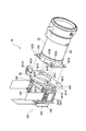
図3は、光学ユニット4の構造を示す分解斜視図である。
光学ユニット4は、上述したように、ヘッド体36により電気光学装置本体34Aおよび投射レンズ35が一体化されたユニットである。
[1-3. Structure of optical unit]
FIG. 3 is an exploded perspective view showing the structure of the
As described above, the
〔1-3-1.電気光学装置本体の構造〕
電気光学装置本体34Aは、上述したように、3つの液晶パネル341、3つの射出側偏光板343、およびクロスダイクロイックプリズム344が一体化されたものである。
3つの液晶パネル341は、図3に示すように、該液晶パネル341の画像形成領域に応じた開口を有する3つの保持部材345にそれぞれ保持され、該保持部材345を介してクロスダイクロイックプリズム344の各光束入射側端面にそれぞれ固定される。
また、3つの射出側偏光板343は、具体的な図示は省略するが、クロスダイクロイックプリズム344の各光束入射側端面にそれぞれ直接貼り付けられる。なお、クロスダイクロイックプリズム344の各光束入射側端面に直接貼り付ける構成の他、液晶パネル341と同様に、保持部材345に保持させる構成を採用してもよい。
以上のように、クロスダイクロイックプリズム344の各光束入射側端面にそれぞれ液晶パネル341および射出側偏光板343が固定されることで、電気光学装置本体34Aが組み立てられる。
[1-3-1. Electro-optical device structure]
As described above, the electro-
As shown in FIG. 3, the three
The three exit-side
As described above, the
〔1-3-2.投射レンズの構造〕
投射レンズ35の鏡筒351には、図3に示すように、光束入射側端部に、ヘッド体36に固定するための平面視略矩形状のフランジ352が取り付けられている。
このフランジ352には、図3に示すように、投射レンズ35をヘッド体36の所定位置に位置決めするための2つの位置決め用孔352A(図3では、1つのみの位置決め用孔352Aを示している)と、投射レンズ35をヘッド体36に固定するための4つの固定用孔352B(図3では、3つのみの固定用孔352Bを示している)とが形成されている。4つの固定用孔352Bは、フランジ352における四隅位置近傍に形成されている。また、2つの位置決め用孔352Aは、4つの固定用孔352Bのうち対角位置に形成された2つの固定用孔352B近傍に形成されている。
[1-3-2. Projection lens structure]
As shown in FIG. 3, a
As shown in FIG. 3, the
〔1-3-2.ヘッド体の構造〕
ヘッド体36は、図3に示すように、側面視略L字形状を有し、L字状の各端部がそれぞれ図示しない電気光学装置載置部、および投射光学装置支持部361として機能する。
前記電気光学装置載置部は、ヘッド体36のL字水平部分であり、平面視略矩形形状を有し、電気光学装置本体34Aを構成するクロスダイクロイックプリズム344の下面を支持する。この電気光学装置載置部は、平面視矩形状の外形寸法がクロスダイクロイックプリズム344の外形寸法と略同一、あるいは、若干小さく設定されている。
前記電気光学装置載置部において、クロスダイクロイックプリズム344と当接する上面の略中央部分には、球状の膨出部が形成されている。そして、前記膨出部にクロスダイクロイックプリズム344の下面を当接させることで、ヘッド体36に対するクロスダイクロイックプリズム344のあおり方向の位置調整が可能となる。
[1-3-2. Structure of the head body]
As shown in FIG. 3, the
The electro-optical device mounting portion is an L-shaped horizontal portion of the
In the electro-optical device mounting portion, a spherical bulging portion is formed at a substantially central portion of the upper surface that contacts the cross
投射光学装置支持部361は、図3に示すように、ヘッド体36のL字垂直部分であり、平面視略矩形形状を有し、投射レンズ35を支持するとともに、一体化した光学ユニット4を光学部品用筐体37に対して固定する部分である。
この投射光学装置支持部361において、光束射出側端面略中央部分には、図3に示すように、光束入射側に窪み、投射レンズ35のフランジ352の形状に対応した凹部361Aが形成されている。
この凹部361Aにおいて、矩形状の平面視略中央部分には、図3に示すように、光束透過用の開口361Bが形成されている。また、この開口361B近傍には、投射レンズ35のフランジ352に形成された位置決め用孔352Aおよび固定用孔352Bに対応して、2つの凸部361Cおよび4つのねじ孔361Dが形成されている。
また、この投射光学装置支持部361において、凹部361Aの近傍には、一体化した光学ユニット4を光学部品用筐体37に取り付けるための2つの位置決め用孔361Eと、4つの固定用孔361Fとが形成されている。4つの固定用孔361Fは、投射光学装置支持部361における四隅位置近傍に形成されている。また、2つの位置決め用孔361Eは、4つの固定用孔361Fのうち対角位置に形成された2つの固定用孔361F近傍に形成されている。
As shown in FIG. 3, the projection
In the projection optical
In the
In the projection optical
〔1-3-4.光学ユニットの組み立て構造〕
光学ユニット4を組み立てる際には、電気光学装置本体34Aをヘッド体36の図示しない電気光学装置載置部に載置固定するとともに、投射レンズ35をヘッド体36の投射光学装置支持部361に設置する。投射レンズ35をヘッド体36の投射光学装置支持部361に設置する際には、図3に示すように、フランジ352の位置決め用孔352Aが凸部361Cに嵌合するようにフランジ352を凹部361Aに設置する。また、フランジ352の固定用孔352Bを介して図示しないねじをねじ孔361Dに螺合することで、投射光学装置支持部361に投射レンズ35が支持固定され、光学ユニット4が組み立てられる。
[1-3-4. Assembly structure of optical unit]
When assembling the
〔1-4.光学部品用筐体の構造〕
図4は、光学部品用筐体37の構造を示す図である。具体的に、図4は、光学装置3の組み立て構造を示す分解斜視図である。
光学部品用筐体37は、図4に示すように、部品収納部材371と、蓋状部材372とで構成される。
部品収納部材371は、図4に示すように、光源装置311(図2)が収納される光源収納部371Aと、光源装置311(図2)を除く他の光学部品31,32,33(図2)が収納される部品収納部371Bとを備える。
光源収納部371Aは、具体的な図示は省略するが、下方側が開口し、前記開口を介して光源装置311(図2)が内部に収納配置される。また、部品収納部371Bとの接続部分には、光源装置311(図2)から射出される光束が通過するように開口が形成されている。
[1-4. Optical component housing structure]
FIG. 4 is a view showing the structure of the
As shown in FIG. 4, the
As shown in FIG. 4, the
Although the light
部品収納部371Bは、図4に示すように、上方側が開口し、一端側が光源収納部371Aと接続し、他端側が平面視略コ字状である容器状に形成され、この他端側の平面視コ字状内側部分に光学ユニット4を構成する電気光学装置本体34Aおよびヘッド体36の一部が配置される。
この部品収納部371Bにおいて、側面の内側面には、具体的な図示は省略するが、複数の溝部が形成され、該溝部に上述した光学部品312〜315,318,321〜323,331〜334,342を上方からスライド式に嵌め込まれる。
また、この部品収納部371Bにおいて、側面の外側面には、図4に示すように、蓋状部材372を取り付けるための複数のねじ孔371B1が形成されている。
As shown in FIG. 4, the
In this
Further, in the
蓋状部材372は、図4に示すように、蓋状部材本体372Aと、支持構造体支持枠372Bとで構成され、蓋状部材本体372Aおよび支持構造体支持枠372Bが一体化した構造を有している。
蓋状部材本体372Aは、図4に示すように、部品収納部材371における部品収納部371Bの上端側の開口部分を塞ぐように平面視略コ字状の板体から構成されている。
この蓋状部材本体372Aには、図4に示すように、部品収納部371Bのねじ孔371B1に対応して複数の固定用孔372A1が形成されている。
また、この蓋状部材本体372Aには、図4に示すように、蓋状部材372を部品収納部材371に設置した状態で、光学部品用筐体37内部に温められた空気が滞留しないように複数の開口部372A2が形成されている。
As shown in FIG. 4, the lid-
As shown in FIG. 4, the lid-like member
As shown in FIG. 4, the lid-like member
Further, as shown in FIG. 4, the lid-like member
支持構造体支持枠372Bは、光学ユニット4を支持する部分であり、図4に示すように、蓋状部材本体372Aのコ字状先端部分に位置し、該蓋状部材本体372Aの板面に直交する下方向に延出する平面視矩形状の板体から構成される。蓋状部材372を部品収納部材371に設置した状態では、支持構造体支持枠372Bは、部品収納部371Bの他端側の外側に配置される。
この支持構造体支持枠372Bにおいて、矩形状の平面視略中央部分には、図4に示すように、光束透過用の開口372B1が形成されている。また、この開口372B1近傍には、ヘッド体36における投射光学装置支持部361に形成された位置決め用孔361Eおよび固定用孔361Fに対応して、2つの凸部372B2および4つのねじ孔372B3が形成されている。
The support
In the support
〔1-5.光学ユニットおよび光学部品用筐体の組み立て構造〕
光学ユニット4および光学部品用筐体37を組み立てる際には、以下のように実施する。
光学ユニット4を構成する電気光学装置本体34Aおよびヘッド体36の図示しない電気光学装置載置部を、蓋状部材372の支持構造体支持枠372Bに形成された開口372B1に挿通する。また、支持構造体支持枠372Bの凸部372B2にヘッド体36の位置決め用孔361Eが嵌合するように、支持構造体支持枠372Bにヘッド体36の投射光学装置支持部361を当接させる。そして、ヘッド体36の固定用孔361Fを介してねじ38を支持構造体支持枠372Bのねじ孔372B3に螺合することで、光学ユニット4を蓋状部材372に固定する。
この後、蓋状部材372および光学ユニット4を部品収納部材371の上方側から、部品収納部材371の部品収納部371Bの開口部分を蓋状部材本体372Aにて覆うように設置する。そして、蓋状部材本体372Aの固定用孔372A1を介して図示しないねじを部品収納部371Bのねじ孔371B1に螺合することで、光学装置3が組み立てられる。
また、光学ユニット4を光学部品用筐体37から取り外す際には、上記と逆の手順にて実施される。
[1-5. Assembly structure of optical unit and optical component housing]
When assembling the
The electro-optical device mounting portion (not shown) of the electro-optical device
Thereafter, the lid-
Further, when removing the
上述した第1実施形態においては、光学装置3において、部品収納部材371から蓋状部材372を取り外すことで、蓋状部材372とともに光学ユニット4を取り外すことができる。このため、従来のように液晶パネル341と他の光学部品との隙間にドライバ等を差し入れてねじ等の固定部材を外す作業を実施する必要がなく、部品収納部材に対する蓋状部材372の取付状態を解放することで光学装置3から光学ユニット4を容易に取り外すことができる。したがって、液晶パネル341および投射レンズ35のメンテナンスや交換時の作業性を良好とする。
また、蓋状部材372とともに光学ユニット4を光学装置3から取り外すことができるので、液晶パネル341および投射レンズ35のメンテナンスや交換を実施する際、部品収納部材371に収納される他の光学部品312〜315,318,321〜323,331〜334,342のメンテナンスや交換も同時に実施できる。
In the first embodiment described above, in the
Further, since the
ここで、光学ユニット4は、ヘッド体36の投射光学装置支持部361が蓋状部材372の支持構造体支持枠372Bに当接し、投射光学装置支持部361が支持構造体支持枠372Bにねじ38により固定されるので、支持構造体支持枠372Bにより投射光学装置支持部361の面外方向の移動が規制され、蓋状部材372による光学ユニット4の支持状態を安定に維持できる。
そして、液晶パネル341および投射レンズ35のメンテナンスや交換を容易に実施できる光学装置3を備えているので、プロジェクタ1の利便性の向上が図れる。
Here, in the
Since the
[2.第2実施形態]
次に、本発明の第2実施形態を図面に基づいて説明する。
以下の説明では、前記第1実施形態と同様の構造および同一部材には同一符号を付して、その詳細な説明は省略または簡略化する。
本実施形態は、ヘッド体と光学部品用筐体における蓋状部材との接続構造が前記第1実施形態と異なる。すなわち、ヘッド体における投射光学装置支持部の構造、および蓋状部材の構造が前記第1実施形態と異なる。投射光学装置支持部および蓋状部材の構造以外は、前記第1実施形態と同様のものとする。
[2. Second embodiment]
Next, 2nd Embodiment of this invention is described based on drawing.
In the following description, the same structure and the same members as those in the first embodiment are denoted by the same reference numerals, and detailed description thereof is omitted or simplified.
This embodiment is different from the first embodiment in the connection structure between the head body and the lid-like member in the optical component casing. That is, the structure of the projection optical device support in the head body and the structure of the lid-like member are different from those in the first embodiment. Except for the structure of the projection optical device support and the lid-like member, it is the same as in the first embodiment.
〔2-1.投射光学装置支持部の構造〕
図5は、第2実施形態におけるヘッド体46の投射光学装置支持部461の構造を示す図である。
ヘッド体46の投射光学装置支持部461は、前記第1実施形態で説明した投射光学装置支持部361と同様に、図5に示すように、電気光学装置本体34Aおよび投射レンズ35を一体化して光学ユニット4Aを構成するとともに、該光学ユニット4Aを蓋状部材472(図6参照)に対して固定する部分である。
この投射光学装置支持部461において、光束射出側端面の略中央部分に位置する平面視略矩形領域は、投射レンズ35が取り付けられる領域であり、前記第1実施形態で説明した投射光学装置支持部361と同様に、図5に示すように、開口361B、2つの凸部361C、および4つのねじ孔361Dが形成されている。すなわち、光学ユニット4Aの組み立て構造は、前記第1実施形態で説明した光学ユニット4の組み立て構造と同様である。
[2-1. Projection optical device support structure]
FIG. 5 is a view showing the structure of the projection
Similar to the projection
In the projection optical
また、この投射光学装置支持部461において、左右方向両端縁の上方側の対向する位置には、図5に示すように、互いに離間する方向に延出し、光学ユニット4Aを蓋状部材472に取り付けるための一対の起立片461Aがそれぞれ形成されている。
これら起立片461Aは、下方側端面が略平面状に形成されており、該下方側端面が蓋状部材472の後述する支持構造体支持部の一対の支持面に当接する。
これら起立片461Aには、図5に示すように、上方側端面および下方側端面を貫通して、起立片461Aを蓋状部材472に固定するためのねじ孔461A1がそれぞれ形成されている。
Further, in the projection optical
These standing
As shown in FIG. 5, these standing
〔2-2.蓋状部材の構造〕
図6は、第2実施形態における光学部品用筐体47の構造を示す図である。具体的に、図6は、第2実施形態における光学装置3Aの組み立て構造を示す分解斜視図である。
蓋状部材472は、前記第1実施形態で説明した蓋状部材本体372Aの他、支持構造体支持部472Bを備える。
蓋状部材472の支持構造体支持部472Bは、図6に示すように、蓋状部材本体372Aのコ字状先端部分に突出するように設けられ、蓋状部材本体372Aのコ字状先端部分から該蓋状部材本体372Aの板面に直交する下方向にそれぞれ延出するとともに、各延出方向先端部分が互いに接続する平面視略コ字状に形成されている。蓋状部材472を部品収納部材371に設置した状態では、支持構造体支持部472Bは、部品収納部371Bの他端側の外側に配置される。
この支持構造体支持部472Bにおいて、コ字状先端部分の上端面は、図6に示すように、光学ユニット4Aを構成するヘッド体46の起立片461Aを載置可能に略平面状に形成され、起立片461Aを支持する支持面472B1となる。そして、この支持面472B1には、図6に示すように、投射光学装置支持部461における起立片461Aのねじ孔461A1に対応して固定用孔472B2が形成されている。
また、この支持構造体支持部472Bにおいて、コ字状内側面は、図6に示すように、光学ユニット4Aを構成するヘッド体46の投射光学装置支持部461における左右側端縁および下方側端縁、ならびに投射レンズ35のフランジ352の左右側端縁および下方側端縁の形状に対応した形状を有している。
[2-2. Structure of lid-like member]
FIG. 6 is a view showing the structure of the
The lid-
As shown in FIG. 6, the support
In this support
Moreover, in this support
〔2-3.光学ユニットおよび光学部品用筐体の組み立て構造〕
光学ユニット4Aおよび光学部品用筐体47を組み立てる際には、以下のように実施する。
蓋状部材472の上方側または光束射出側から、光学ユニット4Aを構成するヘッド体46の起立片461Aを蓋状部材472における支持構造体支持部472Bの支持面472B1上に載置する。この状態では、光学ユニット4Aは、起立片461Aのみならず、ヘッド体46の投射光学装置支持部461における左右側端縁および下方側端縁、ならびに投射レンズ35のフランジ352の左右側端縁および下方側端縁も蓋状部材472の支持構造体支持部472Bに当接する。そして、ヘッド体46が蓋状部材472に位置決めされる。
そして、支持構造体支持部472Bに形成された固定用孔472B2を介してねじ48(図6)を起立片461Aに形成されたねじ孔461A1に螺合することで、光学ユニット4Aを蓋状部材472に固定する。
この後、前記第1実施形態と同様の方法で、蓋状部材472および光学ユニット4Aを部品収納部材371に固定することで、光学装置3Aが組み立てられる。
また、光学ユニット4Aを光学部品用筐体47から取り外す際には、上記と逆の手順にて実施される。
[2-3. Assembly structure of optical unit and optical component housing]
When assembling the
The
Then, the screw 48 (FIG. 6) is screwed into the screw hole 461A1 formed in the
Thereafter, the
Further, when removing the
上述した第2実施形態においては、前記第1実施形態と比較して、ヘッド体46の一対の起立片461Aが蓋状部材472の支持構造体支持部472Bの一対の支持面472B1上に支持され、一対の起立片461Aが一対の支持面472B1にねじ48により固定されるので、光学ユニット4Aを蓋状部材472に設置する際には、一対の起立片461Aを一対の支持面472B1に載置するように設置すればよく、蓋状部材472に対する光学ユニット4Aの設置作業を容易とする。
また、支持構造体支持部472Bは、平面視コ字形状を有し、光学ユニット4Aを支持した状態でコ字状内側面にヘッド体46の投射光学装置支持部461における左右側端縁および下方側端縁、ならびに投射レンズ35のフランジ352の左右側端縁および下方側端縁が当接するので、一対の支持面472B1のみならず、コ字状内側面にて光学ユニット4Aを支持できる。したがって、蓋状部材472による光学ユニット4Aの支持状態を安定して維持できる。
In the second embodiment described above, the pair of
Further, the support
〔3.実施形態の変形〕
以上、本発明について好適な実施形態を挙げて説明したが、本発明は、これらの実施形態に限定されるものではなく、本発明の要旨を逸脱しない範囲において種々の改良並びに設計の変更が可能である。
前記各実施形態において、ヘッド体36,46および蓋状部材372,472の取付構造は、ヘッド体が蓋状部材に着脱可能に取り付けられていればよく、前記各実施形態で説明した取付構造に限らない。
前記第1実施形態において、支持構造体支持枠372Bは、平面視矩形枠状に形成されていたが、これに限らない。電気光学装置本体34Aおよび図示しない電気光学装置載置部を投射レンズ35の投射方向に挿通可能な形状であればよく、平面視コ字形状、あるいは、支持構造体支持枠372Bにおける上下端縁を省略した形状を採用してもよい。
前記第2実施形態において、一対の起立片461Aの下方側端面が略平面状に形成され、一対の支持面472B1も略平面状に形成されていたが、これに限らず、一対の支持面472B1に一対の起立片461Aが載置可能であれば、いずれの形状を採用してもよい。
前記第2実施形態において、支持構造体支持部472Bは、平面視略コ字形状を有していたが、これに限らない。支持構造体支持部として、例えば、蓋状部材本体372Aのコ字状先端部分の端部から突出するように少なくとも一対の支持面のみで構成してもよい。このような構成では、蓋状部材において、蓋状部材本体の端部から突出するように一対の支持面を形成するだけで光学ユニット4Aの取付構造を形成でき、蓋状部材の構造の簡素化を図れる。
[3. Modification of Embodiment]
Although the present invention has been described with reference to preferred embodiments, the present invention is not limited to these embodiments, and various improvements and design changes can be made without departing from the scope of the present invention. It is.
In each of the above-described embodiments, the
In the first embodiment, the support
In the second embodiment, the lower side end surfaces of the pair of standing
In the second embodiment, the support
前記各実施形態では、部品収納部材371および蓋状部材372,472の取付構造、蓋状部材372,472およびヘッド体36,46の取付構造、ヘッド体36,46および投射レンズ35の取付構造として、ねじによる取付構造を採用したが、これに限らない。
例えば、ばね等の付勢部材により各部材を接続する取付構造を採用してもよい。
また、例えば、各部材に互いに係合可能とする係合構造をそれぞれ形成し、係合構造により各部材を接続する取付構造を採用してもよい。
さらに、例えば、各部材のうち一方の部材に嵌合突起を形成し、他方の部材に嵌合孔を形成し、嵌合突起および嵌合孔を嵌合させることで各部材を接続する取付構造を採用してもよい。
In each of the above embodiments, the mounting structure for the
For example, you may employ | adopt the attachment structure which connects each member with biasing members, such as a spring.
Further, for example, it is possible to adopt an attachment structure in which each member is formed with an engagement structure that can be engaged with each other, and each member is connected by the engagement structure.
Further, for example, a mounting structure in which a fitting protrusion is formed on one member among the members, a fitting hole is formed on the other member, and the respective members are connected by fitting the fitting protrusion and the fitting hole. May be adopted.
前記各実施形態では、光学装置3,3Aが平面視略L字形状を有した構成を説明したが、これに限らず、例えば、平面視略U字形状を有した構成を採用してもよい。
前記各実施形態では、3つの液晶パネル341R,341G,341Bを用いたプロジェクタ1の例のみを挙げたが、本発明は、2つの液晶パネルのみを用いたプロジェクタ、あるいは、4つ以上の液晶パネルを用いたプロジェクタにも適用可能である。
前各記実施形態では、スクリーンを観察する方向から投射を行なうフロントタイプのプロジェクタの例のみを挙げたが、本発明は、スクリーンを観察する方向とは反対側から投射を行なうリアタイプのプロジェクタにも適用可能である。
In each of the embodiments described above, the configuration in which the
In each of the above-described embodiments, only the example of the projector 1 using the three
In each of the above-described embodiments, only the example of the front type projector that performs projection from the direction of observing the screen has been described. However, the present invention provides a rear type projector that performs projection from the side opposite to the direction of observing the screen. Is also applicable.
本発明を実施するための最良の構成などは、以上の記載で開示されているが、本発明は、これに限定されるものではない。すなわち、本発明は、主に特定の実施形態に関して特に図示され、かつ、説明されているが、本発明の技術的思想および目的の範囲から逸脱することなく、以上述べた実施形態に対し、形状、材質、数量、その他の詳細な構成において、当業者が様々な変形を加えることができるものである。
したがって、上記に開示した形状、材質などを限定した記載は、本発明の理解を容易にするために例示的に記載したものであり、本発明を限定するものではないから、それらの形状、材質などの限定の一部若しくは全部の限定を外した部材の名称での記載は、本発明に含まれるものである。
Although the best configuration for carrying out the present invention has been disclosed in the above description, the present invention is not limited to this. That is, the invention has been illustrated and described primarily with respect to particular embodiments, but may be configured for the above-described embodiments without departing from the scope and spirit of the invention. Various modifications can be made by those skilled in the art in terms of materials, quantity, and other detailed configurations.
Therefore, the description limited to the shape, material, etc. disclosed above is an example for easy understanding of the present invention, and does not limit the present invention. The description by the name of the member which remove | excluded the limitation of one part or all of such is included in this invention.
本発明の光学装置は、複数の光変調装置および投射光学装置のメンテナンスや交換を容易に実施できるため、ホームシアターやプレゼンテーションで利用されるプロジェクタの光学装置として有用である。 The optical device of the present invention is useful as an optical device for a projector used in a home theater or a presentation because maintenance and replacement of a plurality of light modulation devices and projection optical devices can be easily performed.
1・・・プロジェクタ、2・・・外装ケース(外装筐体)、3,3A・・・光学装置、34・・・電気光学装置、35・・・投射レンズ(投射光学装置)、36,46・・・ヘッド体(支持構造体)、37,47・・・光学部品用筐体、311・・・光源装置、312〜315,318,321〜323,331〜334,342・・・光学部品、341R,341G,341B・・・液晶パネル(光変調装置)、344・・・クロスダイクロイックプリズム(色合成光学装置)、361,461・・・投射光学装置支持部、371・・・部品収納部材、372,472・・・蓋状部材、372A・・・蓋状部材本体、372B・・・支持構造体支持枠、372B1・・・開口、461A・・・起立片、472B・・・支持構造体支持部、472B1・・・支持面。
DESCRIPTION OF SYMBOLS 1 ... Projector, 2 ... Exterior case (exterior housing), 3, 3A ... Optical apparatus, 34 ... Electro-optical apparatus, 35 ... Projection lens (projection optical apparatus), 36, 46 ... Head body (support structure), 37, 47 ... Optical component housing, 311 ... Light source device, 312-315, 318, 321-323, 331-334, 342 ... Optical component , 341R, 341G, 341B ... Liquid crystal panel (light modulation device), 344 ... Cross dichroic prism (color synthesis optical device), 361, 461 ... Projection optical device support, 371 ... Components storage member , 372, 472 ... lid-like member, 372A ... lid-like member body, 372B ... support structure support frame, 372B1 ... opening, 461A ... upright piece, 472B ... support structure Support part, 4 2B1 ··· support surface.
Claims (5)
前記光学部品用筐体は、容器状の部品収納部材と、前記部品収納部材の開口部分を閉塞する蓋状部材とで構成され、
前記蓋状部材は、前記部品収納部材に対して着脱可能に取り付けられ、
前記電気光学装置を載置固定する電気光学装置載置部、および前記電気光学装置載置部上に立設され前記投射光学装置を支持する投射光学装置支持部を有し、前記電気光学装置および前記投射光学装置を一体化する支持構造体を備え、
前記支持構造体は、前記蓋状部材に対して着脱可能に取り付けられ、前記蓋状部材に装着された状態で前記電気光学装置および前記投射光学装置を前記部品収納部材に対して着脱可能とすることを特徴とする光学装置。 A plurality of light modulation devices that modulate light beams emitted from a light source in accordance with image information and a color combining optical device that forms an optical image by combining light beams modulated by the plurality of light modulation devices are integrated. A plurality of optical components including an electro-optical device, an optical component housing that houses and arranges the plurality of optical components at predetermined positions with respect to an illumination optical axis of a light beam emitted from the light source, and the electro-optical device. An optical device including a projection optical device for enlarging and projecting an optical image,
The optical component housing is composed of a container-shaped component storage member and a lid-shaped member that closes an opening of the component storage member.
The lid member is detachably attached to the component storage member,
An electro-optical device mounting unit that mounts and fixes the electro-optical device; and a projection optical device support unit that stands on the electro-optical device mounting unit and supports the projection optical device; A support structure for integrating the projection optical device;
The support structure is detachably attached to the lid-like member, and the electro-optical device and the projection optical device are detachable from the component storage member while being attached to the lid-like member. An optical device.
前記蓋状部材は、前記部品収納部材の開口部分を閉塞する蓋状部材本体と、前記蓋状部材本体の端部から前記部品収納部材側に向けて前記蓋状部材本体に直交するように延出形成され、前記電気光学装置が前記支持構造体の前記電気光学装置載置部に載置固定された状態で前記電気光学装置および前記電気光学装置載置部を前記投射光学装置の投射方向に挿通可能とする開口を有する枠状の支持構造体支持枠とで構成され、
前記支持構造体は、前記電気光学装置および前記電気光学装置載置部を前記支持構造体支持枠の前記開口に挿通した状態で、前記投射光学装置支持部が前記支持構造体支持枠に当接し、前記投射光学装置支持部が前記支持構造体支持枠に対して着脱可能に取り付けられることを特徴とする光学装置。 The optical device according to claim 1.
The lid-like member extends so as to be orthogonal to the lid-like member main body from the end of the lid-like member main body toward the component-housing member side, closing the opening of the component-housing member. The electro-optical device and the electro-optical device mounting portion are placed in the projection direction of the projection optical device in a state where the electro-optical device is mounted and fixed on the electro-optical device mounting portion of the support structure. It is composed of a frame-like support structure support frame having an opening that can be inserted,
The support structure is configured such that the projection optical device support portion contacts the support structure support frame in a state where the electro-optical device and the electro-optical device mounting portion are inserted into the opening of the support structure support frame. The projection optical device support portion is detachably attached to the support structure support frame.
前記投射光学装置支持部の対向する側端部の対向する位置には、互いに離間する方向に延出する一対の起立片が形成され、
前記蓋状部材は、前記部品収納部材の開口部分を閉塞する蓋状部材本体と、前記蓋状部材本体の端部における前記一対の起立片に対応する各位置から前記投射光学装置の投射方向に突出する一対の支持面を有する支持構造体支持部とで構成され、
前記支持構造体は、前記一対の起立片が前記一対の支持面上に支持され、前記一対の起立片が前記一対の支持面に対して着脱可能に取り付けられることを特徴とする光学装置。 The optical device according to claim 1.
A pair of upright pieces extending in directions away from each other are formed at opposite positions of the opposite side end portions of the projection optical device support,
The lid-like member extends in the projection direction of the projection optical apparatus from a position corresponding to the lid-like member main body that closes the opening of the component storage member and the pair of upright pieces at the end of the lid-like member main body. And a support structure support portion having a pair of protruding support surfaces,
The optical structure, wherein the pair of upright pieces are supported on the pair of support surfaces, and the pair of upright pieces are detachably attached to the pair of support surfaces.
前記支持構造体支持部は、前記蓋状部材本体の端部における前記一対の起立片に対応する各位置から前記投射方向に突出し、各突出方向先端部分が前記部品収納部材側に向けて前記蓋状部材本体に直交するようにそれぞれ延出し、各延出方向先端部分が互いに接続する平面視コ字形状を有し、コ字状先端部分の外側面に前記一対の支持面が形成されるとともに、コ字状内側面が前記投射光学装置支持部の外周形状に対応して形成され、前記支持構造体を支持した状態でコ字状基端部分の内側面が前記投射光学装置支持部に当接することを特徴とする光学装置。 The optical device according to claim 3.
The support structure support portion protrudes in the projection direction from each position corresponding to the pair of upright pieces at the end of the lid-like member main body, and each protrusion direction front end portion faces the component storage member side. Each of the extending direction tip portions has a U-shape in plan view and extends in a direction perpendicular to the main body, and the pair of support surfaces are formed on the outer surface of the U-shaped tip portion. The U-shaped inner surface is formed corresponding to the outer peripheral shape of the projection optical device support, and the inner surface of the U-shaped base end portion contacts the projection optical device support with the support structure supported. An optical device that is in contact with each other.
Priority Applications (1)
| Application Number | Priority Date | Filing Date | Title |
|---|---|---|---|
| JP2004147486A JP2005331561A (en) | 2004-05-18 | 2004-05-18 | Optical device and projector |
Applications Claiming Priority (1)
| Application Number | Priority Date | Filing Date | Title |
|---|---|---|---|
| JP2004147486A JP2005331561A (en) | 2004-05-18 | 2004-05-18 | Optical device and projector |
Publications (1)
| Publication Number | Publication Date |
|---|---|
| JP2005331561A true JP2005331561A (en) | 2005-12-02 |
Family
ID=35486288
Family Applications (1)
| Application Number | Title | Priority Date | Filing Date |
|---|---|---|---|
| JP2004147486A Withdrawn JP2005331561A (en) | 2004-05-18 | 2004-05-18 | Optical device and projector |
Country Status (1)
| Country | Link |
|---|---|
| JP (1) | JP2005331561A (en) |
-
2004
- 2004-05-18 JP JP2004147486A patent/JP2005331561A/en not_active Withdrawn
Similar Documents
| Publication | Publication Date | Title |
|---|---|---|
| JP4939779B2 (en) | Projection-type image display device | |
| US20240126155A1 (en) | Projector with rotatable projection lens | |
| JP4582213B2 (en) | Optical apparatus and projector | |
| JP2007292924A (en) | Optical device and projector equipped with optical device | |
| JP2006301424A (en) | Projector | |
| JP2002139795A (en) | Projector | |
| JP2006343503A (en) | Projector | |
| JP5245936B2 (en) | projector | |
| JP4661635B2 (en) | Optical apparatus and projector | |
| JP2014145995A (en) | Image projection apparatus and illumination optical system | |
| JP4962601B2 (en) | Optical apparatus and projector | |
| JP5347550B2 (en) | Optical apparatus and projector | |
| JP5347346B2 (en) | projector | |
| JP2005331561A (en) | Optical device and projector | |
| JP4708750B2 (en) | Projection display device | |
| JP2012173597A (en) | Projector | |
| JP5861330B2 (en) | projector | |
| JP2006243643A (en) | Optical conversion element and projector | |
| JP2007256437A (en) | Projector | |
| JP2011180488A (en) | Projector device | |
| JP4940344B2 (en) | Projection-type image display device | |
| JP2014123140A (en) | Projector | |
| JP2008242117A (en) | Optical apparatus and projector | |
| JP2009151170A (en) | Optical device and projector | |
| JP2006053430A (en) | Projector |
Legal Events
| Date | Code | Title | Description |
|---|---|---|---|
| A300 | Withdrawal of application because of no request for examination |
Free format text: JAPANESE INTERMEDIATE CODE: A300 Effective date: 20070807 |