JP2005331407A - Photothermal conversion spectral analyzing method and microchemical system for performing the same - Google Patents
Photothermal conversion spectral analyzing method and microchemical system for performing the same Download PDFInfo
- Publication number
- JP2005331407A JP2005331407A JP2004150828A JP2004150828A JP2005331407A JP 2005331407 A JP2005331407 A JP 2005331407A JP 2004150828 A JP2004150828 A JP 2004150828A JP 2004150828 A JP2004150828 A JP 2004150828A JP 2005331407 A JP2005331407 A JP 2005331407A
- Authority
- JP
- Japan
- Prior art keywords
- lens
- light
- optical fiber
- microchemical system
- flow path
- Prior art date
- Legal status (The legal status is an assumption and is not a legal conclusion. Google has not performed a legal analysis and makes no representation as to the accuracy of the status listed.)
- Pending
Links
- 238000006243 chemical reaction Methods 0.000 title claims abstract description 64
- 238000000034 method Methods 0.000 title claims abstract description 23
- 230000003595 spectral effect Effects 0.000 title abstract 2
- 238000001514 detection method Methods 0.000 claims abstract description 91
- 239000013307 optical fiber Substances 0.000 claims abstract description 47
- 230000004075 alteration Effects 0.000 claims abstract description 30
- 230000005284 excitation Effects 0.000 claims description 72
- 238000004611 spectroscopical analysis Methods 0.000 claims description 23
- 239000012530 fluid Substances 0.000 claims description 6
- 230000001678 irradiating effect Effects 0.000 claims description 5
- 239000000835 fiber Substances 0.000 claims description 2
- 238000004458 analytical method Methods 0.000 abstract description 10
- 230000035945 sensitivity Effects 0.000 abstract description 7
- 230000001902 propagating effect Effects 0.000 abstract 1
- 238000010183 spectrum analysis Methods 0.000 abstract 1
- 239000000523 sample Substances 0.000 description 28
- 239000011521 glass Substances 0.000 description 15
- 230000003287 optical effect Effects 0.000 description 15
- 238000005259 measurement Methods 0.000 description 11
- 238000000926 separation method Methods 0.000 description 9
- 239000000853 adhesive Substances 0.000 description 7
- 230000001070 adhesive effect Effects 0.000 description 7
- 230000000694 effects Effects 0.000 description 7
- 239000000243 solution Substances 0.000 description 7
- 239000000758 substrate Substances 0.000 description 7
- 239000007788 liquid Substances 0.000 description 6
- 230000015572 biosynthetic process Effects 0.000 description 5
- 230000007423 decrease Effects 0.000 description 5
- 238000000605 extraction Methods 0.000 description 5
- 239000000126 substance Substances 0.000 description 5
- 238000010586 diagram Methods 0.000 description 4
- 239000000463 material Substances 0.000 description 4
- 238000002156 mixing Methods 0.000 description 4
- 230000036632 reaction speed Effects 0.000 description 4
- 230000006378 damage Effects 0.000 description 3
- 230000010354 integration Effects 0.000 description 3
- 239000010409 thin film Substances 0.000 description 3
- 238000001039 wet etching Methods 0.000 description 3
- 239000012472 biological sample Substances 0.000 description 2
- 238000005516 engineering process Methods 0.000 description 2
- 230000031700 light absorption Effects 0.000 description 2
- 239000000376 reactant Substances 0.000 description 2
- 238000003756 stirring Methods 0.000 description 2
- 238000003786 synthesis reaction Methods 0.000 description 2
- 239000013076 target substance Substances 0.000 description 2
- 229920001187 thermosetting polymer Polymers 0.000 description 2
- RZVAJINKPMORJF-UHFFFAOYSA-N Acetaminophen Chemical compound CC(=O)NC1=CC=C(O)C=C1 RZVAJINKPMORJF-UHFFFAOYSA-N 0.000 description 1
- LSNNMFCWUKXFEE-UHFFFAOYSA-M Bisulfite Chemical compound OS([O-])=O LSNNMFCWUKXFEE-UHFFFAOYSA-M 0.000 description 1
- 239000004593 Epoxy Substances 0.000 description 1
- VYPSYNLAJGMNEJ-UHFFFAOYSA-N Silicium dioxide Chemical compound O=[Si]=O VYPSYNLAJGMNEJ-UHFFFAOYSA-N 0.000 description 1
- 239000002253 acid Substances 0.000 description 1
- NIXOWILDQLNWCW-UHFFFAOYSA-N acrylic acid group Chemical group C(C=C)(=O)O NIXOWILDQLNWCW-UHFFFAOYSA-N 0.000 description 1
- 239000003522 acrylic cement Substances 0.000 description 1
- 239000003513 alkali Substances 0.000 description 1
- 239000005407 aluminoborosilicate glass Substances 0.000 description 1
- 238000013459 approach Methods 0.000 description 1
- 239000007864 aqueous solution Substances 0.000 description 1
- WDEQGLDWZMIMJM-UHFFFAOYSA-N benzyl 4-hydroxy-2-(hydroxymethyl)pyrrolidine-1-carboxylate Chemical compound OCC1CC(O)CN1C(=O)OCC1=CC=CC=C1 WDEQGLDWZMIMJM-UHFFFAOYSA-N 0.000 description 1
- 239000005388 borosilicate glass Substances 0.000 description 1
- 238000013461 design Methods 0.000 description 1
- 238000006193 diazotization reaction Methods 0.000 description 1
- 238000009792 diffusion process Methods 0.000 description 1
- 238000001312 dry etching Methods 0.000 description 1
- 238000010894 electron beam technology Methods 0.000 description 1
- 238000001962 electrophoresis Methods 0.000 description 1
- 229920006332 epoxy adhesive Polymers 0.000 description 1
- 238000005530 etching Methods 0.000 description 1
- 230000004927 fusion Effects 0.000 description 1
- 238000000227 grinding Methods 0.000 description 1
- 238000003780 insertion Methods 0.000 description 1
- 230000037431 insertion Effects 0.000 description 1
- 238000010884 ion-beam technique Methods 0.000 description 1
- 230000000873 masking effect Effects 0.000 description 1
- 238000006396 nitration reaction Methods 0.000 description 1
- 102000039446 nucleic acids Human genes 0.000 description 1
- 108020004707 nucleic acids Proteins 0.000 description 1
- 150000007523 nucleic acids Chemical class 0.000 description 1
- 238000012545 processing Methods 0.000 description 1
- 230000000644 propagated effect Effects 0.000 description 1
- 102000004169 proteins and genes Human genes 0.000 description 1
- 108090000623 proteins and genes Proteins 0.000 description 1
- 239000005297 pyrex Substances 0.000 description 1
- 150000003839 salts Chemical class 0.000 description 1
- 239000004065 semiconductor Substances 0.000 description 1
- 238000011896 sensitive detection Methods 0.000 description 1
- 239000005361 soda-lime glass Substances 0.000 description 1
- 239000002904 solvent Substances 0.000 description 1
- 238000000638 solvent extraction Methods 0.000 description 1
- 125000006850 spacer group Chemical group 0.000 description 1
- -1 specifically Substances 0.000 description 1
- 230000001360 synchronised effect Effects 0.000 description 1
- 238000012929 ultra trace analysis Methods 0.000 description 1
- 238000011144 upstream manufacturing Methods 0.000 description 1
Images


Classifications
-
- G—PHYSICS
- G01—MEASURING; TESTING
- G01N—INVESTIGATING OR ANALYSING MATERIALS BY DETERMINING THEIR CHEMICAL OR PHYSICAL PROPERTIES
- G01N21/00—Investigating or analysing materials by the use of optical means, i.e. using sub-millimetre waves, infrared, visible or ultraviolet light
- G01N21/17—Systems in which incident light is modified in accordance with the properties of the material investigated
- G01N21/171—Systems in which incident light is modified in accordance with the properties of the material investigated with calorimetric detection, e.g. with thermal lens detection
- G01N2021/1712—Thermal lens, mirage effect
Landscapes
- Physics & Mathematics (AREA)
- Health & Medical Sciences (AREA)
- Life Sciences & Earth Sciences (AREA)
- Chemical & Material Sciences (AREA)
- Analytical Chemistry (AREA)
- Biochemistry (AREA)
- General Health & Medical Sciences (AREA)
- General Physics & Mathematics (AREA)
- Immunology (AREA)
- Pathology (AREA)
- Investigating Or Analyzing Materials Using Thermal Means (AREA)
- Investigating Or Analysing Materials By Optical Means (AREA)
Abstract
Description
本発明は、溶液中の試料に励起光と検出光を集光照射し、励起光によって試料中に熱レンズを形成し、該熱レンズを透過した検出光を測定するためのマイクロ化学システムおよび光熱変換分光分析方法に関し、特に微小空間において精度の高い超微量分析が可能であるとともに、任意の場所で簡便な検出が可能なマイクロ化学システムおよび光熱変換分光分析方法に関する。 The present invention relates to a microchemical system and a photothermal system for condensing and irradiating a sample in a solution with excitation light and detection light, forming a thermal lens in the sample by the excitation light, and measuring the detection light transmitted through the thermal lens. More particularly, the present invention relates to a microchemical system and a photothermal conversion spectroscopic analysis method capable of performing ultra-trace analysis with high accuracy in a minute space and capable of simple detection at an arbitrary place.
近年、半導体や生体試料、あるいは各種の液体試料等の分析や検出を行う方法として分光分析方法が広く利用されてきている。しかし、従来の分光分析方法では、微小空間での微量な物質あるいは微小な物質を分析する場合には、測定条件として真空が必要であったり、電子ビームやイオンビームの利用にともなって、試料が破壊されたり、損傷されたりする等の問題があった。 In recent years, spectroscopic analysis methods have been widely used as methods for analyzing and detecting semiconductors, biological samples, and various liquid samples. However, in the conventional spectroscopic analysis method, when analyzing a minute amount of material or a minute amount of material in a minute space, a vacuum is necessary as a measurement condition, or a sample is removed due to the use of an electron beam or an ion beam. There were problems such as destruction and damage.
溶液あるいは生体組織中等の超微量の試料を扱う場合には、高精度で高い空間分解能での分析ができる、光学領域の顕微鏡の使用が必須である。このような光学領域の顕微鏡として実際に利用されているのはレーザー蛍光顕微鏡に限られている。したがって、分析の対象もおのずとレーザー蛍光顕微鏡蛍光分子に限られている。 In the case of handling an extremely small amount of sample such as in a solution or biological tissue, it is essential to use a microscope in the optical region that can perform analysis with high accuracy and high spatial resolution. The laser fluorescence microscope is actually used as a microscope in such an optical region. Therefore, the object of analysis is naturally limited to fluorescent molecules with a laser fluorescence microscope.
また、現在、化学反応の高速性や微少量での反応、オンサイト分析等の観点から、化学反応を微小空間で行うための集積化技術が注目されており、精力的な研究が世界的に進められている。 In addition, from the viewpoint of chemical reaction speed, reaction in minute amounts, on-site analysis, etc., integration technology for conducting chemical reactions in minute spaces is attracting attention. It is being advanced.
上記の集積化技術の一つとして、いわゆるマイクロ化学システムがある。このマイクロ化学システムは、小さなガラス基板等に形成した微細な流路の中で液中試料の混合、反応、分離、抽出、検出等を行うものである。このマイクロ化学システムで行われる反応の例としては、ジアゾ化反応、ニトロ化反応、抗原抗体反応などがある。また、抽出や分離の例としては、溶媒抽出、電気泳動分離、カラム分離などがある。マイクロ化学システムは、分離だけを目的としたような単一の機能のみで用いられても良く、また複合的に用いられても良い。 One of the above integration technologies is a so-called microchemical system. This microchemical system performs mixing, reaction, separation, extraction, detection, and the like of a sample in a liquid in a fine channel formed on a small glass substrate or the like. Examples of reactions performed in this microchemical system include diazotization reaction, nitration reaction, and antigen-antibody reaction. Examples of extraction and separation include solvent extraction, electrophoretic separation, and column separation. The microchemical system may be used with only a single function for the purpose of separation only, or may be used in combination.
上記の機能のうち、分離のみを目的としたものとしては、極微量のタンパクや核酸等を分析する電気泳動装置が提案されている(例えば、特許文献1参照)。これは互いに接合された2枚のガラス基板からなる流路付き板状部材を備えている。この部材は板状であるので、横断面が円形または角形のガラスキャピラリーチューブに比べて破損しにくく、取り扱いが容易である。 Among the functions described above, an electrophoresis apparatus for analyzing a very small amount of protein, nucleic acid, or the like has been proposed for the purpose of separation only (see, for example, Patent Document 1). This is provided with a plate-like member with flow passages composed of two glass substrates joined together. Since this member is plate-shaped, it is less likely to break and easier to handle than a glass capillary tube having a circular or square cross section.
マイクロ化学システム中において、真空場を必要とすることがなく、非接触、非損傷での分析が可能であって、しかも分析対象が蛍光分子に限られることなく、高精度で、高い空間分解能での分析が可能な分析方法として、光熱変換現象による熱レンズ効果を利用した光熱変換分光分析方法が注目されている。 In a microchemical system, a vacuum field is not required, non-contact and non-damage analysis is possible, and the analysis target is not limited to fluorescent molecules, with high accuracy and high spatial resolution. As an analysis method capable of analyzing the above, a photothermal conversion spectroscopic analysis method using a thermal lens effect due to a photothermal conversion phenomenon has attracted attention.
この光熱変換分光分析法は、試料に光を集光照射したときに試料中の溶質の光吸収に起因してその後放出される熱エネルギーにより溶媒が局所的に温度上昇して屈折率が変化し、その結果熱レンズが形成されるという光熱変換効果を利用するものである。 In this photothermal conversion spectroscopic analysis method, when the sample is focused and irradiated with light, the temperature of the solvent rises locally due to the thermal energy released later due to the light absorption of the solute in the sample, and the refractive index changes. As a result, a photothermal conversion effect that a thermal lens is formed is utilized.
図2は、熱レンズの原理の説明図である。図2において、対物レンズを介して励起光を極微小試料に集光照射すると光熱変換効果が誘起される。多くの物質では温度上昇に伴い屈折率が小さくなるので、励起光が集光照射された試料は、集光中心ほど温度上昇により屈折率が低下し、熱拡散により周囲に近づくほど温度上昇しないので屈折率の低下が少ない。光学的にはこの屈折率分布はちょうど凹レンズと同じ効果を持つので、この効果を熱レンズ効果と呼ぶ。この熱レンズ効果の大きさ、即ち凹レンズの度数は試料の光吸収度に比例する。また、屈折率が温度に比例して大きくなる場合は、凸レンズが形成される。 FIG. 2 is an explanatory diagram of the principle of the thermal lens. In FIG. 2, when a very small sample is condensed and irradiated with excitation light through an objective lens, a photothermal conversion effect is induced. For many substances, the refractive index decreases as the temperature rises, so the sample focused with the excitation light has a refractive index that decreases as the temperature increases toward the center of the focused light and does not increase as it approaches the surroundings due to thermal diffusion. Little decrease in refractive index. Optically, this refractive index distribution has the same effect as a concave lens, and this effect is called a thermal lens effect. The magnitude of the thermal lens effect, that is, the power of the concave lens is proportional to the light absorption of the sample. Further, when the refractive index increases in proportion to the temperature, a convex lens is formed.
このように、上記光熱変換分光分析法は、温度の変化、即ち屈折率の変化を観察するものであるので、極微小試料の濃度を検出するのに適している。 Thus, the photothermal conversion spectroscopic analysis method is suitable for detecting the concentration of a very small sample because it observes a change in temperature, that is, a change in refractive index.
上記光熱変換分光分析法を実行する光熱変換分光分析装置としては、例えば特許文献2記載のものが提案されている。このような光熱変換分光分析装置においては、試料は顕微鏡の対物レンズの下方に配置され、励起光用光源から出力された所定波長の励起光は、顕微鏡に入射し、この顕微鏡の対物レンズによって試料中の極微量領域に集光照射される。その集光照射位置を中心として熱レンズが形成される。 As a photothermal conversion spectroscopic analysis apparatus for executing the photothermal conversion spectroscopic analysis method, for example, a device described in Patent Document 2 has been proposed. In such a photothermal conversion spectroscopic analyzer, the sample is arranged below the objective lens of the microscope, and the excitation light of a predetermined wavelength output from the excitation light source is incident on the microscope, and the sample is sampled by the objective lens of the microscope. It is focused and irradiated to a very small area inside. A thermal lens is formed around the focused irradiation position.
一方、検出光用光源から出力され、波長が励起光と異なる検出光は、顕微鏡に入射し、顕微鏡から出射される検出光は、励起光により試料に形成された熱レンズに集光照射され、試料を透過して発散または集光する。この試料から発散又は集光して出射された光は信号光となり、その信号光は、集光レンズおよびフィルタまたはフィルタを経て検出器により検出される。検出された信号光の強度は、試料において形成された熱レンズに応じたものである。 On the other hand, detection light output from the light source for detection light and having a wavelength different from that of the excitation light is incident on the microscope, and the detection light emitted from the microscope is condensed and irradiated on the thermal lens formed on the sample by the excitation light, Divide or collect through the sample. Light emitted from the sample after diverging or condensing becomes signal light, and the signal light is detected by a detector through a condensing lens and a filter or a filter. The detected intensity of the signal light depends on the thermal lens formed on the sample.
上記検出光に関しては、励起光と同じ波長でもよく、また励起光が検出光を兼ねることもできる。しかしながら、一般的には励起光と検出光の波長を異なるものとした場合の方が良い感度が得られる。
しかしながら、上記従来の光熱変換分光分析装置は、光源や、測定部や検出部(光電変換部)の光学系等が複雑にシステムアップされており、大型で可搬性に欠けていた。このため、この光熱変換分光分析装置を利用した分析や化学反応を行う際には、その場所や操作が限定されるという要因になっていた。 However, the conventional photothermal conversion spectroscopic analysis apparatus has a complicated light source, an optical system of a measurement unit and a detection unit (photoelectric conversion unit), and is large and lacks in portability. For this reason, when performing an analysis or a chemical reaction using this photothermal conversion spectroscopic analyzer, the place and operation were limited.
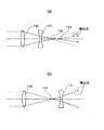
多くの場合、熱レンズを用いた光熱変換分光分析方法を用いる場合には、励起光の焦点位置と検出光の焦点位置とが異なっていることが必要となる。図3は、励起光の光軸方向(Z方向)に関する熱レンズの形成位置と検出光の焦点位置の説明図であり、(a)は対物レンズが色収差をもつ場合を示し、(b)は対物レンズが色収差を持たない場合を示す。 In many cases, when the photothermal conversion spectroscopic analysis method using a thermal lens is used, it is necessary that the focal position of the excitation light and the focal position of the detection light are different. FIG. 3 is an explanatory diagram of the thermal lens formation position and the focus position of the detection light in the optical axis direction (Z direction) of the excitation light, (a) shows the case where the objective lens has chromatic aberration, and (b) The case where an objective lens does not have chromatic aberration is shown.
対物レンズ130が色収差を持つ場合は、図3(a)に示すように、熱レンズ131は、励起光の焦点位置132に形成されると共に、検出光の焦点位置133はΔLだけ励起光の焦点位置132からずれるので、この検出光により熱レンズ131の屈折率の変化を検出光の焦点距離の変化として検出することができる。一方、対物レンズ130が色収差をもたない場合は、図3(b)に示すように、検出光の焦点位置133は、励起光の焦点位置132に形成される熱レンズ131の位置とほぼ一致する。この結果、検出光には熱レンズ131による偏向が生じないので、熱レンズ131の屈折率の変化は検出できない。
When the
しかしながら、顕微鏡の対物レンズは、通常、色収差をもたないように製造されている。したがって、上記の理由により、検出光の焦点位置133は、励起光の焦点位置132に形成される熱レンズ131の位置とほぼ一致し(図3(b))、熱レンズ131の屈折率の変化を検出することができない。このため、測定の度に、熱レンズ131が形成される試料の位置を、図4(a)および図4(b)に示すように、検出光の焦点位置133からずらしたり、図5に示すように、不図示のレンズを用いて検出光を若干発散または集光させて対物レンズに入射させることにより検出光の焦点位置133を熱レンズ131からずらしたりしなければならず、ユーザーの作業効率が悪いという問題がある。
However, an objective lens of a microscope is usually manufactured so as not to have chromatic aberration. Therefore, for the above reason, the
また、従来、光熱変換分光分析において、検出光を感度良く検出するための方法が知られていなかったため、測定感度の設計をすることができず、高性能なマイクロ化学システムを安定して製造することができないという問題があった。 Conventionally, in photothermal conversion spectroscopic analysis, since a method for detecting detection light with high sensitivity has not been known, measurement sensitivity cannot be designed, and a high-performance microchemical system can be stably manufactured. There was a problem that I could not.
本発明の目的は、高感度な分析および検出ができる光熱変換分光分析法、及び該方法を実行する小型のマイクロ化学システムを提供することにあり、さらには光熱変換分光分析法に適した流路深さを有した流路を使用することにより、より高感度な光熱変換分光分析法、及び該方法を用いたマイクロ化学システムを提供することにある。 An object of the present invention is to provide a photothermal conversion spectroscopic method capable of highly sensitive analysis and detection, and a small microchemical system for executing the method, and further, a flow path suitable for the photothermal conversion spectroscopic method. An object of the present invention is to provide a photothermal conversion spectroscopic method with higher sensitivity and a microchemical system using the method by using a channel having a depth.
上記目的を達成するために、請求項1に記載の発明は、マイクロ化学システムであって、試料を流すための流路と、波長の異なる2種の光を出射する光出射手段と、前記光出射手段からの出射光を集光して前記流路に向けて焦点を結ぶ集光レンズと、前記流路を透過した前記出射光の強度を検出する検出手段とを備えたマイクロ化学システムにおいて、前記流路の深さが、前記異なる2種の光が結ぶ焦点位置の距離の差の2倍以上であることを特徴とする。
In order to achieve the above object, the invention described in
請求項2に記載の発明は、請求項1に記載のマイクロ化学システムであって、前記集光レンズは、色収差を有していることを特徴とする。 A second aspect of the present invention is the microchemical system according to the first aspect, wherein the condenser lens has chromatic aberration.
請求項3に記載の発明は、請求項1または2に記載のマイクロ化学システムであって、前記集光レンズはロッドレンズであることを特徴とする。 A third aspect of the present invention is the microchemical system according to the first or second aspect, wherein the condenser lens is a rod lens.
請求項4に記載の発明は、請求項1乃至3のいずれか1項に記載のマイクロ化学システムであって、前記出射手段と前記集光レンズとが光ファイバーで結合されていることを特徴とする。 A fourth aspect of the present invention is the microchemical system according to any one of the first to third aspects, wherein the emitting means and the condenser lens are coupled by an optical fiber. .
請求項5に記載の発明は、請求項4に記載のマイクロ化学システムであって、前記光ファイバーは、シングルモードファイバーであることを特徴とする。 The invention according to claim 5 is the microchemical system according to claim 4, wherein the optical fiber is a single mode fiber.
請求項6に記載の発明は、光熱変換分光分析方法であって、分析対象となる流体に、励起光を集光照射することによって、前記流体中に熱レンズを生成し、前記熱レンズに検出光を集光照射し、前記熱レンズを透過した前記検出光の強度を測定する光熱変換分光分析方法において、前記励起光と前記検出光の焦点位置の距離の差が、前記流体の深さの半分以下となるようにすることを特徴とする。 The invention according to claim 6 is a photothermal conversion spectroscopic analysis method, in which a thermal lens is generated in the fluid by condensing and irradiating the fluid to be analyzed, and detected by the thermal lens. In the photothermal conversion spectroscopic analysis method of collecting and irradiating light and measuring the intensity of the detection light transmitted through the thermal lens, the difference in the distance between the focal positions of the excitation light and the detection light is the depth of the fluid. It is characterized by being less than half.
本発明によれば、検出対象試料を流す流路の深さが、励起光および検出光の焦点位置差の2倍以上であるので、十分な信号強度が得られ、高感度な検出が可能となるため、従来は測定することができなかった微小な反応についても測定することができる。 According to the present invention, the depth of the flow path through which the sample to be detected flows is at least twice the focal position difference between the excitation light and the detection light, so that sufficient signal intensity can be obtained and highly sensitive detection is possible. Therefore, it is possible to measure a minute reaction that could not be measured conventionally.
本発明によれば、集光レンズは色収差を有しているので、励起光及び検出光の焦点位置を調整するための光学系を省略でき、装置を小型化することができる。 According to the present invention, since the condensing lens has chromatic aberration, an optical system for adjusting the focal positions of the excitation light and the detection light can be omitted, and the apparatus can be miniaturized.
本発明によれば、集光レンズはロッドレンズであるので、集光レンズを小さくすることができ、流路に集光レンズを近づけることができるため、マイクロ化学システムをより小型化することができる。 According to the present invention, since the condensing lens is a rod lens, the condensing lens can be made small, and the condensing lens can be brought close to the flow path, so that the microchemical system can be further downsized. .
本発明によれば、励起光および検出光を集光レンズまで導くための導光路として、光ファイバーを用いているので、測定の度に励起光及び検出光の光路を調整する必要がなく、ユーザーの作業効率が向上する。また、光路を調整するための冶具が不要なのでマイクロ化学システムを小型化できる。1本の光ファイバーで励起光および検出光を伝搬する場合には、励起光と検出光は常に同軸となるため、光軸を調整する冶具が不要であり、マイクロ化学システムをさらに小型化できる。 According to the present invention, since the optical fiber is used as the light guide for guiding the excitation light and the detection light to the condenser lens, it is not necessary to adjust the optical path of the excitation light and the detection light every time measurement is performed. Work efficiency is improved. In addition, since a jig for adjusting the optical path is not required, the microchemical system can be miniaturized. When the excitation light and the detection light are propagated by a single optical fiber, the excitation light and the detection light are always coaxial, so that a jig for adjusting the optical axis is unnecessary, and the microchemical system can be further miniaturized.
本発明によれば、シングルモードの光ファイバーを用いるため、励起光によって生成される熱レンズが収差の少ない小さなレンズとなり、より正確な検出ができる。 According to the present invention, since a single mode optical fiber is used, the thermal lens generated by the excitation light becomes a small lens with little aberration, and more accurate detection can be performed.
以下、図面を参照しながら本発明の具体的な実施形態について説明する。 Hereinafter, specific embodiments of the present invention will be described with reference to the drawings.
本発明者らは鋭意研究の結果、マイクロ化学システムに適用する光熱変換分光分析方法において、検出光の強度は、励起光と検出光の焦点位置の差と流路の深さの関係に依存することを見出した。 As a result of intensive studies, the present inventors have determined that the intensity of the detection light depends on the relationship between the difference between the focal positions of the excitation light and the detection light and the depth of the flow path in the photothermal conversion spectroscopic analysis method applied to the microchemical system. I found out.
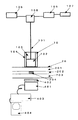
図1は、本発明の実施の形態に係るマイクロ化学システムの概略構成を示す概略図である。図1において、マイクロ化学システムはレンズを内蔵する光ファイバー10(以下レンズ付き光ファイバー10)を備えている。光ファイバー10は後端側(図面上では上側)に、励起光及び検出光をシングルモードで伝搬する光ファイバー101が挿入されており、この光ファイバー101の挿入端は屈折率分布型ロッドレンズ102の一端に接続されている。光ファイバー101の外径を屈折率分布型ロッドレンズ102の外径と同一にするために、屈折率分布型ロッドレンズ102の外径と同一の外径を有するフェルール103が光ファイバー101を囲むように設けられている。光ファイバー101はフェルール103によって固定されており、屈折率分布型ロッドレンズ102とフェルール103とはチューブ104内に固定されている。ここで、光ファイバー101と屈折率分布型ロッドレンズ102とは密着していてもよいし、隙間があっても良い。このレンズ付き光ファイバー10は、後述する流路付き板状部材20の表面で流路204に面する位置に固定されている。レンズ付き光ファイバー10は、接着剤を用いて流路付き板状部材20に直接に接着してもよいし、冶具を用いて固定してもよい。また、不図示の冶具を用いて流路つき板状部材20と離して固定してもよい。レンズ付き光ファイバー10を流路付き板状部材20に接着する接着剤には、紫外線硬化型、熱硬化型、2液硬化型等のアクリル系接着剤、エポキシ系接着剤等の有機系接着剤、および無機系接着剤等を用いることができる。なお、レンズ102は所定の色収差を有しているものであれば、屈折率分布型ロッドレンズに限られるものではない。
FIG. 1 is a schematic diagram showing a schematic configuration of a microchemical system according to an embodiment of the present invention. In FIG. 1, the microchemical system includes an
屈折率分布型ロッドレンズ102は、円柱状の透明なレンズであり、長手方向に延びる中心線位置から半径方向に屈折率が連続的に変化するものである。このようなロッドレンズは、中心線位置の屈折率をn0、2乗分布定数をgとして、中心線位置から半径方向にrの距離にある位置の屈折率n(r)が、近似的にrに関する2次方程式
n(r)=n0{1−(g2/2)・r2}
で表される集束性光伝送体として知られている。
The gradient
n (r) = n 0 { 1- (g 2/2) · r 2}
It is known as a convergent light transmitter represented by
屈折率分布型ロッドレンズ102は、その全長z0を0<z0<π/2gの範囲内で選択する場合、両端面が平坦でありながら通常の凸レンズと同じ結像性を有し、平行入射光線によって出射端より
s0=cot(gz0)/n0g
の位置に焦点が作られる。
When the total length z 0 is selected within the range of 0 <z 0 <π / 2g, the gradient
s 0 = cot (gz 0 ) / n 0 g
The focus is made at the position of.
屈折率分布型ロッドレンズ102の底面が平面であるので、光ファイバー端面に容易に取り付けられるとともに、屈折率分布型ロッドレンズ102の光軸と光ファイバー101の光軸とを容易に一致させることができる。また、屈折率分布型ロッドレンズ102は円柱状であるのでレンズ付き光ファイバー10も容易に円柱状にできる。
Since the bottom surface of the gradient
光ファイバー101をシングルモードとしたのは、光熱変換分光分析法を利用して試料中の微量な溶質を検出する場合、励起光をできるだけ小さく絞り、光熱変換に利用されるエネルギーを高くするととともに、励起光によって生成する熱レンズが収差の少ないレンズになることが望ましいからである。 The optical fiber 101 is set to the single mode because, when detecting a very small amount of solute in the sample using photothermal conversion spectroscopy, the excitation light is reduced as much as possible to increase the energy used for the photothermal conversion and the excitation. This is because it is desirable that the thermal lens generated by light is a lens with less aberration.
この点、シングルモードの光ファイバー101から出射される光は常にガウス分布になるので、励起光の焦点が小さくなる。また、励起光によって生成された熱レンズが小さい場合、この熱レンズを透過する検出光の光量をできる限り多くするためには、検出光もできる限り小さく絞ることが望ましい。この点からも、光ファイバーは励起光及び検出光をシングルモードで伝搬するものであることが好ましい。 In this respect, the light emitted from the single-mode optical fiber 101 always has a Gaussian distribution, so that the focal point of the excitation light becomes small. Further, when the thermal lens generated by the excitation light is small, it is desirable to reduce the detection light as small as possible in order to increase the amount of detection light transmitted through the thermal lens as much as possible. Also from this point, the optical fiber preferably propagates the excitation light and the detection light in a single mode.
なお、光ファイバー101は励起光及び検出光を透過させるものであればどのようなものでも使用はできるが、マルチモード光ファイバーを使用した場合は、出射光がガウス分布にならない上に、光ファイバー101の曲がり具合等の種々の条件によって出射パターンが変化するので、必ずしも安定な出射光が得られない。このため、微量な溶質の測定が困難になるとともに測定値が安定しない場合がある。したがって、上述のように光ファイバー101はシングルモードのものが好ましい。 The optical fiber 101 may be any optical fiber that transmits the excitation light and the detection light. However, when a multimode optical fiber is used, the emitted light does not have a Gaussian distribution and the optical fiber 101 is bent. Since the emission pattern changes depending on various conditions such as conditions, stable emission light cannot always be obtained. For this reason, measurement of a very small amount of solute becomes difficult and the measured value may not be stable. Therefore, as described above, the optical fiber 101 is preferably a single mode.
光ファイバーの先端を球形等に加工してレンズとすれば、光ファイバーの先端にレンズを取り付けなくても励起光および検出光を絞ることが可能であるが、この場合、色収差がほとんどないために励起光と検出光の焦点位置がほぼ同じとなる。このため、熱レンズの信号がほとんど検出されないという問題がある。また、光ファイバー先端の加工によるレンズは収差が大きいので、励起光および検出光の焦点が大きいという問題もある。したがって、本実施の形態では光ファイバー101の先端にレンズ102が取りつけられている。
If the tip of the optical fiber is processed into a sphere or the like to form a lens, the excitation light and the detection light can be reduced without attaching a lens to the tip of the optical fiber, but in this case there is almost no chromatic aberration, so the excitation light And the focus position of the detection light is substantially the same. For this reason, there is a problem that the signal of the thermal lens is hardly detected. Further, since the lens formed by processing the tip of the optical fiber has a large aberration, there is a problem that the focal points of the excitation light and the detection light are large. Therefore, in this embodiment, the
光ファイバー101の他方端には励起光用光源105、検出光用光源106、励起光用光源を変調するために用いる変調器107、光ファイバー内に入射された励起光と検出光とを合わせる2波長合波器108が配設されている。なお、2波長合波器108を用いる代わりに、ダイクロイックミラーを用いて励起光と検出光を合波してから光ファイバー101へ入射させてもよい。
The other end of the optical fiber 101 has an
検出するための試料を流す流路付き板状部材20は、例えば3層に重ねて接着されたガラス基板201、202、203から成る。ガラス基板202には混合、攪拌、合成、分離、抽出、検出等の際に試料を流す上記の流路204が形成されている。
The plate-
この流路付き板状部材20の材料は耐久性、耐薬品性の面からガラスが望ましく、さらに、細胞等の生体試料、例えばDNA解析用としての用途を考慮すると、耐酸性、耐アルカリ性の高いガラス、具体的には、硼珪酸ガラス、ソーダライムガラス、アルミノ硼珪酸ガラス、石英ガラス等が好ましい。しかし、用途を限定することによってプラスチック等の有機物を用いることができる。
The material of the plate-
ガラス基板201、202、203同士を接着させる接着剤には、例えば、紫外線硬化型、熱硬化型、2液硬化型のアクリル系、エポキシ系の有機接着剤、及び無機接着剤等がある。また、熱融着によってガラス基板201〜203同士を融着させてもよい。
Examples of the adhesive that bonds the
流路204に面する位置において、レンズ付き光ファイバー10に対向する位置には、検出光を検出するための光電変換器401、励起光と検出光とを分離して検出光のみを選択的に透過させる波長フィルター402が配設されている。検出光の一部のみを選択的に透過させるためのピンホールが形成された部材をそのピンホールが検出光の光路上でかつ光電変換器401よりも上流の位置に位置するように配置しても良い。
At the position facing the
光電変換器401より得られた信号は、励起光を変調するために用いられた変調器107と同期させるためにロックインアンプ404に送られ、その後コンピューター405で解析される。
The signal obtained from the
屈折率分布型ロッドレンズ102の励起光の焦点位置は、流路付き板状部材20の流路204の中に位置する事が望ましい。屈折率分布型ロッドレンズ102は流路付き板状部材20に接触している必要はないが、接触する場合は流路付き板状部材20の上部ガラス板201の厚みで屈折率分布型ロッドレンズ102の焦点距離を調整できる。上部ガラス板201の厚みが足りない場合は、屈折率分布型ロッドレンズ102と上部ガラス板201との間に焦点距離を調整するためのスペーサーを入れてもよい。
The focal position of the excitation light of the gradient
屈折率分布型ロッドレンズ102は、励起光の焦点位置に対して検出光の焦点位置がわずかにΔLだけずれるように設定される(図3(a))。
The gradient
Icは、共焦点長(nm)として、Ic=π・(d/2)2/λ1で計算される。ここで、dはd=1.22×λ1/NAで計算されるエアリーディスクであり、λ1は、励起光の波長(nm)であり、NAは、屈折率分布型ロッドレンズ102の開口数である。光ファイバーを用いる場合は、光ファイバーの出射光の開口数が小さいため、大きな開口数を有するロッドレンズを用いた場合の共焦点長の計算には光ファイバーの開口数を考慮する必要がある。
Ic is calculated as Ic = π · (d / 2) 2 / λ 1 as the confocal length (nm). Here, d is an Airy disk calculated by d = 1.22 × λ 1 / NA, λ 1 is the wavelength (nm) of excitation light, and NA is the aperture of the gradient
共焦点長より薄い試料を測定する場合は、上記ΔL値は、ΔL=√3・Icであることが最も好ましい。このΔLの値は、検出光の焦点位置と励起光の焦点位置の差を表しているので、検出光の焦点距離が励起光の焦点距離よりも長い場合であっても、短い場合であっても同じ結果となる。 When measuring a sample thinner than the confocal length, the ΔL value is most preferably ΔL = √3 · Ic. The value of ΔL represents the difference between the focal position of the detection light and the focal position of the excitation light. Therefore, even if the focal length of the detection light is longer than the focal distance of the excitation light, Gives the same result.
マイクロ化学システムに用いられる板状部材に作製する流路は、50〜100μmの深さとする。これは下記の理由によるためである。マイクロ化学システムでは、板状部材内に作製された微細な流路内で液中試料の混合、反応、分離、抽出、検出等を行うため、ビーカー等を用いた一般的な化学操作に比較して、用いる試料の量を少なくすることができる、反応を高速に行うことができる、装置を小型化することができる等の利点を有している。この中で、反応の高速化に関してより詳しく説明する。マイクロ化学システムを用いることで特にメリットが得られる反応としては、界面を介して反応が進行する液液界面反応がある。この反応においては、各溶液中に含まれる反応物が界面で接触することによって反応が進行する。反応は界面のみで起こるため、反応速度は各溶液中の反応物がいかに界面に到達するかで決定される。よって、比界面積(溶液の体積に対する界面の割合)が重要となる。マイクロ化学システムでは流路にそって界面を形成できるため、ビーカー等での反応に対して非常に大きな比界面積を取ることが可能となり、そのため、反応の高速化が可能となる。この比界面積をより大きくして反応を高速化するためには、界面からの溶液の深さ、すなわち溝の幅を小さくすることが重要となる。しかしながら、現在マイクロ化学システムで用いられている溝の作製方法のウエットエッチング等の方法では、作製できる溝のアスペクト比(溝幅と深さの比)が限られているため、溝幅のみを単独で制御することはできず、溝幅を狭くするためには溝の深さも浅くする必要がある。 The flow path produced in the plate-like member used for the microchemical system has a depth of 50 to 100 μm. This is because of the following reason. In microchemical systems, mixing, reaction, separation, extraction, detection, etc. of submerged samples are carried out in a fine flow path created in a plate-like member. Compared to general chemical operations using beakers, etc. Thus, there are advantages that the amount of the sample to be used can be reduced, the reaction can be performed at high speed, and the apparatus can be miniaturized. In this, the speeding up of the reaction will be described in more detail. As a reaction that can obtain a particular advantage by using a microchemical system, there is a liquid-liquid interface reaction in which the reaction proceeds through the interface. In this reaction, the reaction proceeds by contact of reactants contained in each solution at the interface. Since the reaction occurs only at the interface, the reaction rate is determined by how the reactants in each solution reach the interface. Therefore, the specific interface area (ratio of the interface with respect to the volume of the solution) is important. In the microchemical system, since an interface can be formed along the flow path, it is possible to take a very large specific interface area for the reaction in a beaker or the like, and therefore, the reaction can be speeded up. In order to increase the specific interface area and speed up the reaction, it is important to reduce the depth of the solution from the interface, that is, the width of the groove. However, since the aspect ratio (ratio of groove width to depth) of the groove that can be produced is limited in the method such as wet etching that is currently used in the microchemical system, only the groove width is used alone. In order to reduce the groove width, it is necessary to reduce the depth of the groove.
以上のことから、反応を高速化するためには溝の深さは浅いほどよいことがわかる。ただ、あまり溝を小さくしすぎると、溝中で液体の特性が維持されなくなる、溝内へ液体を挿入することが難しくなる等の問題がでてくるため、50〜100μm程度の深さを有する溝を用いることが多い。上記のような流路に検出対象物質を含む溶液が流れている状態で光熱変換分光分析法を実施することは、試料の厚みが励起光の共焦点長に対して非常に厚いことを意味する。例えば、波長658nmの励起光をNA(開口数)0.25の対物レンズで集光した場合の共焦点長は、12.3μmであるが、流路の厚みはその4倍以上あることとなる。このように検出対象物質が共焦点長に対して厚い場合は、前記の薄膜の場合と比較すると、熱レンズを形成する薄膜が厚み方向に数多く積層した状態と同じになり、最終的にはその積分値になるので、薄膜の場合よりも励起光と検出光との焦点位置のずれの最適値は大きなものとなる。 From the above, it can be seen that the shallower the groove, the better for speeding up the reaction. However, if the groove is made too small, the characteristics of the liquid will not be maintained in the groove, and it will be difficult to insert the liquid into the groove. Therefore, the depth is about 50 to 100 μm. Often grooves are used. When the photothermal conversion spectroscopic analysis is performed in a state where the solution containing the detection target substance is flowing in the flow path as described above, the thickness of the sample is very thick with respect to the confocal length of the excitation light. . For example, the confocal length when the excitation light having a wavelength of 658 nm is condensed by an objective lens having an NA (numerical aperture) of 0.25 is 12.3 μm, but the thickness of the flow path is more than four times that. . In this way, when the detection target substance is thick with respect to the confocal length, compared to the case of the thin film described above, it becomes the same as a state in which a large number of thin films forming the thermal lens are stacked in the thickness direction. Since the integration value is obtained, the optimum value of the shift of the focal position between the excitation light and the detection light is larger than that in the case of the thin film.
このような焦点位置のずれを大きくした集光レンズを用いた場合は、励起光の焦点位置と検出光の焦点位置とが離れるため、励起光によって形成される熱レンズの深さ方向成分の影響をより受けることとなる。このため、光熱変換分光分析測定においては、用いる溝の深さは深いほど得られる信号強度が強くなるので望ましい。しかしながら、上述した反応速度と溝の深さとの関係では溝深さは浅いほど望ましいため、両者を考慮すると、溝の深さは色収差すなわち励起光と検出光の焦点位置差は2倍以上であることが望ましく、より望ましくは3倍以上である。 When a condensing lens with such a large focal position deviation is used, the focal position of the excitation light and the focal position of the detection light are separated from each other, so the influence of the depth direction component of the thermal lens formed by the excitation light. Will receive more. For this reason, in photothermal conversion spectroscopic analysis measurement, the deeper the groove used, the stronger the signal intensity obtained, which is desirable. However, since the shallower groove depth is desirable in the relationship between the reaction speed and the groove depth described above, considering both, the groove depth is chromatic aberration, that is, the focal position difference between the excitation light and the detection light is twice or more. It is desirable that the ratio is three times or more.
上記は、ウェットエッチングによって等方的な溝を作製する場合について述べたが、ウェットエッチング以外の方法(例えば機械的な研削、マスキングを利用した異方的なエッチング、ドライエッチングなど)で異方的な溝を作製するときは、チップ表面と垂直な面における溝の断面積が10〜1.0×105μm2の範囲となるように、溝の幅と深さを設計すればよい。前記面積の範囲内であれば、マイクロ化学チップとしての機能を発揮する反応速度や特性を得ることができる。 The above describes the case of forming an isotropic groove by wet etching, but is anisotropic by methods other than wet etching (for example, mechanical grinding, anisotropic etching using masking, dry etching, etc.). When producing a groove, the width and depth of the groove may be designed so that the cross-sectional area of the groove in a plane perpendicular to the chip surface is in the range of 10 to 1.0 × 10 5 μm 2 . If it is in the range of the said area, the reaction rate and characteristic which exhibit the function as a microchemical chip can be acquired.
光熱変換分光分析測定において、検出光の強度が、励起光および検出光の焦点位置の差と流路の深さに依存することを本発明者らは見出したが、光熱変換分光分析測定をマイクロ化学システムに適用するためには、上述したように、反応速度などとの関係で適切な溝深さが決定される。即ち、励起光および検出光の波長、溝深さ、必要とする検出強度の3つを考量してマイクロ化学システムの設計を行う必要がある。マイクロ化学システムに使用される波長は400〜1000nmが好ましく、反応速度の観点から溝深さは50〜100μmが好ましい。これらの条件から、十分な検出強度が得られ、かつ、十分な反応速度を得るためには、溝の深さは、励起光および検出光の焦点位置の差の約2〜4倍とすることが最も好ましい。 In the photothermal conversion spectroscopic measurement, the present inventors have found that the intensity of the detection light depends on the difference between the focal positions of the excitation light and the detection light and the depth of the flow path. For application to a chemical system, as described above, an appropriate groove depth is determined in relation to the reaction rate and the like. That is, it is necessary to design a microchemical system by taking into consideration three factors: the wavelength of excitation light and detection light, the groove depth, and the required detection intensity. The wavelength used in the microchemical system is preferably 400 to 1000 nm, and the groove depth is preferably 50 to 100 μm from the viewpoint of reaction rate. From these conditions, in order to obtain sufficient detection intensity and sufficient reaction speed, the groove depth should be about 2 to 4 times the difference between the focal positions of excitation light and detection light. Is most preferred.
屈折率分布型のロッドレンズを使用してどの程度の色収差が得られるかを例示する。用いる屈折率分布型ロッドレンズには、例えば日本板硝子株式会社のSELFOCTMレンズカタログに記載されているSLWを用いることができる。 An example of how much chromatic aberration can be obtained using a gradient index rod lens will be described. As the gradient index rod lens to be used, for example, SLW described in the SELFOC ™ lens catalog of Nippon Sheet Glass Co., Ltd. can be used.
流路付き板状部材の材質がパイレックス(登録商標)ガラス、流路上の厚み(上部ガラス201の厚み)が0.9mm、流路の深さ0.1mm。屈折率分布型ロッドレンズSLWの直径1mm、ロッド長2.3mm、励起光波長658nm、検出光波長785nm、励起光の焦点位置が流路の真ん中とした場合に得られる焦点位置差(ΔL)は37μmである。 The material of the plate member with flow path is Pyrex (registered trademark) glass, the thickness on the flow path (the thickness of the upper glass 201) is 0.9 mm, and the depth of the flow path is 0.1 mm. The focal position difference (ΔL) obtained when the diameter of the gradient index rod lens SLW is 1 mm, the rod length is 2.3 mm, the excitation light wavelength is 658 nm, the detection light wavelength is 785 nm, and the focal position of the excitation light is in the middle of the flow path. 37 μm.
このレンズを集光レンズとして用い、板状部材に作製された流路深さと熱レンズ信号強度にどのような関係があるかを測定した結果を図6に示す。これは下記条件において測定した場合のものである。 FIG. 6 shows the result of measuring the relationship between the depth of the flow path formed in the plate-like member and the thermal lens signal intensity using this lens as a condenser lens. This is when measured under the following conditions.
測定試料としては、ニッケルフタロシアニンスルホン酸四ナトリウム塩を10-5モル/リットルの濃度で溶解した水溶液を、各深さを有する板状部材に作製された流路に入れ、液を止めた状態で測定した。励起光の波長は658nm、検出光の波長は785nm、励起光の変調速度は1kHzであり、励起光の焦点位置を溝の中央に固定して測定した。 As a measurement sample, an aqueous solution in which nickel phthalocyanine sulfonic acid tetrasodium salt was dissolved at a concentration of 10 −5 mol / liter was put in a flow path formed in a plate member having each depth, and the liquid was stopped. It was measured. The wavelength of the excitation light was 658 nm, the wavelength of the detection light was 785 nm, the modulation speed of the excitation light was 1 kHz, and the measurement was performed with the focal position of the excitation light fixed at the center of the groove.
図6において、信号強度が最大になるのは板状部材に作製された流路の深さが160μm以上であり、これは用いた集光レンズの色収差の約4.3倍に相当する。信号強度が最大の9割となるのは板状部材に作製された流路が120μm(集光レンズの色収差の3.2倍)であり、信号強度が最大の6割となるのは75μm(集光レンズの色収差の2倍)であった。 In FIG. 6, the signal intensity is maximized when the depth of the flow path formed in the plate member is 160 μm or more, which corresponds to about 4.3 times the chromatic aberration of the condenser lens used. The signal intensity is 90% at the maximum, the flow path made in the plate member is 120 μm (3.2 times the chromatic aberration of the condensing lens), and the signal intensity is 60 μm at the maximum is 75 μm ( 2 times the chromatic aberration of the condensing lens).
上述の屈折率分布型ロッドレンズSLWは、他の屈折率分布型ロッドレンズと組み合わせることによって色収差を調整することができる。SLWレンズと日本板硝子株式会社のSELFOCTMレンズカタログに記載されているSLA12相当レンズと組み合わせることによって色収差20μmの集光レンズを作製し、板状部材に作製された流路深さと熱レンズ信号強度にどのような関係があるかを測定した結果を図7に示す。 The above-described gradient index rod lens SLW can adjust chromatic aberration by combining with other gradient index rod lenses. A condensing lens with a chromatic aberration of 20 μm is produced by combining an SLW lens with an SLA12 equivalent lens described in the SELFOC TM lens catalog of Nippon Sheet Glass Co., Ltd. FIG. 7 shows the result of measuring what kind of relationship there is.
図7において、信号強度が最大になるのは板状部材に作製された流路の深さが100μm以上であり、これは用いた集光レンズの色収差の約5倍に相当する。信号強度が最大の9割となるのは板状部材に作製された流路が70μm(集光レンズの色収差の3.5倍)であり、信号強度が最大の5割となるのは40μm(集光レンズの色収差の2倍)であった。 In FIG. 7, the signal intensity is maximized when the depth of the flow path formed in the plate member is 100 μm or more, which corresponds to about 5 times the chromatic aberration of the condenser lens used. The signal intensity is 90% at the maximum is 70 μm for the flow path formed in the plate member (3.5 times the chromatic aberration of the condensing lens), and the signal intensity is 50 μm at the maximum 50%. 2 times the chromatic aberration of the condensing lens).
以上のように、マイクロ化学システムに用いる流路の深さは反応の高速化を考えると浅い程よいが、あまり浅くしすぎてしまうと得られる熱レンズ信号の強度が小さくなり、検出感度が低下してしまうという問題がある。そのため、溝の深さを集光レンズの色収差すなわち励起光と検出光の焦点位置差の2倍以上にすることにより、熱レンズ信号の強度を最高値の5割以上とすることができるので、反応速度を大きく保ったまま、測定するための十分な検出強度を得ることが可能となる。また、反応速度が大きい反応を測定するときや、反応速度が小さくても良い測定の場合、マイクロ化学システムに用いる流路の深さを集光レンズの励起光と検出光の焦点位置差の3倍以上にしてもよい。若干反応速度はやや小さくなるが、熱レンズ信号の強度を最高値の7割以上とすることができるので、検出感度をより向上させることが可能となる。 As described above, the depth of the flow path used in the microchemical system should be as shallow as possible in view of the speeding up of the reaction. However, if the depth is too shallow, the intensity of the thermal lens signal obtained decreases, and the detection sensitivity decreases. There is a problem that it ends up. Therefore, the intensity of the thermal lens signal can be increased to 50% or more of the maximum value by making the depth of the groove more than twice the chromatic aberration of the condenser lens, that is, the focal position difference between the excitation light and the detection light. It is possible to obtain a sufficient detection intensity for measurement while keeping the reaction rate large. Also, when measuring a reaction with a high reaction rate or when the reaction rate may be low, the depth of the flow path used in the microchemical system is 3 of the focal position difference between the excitation light of the condenser lens and the detection light. It may be doubled or more. Although the reaction speed is slightly reduced, the intensity of the thermal lens signal can be increased to 70% or more of the maximum value, so that the detection sensitivity can be further improved.
本発明の実施の形態によれば、集光レンズとして用いた屈折率分布型ロッドレンズの色収差に適した深さを有した流路を備える板状部材を用いているため、高感度の測定ができる。また、励起光または検出光の焦点位置を調整するための光学系を別途設置する必要がなくなるために装置を小型化することができる。 According to the embodiment of the present invention, since a plate-like member having a flow path having a depth suitable for the chromatic aberration of the gradient index rod lens used as a condenser lens is used, high-sensitivity measurement is possible. it can. Further, it is not necessary to separately install an optical system for adjusting the focal position of the excitation light or detection light, so that the apparatus can be miniaturized.
本発明は、微細な流路中を流れる微量試料の反応を検出することができるマイクロ化学システムおよび該マイクロ化学システムに適用できる光熱変換分光分析方法に利用することができる。 INDUSTRIAL APPLICABILITY The present invention can be used for a microchemical system that can detect a reaction of a small amount of sample flowing in a fine channel and a photothermal conversion spectroscopic analysis method that can be applied to the microchemical system.
10 先端にレンズを取り付けた光ファイバー
20 流路付き板状部材
101 光ファイバー
102 屈折率分布型ロッドレンズ
103 フェルール
104 チューブ
105 励起光用光源
106 検出光用光源
107 励起光変調器
108 2波長合波器
130 対物レンズ
131 熱レンズ
132 励起光の焦点位置
133 検出光の焦点位置
134 熱レンズによってずれた検出光の焦点位置
201、202、203 ガラス基板
204 混合、攪拌、合成、分離、抽出、検出用溝
401 光電変換器
402 波長フィルター
403 ロックインアンプ
404 コンピューター
10 Optical fiber with a lens attached to the tip
20 Plate member with flow path
101 optical fiber
102 gradient index rod lens
103 Ferrule
104 tubes
105 Light source for excitation light
106 Light source for detection light
107 Excitation light modulator
108 Two-wavelength multiplexer
130 Objective lens
131 thermal lens
132 Focal position of excitation light
133 Focus position of detection light
134 Focal position of detection light shifted by thermal lens
201, 202, 203 Glass substrate
204 Mixing, stirring, synthesis, separation, extraction, detection groove
401 photoelectric converter
402 Wavelength filter
403 Lock-in amplifier
404 computer
Claims (6)
Priority Applications (3)
| Application Number | Priority Date | Filing Date | Title |
|---|---|---|---|
| JP2004150828A JP2005331407A (en) | 2004-05-20 | 2004-05-20 | Photothermal conversion spectral analyzing method and microchemical system for performing the same |
| US11/132,892 US20050259259A1 (en) | 2004-05-20 | 2005-05-18 | Photothermal conversion spectroscopic analysis method and microchemical system for implementing the method |
| CN200510072857.5A CN1699972A (en) | 2004-05-20 | 2005-05-20 | Photothermal conversion spectroscopic analysis method and microchemical system for implementing the method |
Applications Claiming Priority (1)
| Application Number | Priority Date | Filing Date | Title |
|---|---|---|---|
| JP2004150828A JP2005331407A (en) | 2004-05-20 | 2004-05-20 | Photothermal conversion spectral analyzing method and microchemical system for performing the same |
Publications (2)
| Publication Number | Publication Date |
|---|---|
| JP2005331407A true JP2005331407A (en) | 2005-12-02 |
| JP2005331407A5 JP2005331407A5 (en) | 2007-02-22 |
Family
ID=35374843
Family Applications (1)
| Application Number | Title | Priority Date | Filing Date |
|---|---|---|---|
| JP2004150828A Pending JP2005331407A (en) | 2004-05-20 | 2004-05-20 | Photothermal conversion spectral analyzing method and microchemical system for performing the same |
Country Status (3)
| Country | Link |
|---|---|
| US (1) | US20050259259A1 (en) |
| JP (1) | JP2005331407A (en) |
| CN (1) | CN1699972A (en) |
Families Citing this family (3)
| Publication number | Priority date | Publication date | Assignee | Title |
|---|---|---|---|---|
| JP3824224B2 (en) * | 2002-09-27 | 2006-09-20 | 日本板硝子株式会社 | Micro chemical system |
| JP5297887B2 (en) * | 2009-05-19 | 2013-09-25 | 日本板硝子株式会社 | Optical demultiplexing detector and fluorescence detection system for fluorescence analysis |
| CN105510234A (en) * | 2015-12-31 | 2016-04-20 | 合肥知常光电科技有限公司 | Optical fiber sensing-based laser excitation heat wave signal detection device |
Family Cites Families (6)
| Publication number | Priority date | Publication date | Assignee | Title |
|---|---|---|---|---|
| DE69132273D1 (en) * | 1990-10-10 | 2000-08-03 | Univ Maryland | METHOD AND DEVICE FOR DETERMINING THE LIFETIME OF FLUORESCENCE IN FLOW CYTOMETRY |
| US5121405A (en) * | 1990-12-20 | 1992-06-09 | Coherent, Inc. | Alignment control system for lasers |
| JP2003021704A (en) * | 2001-07-10 | 2003-01-24 | Nippon Sheet Glass Co Ltd | A pair of refractive index distributed rod lenses and microchemical system equipped with the lenses |
| JP2003042982A (en) * | 2001-07-27 | 2003-02-13 | Nippon Sheet Glass Co Ltd | Photothermal conversion spectroscopic analysis method and microchemical system for conducting the method |
| US6760356B2 (en) * | 2002-04-08 | 2004-07-06 | The Regents Of The University Of California | Application of Yb:YAG short pulse laser system |
| JP2003344323A (en) * | 2002-05-30 | 2003-12-03 | Nippon Sheet Glass Co Ltd | Photothermal conversion spectroscopic analysis method and photothermal conversion spectroscopic analyzer implementing the method |
-
2004
- 2004-05-20 JP JP2004150828A patent/JP2005331407A/en active Pending
-
2005
- 2005-05-18 US US11/132,892 patent/US20050259259A1/en not_active Abandoned
- 2005-05-20 CN CN200510072857.5A patent/CN1699972A/en active Pending
Also Published As
| Publication number | Publication date |
|---|---|
| CN1699972A (en) | 2005-11-23 |
| US20050259259A1 (en) | 2005-11-24 |
Similar Documents
| Publication | Publication Date | Title |
|---|---|---|
| US6941041B2 (en) | Gradient index rod lens unit and microchemical system having the same | |
| US6930778B2 (en) | Microchemical system | |
| JP3969699B2 (en) | Chip member for microchemical system, and microchemical system using the chip member | |
| JP3824224B2 (en) | Micro chemical system | |
| TW200424516A (en) | Chip element for microchemical systems , and microchemical system using the chip element | |
| JP3848125B2 (en) | Photothermal conversion spectroscopic analysis method and microchemical system | |
| US7012692B2 (en) | Photothermal conversion spectroscopic analysis method, and photothermal conversion spectroscopic analysis apparatus for carrying out the method | |
| US20050259259A1 (en) | Photothermal conversion spectroscopic analysis method and microchemical system for implementing the method | |
| US7057729B2 (en) | Photothermal conversion spectroscopic analysis method, and photothermal conversion spectroscopic analysis apparatus for carrying out the method | |
| JP2004020262A (en) | Photothermal conversion spectroscopic method and apparatus therefor | |
| US20040071597A1 (en) | Chip member for micro chemical system, and micro chemical system using the chip member | |
| EP1416267A1 (en) | Micro chemical system, and method for light−heat conversion and spectral analysis performed by the system | |
| JP2004309270A (en) | Microchemical system | |
| JP2003194751A (en) | Micro chemical system | |
| JP2003270179A (en) | Microchemical system | |
| JP2002365251A (en) | Microchemical system | |
| JP2003130825A (en) | Method for photothermal spectroscopic analysis, and micro-chemical system |
Legal Events
| Date | Code | Title | Description |
|---|---|---|---|
| RD03 | Notification of appointment of power of attorney |
Free format text: JAPANESE INTERMEDIATE CODE: A7423 Effective date: 20060427 |
|
| A521 | Request for written amendment filed |
Free format text: JAPANESE INTERMEDIATE CODE: A523 Effective date: 20061222 |
|
| A621 | Written request for application examination |
Free format text: JAPANESE INTERMEDIATE CODE: A621 Effective date: 20070330 |
|
| A977 | Report on retrieval |
Free format text: JAPANESE INTERMEDIATE CODE: A971007 Effective date: 20080529 |
|
| A131 | Notification of reasons for refusal |
Free format text: JAPANESE INTERMEDIATE CODE: A131 Effective date: 20080610 |
|
| A02 | Decision of refusal |
Free format text: JAPANESE INTERMEDIATE CODE: A02 Effective date: 20081014 |