CN1699972A - Photothermal conversion spectroscopic analysis method and microchemical system for implementing the method - Google Patents
Photothermal conversion spectroscopic analysis method and microchemical system for implementing the method Download PDFInfo
- Publication number
- CN1699972A CN1699972A CN200510072857.5A CN200510072857A CN1699972A CN 1699972 A CN1699972 A CN 1699972A CN 200510072857 A CN200510072857 A CN 200510072857A CN 1699972 A CN1699972 A CN 1699972A
- Authority
- CN
- China
- Prior art keywords
- light
- lens
- passage
- thermal
- optical fiber
- Prior art date
- Legal status (The legal status is an assumption and is not a legal conclusion. Google has not performed a legal analysis and makes no representation as to the accuracy of the status listed.)
- Pending
Links
- 238000006243 chemical reaction Methods 0.000 title abstract description 38
- 238000000034 method Methods 0.000 title abstract description 21
- 238000004611 spectroscopical analysis Methods 0.000 title abstract description 6
- 238000001514 detection method Methods 0.000 claims abstract description 38
- 238000004458 analytical method Methods 0.000 claims abstract description 27
- 238000005259 measurement Methods 0.000 claims abstract description 11
- 239000013307 optical fiber Substances 0.000 claims description 44
- 230000004075 alteration Effects 0.000 claims description 30
- 238000001831 conversion spectrum Methods 0.000 claims description 19
- 230000003287 optical effect Effects 0.000 claims description 14
- 239000000835 fiber Substances 0.000 claims description 6
- 239000012530 fluid Substances 0.000 claims description 6
- 230000035945 sensitivity Effects 0.000 abstract description 7
- 239000000523 sample Substances 0.000 description 34
- 239000011521 glass Substances 0.000 description 14
- 230000005284 excitation Effects 0.000 description 11
- 239000012488 sample solution Substances 0.000 description 9
- 230000015572 biosynthetic process Effects 0.000 description 7
- 230000000694 effects Effects 0.000 description 7
- 239000000463 material Substances 0.000 description 7
- 239000000758 substrate Substances 0.000 description 7
- 239000011230 binding agent Substances 0.000 description 6
- 238000000926 separation method Methods 0.000 description 6
- 239000000243 solution Substances 0.000 description 6
- 239000007788 liquid Substances 0.000 description 5
- 230000008901 benefit Effects 0.000 description 4
- 238000009826 distribution Methods 0.000 description 4
- 238000000605 extraction Methods 0.000 description 4
- 238000010183 spectrum analysis Methods 0.000 description 4
- 239000003795 chemical substances by application Substances 0.000 description 3
- 238000005516 engineering process Methods 0.000 description 3
- 238000001039 wet etching Methods 0.000 description 3
- NIXOWILDQLNWCW-UHFFFAOYSA-N Acrylic acid Chemical compound OC(=O)C=C NIXOWILDQLNWCW-UHFFFAOYSA-N 0.000 description 2
- PXHVJJICTQNCMI-UHFFFAOYSA-N Nickel Chemical compound [Ni] PXHVJJICTQNCMI-UHFFFAOYSA-N 0.000 description 2
- 238000013459 approach Methods 0.000 description 2
- 239000007864 aqueous solution Substances 0.000 description 2
- 239000005388 borosilicate glass Substances 0.000 description 2
- 230000008859 change Effects 0.000 description 2
- 238000013461 design Methods 0.000 description 2
- 238000010586 diagram Methods 0.000 description 2
- 230000009977 dual effect Effects 0.000 description 2
- 229920006332 epoxy adhesive Polymers 0.000 description 2
- 230000003760 hair shine Effects 0.000 description 2
- 238000003780 insertion Methods 0.000 description 2
- 230000037431 insertion Effects 0.000 description 2
- 238000002156 mixing Methods 0.000 description 2
- 239000000376 reactant Substances 0.000 description 2
- 238000012360 testing method Methods 0.000 description 2
- 229920001187 thermosetting polymer Polymers 0.000 description 2
- 230000007704 transition Effects 0.000 description 2
- RZVAJINKPMORJF-UHFFFAOYSA-N Acetaminophen Chemical group CC(=O)NC1=CC=C(O)C=C1 RZVAJINKPMORJF-UHFFFAOYSA-N 0.000 description 1
- LSNNMFCWUKXFEE-UHFFFAOYSA-M Bisulfite Chemical compound OS([O-])=O LSNNMFCWUKXFEE-UHFFFAOYSA-M 0.000 description 1
- DGAQECJNVWCQMB-PUAWFVPOSA-M Ilexoside XXIX Chemical compound C[C@@H]1CC[C@@]2(CC[C@@]3(C(=CC[C@H]4[C@]3(CC[C@@H]5[C@@]4(CC[C@@H](C5(C)C)OS(=O)(=O)[O-])C)C)[C@@H]2[C@]1(C)O)C)C(=O)O[C@H]6[C@@H]([C@H]([C@@H]([C@H](O6)CO)O)O)O.[Na+] DGAQECJNVWCQMB-PUAWFVPOSA-M 0.000 description 1
- VYPSYNLAJGMNEJ-UHFFFAOYSA-N Silicium dioxide Chemical compound O=[Si]=O VYPSYNLAJGMNEJ-UHFFFAOYSA-N 0.000 description 1
- PNEYBMLMFCGWSK-UHFFFAOYSA-N aluminium oxide Inorganic materials [O-2].[O-2].[O-2].[Al+3].[Al+3] PNEYBMLMFCGWSK-UHFFFAOYSA-N 0.000 description 1
- WDEQGLDWZMIMJM-UHFFFAOYSA-N benzyl 4-hydroxy-2-(hydroxymethyl)pyrrolidine-1-carboxylate Chemical compound OCC1CC(O)CN1C(=O)OCC1=CC=CC=C1 WDEQGLDWZMIMJM-UHFFFAOYSA-N 0.000 description 1
- 230000005540 biological transmission Effects 0.000 description 1
- 238000007796 conventional method Methods 0.000 description 1
- 230000007812 deficiency Effects 0.000 description 1
- 230000002950 deficient Effects 0.000 description 1
- KPHWPUGNDIVLNH-UHFFFAOYSA-M diclofenac sodium Chemical compound [Na+].[O-]C(=O)CC1=CC=CC=C1NC1=C(Cl)C=CC=C1Cl KPHWPUGNDIVLNH-UHFFFAOYSA-M 0.000 description 1
- 238000009792 diffusion process Methods 0.000 description 1
- 230000003292 diminished effect Effects 0.000 description 1
- 238000001312 dry etching Methods 0.000 description 1
- 238000010894 electron beam technology Methods 0.000 description 1
- 238000005530 etching Methods 0.000 description 1
- 238000005286 illumination Methods 0.000 description 1
- 238000003384 imaging method Methods 0.000 description 1
- 238000009434 installation Methods 0.000 description 1
- 238000004519 manufacturing process Methods 0.000 description 1
- 239000000203 mixture Substances 0.000 description 1
- 229910052759 nickel Inorganic materials 0.000 description 1
- 238000006396 nitration reaction Methods 0.000 description 1
- 102000039446 nucleic acids Human genes 0.000 description 1
- 108020004707 nucleic acids Proteins 0.000 description 1
- 150000007523 nucleic acids Chemical class 0.000 description 1
- 239000011368 organic material Substances 0.000 description 1
- 239000002245 particle Substances 0.000 description 1
- -1 particularly Substances 0.000 description 1
- 239000004033 plastic Substances 0.000 description 1
- 229920003023 plastic Polymers 0.000 description 1
- 230000008569 process Effects 0.000 description 1
- 238000012545 processing Methods 0.000 description 1
- 102000004169 proteins and genes Human genes 0.000 description 1
- 108090000623 proteins and genes Proteins 0.000 description 1
- 239000005297 pyrex Substances 0.000 description 1
- 230000009467 reduction Effects 0.000 description 1
- 238000011160 research Methods 0.000 description 1
- 230000000630 rising effect Effects 0.000 description 1
- 239000004065 semiconductor Substances 0.000 description 1
- 239000005361 soda-lime glass Substances 0.000 description 1
- 229910052708 sodium Inorganic materials 0.000 description 1
- 239000011734 sodium Substances 0.000 description 1
- 239000002904 solvent Substances 0.000 description 1
- 238000000638 solvent extraction Methods 0.000 description 1
- 238000003756 stirring Methods 0.000 description 1
- 239000000126 substance Substances 0.000 description 1
- BDHFUVZGWQCTTF-UHFFFAOYSA-M sulfonate Chemical compound [O-]S(=O)=O BDHFUVZGWQCTTF-UHFFFAOYSA-M 0.000 description 1
- 230000001360 synchronised effect Effects 0.000 description 1
- 238000011144 upstream manufacturing Methods 0.000 description 1
Images


Classifications
-
- G—PHYSICS
- G01—MEASURING; TESTING
- G01N—INVESTIGATING OR ANALYSING MATERIALS BY DETERMINING THEIR CHEMICAL OR PHYSICAL PROPERTIES
- G01N21/00—Investigating or analysing materials by the use of optical means, i.e. using sub-millimetre waves, infrared, visible or ultraviolet light
- G01N21/17—Systems in which incident light is modified in accordance with the properties of the material investigated
- G01N21/171—Systems in which incident light is modified in accordance with the properties of the material investigated with calorimetric detection, e.g. with thermal lens detection
- G01N2021/1712—Thermal lens, mirage effect
Landscapes
- Physics & Mathematics (AREA)
- Health & Medical Sciences (AREA)
- Life Sciences & Earth Sciences (AREA)
- Chemical & Material Sciences (AREA)
- Analytical Chemistry (AREA)
- Biochemistry (AREA)
- General Health & Medical Sciences (AREA)
- General Physics & Mathematics (AREA)
- Immunology (AREA)
- Pathology (AREA)
- Investigating Or Analyzing Materials Using Thermal Means (AREA)
- Investigating Or Analysing Materials By Optical Means (AREA)
Abstract
A photothermal conversion spectroscopic analysis method which is capable of performing analysis, measurement and detection with high sensitivity. A sample flows in a channel. A exciting light and a detecting light are exited. A gradient refractive index rod lens converges the exited light and forms a focal point at a position in or close to the channel. Intensity of the exited light and passing through the channel are detected. A depth of the channel is not less than two time as large as a difference in distance between focal positions of the exciting light and the detecting light.
Description
Technical field
The microchemistry system that the present invention relates to a kind of photo-thermal conversion spectrum analysis method and be used to realize this method, it assembles ground with exciting light with detect illumination and be mapped on the sample in the solution, so that in this sample, form thermal lens, and measure the detection light that passes this thermal lens by exciting light; And the microchemistry system that the invention particularly relates to a kind of photo-thermal conversion spectrum analysis method and be used to realize this method, it can carry out high-precision ultramicro-analysis and can measure easily in selected arbitrarily position in very little space.
Background technology
Recently, the spectrum analysis method has been widely used as the method for analyzing or detecting semiconductor, biological specimen and various liquid samples.Yet, when in very little space, analyzing very small amount of material or very little material by conventional spectrum analysis method, existing needs the problem of vacuum as a measuring condition, and by using the electron beam or the particle beams can damage or destroy the problem of sample.
When the minute quantity sample in the Treatment Solution or in the biological tissue, needing basically to use can be with the optical microscope of high spatial resolution and high accuracy analysis sample.In fact be limited to the laser fluorescence microscope as this optical microscope.Therefore, naturally be: the object that analyze is limited to laser fluorescence microscope fluorescence molecule.
And at present, from chemical reaction velocity, use viewpoints such as very a small amount of sample reacts, on-the site analysis, the integrated technology that is used for carrying out in very little space chemical reaction has caused concern, and the whole world is studied this energetically.
So-called microchemistry system is an example of this integrated technology.In the microchemistry system, mixing in the very fine pipeline in being formed at little glass film plates or the like, reaction, separation, extraction or test sample solution.The example of the reaction of carrying out in this microchemistry system comprises diazo-reaction, nitration reaction and antigen-antibody reaction.And the example of extraction/separation comprises that solvent extraction, electrophoretic separation and row separate.The microchemistry system can be used to realize simple function, for example only is used for separating, and perhaps can be used to realize multiple function in the mode of combination.
As the example of the microchemistry system of the separation function that only is used for realizing above-mentioned functions, proposed to be used to analyze the electrophoretic apparatus (referring to, for example Japanese publication communique (Kokai) No.H8-178897) of indivisible protein, nucleic acid etc.This electrophoretic apparatus has the channel form plate-shaped member that is made of two glass film plates that link together.Because these parts are tabular, so compare, more be difficult for being damaged, and therefore processing is easier with the situation of glass capillary with circle or rectangular cross section.
In this microchemistry system, use is changed the spectrum analysis method by the photo-thermal of the thermal lensing effect that the photo-thermal conversion phenomena causes, caused concern as a kind of analytical approach with following characteristics: this method can be with high precision and high spatial resolution analyzing samples, need not to use vacuum field simultaneously, this method is so that the mode analyzing samples that sample does not contact with any parts of this system, therefore can not damage sample, this method can also analysis of fluorescence molecule sample in addition.
This photo-thermal conversion spectrum analysis method has been used the photo-thermal transition effects, when optical convergence when shining on the sample solution, light is absorbed by the solute in the sample solution, thereby release heat, therefore this heat makes the temperature part of solvent raise, therefore the refraction index changing of sample solution has formed thermal lens thus.
Fig. 2 is the view that is used to illustrate the thermal lens principle.
In Fig. 2, exciting light shines on the indivisible sample solution via object lens with assembling, and the photo-thermal transition effects has taken place thus.For most of materials, refractive index raises along with temperature and descends, therefore in exciting light has shone sample solution on it with having assembled, refractive index descends, and near the center of converging light, it is big more to descend more, and this center is the maximum place of temperature rising, and,, thermal diffusion diminishes because making temperature raise along with center away from converging light.On optical effect, final index distribution has produced the effect identical with concavees lens, so this effect is called thermal lensing effect.The size of thermal lensing effect, promptly the absorptivity of the focal power of concavees lens and sample solution is proportional.And, if refractive index along with temperature increases, has then formed convex lens.
In above-mentioned photo-thermal conversion spectrum analysis method, observed variation of temperature thus, i.e. change of refractive, so this method is suitable for detecting the concentration of minimum sample.
The example of the photo-thermal conversion spectroscopy apparatus of realizing above-mentioned photo-thermal conversion spectrum analysis method is disclosed in Japanese publication communique (Kokai) No.H10-232210.In traditional photo-thermal conversion spectroscopy apparatus, below microscopical object lens, place sample, and will introduce microscope from the exciting light of the predetermined wavelength of excitation source output.Therefore this exciting light shines on the zone of indivisible sample via microscopical object lens with assembling.The mode of assembling the position of ground irradiation at exciting light according to the center has formed thermal lens thus.
On the other hand, will and have from detection light source output and introduce the microscope with the detection light of exciting light different wave length.Shine on the thermal lens that sample, has formed the detection optical convergence that sends from microscope, and pass this sample, thereby disperse or assemble by exciting light.The detection light of dispersing or assembling that sends from sample solution serves as flashlight.This flashlight passes condenser and light filter, perhaps only passes light filter, and detects this flashlight by detecting device.Detected signal light intensity depends on the thermal lens that forms in the sample.
Detect light and can have the wavelength identical with exciting light, perhaps also can be with exciting light as detecting light.Yet, when exciting light wavelength and detecting light wavelength not simultaneously, can obtain outstanding sensitivity usually.
Yet, in the photo-thermal conversion spectroscopy apparatus of above-mentioned routine, comprise that the optical system of light source, measurement component and detection part (photoelectric conversion part) has complicated structure, therefore this device size is very big, lacks portability thus.Therefore, in the installation site with utilize this photo-thermal conversion spectroscopy apparatus to carry out having circumscribed problem aspect analysis operation and the chemical reaction.
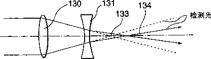
If utilize thermal lens to carry out photo-thermal conversion spectrum analysis method, then the focal position of exciting light must be different mutually with the focal position of detecting light.Fig. 3 A has shown at object lens to have the formation position of thermal lens under the situation of aberration and detect light focal position of (on Z-direction) on the excitation light direction of principal axis, and Fig. 3 B has shown at object lens do not have the formation position of thermal lens under the situation of aberration and detect light focal position of (on Z-direction) on the excitation light direction of principal axis.
If object lens 130 have aberration, then as shown in Figure 3A, 132 places, focal position at exciting light form thermal lens 131, and the focal position 133 of detection light has been offset a quantity Δ L with respect to the focal position 132 of exciting light, makes the focal length variations along with detection light can detect the variations in refractive index of thermal lens 131.On the other hand, if object lens 130 do not have aberration, then shown in Fig. 3 B, the position of the thermal lens 131 that the focal position 133 of detecting light almost forms with 132 places, focal position at exciting light is accurately identical.Therefore, thermal lens 131 does not reflect detection light, and therefore can not detect the variations in refractive index of thermal lens 131.
Yet, usually make microscopical object lens, make it not have aberration, therefore for the above reasons, the position accurately identical (Fig. 3 B) of the thermal lens 131 that the focal position 133 of detecting light almost forms with 132 places, focal position at exciting light makes the variations in refractive index that can not detect thermal lens 131.Therefore, there is following problem, when promptly measuring at every turn, the position that forms the sample of thermal lens 131 must be with respect to position 133 skews that detect light, shown in Fig. 4 A and 4B, otherwise must use the lens (not shown) to make before introducing in the object lens 130 to detect light to disperse slightly or assembles will detecting light, make the detection position 133 of detection light be offset, thereby cause user's work efficiency reduction with respect to thermal lens shown in Figure 5 131.
And, conventionally, in photo-thermal conversion spectrum analysis, also there not be to propose to be used for method with high-sensitivity detection light, this causes and can not design measurement sensitivity, therefore can not make to have stable high-performance microchemistry system.
Summary of the invention
The purpose of this invention is to provide a kind of photo-thermal conversion spectrum analysis method, it can analyze, measure and detect with high sensitivity, also relates to a kind of small size microchemistry system that is used to realize this method.
To achieve these goals, according to a first aspect of the invention, provide a kind of microchemistry system, it comprises: passage, sample flow are crossed this passage; Luminescent device, it sends two kinds of light with different wave length; Condenser, it is assembled the light that sends from luminescent device and form focus passage or near the position of passage; And checkout equipment, it detects send from luminescent device and light intensity that pass passage, and wherein the degree of depth of this passage is not less than the twice of two kinds of range differences between the focal position of not sharing the same light.
Utilize the configuration of first aspect present invention, the degree of depth of the passage that the sample flow that detect is crossed should can not obtain enough signal intensities thus less than the twice of the focal position difference between exciting light and the detection light, and therefore can be with the high-sensitivity detection sample.Therefore, can be to not measuring by the micro reaction that conventional method is measured.
Preferably, condenser has aberration.
According to above structure, condenser has aberration, thereby can omit the optical system that is used to adjust exciting light and detects the focal position of light, reduces the size of microchemistry system thus.
Preferably, condenser is a rod-shaped lens.
According to above structure, condenser is a rod-shaped lens, therefore can reduce the size of this condenser and also can more place near passage.Therefore, can further reduce the size of microchemistry system.
Preferably, the microchemistry system comprises optical fiber, and optical fiber is together with each other luminescent device and condenser.
According to above structure, optical fiber is directed to the light guide path of condenser with acting on exciting light and detection light, thereby there is no need to adjust the light path of exciting light and detection light when each enforcement is measured, and has improved user's work efficiency thus.In addition, there is no need to be provided for adjusting the anchor clamps of light path, thereby reduced the size of microchemistry system.If by independent Optical Fiber Transmission exciting light and detection light, then always make exciting light and detection only coaxial, thereby there is no need to be provided for adjusting the anchor clamps of optical axis, can further reduce the size of microchemistry system thus.
Preferably, optical fiber is single-mode fiber.
According to above structure, used single-mode fiber, therefore little and have a little aberration by the thermal lens size of excitation light generation, this is just feasible can to detect sample with higher precision.
In order to realize above purpose, according to a second aspect of the invention, provide a kind of photo-thermal conversion spectrum analysis method, may further comprise the steps: exciting light is shone on the fluid that will analyze with assembling, in this fluid, to form thermal lens; Shine on the thermal lens with will detecting optical convergence; And measure the detection light intensity that passes thermal lens, wherein the range difference between the focal position of exciting light and detection light is no more than half of fluid depth.
According to the more detailed description below in conjunction with accompanying drawing, above and other purpose of the present invention, feature and advantage will be clearer.
Description of drawings
Fig. 1 is the synoptic diagram of expression according to the entire infrastructure of the microchemistry system of the embodiment of the invention;
Fig. 2 is the view that is used to explain the thermal lens principle;
Fig. 3 A has represented to be used to explain at object lens to have under the situation of aberration, the formation position of thermal lens and the view that detects light focal position of (on Z-direction) on the excitation light direction of principal axis;
Fig. 3 B has represented to be used to explain at object lens do not have under the situation of aberration, the formation position of thermal lens and the view that detects light focal position of (on Z-direction) on the excitation light direction of principal axis;
Fig. 4 A has represented to be used to explain at thermal lens and has been formed on than the focal position of detecting light more under the situation near the position of object lens the formation position of thermal lens and the view that detects light focal position of (on Z-direction) on the excitation light direction of principal axis;
Fig. 4 B has represented to be used to explain at thermal lens and has been formed on than the focal position of detecting light under the situation of the position of object lens the formation position of thermal lens and the view that detects light focal position of (on Z-direction) on the excitation light direction of principal axis;
Fig. 5 is the view that is used for explaining the method for the variations in refractive index that detects conventional photo-thermal transformational analysis device thermal lens, and represented that thereby placing light path will detect light concavees lens becomes diverging light, therefore make the focal position situation farther that detects light apart from the focal position of exciting light;
Fig. 6 has represented that having used aberration be under the situation of condenser of 37 μ m, is formed on the relation between the signal intensity of channel depth in the disk shaped part and thermal lens; And
Fig. 7 has represented that having used aberration be under the situation of condenser of 20 μ m, is formed on the relation between the signal intensity of channel depth in the disk shaped part and thermal lens.
Embodiment
Now, with reference to the accompanying drawing of having represented the preferred embodiment of the present invention the present invention is described.
By unremitting research, the inventor had been found that and has been used for the photo-thermal conversion spectrum analysis method of microchemistry system, detects light intensity and depends on exciting light and detect focal position difference between the light and the relation between the channel depth.
Fig. 1 is the synoptic diagram of expression according to the entire infrastructure of the microchemistry system of the embodiment of the invention.In Fig. 1, this microchemistry system has optical fiber 10, and this optical fiber 10 has embedded lens (hereinafter being called " optical fiber 10 with lens ").Optical fiber 10 with lens has (upside as shown in fig. 1) insertion optical fiber 101 wherein from its rear end, to be used for transmitting exciting light and detection light according to the single mode mode.The end that insertion has the optical fiber 101 in the optical fiber 10 of lens links to each other with an end of the bar-shaped lens 102 of graded index.For the external diameter that makes optical fiber 101 equals the external diameter of the bar-shaped lens 102 of graded index, the lasso 103 that provides external diameter to equal the external diameter of the bar-shaped lens 102 of graded index makes it center on optical fiber 101.The position of optical fiber 101 is fixing by lasso 103, and the bar-shaped lens 102 of graded index and lasso 103 are fixed in the pipe 104.Herein, optical fiber 101 can closely contact mutually with the bar-shaped lens 102 of graded index, perhaps can have the gap between them.Optical fiber 10 with lens is fixed on the surface of disc-shaped part 20 of channel form, and is as described below, and it is arranged on the position in the face of the passage 204 that is formed on parts 20.Optical fiber 10 with lens can directly be bonded to the disc-shaped part 20 of channel form by cementing agent, perhaps fixes by anchor clamps.And the optical fiber 10 with lens can be according to fixing with the mode that the disk shaped part 20 of channel form separates by the anchor clamps (not shown).The example of cementing agent that the optical fiber 10 that can be used for having lens is bonded to the disc-shaped part 20 of channel form comprises organic binder bond, for example acroleic acid binding agent and epoxy adhesive, for example ultra-violet curing type, thermosetting type or biliquid curing type, and inorganic binder.Lens 102 are not limited to the bar-shaped lens of graded index, and are just passable as long as it has a predetermined aberration.
The bar-shaped lens 102 of graded index are transparent rod-shaped lens, and are configured to the position of the central shaft of refractive index from it along its longitudinal extension, along radially changing continuously.This rod-shaped lens is called the convergence optical transmit body, and it is configured to distance center wheelbase diametrically and provides from the approximate quadratic equation by r of refractive index n (r) for the position of r,
n(r)=n
0{1-(g
2/2)×r
2},
N wherein
0Be illustrated in the refractive index of central axis, g represents the quadratic distribution constant.
If total length z with the bar-shaped lens 102 of graded index
0Be chosen as 0<z
0The scope of<pi/2 g, even the bar-shaped lens 102 of graded index have planar end so, the bar-shaped lens 102 of this graded index also will have the imaging characteristic identical with common convex lens; When parallel beam incides on the bar-shaped lens 102 of this graded index, be s in the distance of the light beam exit end of the bar-shaped lens 102 of distance graded index
0The position will form focus, wherein
s
0=cot(gz
0)/n
0g。
Because the bottom surface of the bar-shaped lens 102 of graded index is planes, so these lens 102 can be attached to the end face of optical fiber 101 easily, and the optical axis of the optical axis of the bar-shaped lens 102 of graded index and optical fiber 101 can be aimed at easily mutually.And, because the bar-shaped lens 102 of this graded index are columns, also can form columnar shape easily so have the optical fiber 10 of lens.
Single-mode fiber is used as optical fiber 101, this is because utilizing photo-thermal conversion spectrum analysis method to detect under the situation of very small amount of solute in the sample, what wish to obtain is that exciting light narrows down as much as possible and is used for the energy of photothermal conversion with raising, and wishes to make the thermal lens that utilizes the exciting light manufacturing have little aberration.
Always have Gaussian distribution from the light of single-mode fiber 101 outgoing, so the size of the focus of exciting light is little.And, if little,, make also preferably that to detect light narrow as much as possible in order to make the detection light quantity of passing this thermal lens big as much as possible by the size of the thermal lens of excitation light generation.Also be for this viewpoint,, preferably propagate exciting light and detect light in the single mode mode for optical fiber.
As long as can transmit exciting light and detect light, the optical fiber of any type can be used as optical fiber 101.Yet if used multimode optical fiber, emergent light will not have Gaussian distribution, and the pattern of emergent light will be according to different conditions, and for example therefore the curvature state of optical fiber 101 and changing can not obtain stable emergent light.Therefore solute is very in a small amount measured difficulty, and the measured value deficient in stability.Therefore, for optical fiber 101, preferably aforesaid single-mode fiber.
If the end of guiding to of optical fiber is processed into sphere etc.,, can under the leading end of optical fiber is installed the situation of lens independently, exciting light be narrowed down so to form lens.Yet in this case, have any aberration hardly, so the focal position of exciting light and detection light almost is identical.Thereby there is the problem that almost can not detect the thermal lens signal.And for the lens that form by the leading end of handling optical fiber, therefore other aberration height also exists exciting light and the big problem of focus that detects light.Therefore in the present embodiment, the bar-shaped lens 102 of graded index are installed to the leading end of optical fiber 101.
The other end at optical fiber 101 provides excitation source 105, detection light source 106, has been used for exciting light of modulating the modulator 107 of excitation source and being used for multiplexed introducing optical fiber 101 and the dual wavelength multiplexing equipment 108 that detects light.Should be noted that utilize dichronic mirror to replace dual wavelength multiplexing equipment 108 can multiplexed exciting light and detect light, and therefore multiplexed light can be introduced in the optical fiber 101.
The disk shaped part 20 of the channel form that the sample that detects passes comprises mutually stacked three glass substrates 201,202 and 203, for example three layers and bond together.In glass substrate 202, form passage 204, when mix, stir, synthesize, sample passes this passage when separation, extraction, detection etc.
For permanance and chemical-resistant viewpoint, the material of the disk shaped part 20 of channel form is glass preferably.Especially, consider to be used for for example biological specimen of DNA analysis that for example cell preferably has highly-acidproof and high alkali-proof glass, particularly, borosilicate glass, soda-lime glass, alumina borosilicate glass, quartz glass etc.Yet if correspondingly define purposes, use organic material, for example plastics so can replace.
The example that can be used for cementing agent that glass substrate 201,202 and 203 is bonded together comprises organic binder bond, for example acroleic acid binding agent and epoxy adhesive, for example ultra-violet curing type, thermosetting type or biliquid curing type, and inorganic binder.Alternatively, can glass substrate 201,202 and 203 be fused together by heat fusing.
In the face of optical fiber 10 with lens and in the face of the position of passage 204 be provided for detecting light photoelectric commutator 401 and with exciting light with detect that light separate and only transmit detection light wavelength light filter 402 selectively.Can also be provided for selectively the parts that hop only detects light, it has the pin hole that is formed on wherein, makes this pin hole be arranged in the detection light light path of the position upstream of photoelectric commutator 401.
The signal that photoelectric commutator 401 is obtained sends to locks amplifier 404, thereby makes it synchronous with the modulator 107 that is used to modulate exciting light, and 405 pairs of these signals of computing machine are analyzed then.
The focal position of the exciting light that penetrates from the bar-shaped lens of graded index 102 is preferably placed at the passage 204 of disc-shaped part 20 of channel form.The bar-shaped lens 102 of this graded index need not contact with the disc-shaped part 20 of channel form, if but the bar-shaped lens 102 of this graded index contact with the disc-shaped part 20 of channel form, the thickness of the top glass substrate 201 of disc-shaped part 20 that so can be by channel form is adjusted the focal length of the bar-shaped lens 102 of graded index.If the thickness deficiency of top glass substrate 201 can be inserted into the escapement that is used to adjust focal length between bar-shaped lens 102 of graded index and the top glass substrate 201 so.
The bar-shaped lens 102 of graded index are set, focal position that make to detect light with respect to the focal position offset slightly of exciting light quantity Δ L (referring to Fig. 4 A).
Confocal length Ic (nm) is Ic=π * (d/2)
2/ λ
1Herein, d represents Airy dish and represented by d=1.22 * λ 1/NA, wherein λ
1Expression excites light wavelength (nm), and NA represents the numerical aperture of the bar-shaped lens 102 of graded index.Using under the situation of optical fiber, little from the numerical aperture of the light of optical fiber outgoing, therefore when having the rod-shaped lens of large-numerical aperture, use calculates the numerical aperture that needs to consider optical fiber in the process of confocal length.
When thickness was measured less than the sample of confocal length, highly preferred value Δ L was for equaling √ 3 * Ic.Value Δ L represents to detect focal position poor of the focal position of light and exciting light, and therefore the result is identical, and long still short no matter detect the focal length of focal distance ratio exciting light of light.
The degree of depth of the passage that is used for the microchemistry system 204 that forms in disk shaped part 20 is that 50 μ m are to 100 μ m.Reason is as follows.In the microchemistry system, mixing in the meticulous passage in being formed on disk shaped part, reaction, separation, extraction or test sample solution, therefore this microchemistry system compares with the general chemistry operation that utilizes beaker etc., have and to reduce employed sample size, to react the advantage of sample and minimizing plant bulk at a high speed.In these advantages in detail, the raising of reaction velocity will be described.What bring certain benefits in the reaction that utilizes the microchemistry system is the reaction of liquid one liquid surface, and wherein this reaction is undertaken by the interface.In this reaction, the reactant that is included in each solution is being in contact with one another at the interface, react thus.Only reacting at the interface, so reaction rate is the speed decision that can be reached this interface by every kind of reactant in each solution.Therefore, specific interfacial area (ratio of interface and liquor capacity) is important.In the microchemistry system, can form the interface along passage, therefore can provide very large specific interface area with reacting phase ratio in beaker etc.Therefore, can improve reaction velocity.In order to improve reaction velocity, importantly reduce the degree of depth of solution, i.e. width of channel apart from this interface by improving specific interfacial area.Yet, in methods such as wet etching as the method for in current microchemistry system, making passage, the aspect ratio of the passage that can the form ratio of the degree of depth (width of channel with) is limited, therefore, only can not be independent of the width of the degree of depth control channel of passage, but also need to reduce the degree of depth of passage, thereby width of channel is narrowed down.
According to above-mentioned situation, known that the degree of depth of passage should be littler, thereby improved reaction velocity.Yet, when the degree of depth of passage is too small, produced the problem that liquid can not keep the problem of its character in passage and be difficult to make the liquid admission passage.Therefore, the degree of depth is about 50 μ m and is used for many situations to the passage of 100 μ m.If under the situation that the solution that comprises the material that will detect flows in the passage of as above configuration, implement photo-thermal conversion spectrum analysis method, then the thickness of sample is very big for the confocal length of exciting light.For example, be that 0.25 object lens are assembled under the situation of exciting light that wavelength is 658nm at NA (numerical aperture), confocal length is that the thickness of 12.3 μ m and passage becomes 4 times that are not less than confocal length.When the material that will detect is thicker with respect to confocal length, produced and the stacked identical situation of situation of multilayer sample that approaches and form each thermal lens with respect to confocal length, therefore finally to become the integrated value of region area of the thermal lens that forms with thin sample the same big for the region area of the thermal lens that is formed by thick sample, thereby the optimum value of the focal position deviation between exciting light and the detection light is with to compare change when forming thermal lens by thin sample big when forming thermal lens by thick sample.
When use has the condenser of large focal spot position deviation, the focal position of exciting light and the focal position of detecting light be at a distance of bigger amount, so the result of photo-thermal conversion spectrum analysis and measurement has further experienced the influence of assembly on by the depth direction of the thermal lens that excites lens to form.Therefore, at photo-thermal conversion spectrum analysis with in measuring, employed channel depth is big more, and the signal intensity that is obtained is big more, therefore wishes to obtain bigger channel depth.Yet, as mentioned above,, wish to obtain littler channel depth according to the relation between reaction rate and the channel depth.Therefore, consider both of these case, what wish to obtain is the twice that the degree of depth of passage should be not less than aberration, more preferably is not less than three times, and aberration is that exciting light is poor with the focal position between the detection light.
Although below described the situation of making the isotropy passage by wet etching, when the method by being different from wet etching (for example, mechanical lapping, utilize the anisotropic etching of mask and dry etching) formation anisotropy passage.It is 10 * 10 along the cross-sectional area perpendicular to the plane of the microchemistry chip surface that forms the microchemistry system that the width of channel and the degree of depth also should be designed to passage
5μ m
2To 1.0 * 10
5μ m2.If the cross-sectional area of passage in above scope, can obtain to allow to be used as the reaction rate and the characteristic of the microchemistry chip that will show.
Although the inventor has had been found that in photo-thermal conversion spectrum analysis and measurement, the detection light intensity depends on focal position difference and the channel depth between exciting light and the detection light, but be used for aforesaid microchemistry system for photo-thermal being changed spectrum analysis and measurement, determine suitable channel depth according to the relation between channel depth and the reaction rate.In other words, must consider exciting light and detect light wavelength, channel depth and the situation of required these three factors of detected intensity under design microchemistry system.For the consideration of reaction rate aspect, preferably be used for the exciting light of this microchemistry system and detect light wavelength should be 400nm, and channel depth should be 50 μ m to 100 μ m to 1000nm.According to these conditions, in order to obtain enough detected intensity and enough reaction rates, most preferably the degree of depth of passage should be about exciting light and detect 2 to 4 times of focal position difference between the light.
Now, will the scope of the aberration that can utilize the bar-shaped lens acquisition of graded index be described by way of example.For example, Nippon Sheet Glass Co., the SELFOC that Ltd (NHTechno company) publishes
TMThe lens SLW that describes in the lens catalogue can be used as the bar-shaped lens of graded index.
When the material of the disc-shaped part of channel form is Pyrex (registered trademark) glass, the thickness (thickness of top glass 201) of passage top is 0.9mm, the degree of depth of passage is 0.1mm, the diameter of the bar-shaped lens SLW of graded index is 1mm, the length of rod-shaped lens is 2.3mm, and exciting light wavelength is 658nm, and detecting light wavelength is 785nm, the focal position of exciting light is positioned at the center of passage, and the focal position that is obtained poor (Δ L) is 37 μ m.
By measurement be formed in the disc-shaped part channel depth and with this rod-shaped lens as the results are shown among Fig. 6 that the relation between the signal intensity of the thermal lens of condenser obtains.These measurement results obtain under the following conditions.
As the sample that will measure, will be by with 10
-5Blue or green sulfonic acid four sodium (nickel-phthalocyanine tetrasodium sulfonate) of the concentration of mol/l dissolving nickel one phthaleinization and the aqueous solution that obtains places each passage that is formed on disc-shaped part and has each degree of depth, and measure under the immobilising situation of this aqueous solution keeping.Exciting light wavelength is 658nm, and the detection light wavelength is 785nm, and the modulating speed of exciting light is 1kHz, is fixed in the focal position of exciting light under the situation of channel center to measure.
As shown in Figure 6, the channel depth in being formed on disc-shaped part is 160 μ m or when bigger, signal intensity obtains maximal value, and this degree of depth is corresponding to about 4.3 times of the aberration of employed condenser.When the channel depth in being formed on disc-shaped part was 120 μ m (it is corresponding to about 3.2 times of the aberration of condenser), signal intensity became peaked 0.9 times.And when the channel depth in being formed on disc-shaped part was 75 μ m (it is corresponding to about 2 times of the aberration of condenser), signal intensity became peaked 0.6 times.
By with lens SLW and the bar-shaped combination of lenses of another graded index, can adjust the aberration of the bar-shaped lens SLW of above-mentioned graded index.By with these SLW lens with corresponding to NipponSheet Glass Co., the SELFOC that Ltd. publishes
TMThe combination of lenses of the SLA12 that describes in the lens catalogue, having prepared aberration is the condenser of 20 μ m, and utilize this condenser, the relation between the signal intensity that is formed on channel depth in the disc-shaped part and thermal lens is measured, and measurement result as shown in Figure 7.
As shown in Figure 7, the channel depth in being formed on disc-shaped part is 100 μ m or when bigger, signal intensity obtains maximal value, and this degree of depth is corresponding to about 5 times of the aberration of employed condenser.When the channel depth in being formed on disc-shaped part was 70 μ m (it is corresponding to about 3.5 times of the aberration of condenser), signal intensity became peaked 0.9 times.And when the channel depth in being formed on disc-shaped part was 40 μ m (it is corresponding to about 2 times of the aberration of condenser), signal intensity became peaked 0.5 times.
As knowing according to above measurement result, for the viewpoint that improves reaction rate, the channel depth that more preferably is used for the microchemistry system should be littler, but when making this degree of depth too small, exist the signal intensity of thermal lens to reduce, so the problem of detection sensitivity variation.Therefore, the degree of depth of passage should be not less than 2 times of aberration of condenser, and promptly therefore exciting light and detect 2 times of focal position difference between the light can make the signal intensity of thermal lens be not less than peaked 0.5 times.By the degree of depth of setting passage like this, can obtain to implement photo-thermal conversion spectrum analysis and measure required big detected intensity with high reaction rate.When analyzing or measuring with high reaction rate, perhaps when not needing high reaction rate to implement to analyze or measure, the channel depth that can be used in this microchemistry system is not less than the exciting light of condenser and three times of the focal position difference between the detection light.In this case, reaction rate is diminished slightly, but can make the signal intensity of thermal lens be not less than peaked 0.7 times, therefore can further strengthen detection sensitivity.
According to present embodiment, this disc-shaped part is provided with the passage of aberration that the degree of depth is suitable for use as the bar-shaped lens of graded index of condenser, therefore, can implement to measure with high sensitivity.And therefore the optical system that there is no need to be provided for independently to adjust exciting light or detect the focal position of light can reduce this device size.
The present invention can be used for detecting the microchemistry system of the sample reaction very in a small amount of flowing at meticulous passage, and the photo-thermal conversion spectrum analysis method that is used for this microchemistry system.
Claims (6)
1, a kind of microchemistry system, it comprises:
Passage, sample flow are crossed this passage;
Luminescent device, it sends two kinds of light with different wave length;
Condenser, it is assembled the described light that sends from described luminescent device and form focus described passage or near the position of described passage; And
Checkout equipment, it detects send from described luminescent device and described light intensity that pass described passage,
Wherein, the degree of depth of described passage is not less than the twice of two kinds of range differences between the focal position of not sharing the same light.
2, microchemistry according to claim 1 system, wherein, described condenser has aberration.
3, microchemistry according to claim 1 system, wherein, described condenser is a rod-shaped lens.
4, microchemistry according to claim 1 system comprises optical fiber, and wherein by described optical fiber described luminescent device and described condenser is together with each other.
5, microchemistry according to claim 4 system, wherein, described optical fiber is single-mode fiber.
6, a kind of photo-thermal conversion spectrum analysis method may further comprise the steps:
Exciting light is shone on the fluid to be analyzed with assembling, in this fluid, to form thermal lens;
Shine on the described thermal lens with will detecting optical convergence; And
The described detection light intensity of described thermal lens is passed in measurement,
Wherein, the range difference between the focal position of described exciting light and described detection light is no more than half of the degree of depth of described fluid.
Applications Claiming Priority (2)
| Application Number | Priority Date | Filing Date | Title |
|---|---|---|---|
| JP150828/2004 | 2004-05-20 | ||
| JP2004150828A JP2005331407A (en) | 2004-05-20 | 2004-05-20 | Photothermal conversion spectral analyzing method and microchemical system for performing the same |
Publications (1)
| Publication Number | Publication Date |
|---|---|
| CN1699972A true CN1699972A (en) | 2005-11-23 |
Family
ID=35374843
Family Applications (1)
| Application Number | Title | Priority Date | Filing Date |
|---|---|---|---|
| CN200510072857.5A Pending CN1699972A (en) | 2004-05-20 | 2005-05-20 | Photothermal conversion spectroscopic analysis method and microchemical system for implementing the method |
Country Status (3)
| Country | Link |
|---|---|
| US (1) | US20050259259A1 (en) |
| JP (1) | JP2005331407A (en) |
| CN (1) | CN1699972A (en) |
Cited By (2)
| Publication number | Priority date | Publication date | Assignee | Title |
|---|---|---|---|---|
| CN101893571A (en) * | 2009-05-19 | 2010-11-24 | 日本板硝子株式会社 | Optical wavelength demultiplexing detector for fluorescence analysis and fluorescence detecting system |
| CN105510234A (en) * | 2015-12-31 | 2016-04-20 | 合肥知常光电科技有限公司 | Optical fiber sensing-based laser excitation heat wave signal detection device |
Families Citing this family (2)
| Publication number | Priority date | Publication date | Assignee | Title |
|---|---|---|---|---|
| JP3824224B2 (en) * | 2002-09-27 | 2006-09-20 | 日本板硝子株式会社 | Micro chemical system |
| AU2021210823A1 (en) * | 2020-01-22 | 2022-07-21 | Nicoya Lifesciences, Inc. | Digital microfluidic (DMF) system, DMF cartridge, and method including integrated optical fiber sensing |
Family Cites Families (6)
| Publication number | Priority date | Publication date | Assignee | Title |
|---|---|---|---|---|
| WO1992007245A1 (en) * | 1990-10-10 | 1992-04-30 | The University Of Maryland | Method and apparatus for performing phase fluorescence lifetime measurements in flow cytometry |
| US5121405A (en) * | 1990-12-20 | 1992-06-09 | Coherent, Inc. | Alignment control system for lasers |
| JP2003021704A (en) * | 2001-07-10 | 2003-01-24 | Nippon Sheet Glass Co Ltd | A pair of refractive index distributed rod lenses and microchemical system equipped with the lenses |
| JP2003042982A (en) * | 2001-07-27 | 2003-02-13 | Nippon Sheet Glass Co Ltd | Photothermal conversion spectroscopy method and microchemical system for performing the method |
| US6760356B2 (en) * | 2002-04-08 | 2004-07-06 | The Regents Of The University Of California | Application of Yb:YAG short pulse laser system |
| JP2003344323A (en) * | 2002-05-30 | 2003-12-03 | Nippon Sheet Glass Co Ltd | Photothermal conversion spectroscopic analysis method and photothermal conversion spectroscopic analyzer implementing the method |
-
2004
- 2004-05-20 JP JP2004150828A patent/JP2005331407A/en active Pending
-
2005
- 2005-05-18 US US11/132,892 patent/US20050259259A1/en not_active Abandoned
- 2005-05-20 CN CN200510072857.5A patent/CN1699972A/en active Pending
Cited By (3)
| Publication number | Priority date | Publication date | Assignee | Title |
|---|---|---|---|---|
| CN101893571A (en) * | 2009-05-19 | 2010-11-24 | 日本板硝子株式会社 | Optical wavelength demultiplexing detector for fluorescence analysis and fluorescence detecting system |
| CN101893571B (en) * | 2009-05-19 | 2014-07-23 | 日本板硝子株式会社 | Optical wavelength demultiplexing detector for fluorescence analysis and fluorescence detection system |
| CN105510234A (en) * | 2015-12-31 | 2016-04-20 | 合肥知常光电科技有限公司 | Optical fiber sensing-based laser excitation heat wave signal detection device |
Also Published As
| Publication number | Publication date |
|---|---|
| US20050259259A1 (en) | 2005-11-24 |
| JP2005331407A (en) | 2005-12-02 |
Similar Documents
| Publication | Publication Date | Title |
|---|---|---|
| US7444053B2 (en) | Integrated electrical and optical sensor for biomolecule analysis with single molecule sensitivity | |
| US6316781B1 (en) | Microfluidic devices and systems incorporating integrated optical elements | |
| CN1267753C (en) | Refractive index profile type rod lens unit and micro-chemical system provided with the unit | |
| US20110036992A1 (en) | Light detection device | |
| JP3969699B2 (en) | Chip member for microchemical system, and microchemical system using the chip member | |
| US6930778B2 (en) | Microchemical system | |
| TWI305834B (en) | Chip element for microchemical systems , and microchemical system using the chip element | |
| CN1575414A (en) | Microchemical system, and photothermal conversion spectroscopic analysis method | |
| CN1699972A (en) | Photothermal conversion spectroscopic analysis method and microchemical system for implementing the method | |
| US7012692B2 (en) | Photothermal conversion spectroscopic analysis method, and photothermal conversion spectroscopic analysis apparatus for carrying out the method | |
| CN211603214U (en) | Grating waveguide microfluid detection system | |
| US7057729B2 (en) | Photothermal conversion spectroscopic analysis method, and photothermal conversion spectroscopic analysis apparatus for carrying out the method | |
| US20040071597A1 (en) | Chip member for micro chemical system, and micro chemical system using the chip member | |
| US7092099B2 (en) | Microchemical system and photothermal conversion spectroscopic analysis method implemented by the system | |
| KR20030080934A (en) | Micro Measurement System for Bio Fluorescence Measurement | |
| CN211826084U (en) | Grating waveguide microfluid detection system | |
| JP2004020262A (en) | Photothermal conversion spectroscopic method and apparatus therefor | |
| JP2004309270A (en) | Micro chemical system | |
| JP2003194751A (en) | Micro chemical system | |
| CN111157732A (en) | Grating Waveguide Microfluidic Detection System | |
| Lee et al. | Design and fabrication of miniaturized fluorescence detection system for protein samples | |
| BRPI0913786B1 (en) | DETECTION SYSTEM AND DETECTION METHOD |
Legal Events
| Date | Code | Title | Description |
|---|---|---|---|
| C06 | Publication | ||
| PB01 | Publication | ||
| C02 | Deemed withdrawal of patent application after publication (patent law 2001) | ||
| WD01 | Invention patent application deemed withdrawn after publication |