JP2005326006A - High pressure closing device - Google Patents
High pressure closing device Download PDFInfo
- Publication number
- JP2005326006A JP2005326006A JP2005134485A JP2005134485A JP2005326006A JP 2005326006 A JP2005326006 A JP 2005326006A JP 2005134485 A JP2005134485 A JP 2005134485A JP 2005134485 A JP2005134485 A JP 2005134485A JP 2005326006 A JP2005326006 A JP 2005326006A
- Authority
- JP
- Japan
- Prior art keywords
- door
- ring
- hub
- actuator member
- closure device
- Prior art date
- Legal status (The legal status is an assumption and is not a legal conclusion. Google has not performed a legal analysis and makes no representation as to the accuracy of the status listed.)
- Withdrawn
Links
Images


Classifications
-
- F—MECHANICAL ENGINEERING; LIGHTING; HEATING; WEAPONS; BLASTING
- F17—STORING OR DISTRIBUTING GASES OR LIQUIDS
- F17C—VESSELS FOR CONTAINING OR STORING COMPRESSED, LIQUEFIED OR SOLIDIFIED GASES; FIXED-CAPACITY GAS-HOLDERS; FILLING VESSELS WITH, OR DISCHARGING FROM VESSELS, COMPRESSED, LIQUEFIED, OR SOLIDIFIED GASES
- F17C13/00—Details of vessels or of the filling or discharging of vessels
- F17C13/06—Closures, e.g. cap, breakable member
-
- F—MECHANICAL ENGINEERING; LIGHTING; HEATING; WEAPONS; BLASTING
- F16—ENGINEERING ELEMENTS AND UNITS; GENERAL MEASURES FOR PRODUCING AND MAINTAINING EFFECTIVE FUNCTIONING OF MACHINES OR INSTALLATIONS; THERMAL INSULATION IN GENERAL
- F16J—PISTONS; CYLINDERS; SEALINGS
- F16J13/00—Covers or similar closure members for pressure vessels in general
- F16J13/02—Detachable closure members; Means for tightening closures
- F16J13/12—Detachable closure members; Means for tightening closures attached by wedging action by means of screw-thread, interrupted screw-thread, bayonet closure, or the like
-
- F—MECHANICAL ENGINEERING; LIGHTING; HEATING; WEAPONS; BLASTING
- F16—ENGINEERING ELEMENTS AND UNITS; GENERAL MEASURES FOR PRODUCING AND MAINTAINING EFFECTIVE FUNCTIONING OF MACHINES OR INSTALLATIONS; THERMAL INSULATION IN GENERAL
- F16L—PIPES; JOINTS OR FITTINGS FOR PIPES; SUPPORTS FOR PIPES, CABLES OR PROTECTIVE TUBING; MEANS FOR THERMAL INSULATION IN GENERAL
- F16L55/00—Devices or appurtenances for use in, or in connection with, pipes or pipe systems
- F16L55/10—Means for stopping flow from or in pipes or hoses
- F16L55/11—Plugs
- F16L55/1108—Plugs fixed by screwing or by means of a screw-threaded ring
Abstract
Description
本発明は、圧力収容の容器又はパイプラインの内部部分を選択的に閉鎖し密閉する容器又はパイプラインの閉鎖装置に関する。より特別には、本発明は、パイプラインにおけるピッグの発射及び回収システムに使用される形式の閉鎖装置及び加圧された容器のアクセス用ポータルの閉鎖装置に関する。 The present invention relates to a container or pipeline closure device for selectively closing and sealing an internal portion of a pressure-accommodating container or pipeline. More particularly, the invention relates to a closure device of the type used in a pig launching and retrieval system in a pipeline and a closure device for a pressurized container access portal.
閉鎖装置は、圧力収容容器の、その内部へのアクセスを提供するアクセスポートを選択的に閉鎖する。閉鎖装置のよりしばしば使われる用途の一つは、パイプラインにおいて、パイプラインの清掃及び検査に使用される「ピッグ」を発射しかつ回収するためである。歴史的に最も多い作業は34.48MPa(5000psi)以下の作動圧力を使用した。近年は、石油産業部門がより高圧の閉鎖装置の使用を要求している。 The closure device selectively closes the access port of the pressure containment vessel that provides access to the interior thereof. One of the more frequently used applications of closure devices is to launch and retrieve “pigs” used in pipelines for pipeline cleaning and inspection. The most historical work used operating pressures of 34.48 MPa (5000 psi) or less. In recent years, the oil industry sector has demanded the use of higher pressure closure devices.
閉鎖装置のデザインは、通常、次の3グループ、即ちねじ式、クランプ式、又は平扉式の一つである。各方式は次の3個の基本的部品を持つ。1)容器又はパイプラインに永久的にかつ密閉して固定されるハブ部分、2)ハブに対する封鎖を提供する扉、及び3)扉のヒンジ又は輸送機構。 The design of the closure device is usually one of the following three groups: screw type, clamp type or flat door type. Each system has the following three basic parts. 1) a hub portion that is permanently and hermetically secured to a container or pipeline, 2) a door that provides a seal to the hub, and 3) a door hinge or transport mechanism.
ねじ式の閉鎖装置は、操作が煩わしくなる可能性がある。ハブの上にキャップをねじ込むことは直径が大きくなるので困難が大きくなる。寸法のあまり大きくないキャップでもクレーン又はデビッド式のヒンジ機構によりハブに関節式に取り付けられることが普通である。ねじ又はシール面の腐食が作業を困難にし、ひどい場合は不可能にすることもあり得る。しかし、ねじ式の閉鎖装置は、現場における大量の実際の使用により証明されるように簡単かつ安全なデザインを提供するため一般的である。特許文献1はねじ式の閉鎖装置を開け又は閉めるようにこれを回転させるためのチェーンバインダーを有するねじ式閉鎖装置の例を明らかにする。チェーンバインダーは、閉鎖装置を閉じるためにハンマーで叩かねばならない通常のハンマーラグに代わるものである。特許文献2はハンマーラグに代わる別の方法を開示し、これにおいては、閉鎖装置キャップにトルクを加えるために締め付け用の耳が使用される。特許文献3、特許文献4、特許文献5、特許文献6、及び特許文献7は、種々の平形の扉閉鎖装置を明らかにする。ASMEでは、「非固定平頭及びカバーの認め得る幾つかの形式(Some Acceptable Types of Unstayed Flat Heads and Covers)を示している図を出版した。これはねじによりハブに固定されかつ扉から構造的に分離した固定用リングを含む概念的閉鎖装置の線図を示している。平扉のものは3形式の最速のアクセスを提供する。しかし、これはその重量が取り付けを難しくし、かつ長期にわたる腐食が操作を妨げる。複雑な封鎖方法も必要である。平扉は、通常、自己ヒンジ式又は持ち上げ式の装置でハブに確保される。
Screw-type closure devices can be cumbersome to operate. Screwing the cap onto the hub increases the difficulty due to the increased diameter. It is common for caps that are not too large to be articulated to the hub by a crane or David hinge mechanism. Corrosion of the screw or sealing surface can make the operation difficult and, in severe cases, impossible. However, screw-type closure devices are common because they provide a simple and safe design as evidenced by the large amount of actual use in the field. U.S. Pat. No. 6,057,089 clarifies an example of a screw-type closure device having a chain binder for rotating the screw-type closure device to open or close. Chain binders are an alternative to the usual hammer lugs that must be hammered to close the closure device. U.S. Pat. No. 6,057,834 discloses another alternative to hammer lugs, in which a clamping ear is used to apply torque to the closure device cap. Patent Literature 3, Patent Literature 4,
クランプ式閉鎖装置は、2個のフランジを一緒に合わせ、次いで外側の環状固定用リング配列によりこれらの位置を確保することにより機能する。通常、環状の固定用リングは、2個のセグメントで与えられ、これらセグメントはボルト止め式の配列により互いに保持される。概念は単純であるが、この閉鎖装置は重くかつ取り扱い及び封鎖が困難である。扉は、閉鎖装置の永久部分の何かの取り扱い/関節結合が必要であるだけでなく、固定用リング自体も扱いが難しい。かかる器具を固定するには、通常、何かの形の動力付き装置が必要である。大きな一つの阻害は、作業員に明らかでない圧力の存在である。圧力の作動下における破局的な失敗及び扉が開けられた場合は死傷事故が生じた。クランプ式封鎖体が特許文献8に明らかにされる。
多種の閉鎖装置が使用されているが、これらの幾つかは、もしあれば、石油産業においてよりしばしば要求される高圧で作動するように設計される。従って、より高い圧力及び信頼性の大きい閉鎖装置が望まれる。 A variety of closure devices are used, some of which, if any, are designed to operate at the high pressures that are more often required in the oil industry. Therefore, a higher pressure and more reliable closure device is desired.
好ましい実施例により、容器のポートを密閉閉鎖する閉鎖装置及び方法が明らかにされる。ハブは、ハブ中心軸線を定めかつポートと連通する円穴を持つ。ハブには、一般にハブ中心軸線を中心とするねじが設けられる。ハブの末端とは軸方向反対側にある直近端部がポートの周りで容器に封着される。扉は、ハブの円穴の中で可動であり、かつ円穴の中に緩く位置決めすることができる。扉を着座させるためにハブにショルダーが設けられ、扉がショルダーに着座したとき、扉とハブとの間をシールが周囲で封鎖する。固定用リングは、リング中心軸線及びリング中心軸線を回る一般に同中心のリングねじを持つ。これにより、リングねじは、ハブねじと組み合うことができ、かつ固定用リングをリング中心軸線を回って回転させたとき、扉をショルダーに当たる閉鎖位置に動かせるように扉に関して回転可能でありかつ扉と軸方向で組み合うことができる。歯車又は回転可能な摩擦部材となし得る少なくも1個の回転可能なアクチュエーター部材が固定用リングと組み合い、かつアクチュエータ部材ーは、これが固定用リングを回転させるように、リング中心軸線から間隔を空けられた回転軸線を持つ。 The preferred embodiment reveals a closure device and method for hermetically closing a container port. The hub has a circular hole that defines a hub central axis and communicates with the port. The hub is generally provided with a screw centered on the hub central axis. The immediate end, which is axially opposite the end of the hub, is sealed to the container around the port. The door is movable in the hub's circular hole and can be loosely positioned in the circular hole. A hub is provided with a shoulder for seating the door, and when the door is seated on the shoulder, a seal seals between the door and the hub. The locking ring has a ring center axis and a generally concentric ring screw that rotates about the ring center axis. This allows the ring screw to be combined with the hub screw and is rotatable relative to the door so that the door can be moved to a closed position against the shoulder when the locking ring is rotated about the ring center axis. Can be combined in the axial direction. At least one rotatable actuator member, which can be a gear or a rotatable friction member, is combined with the locking ring and the actuator member is spaced from the ring center axis so that it rotates the locking ring. With a specified rotation axis.
ある実施例においては、複数の歯を、リング中心軸線を回って周囲に配列することができ、更に少なくも1個の回転可能なアクチュエーター部材は、複数の歯と組み合って固定用リングを回転させるための少なくも1個の歯車を備える。別の実施例においては、摩擦面がリング中心軸線を回って周囲に配列され、更に回転可能なアクチュエーター部材は、リングの摩擦面と摩擦で組み合うための摩擦部材を備え、摩擦部材の回転が固定用リングを回転させる。 In some embodiments, a plurality of teeth can be arranged around the ring center axis, and at least one rotatable actuator member can be combined with the plurality of teeth to rotate the locking ring. For at least one gear. In another embodiment, the friction surface is arranged around the ring center axis and the rotatable actuator member comprises a friction member for frictional engagement with the friction surface of the ring, the rotation of the friction member being fixed. Rotate the ring.
歯車、摩擦部材、又はその他の回転可能なアクチュエーター部材は、固定用リングの内向き面の半径方向内側に位置決めされ、かつ扉に回転可能に確保されることが好ましい。トルクを受け取りこれを少なくも1個の回転可能なアクチュエーター部材に伝えるために、少なくも1個の回転可能なアクチュエーター部材にソケット部材を固定することが好ましい。 A gear, friction member, or other rotatable actuator member is preferably positioned radially inward of the inward surface of the locking ring and secured to the door for rotation. In order to receive torque and transmit it to at least one rotatable actuator member, it is preferred to secure the socket member to at least one rotatable actuator member.
扉をハブ内に動かし又はハブから出すために、扉をハブに確保するための可動の取り付け用アームを設けることができる。 A movable mounting arm can be provided to secure the door to the hub to move the door into or out of the hub.
好ましい方法により、ハブの中心軸線を定める円穴、ハブに確保されかつ一般にハブの中心軸線を中心とするハブねじ、直近端部、直近端部と軸方向反対側の末端、及び扉が着座するためのハブ内のショルダーを有するハブが提供される。ハブの直近端部は、円穴とポートとが連通するようにポートの周りで容器に封着される、扉は、円穴の中で扉を除去し得るように位置決めされる。扉との封鎖のために円穴の中にショルダーが設けられる。リング中心軸線、及びリング中心軸線を一般に中心としたリングねじを有する固定用リングがハブねじと組み合わせられる。アクチュエーター部材の回転軸線がリング中心軸線から間隔を空けられた状態で、少なくも1個の回転可能なアクチュエーター部材が固定用リングに組み合わせられる。アクチュエーター部材は、固定用リングが軸方向で扉と組み合いかつ扉をショルダーと当たる閉鎖位置に動かすように、固定用リングをリング中心軸線を回って回転させる。扉とハブとは、扉がショルダーに着座したとき、周囲で封鎖される。 The preferred method seats a circular hole defining the central axis of the hub, a hub screw secured to the hub and generally centered on the central axis of the hub, a proximal end, an end axially opposite the proximal end, and a door. A hub having a shoulder in the hub for providing is provided. The proximal end of the hub is sealed to the container around the port so that the circular hole communicates with the port. The door is positioned so that the door can be removed within the circular hole. A shoulder is provided in the circular hole for sealing with the door. A fixing ring having a ring center axis and a ring screw generally centered on the ring center axis is combined with a hub screw. With the rotation axis of the actuator member spaced from the ring center axis, at least one rotatable actuator member is combined with the locking ring. The actuator member rotates the locking ring about the center axis of the ring so that the locking ring is axially assembled with the door and moved to a closed position where it hits the shoulder. The door and the hub are sealed around when the door is seated on the shoulder.
ある実施例においては、摩擦を減らすために、幾つかの運動部品に減摩塗装を行うことができる。 In some embodiments, some moving parts can be anti-friction coated to reduce friction.
以上は、本発明の一般的理念を与えることを意図したものであり、本発明を完全に定めることも限定することも意図しない。本発明は、以下の説明及び図面を参照し完全に理解されかつより良く認識されるであろう。 The foregoing is intended to give a general idea of the invention and is not intended to fully define or limit the invention. The present invention will be more fully understood and better understood with reference to the following description and drawings.
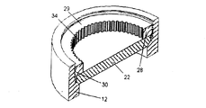
図1は、図10に示された容器7のポート5を密閉閉鎖するための閉鎖装置10の好ましい実施例を示す。容器7は、パイプライン、静圧容器、又はその他の形式の容器とすることができる。図2−5は、種々の等級の組立体における閉鎖装置10の種々の構成要素をより詳細に示す切断図である。ハブ12は円穴14を有し、この円穴はハブ中心軸線を定めかつポート5と連通する。ハブ12はポート5にハブ12をボルト止めするためのフランジ11を有するが、他の実施例においては、ハブ12は容器7に溶接又はその他で固定し密閉することができる。一般にハブ中心軸線を中心としたハブねじ16がハブ12に設けられる。ポート5の周りで容器7を密閉するために容器に直近端部18が設けられ、更に直近端部18の軸方向反対側に末端20がある。
FIG. 1 shows a preferred embodiment of a
扉22がハブ12の円穴の中で動くことができる。ハブ12内のショルダー24に扉22が着座する。図1−4は、ショルダー24に対して直接座った扉22を示し、これは、以下説明されるように、閉鎖位置にあるとき、潜在的に、扉22とショルダー24との間の金属−金属の封鎖を提供することができる。より好ましくは、扉22がショルダー24に座ったとき、図5に概念的に示されたように、弾性体シール26が扉22とハブ12のショルダー24との間で周囲の封鎖をする。シール26は、Oリング、リップシール、又は金属−金属封鎖用の金属リングのような本技術において一般に知られる種々の形式のシールの一つとすることができる。更に別の実施例においては、Oリング又はその他の形式のシールが、ショルダー24上における位置決めの必要なしに、扉22とショルダー24との間の周囲の封鎖をすることができる。シールは、圧力下で弾性変形又は塑性変形のどちらかをする圧縮シールとすることができる。シールは、U字形断面が容器内の圧力により開かれて封鎖する一般にU字形断面を有するリップシールのように圧力容器7による圧力により活性化させることもできる。弾性シールは、一般に、低圧においてより許されるシールを提供するが、金属シールは柔らかいポリマー混合物を損傷させる可能性のある高圧に対してより適している。
The
リング中心軸線及び一般にリング中心軸線を中心とするリングねじ30を有する固定用リング28が、ハブねじ16と組み合うことができる。リング中心軸線を回って固定用リング28を回転させたとき、図4及び5に示されるように扉22をショルダー24に押し付けられた閉鎖位置に動かすために、固定用リング28は、扉22と相対回転ができかつ扉22と軸方向で組み合うことができる。
A fixing
図8は、リング22がハンドル50を使用して手動で回される閉鎖装置10の実施例を示す。これは、より小型及び/又はより低圧の閉鎖装置には適しているが、この方法ではより大きい閉鎖装置を操作するのは困難なことがある。閉鎖装置を確実に閉鎖するため、リング22は、手によってなし得るよりも、より強く回す必要がある。高い内部圧力、大きい封鎖力、及び時間経過により腐食した部品のような要因が、リング22を回転させる困難を増大させる。動力付きの工具、又は少なくも単にハンドル50によるよりもより大きい力を出し得る工具により駆動し得る駆動システムが好ましい。
FIG. 8 shows an embodiment of the
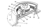
図1−5の閉鎖装置10は、好ましい「歯車駆動」の実施例である。複数の歯34がリング中心軸線を中心として周囲に配列される。少なくも1個の回転可能なアクチュエーター部材、この実施例においては3個の歯車32が、固定用リング28の歯34と組み合う。これら歯車32は、その回転が固定用リング28を回転させるようにリング中心軸線から間隔を空けられた回転軸線を持つ。
The
図9に示された別の「摩擦駆動」の実施例においては、摩擦面134がリング中心軸線を中心として周囲に配置される。回転可能なアクチュエーター部材が複数の摩擦部材132を備える。これら摩擦部材は、リング28の摩擦面134と摩擦で組み合うための歯のない「歯車」になぞらえられる。摩擦面134は剥き出しの金属とすることができるが、摩擦面134と摩擦部材132との間の摩擦係数を大きくするために粗面又は処理された面であることが好ましい。例えば、摩擦面134をローレット掛けし、カーバイド又はダイヤモンド砂を染み込ませ、或いは高摩擦ポリマー材料で被覆することができる。摩擦部材132は、リング28の摩擦面134と強制的に組み合わせられ、摩擦面134と摩擦部材132との間の適切な摩擦力を保持し滑りを防止することが好ましい。
In another "friction drive" embodiment shown in FIG. 9, a
図1に(及び同様に図5に)示されるように、歯車32は、固定用リング28の内向き面(この面は図1において歯34により定められた面)の半径方向内側に位置決めされることが好ましい。歯車32は、扉22及びハブ12の一方により支持され、好ましくは取り付け用ボルト39、スピンドル、又はその他のハードウエアにより扉22に回転可能に固定される。歯車32の取り付けに使用される取り付け用ボルト39又はその他のハードウエアは、歯車32の回転を許すが歯車32の横方向の動きは拘束すべきである。歯車32は、扉22に確保されているので、リング28との確りした係合状態で支持され、滑りの最小な又は滑りなしの信頼し得る回転方向の組み合いを確保することができる。摩擦駆動の実施例においては、摩擦部材132とリング28との間の確実な組み合いが特に重要である。更に、示されたような複数の歯車32の使用は、リング28に対する一様な外向きの力を提供して、リング28の安定化を助けることによりこの支持を増強させる。
As shown in FIG. 1 (and also in FIG. 5), the
図示された幾つかの実施例においては、歯34は半径方向内側に置かれたが、ある種の実施例は、半径方向外側に置かれた歯車を有し、外側に位置決めされたリングの歯を備えることができる。例えば、図12において、少なくも1個の回転可能なアクチュエーター部材332の1個が、半径方向外側でかつ外向きの面333又は固定用リング328の歯と組み合って位置決めされる。
In some of the illustrated embodiments, the
更に、図11に示されるように、1個又はそれ以上の回転可能なアクチュエーター部材332の回転軸線がリングの中心軸線を横切ることができる。図11においては、回転可能なアクチュエーター部材332の1個の回転軸線がリングの中心軸線と実質的に直交し、そしてアクチュエーター部材332は面334又は歯と組み合う。かかる別の実施例においては、回転可能なアクチュエーター部材は、構造335に確保される。構造335は扉に確保されて示されるが、閉鎖装置の別の部分に確保されるように変更することができる。
Further, as shown in FIG. 11, the rotational axis of one or more
歯車32に及び回転可能な摩擦部材132にソケット部材38が固定される。ソケット部材は、トルクを受け入れ、これを歯車32及び摩擦部材132に伝達する。ソケット部材38を回転させるためにブレーカバー(図示せず)を組み合っているソケットに取り付けることができる。特に大きくて重い閉鎖装置の場合は、ソケット部材38を駆動するためにインパクトレンチを使用することもできる。
A
図1に示されるように、可動の取り付け用アーム40が扉22をハブ12に確保する。アーム40は,扉22をハブ12内に又はハブ12から選択的に動かし得るように1個又はそれ以上のヒンジ42を備えることができる。リング28がハブ12にねじ結合されかつ扉22が固定用の位置にあるとき、リング28とハブ12とのねじ結合によりリング28と扉22とは閉鎖装置10に保持される。歯車32(及び図8における摩擦部材132)に保持器フランジ36が固定され、次に閉鎖装置10を開くときに固定用リング28を扉22の付くに保持するように固定用リング28の末端29と組み合う。歯車32は扉22に回転可能に確保されているので、リング28は、扉22とフランジ36との間に保持される。この保持は、これにより扉22とリング28とが取り付け用アーム40を介して円穴14の中で定位置に又は定位置からヒンジにより旋回できるため、閉鎖装置10、特に重い閉鎖装置の操作を容易にするために重要である。
As shown in FIG. 1, a movable mounting
図1の実施例においては、リングねじは雄ねじ30であり、ハブねじは雌ねじ16である。固定用リング28の全体は、扉22が閉鎖位置にあるとき、ハブ12の円穴14内に位置決めされる。対比して、図6及び7は閉鎖装置10の変更された2種の実施例を示し、これらにおいては、リング128、228のリングねじは雌ねじ130、230であり、ハブねじは雄ねじ116、216である。図6においては、リング128は内側の壁115の半径方向内向側に伸び、扉122は、扉122が閉鎖位置にあるとき、リング128が円穴114内に伸びることなく扉122と組み合うように、軸方向で円穴114からハブ12の末端120より先に伸びる。図7においては、リング228も内側の壁215の半径方向内向側に伸びるが、図6の扉122とは対照的に扉222は、全体が円穴214の中に置かれ、かつ内側の壁215の半径方向内側でリング228に固定されたスリーブ245が円穴214の中に伸び、扉222を閉鎖位置に動かす。
In the embodiment of FIG. 1, the ring screw is a
扉22、122、222は、平坦な円形板として示される。事実、これは製造の簡単な信頼し得る扉デザインである。例えば、円形板は、鋳造し、鍛造し、又は円形の棒材から切り出すことができる。しかし、実際は、扉は、ハブと周囲でシールされかつリングと組み合うことができる限り、単なる平板である必要はない。代わりに、扉はドーム状、又はある特定のハブと適合する特別な用途のために要求されるその他の形のようなより複雑な形状を取ることができる。ハブ12のようなハブは、円筒状の管又はパイプから製造できかつ典型的な円形ポート5とうまく組み合う一般的な円形OD及び円穴14を持つことが普通である。
The
摩擦は、摩擦面134と摩擦部材132との間の摩擦係合を提供するようなある実施例のある部品間では有利であるが、歯車32のような多くの運動部品は減摩塗料による利益を得ることができる。減摩塗料は本技術において知られる多くの材料を含むことができる。例えば、摩擦を減らしかつ回転の効率を上げるために、歯車32にポリマー性塗料を与えることができる。
While friction is advantageous between certain parts of certain embodiments that provide frictional engagement between the
本発明の特別の実施例がここに詳細に説明されたが、これは単に本発明の主な態様の説明の目的で行われたものであり、特許請求の範囲に定められた本発明の範囲を限定することを意図したものではない。本技術の熟練者は、図示され説明された実施例は例示のものであり、本発明の実行の際、本発明の範囲から離れることなく、ここに特別に説明されたこれら設計の変更例を、限定するためではなく含んだ種々のその他の置換、変更及び変化をなし得ることを理解するであろう。 Although specific embodiments of the present invention have been described in detail herein, this was done merely for the purpose of illustrating the principal aspects of the invention and the scope of the invention as defined in the claims. It is not intended to limit. Those skilled in the art will appreciate that the illustrated and described embodiments are exemplary and that, in carrying out the present invention, these specific design modifications described herein without departing from the scope of the present invention. It will be understood that various other substitutions, modifications and changes may be made, including but not limited to.
5 ポート
7 容器
10 閉鎖装置
12 ハブ
14 円穴
18 直近端部
20 末端
22 肩
24 ショルダー
28 固定用リング
30 リングネジ
5 Port 7
Claims (30)
ハブ中心軸線を定めポートと連通するための円穴、ハブに確保されかつほぼハブ中心軸線を中心とするハブねじ、ポートの周りで容器に封着するための直近端部、及び直近端部と軸方向反対側の末端を有するハブ、
ハブの円穴の中で動き得る扉、
扉が着座するためのハブ内のショルダー、
扉がショルダーに着座したとき、扉とハブとの間を周囲で封鎖するシール、
リング中心軸線及びほぼリング中心軸線を中心としたリングねじを有する固定用リングであって、リングねじはハブねじと組み合い可能であり、リング中心軸線を回る固定用のリングの回転の際、扉をショルダーに押し付けた閉鎖位置に動かすために扉に関して回転可能でありかつ扉と軸方向で組み合い得る前記固定用リング、及び
固定用リングと組み合っている少なくも1個の回転可能なアクチュエーター部材であって、アクチュエーター部材の回転が固定用リングを回転させるようにリング中心軸線から間隔を空けられた回転軸線を有する前記アクチュエーター部材
を備えた閉鎖装置。 A closure device for hermetically closing a port of a container,
A circular hole for defining the hub center axis and communicating with the port; a hub screw secured to the hub and centered about the hub center axis; a proximal end for sealing the container around the port; and the proximal end A hub having an axially opposite end,
A door that can move in a circular hole in the hub,
Shoulder in the hub for the door to sit,
A seal that seals between the door and the hub when the door is seated on the shoulder,
A fixing ring having a ring center axis and a ring screw about the ring center axis. The ring screw can be combined with a hub screw. Said locking ring that is rotatable with respect to the door to move to a closed position against the shoulder and that can be axially assembled with the door, and at least one rotatable actuator member that is combined with the locking ring, A closure device comprising the actuator member having a rotational axis spaced from the ring central axis such that rotation of the actuator member causes the locking ring to rotate.
複数の歯と組み合いかつ少なくも1個の歯車の回転の際に固定用リングを回転させるための少なくも1個の歯車を備えた少なくも1個の回転可能なアクチュエーター部材
を備える請求項1に定められた閉鎖装置。 A plurality of teeth arranged around the ring central axis, and at least one gear combined with the plurality of teeth and for rotating the locking ring during rotation of at least one gear 2. A closure device as defined in claim 1 comprising at least one rotatable actuator member.
を更に備え、
回転可能なアクチュエーター部材がリングの摩擦面と摩擦組み合いのための摩擦部材を備える
請求項1に定められた閉鎖装置。 Further comprising a friction surface arranged around the ring central axis,
2. A closure device as defined in claim 1 wherein the rotatable actuator member comprises a friction member for frictional engagement with the friction surface of the ring.
を更に備える請求項1に定められた閉鎖装置。 2. A closure device as defined in claim 1, further comprising a socket member secured to at least one rotatable actuator member to receive and transmit torque to at least one rotatable actuator member.
を更に備える請求項1に定められた閉鎖装置。 2. A closure device as defined in claim 1, further comprising a movable mounting arm securing the door to the hub for selectively moving the door into or out of the hub.
を更に備える請求項12に定められた閉鎖装置。 13. A door as defined in claim 12, further comprising a door extending axially from the hole through the distal end of the hub when the door is in the closed position so that the ring mates with the door without extending into the hole. Closed device.
を更に備える請求項12に定められた閉鎖装置。 13. A closure device as defined in claim 12, further comprising a sleeve secured to the ring radially inward of the inner wall of the hub, said sleeve extending into a circular hole for moving the door to a closed position.
扉とショルダーとの間に位置決めされたOリング又はリップシール
を備える請求項1に定められた閉鎖装置。 The seal
2. A closure device as defined in claim 1 comprising an O-ring or lip seal positioned between the door and the shoulder.
各が固定用リングと組み合っている複数のアクチュエーター部材
を備える請求項1に定められた閉鎖装置。 At least one rotatable actuator member
The closure device as defined in claim 1, comprising a plurality of actuator members each associated with a locking ring.
固定用リングを扉に接近して保持するように固定用リングの末端と組み合うための保持器フランジ
を更に備える請求項18に定められた閉鎖装置。 Each of the plurality of actuator members
19. A closure device as defined in claim 18, further comprising a retainer flange for mating with the distal end of the locking ring to hold the locking ring close to the door.
少なくも3個のアクチュエーター部材
を備える請求項18に定められた閉鎖装置。 At least one actuator member
19. A closure device as defined in claim 18 comprising at least three actuator members.
ハブ中心軸線を定める円穴、ハブに確保されかつほぼハブ中心軸線を中心とするハブねじ、直近端部、直近端部と軸方向反対側の末端、及び扉が着座するためのハブ内のショルダーを有するハブを準備し、
円穴とポートとが連通するようにポートの周りでハブの直近端部を容器に封着し、
円穴の中で扉を除去可能に位置決めし、
扉との封鎖のために円穴の中にショルダーを設け、
リング中心軸線及びほぼリング中心軸線を中心としたリングねじを有する固定用リングを準備し、
リングねじとハブねじとを組み合わせ、
アクチュエーター部材の回転中心軸線がリング中心軸線から間隔を空けられた状態で、少なくも1個の回転可能なアクチュエーター部材を固定用リングと組み合わせ、
軸方向で扉と組み合って扉をショルダーに当たる閉鎖位置に動かすために固定用リングをリング中心軸線を回って回転させるようにアクチュエーター部材を回転させ、
扉がショルダーに着座したとき扉とハブとの間を封鎖する
ことを含む方法。 A method for hermetically closing a container port,
A circular hole defining the hub center axis, a hub screw secured to the hub and centered about the hub center axis, the nearest end, the end axially opposite the nearest end, and a shoulder in the hub for seating the door Prepare a hub with
Seal the nearest end of the hub to the container around the port so that the circular hole communicates with the port,
Position the door in the circular hole so that it can be removed,
A shoulder is provided in the circular hole to block the door,
Prepare a fixing ring having a ring center axis and a ring screw approximately centered on the ring center axis,
Combine ring screw and hub screw,
Combine at least one rotatable actuator member with a fixing ring, with the rotation center axis of the actuator member spaced from the ring center axis.
Rotate the actuator member to rotate the fixing ring around the center axis of the ring in order to move the door to the closed position that hits the shoulder in combination with the door in the axial direction,
Sealing the gap between the door and the hub when the door is seated on the shoulder.
少なくも1個の回転可能なアクチュエーター部材の歯車と複数の歯とを組み合わせ、そして固定用リングを回転させるように歯車を回転させる
ことを更に含む請求項21に定められた方法。 Provide a plurality of teeth arranged around the ring center axis, and combine at least one rotatable actuator member gear and teeth and rotate the gear to rotate the locking ring The method as defined in claim 21, further comprising:
少なく1個の回転可能なアクチュエーター部材上の摩擦部材をリングの摩擦面と摩擦的に組み合わせる
ことを更に含む請求項21に定められた方法。 22. The method as defined in claim 21, further comprising aligning the friction surface about the ring central axis and surrounding the ring, and frictionally combining the friction member on at least one rotatable actuator member with the friction surface of the ring. .
少なく1個の回転可能なアクチュエーター部材を扉に回転可能に確保する
ことを更に含む請求項21に定められた方法。 22. The method further comprises positioning at least one rotatable actuator member radially inward of the inward surface of the locking ring and securing at least one rotatable actuator member to the door for rotation. The method defined in
ソケット部材にソケットレンチを組み合わせ、かつソケットレンチにより少なくも1個のアクチュエーター部材を回転させる
ことを更に含む請求項21に定められた方法。 A socket member is secured to at least one rotatable actuator member to receive torque and transmit it to at least one rotatable actuator member, and a socket wrench is combined with the socket member, and the socket wrench The method as defined in claim 21, further comprising rotating at least one actuator member.
扉をハブの中に又はハブから出すように選択的に動かす
ことを更に含む請求項21に定められた方法。 22. The method as defined in claim 21, further comprising securing a movable mounting arm to the door and hub and selectively moving the door into and out of the hub.
ことを更に含む請求項21に定められた方法。 The method as defined in claim 21, further comprising positioning the entire locking ring within the circular hole of the hub when the door is in the closed position.
を更に備える請求項21に定められた方法。 23. A door as defined in claim 21 further comprising a door extending axially from the hole through the end of the hub so that the ring mates with the door without extending into the hole when the door is in the closed position. Method.
ことを更に含む請求項21に定められた方法。 22. The method as defined in claim 21, further comprising securing the sleeve to the retaining ring radially inward of the inner wall of the hub and extending the sleeve into a circular hole to move the door to the closed position.
固定用リングを扉の近くに保持するために、保持器フランジ及び固定用リングの末端を組み合わせる
ことを更に含む請求項21に定められた方法。 23. The method further comprises combining the retainer flange and the end of the retaining ring to secure the retainer flange on at least one rotatable actuator member and retain the retaining ring near the door. The method defined in
Applications Claiming Priority (1)
| Application Number | Priority Date | Filing Date | Title |
|---|---|---|---|
| US10/839,076 US7243685B2 (en) | 2004-05-05 | 2004-05-05 | High pressure closure |
Publications (2)
| Publication Number | Publication Date |
|---|---|
| JP2005326006A true JP2005326006A (en) | 2005-11-24 |
| JP2005326006A5 JP2005326006A5 (en) | 2008-06-05 |
Family
ID=34936161
Family Applications (1)
| Application Number | Title | Priority Date | Filing Date |
|---|---|---|---|
| JP2005134485A Withdrawn JP2005326006A (en) | 2004-05-05 | 2005-05-02 | High pressure closing device |
Country Status (9)
| Country | Link |
|---|---|
| US (2) | US7243685B2 (en) |
| EP (1) | EP1593884B1 (en) |
| JP (1) | JP2005326006A (en) |
| KR (1) | KR20060047743A (en) |
| AT (1) | ATE367549T1 (en) |
| AU (1) | AU2005201884B2 (en) |
| BR (1) | BRPI0501462A (en) |
| DE (1) | DE602005001655T2 (en) |
| SG (1) | SG117783A1 (en) |
Cited By (2)
| Publication number | Priority date | Publication date | Assignee | Title |
|---|---|---|---|---|
| JP2013256984A (en) * | 2012-06-12 | 2013-12-26 | Mitsui Kagaku Sanshi Kk | Pressure detecting bracket for seal |
| KR20180000253U (en) * | 2016-07-15 | 2018-01-24 | 김혜숙 | Guide roller apparatus for maintaining separation distance of concentric axis on clamp ring of quick open/close door |
Families Citing this family (13)
| Publication number | Priority date | Publication date | Assignee | Title |
|---|---|---|---|---|
| US7243685B2 (en) * | 2004-05-05 | 2007-07-17 | Robbins & Myers Energy Systems, L.P. | High pressure closure |
| JP2008513711A (en) * | 2004-09-21 | 2008-05-01 | アライアンス テクノロジー グループ,インク. | Pressure vessel door sealing mechanism |
| US8353420B1 (en) | 2010-03-11 | 2013-01-15 | Map Group LLC | Threaded closure |
| US8820565B2 (en) | 2011-03-14 | 2014-09-02 | Robbins & Myers Energy Systems L.P. | Clamp-style closure |
| US9447909B2 (en) | 2013-08-08 | 2016-09-20 | Chromatic Industries, Inc. | Connector assembly usable as a closure and to establish a fluid connection |
| DE202014002952U1 (en) | 2014-04-07 | 2014-06-25 | Waggonbau Graaff Gmbh | Device for locking a screw cap for closing a valve body |
| US10118745B1 (en) | 2015-01-22 | 2018-11-06 | Sypris Technologies, Inc. | Pressurized closure assembly |
| US20170023182A1 (en) * | 2015-04-08 | 2017-01-26 | Jack D. Lollis | Flanged pipe closure |
| KR101819921B1 (en) | 2016-10-10 | 2018-01-18 | 삼성전자주식회사 | Valve shutter |
| CN108626396B (en) * | 2018-06-11 | 2023-12-05 | 广州发展集团股份有限公司 | Axial sealing switch device and method and gas filter |
| IT202000017683A1 (en) * | 2020-07-21 | 2022-01-21 | Mauro Odori | ANTI-ROTATION DEVICE FOR CLOSING A FITTING |
| CN112610693B (en) * | 2020-12-07 | 2022-12-02 | 武汉重工铸锻有限责任公司 | Method for sealing ultrahigh pressure test vessel |
| CN115355443B (en) * | 2022-08-22 | 2023-10-13 | 河南凯盛石油设备有限公司 | LNG emptying torch discharging device |
Family Cites Families (24)
| Publication number | Priority date | Publication date | Assignee | Title |
|---|---|---|---|---|
| NL23871C (en) * | 1900-01-01 | |||
| GB130001A (en) | 1918-02-04 | 1920-03-25 | Arthur Dispot | Improved Quick Closing Device. |
| US2010200A (en) * | 1932-11-17 | 1935-08-06 | Internat Carbonic Engineering | Sealing device for pressure containers |
| US2396469A (en) | 1944-03-16 | 1946-03-12 | American Instr Company | Closure for high-pressure vessels |
| US2870934A (en) * | 1955-05-31 | 1959-01-27 | Service Pipe Line Company | Scraper trap closure |
| US2877921A (en) | 1956-03-22 | 1959-03-17 | Clyde D Grim | Positive seal, quick opening cap for pressure vessels |
| DE1051253B (en) * | 1956-05-11 | 1959-02-26 | Maerkischer Armaturenbau G M B | Lid closure for containers, especially for high temperatures and pressures |
| US3157203A (en) * | 1961-05-09 | 1964-11-17 | Williamson Inc T | Apparatus for closing side openings in pipelines |
| NL138889B (en) | 1969-03-26 | 1973-05-15 | Plastic Ind Van Daalen Nv | STACKABLE HOLDER FOR BREEDER PRODUCTS. |
| US4036252A (en) * | 1975-08-18 | 1977-07-19 | Thomas Wheatley | Full bore pipeline valve apparatus |
| US4237936A (en) * | 1978-05-30 | 1980-12-09 | T. D. Williamson Inc. | Pig trap closure |
| GB2132956A (en) | 1982-12-31 | 1984-07-18 | Doxena Iona Carter | Locking device for a tow bar hitch |
| GB8316223D0 (en) | 1983-06-14 | 1983-07-20 | Gen Descaling Co Ltd | Pressure vessel closure and seal |
| US4576778A (en) * | 1983-08-17 | 1986-03-18 | Westinghouse Electric Corp. | Core barrel plug |
| US5799560A (en) * | 1996-05-28 | 1998-09-01 | Meng; Tien-Ju | Check valve for controlling the extracting movement of a pneumatic threaded fastener-setting tool |
| AT405870B (en) | 1998-02-27 | 1999-12-27 | Ivaylo Dipl Ing Popov | QUICK RELEASE |
| US5975142A (en) * | 1998-08-10 | 1999-11-02 | Tdw Delaware, Inc. | Removable closure system |
| US6286553B1 (en) * | 2000-09-01 | 2001-09-11 | Tdw Delaware, Inc. | Removable closure system |
| US6663149B1 (en) * | 2001-02-06 | 2003-12-16 | Robins & Myers Energy Systems, L.P. | Threaded closure |
| US6685380B2 (en) * | 2001-10-30 | 2004-02-03 | Robbins & Myers Energy Systems, L.P. | Threaded closure with chain binder |
| US6742957B2 (en) * | 2001-10-30 | 2004-06-01 | Robbins & Myers Energy Systems, L.P. | Method and device for threaded closure of pipelines or vessels |
| US7051897B2 (en) | 2001-11-05 | 2006-05-30 | Robbins & Myers Energy Systems, L.P. | Closure for a pressure vessel and method |
| US6769152B1 (en) * | 2002-06-19 | 2004-08-03 | Parnell Consultants, Inc. | Launcher for passing a pig into a pipeline |
| US7243685B2 (en) * | 2004-05-05 | 2007-07-17 | Robbins & Myers Energy Systems, L.P. | High pressure closure |
-
2004
- 2004-05-05 US US10/839,076 patent/US7243685B2/en active Active
-
2005
- 2005-05-02 JP JP2005134485A patent/JP2005326006A/en not_active Withdrawn
- 2005-05-04 KR KR1020050037712A patent/KR20060047743A/en not_active Application Discontinuation
- 2005-05-04 AU AU2005201884A patent/AU2005201884B2/en not_active Expired - Fee Related
- 2005-05-04 EP EP05009811A patent/EP1593884B1/en not_active Not-in-force
- 2005-05-04 AT AT05009811T patent/ATE367549T1/en not_active IP Right Cessation
- 2005-05-04 DE DE602005001655T patent/DE602005001655T2/en not_active Expired - Fee Related
- 2005-05-05 SG SG200502842A patent/SG117783A1/en unknown
- 2005-05-05 BR BR0501462-0A patent/BRPI0501462A/en not_active IP Right Cessation
-
2007
- 2007-06-06 US US11/810,479 patent/US7472721B2/en not_active Expired - Fee Related
Cited By (3)
| Publication number | Priority date | Publication date | Assignee | Title |
|---|---|---|---|---|
| JP2013256984A (en) * | 2012-06-12 | 2013-12-26 | Mitsui Kagaku Sanshi Kk | Pressure detecting bracket for seal |
| KR20180000253U (en) * | 2016-07-15 | 2018-01-24 | 김혜숙 | Guide roller apparatus for maintaining separation distance of concentric axis on clamp ring of quick open/close door |
| KR200487726Y1 (en) * | 2016-07-15 | 2018-10-29 | 김혜숙 | Guide roller apparatus for maintaining separation distance of concentric axis on clamp ring of quick open/close door |
Also Published As
| Publication number | Publication date |
|---|---|
| SG117783A1 (en) | 2005-11-28 |
| US20050247711A1 (en) | 2005-11-10 |
| DE602005001655D1 (en) | 2007-08-30 |
| AU2005201884A1 (en) | 2005-11-24 |
| ATE367549T1 (en) | 2007-08-15 |
| US20080000907A1 (en) | 2008-01-03 |
| EP1593884B1 (en) | 2007-07-18 |
| BRPI0501462A (en) | 2006-01-10 |
| EP1593884A1 (en) | 2005-11-09 |
| US7243685B2 (en) | 2007-07-17 |
| DE602005001655T2 (en) | 2007-11-22 |
| KR20060047743A (en) | 2006-05-18 |
| AU2005201884B2 (en) | 2009-12-24 |
| US7472721B2 (en) | 2009-01-06 |
Similar Documents
| Publication | Publication Date | Title |
|---|---|---|
| JP2005326006A (en) | High pressure closing device | |
| US9644779B2 (en) | Gate valves for installation in pressurized pipes | |
| US20120000645A1 (en) | Flow controller, particularly blowout preventer (BOP) and smart pipe plug (SPP) | |
| US5372351A (en) | Manual override system for rotary magnetically operated valve | |
| JP2019511420A (en) | Closure head that closes the container by the container closure | |
| US8430260B2 (en) | Closure for a vessel | |
| WO2012125672A1 (en) | Clamp-style closure | |
| RU2295081C1 (en) | Quick-acting gate valve | |
| US6786670B2 (en) | Threaded closure | |
| US3763880A (en) | Gate valve structure | |
| US20140124687A1 (en) | Pinch valve having pivotably mounted upper and lower casings | |
| US9052049B2 (en) | Device for opening and closing pig trap doors | |
| US9440324B2 (en) | Angle valve with hammerless grinding | |
| US8322556B2 (en) | Closure for a vessel | |
| CA2615662A1 (en) | Valve operation | |
| RU77381U1 (en) | TAP OVERLAPPING DEVICE | |
| US20170165816A1 (en) | Hammer wrench for hammer union | |
| US20180038508A1 (en) | Secure valve access | |
| KR102053204B1 (en) | Butterfly valve | |
| US20200032596A1 (en) | Torque absorber for absorbing a torque and an apparatus comprising such a torque absorber | |
| CA2616148A1 (en) | Valve grinding | |
| RU2285189C2 (en) | Device for cutting off operating pipeline | |
| JP5683921B2 (en) | Gasket bearing surface repair device and repair method | |
| RU170135U1 (en) | Shutter quick-acting for the launch chamber and receiving flow means of field pipelines | |
| AU2006274512B2 (en) | Valve grinding |
Legal Events
| Date | Code | Title | Description |
|---|---|---|---|
| A521 | Written amendment |
Free format text: JAPANESE INTERMEDIATE CODE: A523 Effective date: 20080421 |
|
| A621 | Written request for application examination |
Free format text: JAPANESE INTERMEDIATE CODE: A621 Effective date: 20080421 |
|
| A761 | Written withdrawal of application |
Free format text: JAPANESE INTERMEDIATE CODE: A761 Effective date: 20100720 |
|
| A521 | Written amendment |
Free format text: JAPANESE INTERMEDIATE CODE: A821 Effective date: 20100720 |