JP2005321663A - Electrostatically driven micromirror device using torsion bar - Google Patents
Electrostatically driven micromirror device using torsion bar Download PDFInfo
- Publication number
- JP2005321663A JP2005321663A JP2004140525A JP2004140525A JP2005321663A JP 2005321663 A JP2005321663 A JP 2005321663A JP 2004140525 A JP2004140525 A JP 2004140525A JP 2004140525 A JP2004140525 A JP 2004140525A JP 2005321663 A JP2005321663 A JP 2005321663A
- Authority
- JP
- Japan
- Prior art keywords
- torsion bar
- mirror
- micromirror
- electrostatically driven
- tension
- Prior art date
- Legal status (The legal status is an assumption and is not a legal conclusion. Google has not performed a legal analysis and makes no representation as to the accuracy of the status listed.)
- Granted
Links
Images


Landscapes
- Mechanical Light Control Or Optical Switches (AREA)
- Micromachines (AREA)
Abstract
【課題】
MEMSによって製作されるマイクロミラーデバイスは、低電圧駆動で、大きな回転角を得ることを求められるので、ミラーを支えるトーションバーを柔らかくするようにしているが、ミラー回転以外の変位も発生し易くなる。この変位は、デバイスの動作範囲を制限するため、大きなミラー回転角を得ることが困難であった。
【解決手段】 本発明はトーションバーに張力を加えることによって、回転方向に比較して上下左右方向の剛性を高めることで、問題を解決したものである。引っ張り応力を加える方法は、引張応力の入ったシリコン窒化膜の薄膜でトーションバーを形成する方法、トーションバーに応力が加わっていない状態で微細加工を施し、イオンやラジカルを照射することでトーションバーに応力を発生させ、合力としてトーションバーに沿った張力を発生させる方法、等の各種の手法を適用することが出きる
【選択図】 図1
【Task】
Micromirror devices manufactured by MEMS are required to obtain a large rotation angle with low voltage drive, so the torsion bar that supports the mirror is softened, but displacement other than mirror rotation is also likely to occur. . Since this displacement limits the operating range of the device, it is difficult to obtain a large mirror rotation angle.
The present invention solves the problem by applying tension to the torsion bar to increase the rigidity in the vertical and horizontal directions compared to the rotational direction. The method of applying tensile stress is to form a torsion bar with a thin silicon nitride film containing tensile stress, or torsion bar by irradiating with ions or radicals after fine processing without applying stress to the torsion bar. It is possible to apply various methods such as a method of generating a stress on the surface and generating a tension along the torsion bar as a resultant force.
Description
本発明は、MEMS(Micro Electro Mechanical Systems)により製作するトーションバーを用いた静電駆動型マイクロミラーデバイスに関するものである。
本発明のトーションバーを用いた静電駆動型マイクロミラーデバイスは、従来のポリゴンミラーなどの大きな体積を持った光走査デバイス等に置き換わるものである。
The present invention relates to an electrostatically driven micromirror device using a torsion bar manufactured by MEMS (Micro Electro Mechanical Systems).
The electrostatic drive type micromirror device using the torsion bar of the present invention replaces a conventional optical scanning device having a large volume such as a polygon mirror.
MEMSを用いて製作されるマイクロミラーを回転走査するようにしたデバイスは、従来の大きな体積を持つポリゴンミラーなどの光走査デバイスに置き換わることが出来るため幅広い分野で利用される可能性がある。
従来MEMSを用いて製作されていた光走査デバイスにはトーションバーによりマイクロミラーを支持して静電駆動によりミラーを回転走査させるようにしたものがある。
図8はMEMSを用いて製作された従来の静電駆動型マイクロミラーの概略図で,(a)は平板電極の例を示し、(b)は櫛歯電極の例を示す。
図8において、10はマイクロミラー、21,22はマイクロミラー10を支持するトーションバーである。
このような構成の静電駆動型マイクロミラーにおいては、マイクロミラー10を駆動するために、マイクロミラー10と下部電極30の間に電圧を加えると、マイクロミラー10と下部電極30との間に引力が働く。
MEMSを用いて製作された従来の静電駆動型マイクロミラーは通常、低消費電力、既設設備の電源(5Vもしくは12V)で駆動できることが求められるため、ミラーの駆動方式として静電アクチュエータが採用されており、マイクロミラー10に大きな回転角を得るために、トーションバーの材料を柔らかいものに替えたり、図10に示すようにトーションバー21,22の形状に何度も曲がりくねりを入れたミリンダリング状トーションバーを使用して回転に対する剛性を下げるようにしていた。
このような構成の静電駆動型マイクロミラーでは、ミラー10はトーションバー21,22から見て、回転トルクのみならず、図中の下部電極30の方向の下向きの力を受けることになるので、ミラー10には上下方向変位が発生する。
また、静電引力はマイクロミラー10と下部電極30の間のわずかな距離の差であっても、生じる引力に大きな違いを生むため、幾何学的なマイクロミラー10の配置を回転に対して対称として上下方向の力のバランスを取ろうとしても実際にはアンバランスが残るため、上下方向変位を除去することは困難である。
図8の(b)の櫛歯電極型電極を使用した静電駆動型マイクロミラーでは、櫛歯電極30は櫛歯周りの静電引力が面内方向ではバランスして打ち消しあうために、正味上下方向だけの力が残るように構成されているが、実際には面内方向間隔に僅かな誤差があるため、駆動電圧を上げた際にアンバランスに対してトーションバーが面内のミラーの回転を抑えきれないことが生じる。
A device that rotationally scans a micromirror manufactured using MEMS can be used in a wide range of fields because it can be replaced with a conventional optical scanning device such as a polygon mirror having a large volume.
Conventionally, there is an optical scanning device manufactured using MEMS, in which a micromirror is supported by a torsion bar and the mirror is rotationally scanned by electrostatic driving.
FIG. 8 is a schematic view of a conventional electrostatically driven micromirror manufactured using MEMS. FIG. 8A shows an example of a plate electrode, and FIG. 8B shows an example of a comb electrode.
In FIG. 8, 10 is a micromirror, and 21 and 22 are torsion bars that support the
In the electrostatically driven micromirror having such a configuration, when a voltage is applied between the
Conventional electrostatically driven micromirrors manufactured using MEMS usually require low power consumption and can be driven by the power supply (5V or 12V) of existing equipment, so electrostatic actuators are used as the mirror drive system. In order to obtain a large rotation angle in the
In the electrostatically driven micromirror having such a configuration, the
In addition, even if the electrostatic attractive force is a slight difference in the distance between the
In the electrostatic drive type micromirror using the comb-teeth electrode type electrode of FIG. 8B, the comb-teeth electrode 30 balances and cancels the electrostatic attractive force around the comb tooth in the in-plane direction. Although it is configured so that only the force in the direction remains, there is actually a slight error in the in-plane spacing, so the torsion bar rotates the in-plane mirror against unbalance when the drive voltage is increased. It may happen that it cannot be suppressed.
MEMSを用いて製作された従来の静電駆動型マイクロミラーは、一般にできるだけ低電圧駆動で、大きな回転角を得ることを求められている。
このため従来のMEMSを用いて製作された静電駆動型マイクロミラーにおいては、回転角を大きくするためにトーションバー材料を柔らかいものに替えたり、トーションバー形状に何度も曲がりくねりを入れたりして小さな力でも大きな回転角が得られるようにしているが、回転に対する剛性が下がるため上下方向のばね定数も小さくなり、ミラーの上下左右方向の剛性も落ちてしまうために、静電アクチュエータの駆動電圧が高くなるとPPull−inが生じ、ミラーが下方へ引き込まれ、幾何学的に回転が許されず、ダイナミックレンジが取れないため、ミラーの回転角が大きく取れない問題がある。
大きなミラー回転角を安定に得るには、静電駆動型マイクロミラーのミラーを支えるトーションバーの剛性を高め堅牢な構成にすることが必要であるが、トーションバーを堅牢な構成にすると、消費電力の少ない静電駆動デバイスにおいては駆動電圧が高くなってしまうことが技術的な課題として存在しており、決定的な解決策は未だ得られていない。
Conventional electrostatically driven micromirrors manufactured using MEMS are generally required to obtain a large rotation angle with as low voltage drive as possible.
For this reason, in an electrostatically driven micromirror manufactured using conventional MEMS, the torsion bar material is changed to a soft one in order to increase the rotation angle, or the torsion bar shape is bent and bent many times. A large rotation angle can be obtained even with a small force, but since the rigidity against rotation decreases, the spring constant in the vertical direction also decreases, and the rigidity in the vertical and horizontal directions of the mirror also decreases. When the height increases, PPull-in is generated, the mirror is pulled downward, geometric rotation is not allowed, and a dynamic range cannot be obtained, so that there is a problem that the rotation angle of the mirror cannot be increased.
In order to obtain a large mirror rotation angle stably, it is necessary to increase the rigidity of the torsion bar that supports the mirror of the electrostatic drive type micro mirror, and to make it a robust configuration. In an electrostatic drive device with a small amount of current, a high driving voltage exists as a technical problem, and a definitive solution has not yet been obtained.
本発明は、静電駆動型マイクロミラーのトーションバーに張力を加えることによって、トーションバーのねじりこわさを小さく保ちながら、駆動電圧を印加した時に生じる下方への引き込みを抑制することにより、回転方向に比較して上下左右方向の剛性を高めることで回転方向以外の構成を堅牢にして、大きなミラー回転角を安定に得ることが出来るようにして問題点を解決したものである。
トーションバーに張力を加える方法としては、トーションバーに引張応力の入ったシリコン窒化膜の薄膜でトーションバーを形成する方法、トーションバーに応力が加わっていない状態で微細加工を施し、熱的な変形や、イオンやラジカルを照射することでトーションバーに応力を発生させ、合力としてトーションバーに沿った張力を発生させる方法、等の各種の手法を適用することが出きる。
In the present invention, by applying tension to the torsion bar of the electrostatically driven micromirror, while keeping the torsional stiffness of the torsion bar small, the downward pulling that occurs when the drive voltage is applied is suppressed in the rotational direction. By comparing the rigidity in the vertical and horizontal directions in comparison, the configuration other than the rotation direction is made robust, and a large mirror rotation angle can be stably obtained, thereby solving the problem.
As a method of applying tension to the torsion bar, a method of forming a torsion bar with a thin silicon nitride film in which tensile stress is applied to the torsion bar, fine processing is performed with no stress applied to the torsion bar, and thermal deformation is performed. Various methods such as a method of generating stress on the torsion bar by irradiating ions or radicals and generating a tension along the torsion bar as a resultant force can be applied.
静電駆動型マイクロミラーのトーションバーに張力を加えることによって、トーションバーのねじりこわさを小さく保ちながら、駆動電圧を印加した時に生じる下方への引き込みを抑制することが出る。このため、トーションバーを柔らかくして低電圧駆動で、大きなミラー回転角を安定に得ることが出来る静電駆動型マイクロミラーを実現することが出きるので、従来のポリゴンミラーなどの大きな体積を持った光走査デバイス等の各種の光学機器に置き換わることが可能となる。 By applying tension to the torsion bar of the electrostatically driven micromirror, it is possible to suppress downward pulling that occurs when a drive voltage is applied while keeping the torsional stiffness of the torsion bar small. For this reason, it is possible to realize an electrostatically driven micromirror that can obtain a large mirror rotation angle stably by softening the torsion bar and driving at a low voltage, so it has a large volume such as a conventional polygon mirror. It is possible to replace various optical devices such as an optical scanning device.
以下、本発明のトーションバーを用いた静電駆動型マイクロミラーデバイスの実施形態について説明する。
図1は、本発明のトーションバーを用いた静電駆動型マイクロミラーデバイスの動作を説明する概略図で、(a)は平板電極の例を示し、(b)は櫛歯電極の例を示したものである。
図1において、10はマイクロミラー、21,22はマイクロミラー10を支持するトーションバーである。マイクロミラー10とトーションバー21,22はMEMSを用いて一体に形成される。
30はマイクロミラー10を駆動する駆動電極である。駆動電極30はマイクロミラー10と対向した位置に配置されるが、レイアウトの制限から、ミラーの一方にのみ駆動電極を用意することが多い。
マイクロミラー10と駆動電極30との間に駆動電圧を加えると、静電吸引力が働きトーションバー21,22に支持されたマイクロミラー10が回転する。
マイクロミラー10の回転角は、駆動電圧が一定であれば、トーションバー21,22のねじりこわさにより決まり、ねじりこわさが小さいほど回転角は大きくなる。
Hereinafter, embodiments of the electrostatic drive type micromirror device using the torsion bar of the present invention will be described.
FIG. 1 is a schematic diagram for explaining the operation of an electrostatically driven micromirror device using a torsion bar of the present invention, where (a) shows an example of a flat plate electrode and (b) shows an example of a comb electrode. It is a thing.
In FIG. 1, 10 is a micromirror, and 21 and 22 are torsion bars that support the
When a drive voltage is applied between the
If the driving voltage is constant, the rotation angle of the
トーションバー21,22のねじりこわさは、トーションバーの横弾性係数をG、長辺をa、短辺をbとすると、次のような関係式でしめされる。
ねじりこわさ=kGab3‥…(1)
kは、長辺aと短辺bとの比により計算される係数である。
式(1)より、ねじりこわさを小さくするためには、3乗で作用している短辺bを小さくすることが有利であることがわかる。
トーションバーの短辺bを小さくするとねじりこわさを小さくすることができるが、上下方向のばね定数が低下するため、本発明は、静電駆動型マイクロミラーを引張応力を持った状態のトションバーでミラーを支持することによりミラーの上下方向の運動を抑制するようにしたものである。引張応力の存在によりトーションバーは上下方向のばね定数は、3桁増加し、ミラーが下方へ引き込まれる量は抑えられる。
一方、トーションバーが引張応力を持っと、ねじりこわさが増加するが、その増加する割合は3割程度であり、引張応力により得られるる利点の方がはるかに大きく、引張応力を持つトーションバーは低電圧駆動で、大きなミラー回転角を得るために有効であることがわかる。
The torsional stiffness of the
Torsion stiffness = kGab 3 (1)
k is a coefficient calculated by the ratio of the long side a and the short side b.
From formula (1), it can be seen that in order to reduce the torsional stiffness, it is advantageous to reduce the short side b acting in the third power.
If the short side b of the torsion bar is reduced, the torsional stiffness can be reduced. However, since the spring constant in the vertical direction is reduced, the present invention provides a mirror with a torsion bar having a tensile stress. By supporting this, the vertical movement of the mirror is suppressed. Due to the presence of tensile stress, the spring constant in the vertical direction of the torsion bar is increased by three orders of magnitude, and the amount that the mirror is pulled downward is suppressed.
On the other hand, when the torsion bar has tensile stress, the torsional stiffness increases, but the increase rate is about 30%, and the advantage obtained by tensile stress is much greater. It can be seen that it is effective for obtaining a large mirror rotation angle with low voltage driving.
図1の(a)の右側の図は平板電極のミラーが上下方向に引き寄せられた際の断面の模式図である。図に示すように、中心に支えられているミラー10は、厚みが薄く幅方の細い、柔らかなねじり剛性を有するトーションバー21,22で支えていおり、トーションバー21,22には引っ張り応力から合成される張力F1が加えられている。
マイクロミラー10を回転駆動させるために、マイクロミラー10と駆動電極30に電圧を加えると、マイクロミラー10と駆動電極30との間に静電引力が働く。
この場合に、ミラー10に加わる力はトーションバー21,22から見て、回転トルクのみならず、図中の下向きの力F2を受けることになり、ミラー10の上下方向変位は不可避となる。下方向の変位は、ミラー回転を許す幾何学的なスペースを減少させてしまうこともあり、得られる回転角を減らしてしまう。
また、静電引力はマイクロミラー10と駆動電極30の間のわずかな距離の差であっても、生じる引力に大きな違いを生むため、例え幾何学的な配置を回転に対して対称として上下方向の力のバランスを取ろうとしても現実にはアンバランスが残るので、上下方向変位は不可避である。
トーションバー21,22には張力F1が加えられているので、下向きの力F2を受けると上向きの力F3が合成される。これがミラーを上下方向に支える力になり、上下方向変位が抑制される。
The diagram on the right side of FIG. 1 (a) is a schematic diagram of a cross section when the mirror of the plate electrode is pulled up and down. As shown in the figure, the
When a voltage is applied to the
In this case, as viewed from the
Further, even if the electrostatic attractive force is a slight difference in the distance between the
Since the tension F1 is applied to the torsion bars 21, 22, the upward force F3 is synthesized when the downward force F2 is received. This becomes a force for supporting the mirror in the vertical direction, and the vertical displacement is suppressed.
図1の(b) の右側の図は櫛歯電極型アクチュエータのミラーが上下方向に引き寄せられた際の断面の模式図である。
櫛歯電極は櫛歯周りの静電引力が面内方向ではバランスして打ち消しあうために、正味上下方向だけの力が残る。しかし、現実には面内方向間隔に僅かな誤差があるため、駆動電圧を上げた際にアンバランスに対してトーションバーが面内のミラー回転を抑えきれないことが生じる。
静電引力がちょっとしたアンバランスをもつと、ミラー部が面内で回転し、事実上、回転角の上限を決める原因となる。この場合にも、トーションバーが変形した際に、引っ張り力F1がミラーを元の配置に戻すように、力F3が合成され櫛歯同士のスティッキングやショート等が抑制される。
静電駆動型マイクロミラーデバイスのトーションバーに張力を持たせる方法は、現在使用されている各種の方法により実施することが可能である。
以下に張力を持つトーションバーの具体的な製作方法の各種の実施例について説明する。
The right side of FIG. 1B is a schematic view of a cross section when the mirror of the comb electrode actuator is pulled up and down.
Since the electrostatic attraction force around the comb teeth balances and cancels in the in-plane direction, the comb-teeth electrode retains only a net vertical force. However, since there is actually a slight error in the in-plane direction interval, when the drive voltage is increased, the torsion bar may not be able to suppress in-plane mirror rotation against unbalance.
If the electrostatic attractive force has a slight imbalance, the mirror part rotates in the plane, and in effect, determines the upper limit of the rotation angle. Also in this case, when the torsion bar is deformed, the force F3 is combined so that the pulling force F1 returns the mirror to the original arrangement, and sticking or shorting between the comb teeth is suppressed.
The method of giving tension to the torsion bar of the electrostatically driven micromirror device can be implemented by various methods currently used.
Various embodiments of a specific method for manufacturing a torsion bar having tension will be described below.
第一の実施例は、一般的に引張応力をもつことが知られているシリコン窒化膜でトーションバーを形成する方法である。
具体的には、CVD成膜の際に、膜応力が引っ張り条件になるようにしておいて、トーションバー状にパターニングした上で下地のシリコンを取り除くことにより形成する。
例えば、幅4μm, 厚さ0.3μm, 長さ200 μmのシリコン窒化膜からなるトーションバーに600Mpaほどの引っ張り応力を入れることが可能である。これにより上下方向のバネ定数を3桁増加できる。ねじれ方向のバネ定数は3割程度の増加である。
The first embodiment is a method of forming a torsion bar with a silicon nitride film generally known to have a tensile stress.
Specifically, the film is formed by removing the underlying silicon after patterning in the form of a torsion bar in such a manner that the film stress is in a tensile condition during the CVD film formation.
For example, a tensile stress of about 600 Mpa can be applied to a torsion bar made of a silicon nitride film having a width of 4 μm, a thickness of 0.3 μm, and a length of 200 μm. As a result, the spring constant in the vertical direction can be increased by 3 digits. The spring constant in the twist direction is an increase of about 30%.
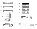
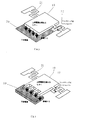
図2は、SOI(silicon on insulator)ウエハを使用して、シリコン窒化膜で形成する張力を持つトーションバーを製作するプロセスシーケンスを示したものである。
デバイス層シリコン:10μm、埋め込み酸化膜:2μm、ハンドリング層シリコン200μmのSOIウェハを1100℃で8時間ウェット酸化し、ウェハの表面に酸化膜を形成したものを素材として使用し、次の(a)から(j)の工程により製作が行われる。
成膜された酸化膜は平均1.7μmである。
(a)このSOIウェハの酸化膜をパターニングすることにより引張応力の入ったシリコン窒化膿を減圧CVDで500nm成膜する。
(b)裏面のハンドリング層シリコンを埋め込み酸化膜までKOHでエッチングして、表面の窒化膜に電極用コンタクトホールをエッチングする。
これは、トーションバーが窒化膜で絶縁物であるため、電気的な接続が取れないのに対して、後から成膜するAu/Cr膜を介した接続を可能とするためである。
(c)その後トーションバー付近のシリコン窒化膜を200nmエッチングを施しレジストを剥離する。
FIG. 2 shows a process sequence for manufacturing a torsion bar having a tension formed by a silicon nitride film using an SOI (silicon on insulator) wafer.
Device layer silicon: 10 μm, buried oxide film: 2 μm, handling layer silicon 200 μm SOI wafer is wet-oxidized at 1100 ° C. for 8 hours, and an oxide film is formed on the wafer surface, and the following (a) To (j).
The average oxide film formed is 1.7 μm.
(A) By patterning the oxide film of this SOI wafer, silicon nitride pus containing tensile stress is formed to a thickness of 500 nm by low pressure CVD.
(B) The handling layer silicon on the back surface is etched up to the buried oxide film with KOH, and the electrode contact hole is etched in the nitride film on the front surface.
This is because, since the torsion bar is a nitride film and is an insulator, it cannot be electrically connected, but can be connected via an Au / Cr film to be formed later.
(C) Thereafter, the silicon nitride film in the vicinity of the torsion bar is etched by 200 nm to remove the resist.
(d)KOHエッチングにより形成されたキヤビティーの側壁がミラー下部、櫛歯部分に陰を作るような角度から裏面にAu/Crを蒸着する。
(e)Au/Crをマスクとし緩衝フッ酸により2μmのSiO2を1μmに薄くする。
これは、後に述ペるように犠牲層エッチングを行う際に、ミラー部が先にリリースされることを狙ったものである。
(g)その後、Au/Crをエッチングにより除去し、櫛歯および全体の形状を決めるレイヤのパターニングを行う。
(h)ICP-RIEでシリコン窒化膜をエッチングしトーションバー付近のシリコンのみを露出させる。この時点では、櫛歯付近のシリコン窒化膜は厚さ200nm弱残っている。その後、ICP-RIEによりSF6ガスのみを用いた等方性の条件でトーションバー下部のシリコンがなくなるようにサイドエッチングを入れ、シリコン窒化膜のみの中空構造にする。これが、トーションバーとなる。
櫛歯付近にはシリコン窒化膜が残っているため、エッチングが行われず、トーションバー付近のみを等方性の条件でエッチングすることが可能となっている。
シリコンとシリコン窒化膜のエッチング選択比は140以上であり、シリコンとシリコン窒化膜を選択的にエッチングすることが可能であった。
(i)次に、残していた窒化膜を再びエッチングし櫛歯付近などのシリコン部分を露出させ、Deep RIE により垂直にエッチングし、櫛歯を形成する。
(j)電極用のAu/Crを斜めから蒸着させる。最後にフッ酸蒸気を用い、埋め込み酸化膜をドライエッチングしリリースとなる 。
上記の(e)の工程で埋め込み酸化膜に膜厚差を設けることにより、リリースの工程(j)において、埋め込み酸化膜の薄いミラー、櫛歯部分を早くリリースさせ、固定櫛歯が反ることからミラー部を切り離し、ミラーを安全にリリースさせることが出来る。
(D) Au / Cr is vapor-deposited on the back surface from such an angle that the side wall of the cavity formed by KOH etching shades the lower part of the mirror and the comb tooth part.
(E) Using Au / Cr as a mask, 2 μm of SiO 2 is thinned to 1 μm with buffered hydrofluoric acid.
This is intended to release the mirror portion first when performing sacrificial layer etching as described later.
(G) Thereafter, Au / Cr is removed by etching, and patterning of a layer that determines the comb teeth and the overall shape is performed.
(H) The silicon nitride film is etched by ICP-RIE to expose only silicon near the torsion bar. At this time, the silicon nitride film near the comb teeth remains with a thickness of less than 200 nm. Thereafter, side etching is performed by ICP-RIE so that silicon under the torsion bar disappears under isotropic conditions using only SF 6 gas, thereby forming a hollow structure of only a silicon nitride film. This becomes the torsion bar.
Since the silicon nitride film remains in the vicinity of the comb teeth, etching is not performed, and only the vicinity of the torsion bar can be etched under isotropic conditions.
The etching selectivity between silicon and silicon nitride film was 140 or more, and it was possible to selectively etch silicon and silicon nitride film.
(I) Next, the remaining nitride film is etched again to expose the silicon portion such as the vicinity of the comb teeth and etched vertically by Deep RIE to form comb teeth.
(J) Au / Cr for electrodes is deposited obliquely. Finally, hydrofluoric acid vapor is used to dry-etch the buried oxide film and release.
By providing a thickness difference in the buried oxide film in the above step (e), the thin mirror and comb teeth of the buried oxide film are released quickly in the release step (j), and the fixed comb teeth are warped. The mirror part can be separated from the mirror and the mirror can be released safely.
図3は、減圧CVD成膜によって得られたシリコン室化膜に生じる膜応力を成膜条件の変化とともに示したもので、縦軸に残留応力(Kgf/mm2)を、横軸にSiH2Cl2/NH3 比を示したものである。
図3に示すように、温度850℃で、SiH2Cl2ガス/NH3ガスの混合比を0.5にすると引っ張り応力60Kgf/mm2=600MPaが得られる。混合比を5.3にすると応力をほぼ0にすることもできる。従って、シリコン窒化膜を利用して張力の含まれたトーションバーも、張力0のトーションバーも製作することができる。
FIG. 3 shows the film stress generated in the silicon chamber film obtained by the low pressure CVD film formation along with the change of the film formation conditions. The vertical axis represents the residual stress (Kgf / mm 2 ), and the horizontal axis represents SiH 2. The Cl 2 / NH 3 ratio is shown.
As shown in FIG. 3, when the mixing ratio of SiH 2 Cl 2 gas / NH 3 gas is 0.5 at a temperature of 850 ° C., a tensile stress of 60 kgf / mm 2 = 600 MPa is obtained. When the mixing ratio is 5.3, the stress can be made almost zero. Therefore, a torsion bar including tension and a torsion bar having zero tension can be manufactured using the silicon nitride film.
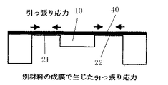
図4は、シリコン構造体により製作された張力持っていないトーションバーに張力を持たせる方法の実施例を説明した図である。
図4において、10はマイクロミラー、21,22はマイクロミラー10を支持するトーションバーである。40はトーションバー21,22の表面にスパッタ蒸着したクロム膜である。
スパッタ蒸着したクロム膜には強い引っ張り応力が含まれることが知られている。予め張力0のトーションバーを製作した場合、又は他の方法で製作したトーションバーには張力を持っていない場合には、図4に示すような電気的接続を得るために後で金属蒸着するクロム膜を利用することで引張応力を得ることができる。
膜応力にはよらずに、製作したシリコン構造体を変形することで、製作後に張力を加えることもできる。
FIG. 4 is a diagram for explaining an embodiment of a method for applying tension to a torsion bar having no tension manufactured by a silicon structure.
In FIG. 4, 10 is a micromirror, and 21 and 22 are torsion bars that support the
It is known that sputter-deposited chromium films contain strong tensile stress. If a torsion bar with zero tension is manufactured in advance, or if the torsion bar manufactured by another method has no tension, chromium is later deposited by metal to obtain an electrical connection as shown in FIG. Tensile stress can be obtained by using a film.
Tension can be applied after fabrication by deforming the fabricated silicon structure without depending on the film stress.
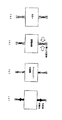
図5は、製作したシリコン構造体を変形することで、製作後に張力を加える方法の実施例を説明した図である。
図5において、10はマイクロミラー、21,22はマイクロミラー10を支持するトーションバーである。
図5の実施例では、(a)に示すように、トーションバー21,22をシリコンの2本の梁で製作しておき、(b)(c)に示すように、製作後に通電過熱によって熱的に変形・接触して一体化した後に、(d)に示すように、室温まで冷すことで、トーションバーに張力を生じさせることができる。トーションバーそのものでなくても、周辺構造を変形させて同等の効果を得ることが可能である。
FIG. 5 is a diagram for explaining an embodiment of a method for applying tension after fabrication by deforming a fabricated silicon structure.
In FIG. 5, 10 is a micromirror, and 21 and 22 are torsion bars that support the
In the embodiment of FIG. 5, the torsion bars 21 and 22 are made of two beams of silicon as shown in (a), and heat is generated by energization overheating after the production as shown in (b) and (c). After being deformed, contacted and integrated, as shown in (d), the torsion bar can be tensioned by cooling to room temperature. Even if it is not the torsion bar itself, it is possible to obtain the same effect by deforming the surrounding structure.
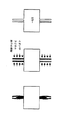
図6は製作したシリコン構造体にイオンやラジカルを照射することで、合力として張力を発生させる方法の実施例を説明した図である。
図6において、10はマイクロミラー、21,22はマイクロミラー10を支持するトーションバーである。
図6の実施例では、(a)に示すように、トーションバー21,22をシリコンの2本の梁で製作しておき、(b)に示すように、外側からイオンやラジカルを照射して、圧縮応力を発生させ、(c)に示すように、合力としてトーションバーに張力応力を生じさせることができる。
FIG. 6 is a diagram for explaining an embodiment of a method for generating tension as a resultant force by irradiating the manufactured silicon structure with ions or radicals.
In FIG. 6,
In the embodiment of FIG. 6, the torsion bars 21 and 22 are made of two silicon beams as shown in (a), and ions and radicals are irradiated from the outside as shown in (b). Then, compressive stress is generated, and as shown in (c), tensile stress can be generated in the torsion bar as a resultant force.
図7は、本発明のトーションバーを用いた静電駆動型マイクロミラーデバイスの駆動電圧一回転角度の関係を示す特性を示した図で、縦軸にミラー回転角Tilting Angleを、横軸に駆動電圧Driving Voltageを示したものである。
図7のデータは、繰り返し精度を評価するため、初めに計測した結果と、周波数2Hzで1時間(7200cycle)駆動した直後に計測したものを示す。
駆動電圧5Vで2.5°の回転角が得られた。その際には下に引き込まれたミラー変位は100nm以下であることが確認された。面内方向の回転は観察されなかった。
FIG. 7 is a graph showing characteristics indicating the relationship of one rotation angle of the driving voltage of the electrostatic drive type micromirror device using the torsion bar of the present invention. The voltage Driving Voltage is shown.
The data in FIG. 7 shows the results of the measurement at the beginning and the data measured immediately after driving for 1 hour (7200 cycles) at a frequency of 2 Hz in order to evaluate the repeatability.
A rotation angle of 2.5 ° was obtained at a driving voltage of 5V. At that time, it was confirmed that the mirror displacement drawn down was 100 nm or less. In-plane rotation was not observed.
本発明は MEMSを使用した各種の光学部品製造産業で利用可能である。 The present invention can be used in various optical component manufacturing industries using MEMS.
10・・・マイクロミラー,
21,22・・・マイクロミラー10を支持するトーションバー,
30・・・マイクロミラー10を駆動する駆動電極,
40・・・トーションバー21,22の表面にスパッタ蒸着したクロム膜,
10 ... Micromirror,
21, 22 ... Torsion bars that support the
30: Drive electrode for driving the
40 ... Chromium film sputter-deposited on the surface of the torsion bars 21,22,
Claims (6)
前記トーションバーに張力を持たせてミラーを支持させることにより、回転方向に柔らかく上下左右方向には剛性を高くして、安定にミラーの回転動作が得られるようにしたことを特徴とするトーションバーを用いた静電駆動型マイクロミラーデバイス。 In an electrostatically driven micromirror device using a torsion bar that is integrally formed with a micromirror and rotatably supports the micromirror,
The torsion bar is characterized in that the mirror is supported by applying tension to the torsion bar so that the mirror is soft in the rotational direction and rigid in the vertical and horizontal directions so that the mirror can be rotated stably. Electrostatic drive type micromirror device using
前記トーションバーに引っ張り応力を利用することで張力を持たせてミラーを支持させることにより、回転方向に柔らかく上下左右方向には剛性を高くして、安定にミラーの回転動作が得られるようにしたことを特徴とするトーションバーを用いた静電駆動型マイクロミラーデバイス。 In an electrostatically driven micromirror device using a torsion bar that is integrally formed with a micromirror and rotatably supports the micromirror,
By applying tensile force to the torsion bar to support the mirror, the mirror is supported in a soft manner in the rotational direction and increased in rigidity in the vertical and horizontal directions so that the mirror can be rotated stably. An electrostatically driven micromirror device using a torsion bar.
前記トーションバーに引っ張り応力を持つよう成膜条件を制御した薄膜を利用することで張力を持たせてミラーを支持させることにより、回転方向に柔らかく上下左右方向には剛性を高くして、安定にミラーの回転動作が得られるようにしたことを特徴とするトーションバーを用いた静電駆動型マイクロミラーデバイス。 In an electrostatically driven micromirror device using a torsion bar that is integrally formed with a micromirror and rotatably supports the micromirror,
By using a thin film whose film formation conditions are controlled so that the torsion bar has a tensile stress, the tension is applied to support the mirror, so that the rotation is soft and the rigidity is increased in the vertical and horizontal directions. An electrostatically driven micromirror device using a torsion bar, characterized in that the mirror can be rotated.
前記トーションバーに応力が加わっていない状態で微細加工を施した後、トーションバーの部分に張力を持った膜を蒸着することにより張力を持たせてミラーを支持させることにより、回転方向に柔らかく上下左右方向には剛性を高くして、安定にミラーの回転動作が得られるようにしたことを特徴とするトーションバーを用いた静電駆動型マイクロミラーデバイス。 In an electrostatically driven micromirror device using a torsion bar that is integrally formed with a micromirror and rotatably supports the micromirror,
After applying micro processing without applying stress to the torsion bar, depositing a film with tension on the portion of the torsion bar to give the tension and support the mirror so that it softly moves up and down in the rotation direction. An electrostatically driven micromirror device using a torsion bar characterized in that rigidity is increased in the left-right direction so that the mirror can be rotated stably.
前記トーションバーに応力が加わっていない状態で微細加工を施し、熱処理によってトーションバーを変形させ、変形後に室温でトーションバーに沿った張力を発生させることにより、張力を持たせてミラーを支持させることにより、回転方向に柔らかく上下左右方向には剛性を高くして、安定にミラーの回転動作が得られるようにしたことを特徴とするトーションバーを用いた静電駆動型マイクロミラーデバイス。 In an electrostatically driven micromirror device using a torsion bar that is integrally formed with a micromirror and rotatably supports the micromirror,
Applying fine processing to the torsion bar without applying stress, deforming the torsion bar by heat treatment, and generating tension along the torsion bar at room temperature after deformation, thereby supporting the mirror with tension. Thus, an electrostatically driven micromirror device using a torsion bar that is soft in the rotational direction and has high rigidity in the vertical and horizontal directions so that the mirror can be rotated stably.
前記トーションバーに応力が加わっていない状態で微細加工を施し、イオンやラジカルを照射することでトーションバーに応力を発生させ、合力としてトーションバーに沿った張力を発生させることにより、張力を持たせてミラーを支持させることにより、回転方向に柔らかく上下左右方向には剛性を高くして、安定にミラーの回転動作が得られるようにしたことを特徴とするトーションバーを用いた静電駆動型マイクロミラーデバイス。
In an electrostatically driven micromirror device using a torsion bar that is integrally formed with a micromirror and rotatably supports the micromirror,
The torsion bar is subjected to microfabrication in a state where no stress is applied, and ions and radicals are irradiated to generate stress in the torsion bar, thereby generating tension along the torsion bar as a resultant force. By supporting the mirror, the electrostatic drive type micro that uses the torsion bar is characterized in that it is soft in the rotation direction and has high rigidity in the vertical and horizontal directions so that the mirror can be rotated stably. Mirror device.
Priority Applications (1)
| Application Number | Priority Date | Filing Date | Title |
|---|---|---|---|
| JP2004140525A JP4446038B2 (en) | 2004-05-11 | 2004-05-11 | Electrostatically driven micromirror device using torsion bar |
Applications Claiming Priority (1)
| Application Number | Priority Date | Filing Date | Title |
|---|---|---|---|
| JP2004140525A JP4446038B2 (en) | 2004-05-11 | 2004-05-11 | Electrostatically driven micromirror device using torsion bar |
Publications (2)
| Publication Number | Publication Date |
|---|---|
| JP2005321663A true JP2005321663A (en) | 2005-11-17 |
| JP4446038B2 JP4446038B2 (en) | 2010-04-07 |
Family
ID=35468997
Family Applications (1)
| Application Number | Title | Priority Date | Filing Date |
|---|---|---|---|
| JP2004140525A Expired - Lifetime JP4446038B2 (en) | 2004-05-11 | 2004-05-11 | Electrostatically driven micromirror device using torsion bar |
Country Status (1)
| Country | Link |
|---|---|
| JP (1) | JP4446038B2 (en) |
Cited By (7)
| Publication number | Priority date | Publication date | Assignee | Title |
|---|---|---|---|---|
| JP2008055516A (en) * | 2006-08-29 | 2008-03-13 | Fujitsu Ltd | Micro oscillating device |
| JP2008292451A (en) * | 2007-01-19 | 2008-12-04 | Stmicroelectronics Srl | Oxygen absorber and deoxygenation container with excellent swelling resistance, peeling resistance and surface smoothness |
| US7564890B2 (en) | 2005-12-20 | 2009-07-21 | Denso Corporation | Laser equipment |
| JP2011521797A (en) * | 2008-05-29 | 2011-07-28 | フリースケール セミコンダクター インコーポレイテッド | Capacitive sensor with stress relief to compensate package stress |
| JP2012115981A (en) * | 2011-12-09 | 2012-06-21 | Fujitsu Ltd | Micro-oscillation element |
| US9834437B2 (en) | 2014-12-02 | 2017-12-05 | Csmc Technologies Fabi Co., Ltd. | Method for manufacturing MEMS torsional electrostatic actuator |
| EP3919436A1 (en) | 2020-06-03 | 2021-12-08 | Funai Electric Co., Ltd. | Vibrating element |
Families Citing this family (1)
| Publication number | Priority date | Publication date | Assignee | Title |
|---|---|---|---|---|
| CN110849507A (en) * | 2019-11-20 | 2020-02-28 | 清华大学 | Film stress detection structure in MEMS and preparation method thereof |
-
2004
- 2004-05-11 JP JP2004140525A patent/JP4446038B2/en not_active Expired - Lifetime
Cited By (10)
| Publication number | Priority date | Publication date | Assignee | Title |
|---|---|---|---|---|
| US7564890B2 (en) | 2005-12-20 | 2009-07-21 | Denso Corporation | Laser equipment |
| US7843987B2 (en) | 2005-12-20 | 2010-11-30 | Denso Corporation | Laser equipment |
| JP2008055516A (en) * | 2006-08-29 | 2008-03-13 | Fujitsu Ltd | Micro oscillating device |
| JP2008292451A (en) * | 2007-01-19 | 2008-12-04 | Stmicroelectronics Srl | Oxygen absorber and deoxygenation container with excellent swelling resistance, peeling resistance and surface smoothness |
| US8661900B2 (en) | 2007-01-19 | 2014-03-04 | Stmicroelectronics S.R.L. | Z-axis microelectromechanical device with improved stopper structure |
| JP2011521797A (en) * | 2008-05-29 | 2011-07-28 | フリースケール セミコンダクター インコーポレイテッド | Capacitive sensor with stress relief to compensate package stress |
| JP2012115981A (en) * | 2011-12-09 | 2012-06-21 | Fujitsu Ltd | Micro-oscillation element |
| US9834437B2 (en) | 2014-12-02 | 2017-12-05 | Csmc Technologies Fabi Co., Ltd. | Method for manufacturing MEMS torsional electrostatic actuator |
| EP3919436A1 (en) | 2020-06-03 | 2021-12-08 | Funai Electric Co., Ltd. | Vibrating element |
| US11921283B2 (en) | 2020-06-03 | 2024-03-05 | Funai Electric Co., Ltd. | Vibrating element |
Also Published As
| Publication number | Publication date |
|---|---|
| JP4446038B2 (en) | 2010-04-07 |
Similar Documents
| Publication | Publication Date | Title |
|---|---|---|
| JP3065611B1 (en) | Micromirror device and manufacturing method thereof | |
| JP5313666B2 (en) | MEMS device, light control method, and mirror formation method | |
| JP4401442B2 (en) | Manufacturing method for micromechanical devices | |
| JP4206102B2 (en) | Actuator with vertical comb electrode | |
| JP4385938B2 (en) | Actuator | |
| US20050099665A1 (en) | Frequency tunable resonant scanner | |
| US6679995B1 (en) | Method of micromechanical manufacturing of a semiconductor element, in particular an acceleration sensor | |
| JP2012528343A (en) | Micromachining type component and method of manufacturing the micromachining type component | |
| US6838304B2 (en) | MEMS element manufacturing method | |
| US7042613B2 (en) | Bouncing mode operated scanning micro-mirror | |
| JP4446038B2 (en) | Electrostatically driven micromirror device using torsion bar | |
| Chollet et al. | A (not so) short introduction to Micro Electro Mechanical Systems | |
| JP2016114798A (en) | Optical deflector and manufacturing method for optical deflector | |
| CN101279712B (en) | Method for generating a micromechanical structure | |
| Jeong et al. | A novel microfabrication of a self-aligned vertical comb drive on a single SOI wafer for optical MEMS applications | |
| JP7386625B2 (en) | Method for manufacturing an optical deflector and optical deflector | |
| JP2005506909A (en) | Reinforced surface micromachined structure and manufacturing method thereof | |
| US7261825B2 (en) | Method for the production of a micromechanical device, particularly a micromechanical oscillating mirror device | |
| TW200925104A (en) | MEMS scanning micromirror manufacturing method | |
| CN103018895A (en) | Simulation micro-mirror for surface micro-machining | |
| JP7105934B2 (en) | MEMS mirror device and its manufacturing method | |
| TWI249506B (en) | Optical micro-electromechanical device and its manufacturing method | |
| Sasaki et al. | Performance of tense thin-film torsion bar for large rotation and low-voltage driving of micromirror | |
| JP7073876B2 (en) | Semiconductor devices and their manufacturing methods | |
| JP2001001300A (en) | Fine beam structure and manufacturing method thereof |
Legal Events
| Date | Code | Title | Description |
|---|---|---|---|
| A621 | Written request for application examination |
Free format text: JAPANESE INTERMEDIATE CODE: A621 Effective date: 20070508 |
|
| A977 | Report on retrieval |
Free format text: JAPANESE INTERMEDIATE CODE: A971007 Effective date: 20090401 |
|
| A131 | Notification of reasons for refusal |
Free format text: JAPANESE INTERMEDIATE CODE: A131 Effective date: 20090811 |
|
| A521 | Request for written amendment filed |
Free format text: JAPANESE INTERMEDIATE CODE: A523 Effective date: 20090925 |
|
| A521 | Request for written amendment filed |
Free format text: JAPANESE INTERMEDIATE CODE: A523 Effective date: 20091001 |
|
| TRDD | Decision of grant or rejection written | ||
| A01 | Written decision to grant a patent or to grant a registration (utility model) |
Free format text: JAPANESE INTERMEDIATE CODE: A01 Effective date: 20091124 |
|
| A01 | Written decision to grant a patent or to grant a registration (utility model) |
Free format text: JAPANESE INTERMEDIATE CODE: A01 |
|
| A61 | First payment of annual fees (during grant procedure) |
Free format text: JAPANESE INTERMEDIATE CODE: A61 Effective date: 20091201 |
|
| R150 | Certificate of patent or registration of utility model |
Ref document number: 4446038 Country of ref document: JP Free format text: JAPANESE INTERMEDIATE CODE: R150 Free format text: JAPANESE INTERMEDIATE CODE: R150 |
|
| EXPY | Cancellation because of completion of term |