JP2005319528A - Method of polishing curved surface of workpiece - Google Patents
Method of polishing curved surface of workpiece Download PDFInfo
- Publication number
- JP2005319528A JP2005319528A JP2004138386A JP2004138386A JP2005319528A JP 2005319528 A JP2005319528 A JP 2005319528A JP 2004138386 A JP2004138386 A JP 2004138386A JP 2004138386 A JP2004138386 A JP 2004138386A JP 2005319528 A JP2005319528 A JP 2005319528A
- Authority
- JP
- Japan
- Prior art keywords
- polishing
- layer
- abrasive
- workpiece
- curved surface
- Prior art date
- Legal status (The legal status is an assumption and is not a legal conclusion. Google has not performed a legal analysis and makes no representation as to the accuracy of the status listed.)
- Pending
Links
Images


Classifications
-
- B—PERFORMING OPERATIONS; TRANSPORTING
- B24—GRINDING; POLISHING
- B24D—TOOLS FOR GRINDING, BUFFING OR SHARPENING
- B24D11/00—Constructional features of flexible abrasive materials; Special features in the manufacture of such materials
-
- B—PERFORMING OPERATIONS; TRANSPORTING
- B24—GRINDING; POLISHING
- B24B—MACHINES, DEVICES, OR PROCESSES FOR GRINDING OR POLISHING; DRESSING OR CONDITIONING OF ABRADING SURFACES; FEEDING OF GRINDING, POLISHING, OR LAPPING AGENTS
- B24B21/00—Machines or devices using grinding or polishing belts; Accessories therefor
- B24B21/004—Machines or devices using grinding or polishing belts; Accessories therefor using abrasive rolled strips
-
- B—PERFORMING OPERATIONS; TRANSPORTING
- B24—GRINDING; POLISHING
- B24B—MACHINES, DEVICES, OR PROCESSES FOR GRINDING OR POLISHING; DRESSING OR CONDITIONING OF ABRADING SURFACES; FEEDING OF GRINDING, POLISHING, OR LAPPING AGENTS
- B24B5/00—Machines or devices designed for grinding surfaces of revolution on work, including those which also grind adjacent plane surfaces; Accessories therefor
- B24B5/36—Single-purpose machines or devices
- B24B5/42—Single-purpose machines or devices for grinding crankshafts or crankpins
Landscapes
- Engineering & Computer Science (AREA)
- Mechanical Engineering (AREA)
- Polishing Bodies And Polishing Tools (AREA)
- Finish Polishing, Edge Sharpening, And Grinding By Specific Grinding Devices (AREA)
Abstract
Description
本発明は、工作物の曲面を研磨する方法に関し、特に円筒状工作物の外周面を研磨する方法に関する。 The present invention relates to a method for polishing a curved surface of a workpiece, and more particularly to a method for polishing an outer peripheral surface of a cylindrical workpiece.
工作物の凸面、凹面及び球面、円筒やくびれた円筒の外周面のような曲面は、工作物の曲面とシート状の研磨材料とを接触させ、この研磨材料に対して工作物を動かすことにより研磨される。ここでいう工作物には、例えば、ガラス、セラミック、金属等の硬質材料で構成された部材が含まれる。例えば、円筒状工作物の外周面は、シート状の研磨材料を円筒状工作物の外周面に押し当て、研削液を供給しながら円筒状工作物を回転させ、研磨材料を徐々に送って研磨することができる。精密な表面仕上げを行う場合、このような研磨方法は、例えば、スーパーフィニッシング装置(米国オハイオ州ヤングスタウンGEM社製GEM04150P型)やマイクロフィニッシャー装置(日本国富山県不二越本町不二越社製GBQ740/1500/1800型)を使用して、所望により横方向にオシレーションを行いながら実施される。 Curved surfaces such as the convex surface, concave surface and spherical surface of a workpiece, the outer surface of a cylinder or a constricted cylinder are brought into contact with the curved surface of the workpiece and a sheet-like abrasive material, and the workpiece is moved relative to this abrasive material. Polished. The workpiece here includes, for example, a member made of a hard material such as glass, ceramic, or metal. For example, the outer peripheral surface of a cylindrical workpiece is polished by pressing a sheet-like abrasive material against the outer peripheral surface of the cylindrical workpiece, rotating the cylindrical workpiece while supplying a grinding fluid, and gradually feeding the abrasive material. can do. In the case of performing a precise surface finish, such a polishing method is, for example, a superfinishing device (GEM04150P type manufactured by Youngstown GEM, Ohio, USA) or a microfinisher device (GBQ740 / 1500 / manufactured by Fujikoshi Honmachi, Toyama, Japan). 1800), and is optionally performed while oscillating in the lateral direction.
工作物の表面を微細に仕上げるためには、繰返し一定の表面粗さを作り出す必要がある。精密研磨は、局所的な深いスクラッチを研磨して浅く均一なスクラッチに置き換えていく作業である。近年では、例えば、エンジンのクランクシャフトやカムシャフト用の円筒形部品の外周面はRa0.05μm以下という特に微細な仕上げレベルが要求されている。 In order to finely finish the surface of a workpiece, it is necessary to repeatedly create a certain surface roughness. Precision polishing is an operation of polishing a local deep scratch and replacing it with a shallow uniform scratch. In recent years, for example, the outer peripheral surface of a cylindrical part for an engine crankshaft or camshaft is required to have a particularly fine finishing level of Ra 0.05 μm or less.
精密研磨を行う際には、研磨材料として、研磨粒子をフィルム基材表面に静電コーティングしたり、研磨粒子と樹脂結合剤を含むスラリーをフィルム基材表面に塗布乾燥して製造した研磨テープが一般に使用されている。しかし、微細な研磨粒子をコーティングしただけの研磨面は不規則な微細構造となっている。そのため、特に金属等を研磨した場合に目詰まりが起こりやすく、研磨力の低下が早い。それゆえ研磨を効果的に行うためには研磨テープの送り速度を上げて常に目詰まりしていない研磨面で研磨しなければならず、大量の研磨材料を必要とし、微細な研磨面に仕上げるまでに長時間を要する。 When carrying out precision polishing, an abrasive tape produced by electrostatically coating abrasive particles on the surface of the film substrate as a polishing material or applying and drying a slurry containing abrasive particles and a resin binder on the surface of the film substrate is used. Generally used. However, the polished surface simply coated with fine abrasive particles has an irregular microstructure. For this reason, clogging is likely to occur particularly when metal or the like is polished, and the polishing power is rapidly reduced. Therefore, in order to perform polishing effectively, it is necessary to increase the feed speed of the polishing tape and polish it on a polishing surface that is not clogged at all times, requiring a large amount of polishing material and finishing it to a fine polishing surface. Takes a long time.
特許文献1には基材の片面に研磨層を有する研磨テープにおいて、研磨層の表面全面に多数の正六角形が均等配置され、正六角形の周囲及び中心部に凹状部が構成されている研磨テープが記載されている。 Patent Document 1 discloses a polishing tape having a polishing layer on one side of a base material, in which a large number of regular hexagons are uniformly arranged on the entire surface of the polishing layer, and concave portions are formed around and at the center of the regular hexagon. Is described.
特許文献2には基材と基材上に設けられた研磨層とを有し、該研磨層が規則的に複数配置された正確な形状の畝を有する研磨材料が記載されている。この文献において開示された実使用方法は、光学研磨用ディスクに関するものである。 Patent Document 2 describes a polishing material having a base and a polishing layer provided on the base, and having a precisely shaped wrinkle in which a plurality of the polishing layers are regularly arranged. The actual use method disclosed in this document relates to an optical polishing disk.
特許文献3には研磨時間を短縮するために、粗さの異なるラッピングフィルムによる複数段の研磨工程を、最終研磨工程に向かうにつれて粗さの細かいラッピングフィルムを使用して行う円筒状工作物の外周面の研磨方法が記載されている。
本発明は、上記従来の問題を解決するものであり、その目的とするところは、ローディング耐性および耐久性に優れ、工作物の曲面を研磨した場合に、微細な仕上げを短時間で提供できる研磨方法を提供することにある。 The present invention solves the above-mentioned conventional problems, and its object is polishing that is excellent in loading resistance and durability, and can provide a fine finish in a short time when the curved surface of a workpiece is polished. To provide a method.
本発明は、
基材と、基材上に設けられた研磨粒子及び結合剤を含む研磨層とを、有し、
該基材が主表面、長手方向、及び該長手方向に平行な向かい合った側端を有し、
該研磨層が該主表面に接着された第1層と結合剤中に分散された研磨粒子を含む第2層とを有し、
該研磨層がプリズム形又はプリズム台形の複数の平行な列であり、
該平行な列が該長手方向に対して10〜80度の角度を形成している、
研磨材料を提供する工程;
工作物の曲面と該研磨材料とを接触させる工程;及び
該研磨材料に対して該工作物を動かすことにより該曲面を少なくとも部分的に研磨する工程;
を包含する、工作物の曲面を研磨する方法を提供するものであり、そのことにより上記目的が達成される。
The present invention
A substrate and a polishing layer comprising abrasive particles and a binder provided on the substrate,
The substrate has a major surface, a longitudinal direction, and opposite side edges parallel to the longitudinal direction;
The abrasive layer has a first layer adhered to the main surface and a second layer comprising abrasive particles dispersed in a binder;
The polishing layer is a plurality of parallel rows of prismatic or prismatic trapezoids;
The parallel rows form an angle of 10 to 80 degrees with respect to the longitudinal direction;
Providing an abrasive material;
Contacting a curved surface of a workpiece with the abrasive material; and at least partially polishing the curved surface by moving the workpiece relative to the abrasive material;
The method for polishing a curved surface of a workpiece including the above-mentioned object is achieved.
本発明で用いる研磨材料は研磨層として、複数の畝の平行な列を有している。この畝の列は研磨材料の長手方向に対して角度を有している。また、畝の頂上の形状は基材表面に平行な面又は線であり、研磨粒子の被研磨面への当りが均一で、仕上げが極めて均一かつ精密である。 The polishing material used in the present invention has a plurality of parallel rows of ridges as a polishing layer. This row of ridges is angled with respect to the longitudinal direction of the abrasive material. Further, the shape of the top of the ridge is a plane or line parallel to the surface of the substrate, the contact of the abrasive particles with the surface to be polished is uniform, and the finish is extremely uniform and precise.
図1は本発明の一実施態様である研磨層が畝状構造を有する研磨材料の断面斜視図である。研磨材料100は、基材101と基材の表面上に設けられた研磨層102とを有する研磨材料である。
FIG. 1 is a cross-sectional perspective view of an abrasive material in which an abrasive layer according to an embodiment of the present invention has a bowl-like structure. The
本発明の基材に好ましい材料には、ポリマーフィルム、紙、布、金属フィルム、バルカンファイバー、不織基材、これらの組み合わせおよびこれらの処理品が含まれる。円筒状工作物の外周面を研磨する場合は、基材は柔軟性の材料であることが好ましい。また、基材は紫外線照射に対して透明であることが好ましい。製造工程において便利だからである。 Preferred materials for the substrate of the present invention include polymer films, paper, fabrics, metal films, vulcanized fibers, non-woven substrates, combinations thereof and processed products thereof. When polishing the outer peripheral surface of a cylindrical workpiece, the substrate is preferably a flexible material. Moreover, it is preferable that a base material is transparent with respect to ultraviolet irradiation. This is because it is convenient in the manufacturing process.
例えば、基材はポリエステルフィルムのようなポリマーフィルムであってよい。また、ポリマーフィルムは、研磨層の基材に対する接着を促進するためにポリエチレンアクリル酸のような材料で下塗りしてもよい。 For example, the substrate may be a polymer film such as a polyester film. The polymer film may also be primed with a material such as polyethylene acrylic acid to promote adhesion of the polishing layer to the substrate.
研磨層102は結合剤のマトリックスとその中に分散させた研磨粒子103とを含む。研磨層は、未硬化または未ゲル化状態の結合剤中に分散された複数の研磨粒子を含有するスラリーから形成される。硬化またはゲル化において、研磨層は固形化、すなわち予め定められた形状および予め定められた構造に固定される。
The
研磨粒子の寸法は最終仕上げ研磨では、0.01〜1μm、好ましくは0.01〜0.5μmさらに好ましくは0.01〜0.1μm、粗研磨には、0.5〜20μm、好ましくは0.5〜10μmである。本発明に適する研磨粒子の例には、ダイヤモンド、立方晶窒化ボロン、酸化セリウム、溶融酸化アルミニウム、熱処理酸化アルミニウム、ゾルゲル酸化アルミニウム、シリコンカーバイド、酸化クロム、シリカ、ジルコニア、アルミナジルコニア、酸化鉄、ガーネット、およびこれらの混合物が含まれる。特に好ましいものは、粗研磨には、ダイヤモンド、立方晶窒化ホウ素、酸化アルミニウム、シリコンカーバイド、仕上げ研磨にはシリカ、酸化アルミニウムである。 The size of the abrasive particles is 0.01 to 1 μm, preferably 0.01 to 0.5 μm, more preferably 0.01 to 0.1 μm in final finish polishing, and 0.5 to 20 μm, preferably 0 in rough polishing. 5 to 10 μm. Examples of abrasive particles suitable for the present invention include diamond, cubic boron nitride, cerium oxide, molten aluminum oxide, heat treated aluminum oxide, sol-gel aluminum oxide, silicon carbide, chromium oxide, silica, zirconia, alumina zirconia, iron oxide, garnet. , And mixtures thereof. Particularly preferable are diamond, cubic boron nitride, aluminum oxide and silicon carbide for rough polishing, and silica and aluminum oxide for final polishing.
結合剤は硬化またはゲル化することにより研磨層を形成する。本発明に好ましい結合剤の例には、フェノール樹脂、レゾール−フェノール樹脂、アミノプラスト樹脂、ウレタン樹脂、エポキシ樹脂、アクリレート樹脂、ポリエステル樹脂、ビニル樹脂、メラミン樹脂、アクリレート化イソシアヌレート樹脂、尿素-ホルムアルデヒド樹脂、イソシアヌレート樹脂、アクリレート化ウレタン樹脂、アクリレート化エポキシ樹脂およびこれらの混合物が含まれる。特に好ましいものは、フェノール樹脂、有機溶剤を含む高分子レゾール−フェノール樹脂である。 The binder forms a polishing layer by curing or gelation. Examples of preferred binders for the present invention include phenolic resins, resol-phenolic resins, aminoplast resins, urethane resins, epoxy resins, acrylate resins, polyester resins, vinyl resins, melamine resins, acrylated isocyanurate resins, urea-formaldehyde. Resins, isocyanurate resins, acrylated urethane resins, acrylated epoxy resins, and mixtures thereof are included. Particularly preferred are a high molecular resol-phenol resin containing a phenol resin and an organic solvent.
結合剤は照射硬化性であってもよい。照射硬化性結合剤は照射エネルギーにより少なくとも部分的に硬化されるか、または少なくとも部分的に重合されうるいずれかの結合剤である。用いられる結合剤に依存して、熱、赤外線、電子線、紫外線照射または可視光照射のようなエネルギー源が用いられる。 The binder may be radiation curable. A radiation curable binder is any binder that can be at least partially cured or at least partially polymerized by irradiation energy. Depending on the binder used, energy sources such as heat, infrared, electron beam, ultraviolet irradiation or visible light irradiation are used.
典型的には、これらの結合剤はフリーラジカル機構により重合される。好ましくは、これらは、アクリレート化ウレタン、アクリレート化エポキシ、α,β-不飽和カルボニル基を有するアミノプラスト誘導体、エチレン性不飽和化合物、少なくとも1個のアクリレート基を有するイソシアヌレート誘導体、少なくとも1個のアクリレート基を有するイソシアネート、およびこれらの混合物からなる群から選択される。 Typically, these binders are polymerized by a free radical mechanism. Preferably, these are acrylated urethanes, acrylated epoxies, aminoplast derivatives having an α, β-unsaturated carbonyl group, ethylenically unsaturated compounds, isocyanurate derivatives having at least one acrylate group, at least one It is selected from the group consisting of isocyanates having acrylate groups and mixtures thereof.
結合剤が紫外線照射により硬化される場合は、フリーラジカル重合を開始させるために光開始剤を必要とする。この目的に好ましい光開始剤の例には、有機パーオキシド、アゾ化合物、キノン、ベンゾフェノン、ニトロソ化合物、アクリルハライド、ヒドラゾン、メルカプト化合物、ピリリウム化合物、トリアクリルイミダゾール、ビスイミダゾール、クロロアルキルトリアジン、ベンゾインエーテル、ベンジルケタール、チオキサントンおよびアセトフェノン誘導体が含まれる。好ましい光開始剤は2,2−ジメトキシ−1,2−ジフェニル−1−エタノンである。 When the binder is cured by UV irradiation, a photoinitiator is required to initiate free radical polymerization. Examples of preferred photoinitiators for this purpose include organic peroxides, azo compounds, quinones, benzophenones, nitroso compounds, acrylic halides, hydrazones, mercapto compounds, pyrylium compounds, triacrylimidazoles, bisimidazoles, chloroalkyltriazines, benzoin ethers, Benzyl ketal, thioxanthone and acetophenone derivatives are included. A preferred photoinitiator is 2,2-dimethoxy-1,2-diphenyl-1-ethanone.
結合剤が可視照射で硬化される場合は、光開始剤はフリーラジカル重合を開始させることが必要とされる。この目的のために好ましい光開始剤の例は、ここに参照として挙げる米国特許第4,735,632号、第3欄、第25行から第4欄第10行、第5欄第1〜7行、第6欄第1〜35行に記載されている。 If the binder is cured with visible radiation, the photoinitiator is required to initiate free radical polymerization. Examples of preferred photoinitiators for this purpose are U.S. Pat. No. 4,735,632, column 3, lines 25 to 4, line 10, lines 5-7, which are hereby incorporated by reference. Line, column 6, lines 1-35.
研磨粒子の結合剤に対する重量比は、一般に、1部の結合剤に対して約1.5部〜10部の研磨粒子、好ましくは1部の結合剤に対して約2〜7部の研磨粒子の範囲である。この割合は研磨粒子のサイズおよび用いる結合剤の種類や研磨材料の用途に依存して変化する。 The weight ratio of abrasive particles to binder is generally about 1.5 parts to 10 parts abrasive particles per part binder, preferably about 2 to 7 parts abrasive particles per part binder. Range. This ratio varies depending on the size of the abrasive particles, the type of binder used and the application of the abrasive material.
エンジンのクランクシャフトやカムシャフト用の円筒形部品のような硬質材料を滑らかかつ精密に研磨する場合に、研磨層中に含まれる研磨粒子の濃度の好ましい範囲は以下の通りである。研磨粒子がシリコンカーバイドの場合は43〜90重量%、アルミナ・シリカ等の球状研磨粒子の場合は70〜90重量%、アルミナの場合は37〜90重量%、そしてダイヤモンドの場合は39〜90重量%。 When a hard material such as an engine crankshaft or a cylindrical part for a camshaft is polished smoothly and precisely, the preferred range of the concentration of abrasive particles contained in the polishing layer is as follows. 43 to 90% by weight when the abrasive particles are silicon carbide, 70 to 90% by weight for spherical abrasive particles such as alumina and silica, 37 to 90% by weight for alumina, and 39 to 90% for diamond. %.
研磨層は研磨粒子および結合剤以外の材料を含んでよい。例えば、カップリング剤、湿潤剤、染料、顔料、可塑剤、フィラー、剥離剤、研磨補助剤およびこれらの混合物のような通常の添加剤である。 The abrasive layer may contain materials other than abrasive particles and a binder. For example, conventional additives such as coupling agents, wetting agents, dyes, pigments, plasticizers, fillers, release agents, polishing aids and mixtures thereof.
研磨層はカップリング剤を含むことができる。カップリング剤を添加することにより、研磨層を形成するために用いるスラリーの被覆粘度を著しく低下させうる。本発明に好ましいこのようなカップリング剤の例には、有機シラン、ジルコアルミネートおよびチタネートが含まれる。カップリング剤の量は、一般に、研磨層の全重量に対して5重量%未満、好ましくは1重量%未満である。 The polishing layer can contain a coupling agent. By adding a coupling agent, the coating viscosity of the slurry used to form the polishing layer can be significantly reduced. Examples of such coupling agents preferred for the present invention include organosilanes, zircoaluminates and titanates. The amount of coupling agent is generally less than 5% by weight, preferably less than 1% by weight, based on the total weight of the polishing layer.
研磨層102は、平行に配置された複数の畝104の列を有する。この畝104は三角柱を横向きにしたプリズム形状である。畝104の頂角βは通常30〜150゜、好ましくは45〜140゜とされる。畝の長手方向と垂直な面で切った断面は二等辺三角形でなくてもよい。畝の上記断面が二等辺三角形でない場合は、畝は急斜面と緩斜面とを有することになる。
The
畝104の頂上のリッジは研磨材料のほぼ全域に亘って基材表面と平行な平面上に存在している。そのことによって研磨粒子の被研磨面への当りが均一化し、仕上げが極めて均一かつ精密となる。図1中符号hは基材表面からの畝の高さを示す。hは通常2〜600μm、好ましくは4〜300μmとされる。頂上の線の高さのばらつきは畝104の高さの20%以内が好ましく、10%以内がより好ましい。
The top ridge of the
畝104は結合剤で成る麓部の第1層106、および研磨粒子を含む結合剤でなる頂上部の第2層を有する二層構造にすることが好ましい。畝104をこのような二層構造にすることで、比較的高価な研磨粒子の量が節約できるので研磨材料が低コストで提供できる。また、第1層106の結合剤は基材に対する接着性能のみを考慮して設計できるので、基材への接着不良が生じ難くなる。図1中、符号sは畝の頂上部の高さを示す。sは、例えば、畝の高さhの5〜95%、好ましくは10〜90%とされる。
The
畝104において研磨機能を発揮するのはその第2層105である。研磨材料が研磨に供されている間、畝は第2層から磨耗し、未使用の研磨粒子が現れる。従って、研磨材料の切削性を高めるためには第2層中の研磨粒子の濃度をできるだけ高めることが好ましい。研磨材料の切削性が高まり、硬質材料の研磨用途に適するからである。第2層中の研磨粒子の濃度は臨界顔料体積濃度(CPVC)の少なくとも90%であることがより好ましい。
It is the
ここでいう臨界顔料体積濃度(CPVC)とは、顔料と結合剤とを混合するとき、顔料粒子間のすき間を結合剤がちょうど埋めるときの粒子の顔料体積濃度(PVC)で、これ以下であれば結合剤が液状であれば混合物は流動性を有し、これ以上では流動性を失うという臨界的濃度をいう。 The critical pigment volume concentration (CPVC) as used herein means the pigment volume concentration (PVC) of the particles when the binder just fills the gaps between the pigment particles when the pigment and the binder are mixed. For example, it means a critical concentration in which the mixture has fluidity if the binder is in liquid form, and loses fluidity above this.
第1層106、すなわち、基材に接着する研磨層の下部は、通常は研磨機能を発揮しない。研磨層がそこまで摩耗した場合は通常研磨材料が廃棄されるからである。研磨機能を発揮しない第1層106は研磨粒子を含む必要はない。
The
畝104をこのような二層構造にすることで、比較的高価な研磨粒子の量が節約できるので研磨材料が低コストで提供できる。また、第1層106の結合剤は基材に対する接着性能のみを考慮して設計できるので、基材への接着不良が生じ難くなる。
By making the
畝104は縞状に配置される。図1中、符号wは畝の短底辺の長さ(畝の幅)を示す。符号pは畝の頂上間距離即ち畝のピッチと同じ長さを示す。符号uは畝の長底辺間距離を示す。wは、例えば、2〜2000μm、好ましくは4〜1000μmとされる。pは、例えば、2〜4000μm、好ましくは4〜2000μmとされる。uは、例えば、0〜2000μm、好ましくは0〜1000μmとされる。
The
畝104の長さは研磨材料のほぼ全域に亘って伸長されてよい。又は、適当な長さで中断してもよい。畝104の底面はアスペクト比2以上であればよく、好ましくは5以上である。その端部は揃えても揃えなくてもよい。プリズム形状の畝の端部を下から鋭角を付けて切り、四方に斜面が出た寄せ棟形状としてもよい。図2はこの態様の畝の上面図である。
The length of the
図2中、符号lは畝の長底辺長さを示す。符号vは畝の鋭角を付けて切り取られた距離を示す。符号xは畝の短底辺間距離を示す。符号w、p、およびuの意義は図4と同様である。lは、例えば、5〜10000μm、好ましくは10〜5000μmとされる。vは、例えば、0〜2000μm、好ましくは1〜1000μmとされる。xは、例えば、0〜2000μm、好ましくは0〜1000μmとされる。wは、例えば、2〜2000μm、好ましくは4〜1000μmとされる。pは、例えば、2〜4000μm、好ましくは4〜2000μmとされる。uは、例えば、0〜2000μm、好ましくは0〜1000μmとされる。 In FIG. 2, the symbol l indicates the long bottom side length of the ridge. The symbol v indicates the distance cut off with an acute angle of the ridge. The symbol x indicates the distance between the short bottom sides of the ridges. Signs w, p, and u have the same meaning as in FIG. l is, for example, 5 to 10,000 μm, preferably 10 to 5000 μm. v is, for example, 0 to 2000 μm, preferably 1 to 1000 μm. x is, for example, 0 to 2000 μm, preferably 0 to 1000 μm. For example, w is 2 to 2000 μm, preferably 4 to 1000 μm. p is, for example, 2 to 4000 μm, preferably 4 to 2000 μm. u is, for example, 0 to 2000 μm, preferably 0 to 1000 μm.
また、他の態様では、畝は頂上が所定の高さカットされたプリズム台形であってもよい。その場合、畝の頂上は基材表面と平行な平面で構成され、この平面の実質的に全てが基材表面と平行な平面上に存在することが好ましい。そのことによって研磨粒子の被研磨面への当りが均一化し、仕上げが極めて均一かつ精密となる。畝の高さは頂上をカットする前の立体要素の高さhの5〜95%、好ましくは10〜90%とされる。 In another aspect, the ridge may be a prism trapezoid whose top is cut to a predetermined height. In that case, it is preferable that the top of the ridge is constituted by a plane parallel to the substrate surface, and substantially all of this plane exists on a plane parallel to the substrate surface. As a result, the contact of the abrasive particles with the surface to be polished becomes uniform, and the finish becomes extremely uniform and precise. The height of the ridge is 5 to 95%, preferably 10 to 90%, of the height h of the three-dimensional element before cutting the top.
本発明の研磨材料の研磨面は畝状構造を有するため研磨作用は異方性であり、研磨面に対して被研磨面を移動させる方向によって研磨性能も異なってくる。円筒状工作物の外周面、特にエンジンのクランクシャフトやカムシャフト用の円筒形部品のような硬質材料を滑らかかつ精密に研磨する場合には、被研磨面が進行する方向が畝の長手方向と垂直にならないようにすることが好ましい。 Since the polishing surface of the polishing material of the present invention has a bowl-like structure, the polishing action is anisotropic, and the polishing performance varies depending on the direction in which the surface to be polished is moved relative to the polishing surface. When grinding hard materials such as cylindrical parts for cylindrical workpieces, especially cylindrical parts for engine crankshafts and camshafts, smoothly and precisely, the direction of the surface to be polished is the longitudinal direction of the rod. It is preferable not to be vertical.
図3は本発明の研磨材料に好ましい畝状構造の配置の例を模式的に示す上面図である。図3中矢印Aは研磨工程において被研磨面が進行する方向と平行な方向を示している。この方向を研磨材料の長手方向と呼ぶ。長手方向と垂直な方向を研磨材料の横方向と呼ぶ。円筒状工作物を研磨する場合、横方向はその軸と平行になる。研磨材料300の畝304はその長手方向と研磨材料の長手方向とが角度αを形成するように配置されている。
FIG. 3 is a top view schematically showing an example of the arrangement of a saddle-like structure preferable for the polishing material of the present invention. An arrow A in FIG. 3 indicates a direction parallel to the direction in which the surface to be polished advances in the polishing process. This direction is called the longitudinal direction of the polishing material. The direction perpendicular to the longitudinal direction is called the lateral direction of the abrasive material. When polishing a cylindrical workpiece, the transverse direction is parallel to its axis. The
角度αは5〜85度、好ましくは15〜80度、より好ましくは30〜70度の範囲で適宜調節される。αが5度未満であると微細な仕上がりが得難くなり、85度を越えると目詰まりが起こり易くなる。 The angle α is appropriately adjusted in the range of 5 to 85 degrees, preferably 15 to 80 degrees, more preferably 30 to 70 degrees. When α is less than 5 degrees, it is difficult to obtain a fine finish, and when it exceeds 85 degrees, clogging is likely to occur.
畝の配置形式は縞状には限られず、例えば、図4aに示すような、互い違いに配置したものや、図4bに示すような、ジグザグに配置したものであってもよい。 The arrangement form of the ridges is not limited to a stripe shape, and may be, for example, a staggered arrangement as shown in FIG. 4a or a zigzag arrangement as shown in FIG. 4b.
本発明で用いる研磨材料は特許文献2第0057〜0069段落に記載された方法により製造することが好ましい。 The abrasive material used in the present invention is preferably produced by the method described in paragraphs 0057 to 0069 of Patent Document 2.
本発明の研磨方法によれば、円筒状工作物の外周面を好適に研磨することができる。例えば、上述の研磨材料をその縦方向が軸と垂直になるように円筒状工作物の外周面に押し当て、例えば、潤滑剤、冷却剤、またはこれらの組み合わせを含む研削液を供給しながら円筒状工作物を回転させ、要すれば研磨材料を被研磨面が進行する方向と逆方向又は順方向に徐々に送って、更に要すれば横方向のオシレーションを行いながら、研磨を行うのである。このような研磨方法は、通常スーパーフィニッシング装置やマイクロフィニッシャー装置を使用して行われる。 According to the polishing method of the present invention, the outer peripheral surface of a cylindrical workpiece can be suitably polished. For example, the above-mentioned abrasive material is pressed against the outer peripheral surface of a cylindrical workpiece so that its longitudinal direction is perpendicular to the axis, and for example, a cylinder is supplied while supplying a grinding fluid containing a lubricant, a coolant, or a combination thereof. The workpiece is rotated, and if necessary, the polishing material is gradually fed in the opposite or forward direction to the surface to be polished, and if necessary, the polishing is performed while performing lateral oscillation. . Such a polishing method is usually performed using a super finishing device or a micro finisher device.
図5はスーパーフィニッシング装置の構成を示す模式図である。研磨材料501は繰り出しロール502から繰り出され、接触ロール503を経て巻き取りロール504に巻き取られる。接触ロールはエアシリンダー505によって円筒状工作物506の外周面に押し当てられる。円筒状工作物を矢印方向に回転させ、研磨材料を、被研磨面が進行する方向と逆方向に送りながら研磨が行われる。
FIG. 5 is a schematic diagram showing the configuration of the superfinishing apparatus. The polishing
図6はマイクロフィニッシャー装置の構成を示す模式図である。長尺の研磨材料601、602は、ストーン604を介してシュー605により円筒状工作物603の外周面に密着させ、押し付けられる。そして円筒状工作物を矢印方向に回転させ、研磨材料を、被研磨面が進行する方向と逆方向に送りながら研磨が行われる。
FIG. 6 is a schematic diagram showing the configuration of the microfinisher apparatus. The long
以下の実施例により本発明をさらに具体的に説明するが、本発明はこれらに限定されない。実施例中、成分の量を示す数値は特に断らない限り重量部を意味している。 The following examples further illustrate the present invention, but the present invention is not limited thereto. In the examples, numerical values indicating the amounts of the components mean parts by weight unless otherwise specified.
実施例1及び2
急斜面と緩斜面とを有するプリズム台形の畝を反転させた凹部を有するポリプロピレン製鋳型シートを準備した。鋳型シートに表1に示す組成の研磨材塗布液をナイフコーターにより塗布し、50℃で5分間乾燥させた。この上に表2に示すラミネート用結合剤を塗布し、帝人デュポンフィルム(日本国東京都千代田区)製の厚さ75μmのHPE易接着処理ポリエステルフィルムを重ね、ロールで圧力をかけてラミネートした。ポリエステルフィルムの側から紫外線を照射し、ラミネート用結合剤を硬化させた。次いで、90℃で20時間加熱して研磨材塗布液の結合剤を硬化させた。
Examples 1 and 2
A polypropylene mold sheet having a concave portion obtained by inverting a prism trapezoidal ridge having a steep slope and a gentle slope was prepared. An abrasive coating solution having the composition shown in Table 1 was applied to the mold sheet with a knife coater and dried at 50 ° C. for 5 minutes. On this, a binder for laminating shown in Table 2 was applied, and a 75 μm-thick HPE easy-adhesion-treated polyester film made by Teijin DuPont Film (Chiyoda-ku, Tokyo, Japan) was layered thereon and laminated by applying pressure with a roll. The binder for lamination was cured by irradiating ultraviolet rays from the polyester film side. Subsequently, the binder of the abrasive coating solution was cured by heating at 90 ° C. for 20 hours.
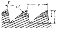
鋳型シートを除去し、更に110℃で24時間加熱し、その後室温まで冷却して研磨材料を得た。この研磨材料は、プリズム台形の畝が縞状に配置された研磨層を有している。図7は畝の長手方向と垂直な面で切ったこの研磨層の断面図である。各寸法を表3に示す。 The mold sheet was removed, and further heated at 110 ° C. for 24 hours, and then cooled to room temperature to obtain an abrasive material. This polishing material has a polishing layer in which prism trapezoidal ridges are arranged in stripes. FIG. 7 is a cross-sectional view of the polishing layer taken along a plane perpendicular to the longitudinal direction of the ridge. Each dimension is shown in Table 3.

得られた研磨材料を幅25mmの長尺シート状に成形した。その際に、畝の長手方向と研磨材料の長手方向との角度αが30度になるように、研磨材料の方向を調整した。得られた研磨材シートを巻き上げてロール状にした。 The obtained abrasive material was formed into a long sheet having a width of 25 mm. At that time, the direction of the abrasive material was adjusted so that the angle α between the longitudinal direction of the ridge and the longitudinal direction of the abrasive material was 30 degrees. The obtained abrasive sheet was rolled up into a roll.
実施例3〜6
図1に示す研磨層を反転させた形状の凹部を有するポリプロピレン製鋳型シート及び表4及び5に示す研磨材塗布液を用い、プリズム形状の各寸法を表6に示すように変更したこと以外は実施例1と同様にして研磨材料を得、幅25mmのロール状にした。
Examples 3-6
Except for using a polypropylene mold sheet having a concave portion having a shape obtained by inverting the polishing layer shown in FIG. 1 and the abrasive coating liquid shown in Tables 4 and 5, and changing the dimensions of the prism shape as shown in Table 6. A polishing material was obtained in the same manner as in Example 1 and formed into a roll having a width of 25 mm.
比較例1
スリーエム社(英国エイセルストーン)製研磨材料「マイクロフィニッシングフイルム 272L 20μm」を幅25mmの長尺シート状に成形し、巻き上げてロール状にした。
Comparative Example 1
An abrasive material “
比較例2
スリーエム社製研磨材料「マイクロフィニッシングフィルム 272L 30μm」を幅25mmの長尺シート状に成形し、巻き上げてロール状にした。
Comparative Example 2
A 3M abrasive material “Microfinishing Film 272L 30 μm” was formed into a long sheet having a width of 25 mm and rolled up into a roll.
比較例3
粒径5μmの酸化アルミニウムを研磨粒子として用い、研磨層がピラミッド形状のスリーエム社製研磨材料「トライザクトフィルム 272LA A5」を幅25mmの長尺シート状に成形し、巻き上げてロール状にした。
Comparative Example 3
Abrasive material “Trizact Film 272LA A5” made by 3M having a 5 μm particle size as abrasive particles and having a polishing layer having a pyramid shape was formed into a long sheet having a width of 25 mm and rolled up into a roll.
比較例4
住友スリーエム社製研磨材料「ラッピングフィルム 0.5μm 酸化アルミニウム タイプDHE」を幅25mmの長尺シート状に成形し、巻き上げてロール状にした。
Comparative Example 4
A polishing material “wrapping film 0.5 μm aluminum oxide type DHE” manufactured by Sumitomo 3M Co., Ltd. was formed into a long sheet having a width of 25 mm, and rolled up into a roll.
性能試験1
実施例1、実施例2、比較例1、比較例2で得た幅25mmのロール状研磨材料を日本国大阪府箕面市松田精機製スーパーフィニツシャーSP−100型に装着した。円筒状のワークピースを旋盤で回転し、研磨材料をワークピースの外周面に押し当て、研磨材料を徐々にに送って研磨した。研磨条件は表7のようであった。
Performance test 1
The roll-shaped abrasive material having a width of 25 mm obtained in Example 1, Example 2, Comparative Example 1, and Comparative Example 2 was mounted on a Super Finisher SP-100 type manufactured by Matsuda Seiki, Minoh City, Osaka, Japan. The cylindrical workpiece was rotated with a lathe, the abrasive material was pressed against the outer peripheral surface of the workpiece, and the abrasive material was gradually fed to be polished. The polishing conditions were as shown in Table 7.
研磨量(mg)を表8に、研磨後のワークピース表面の粗さ(Ra/μm)を触針式表面粗度計(株式会社ミツトヨ社(日本国神奈川県川崎)製「サーフテストSV−600」)で測定し表9に示した。表8より、実施例1及び実施例2の切削性が同じ研磨粒子粒径の比較例1、比較例2より優れていて、粗い番手の比較例3との中間であり、特に研磨材の送り速度の遅い領域で比較例に比べて切削性が高く、研磨材料の使用量を少なくすることができることが示された。 The polishing amount (mg) is shown in Table 8, and the roughness (Ra / μm) of the workpiece surface after polishing is measured by “Surf Test SV-” manufactured by Mitutoyo Co., Ltd. (Kawasaki, Kanagawa, Japan). 600 ”) and the results are shown in Table 9. From Table 8, the machinability of Example 1 and Example 2 is superior to that of Comparative Example 1 and Comparative Example 2 having the same abrasive particle diameter, and is intermediate between that of Comparative Example 3 with a coarse count, and in particular, the abrasive feed It was shown that the machinability is higher in the low speed region than in the comparative example, and the amount of abrasive material used can be reduced.
SH:研磨材進行方向が畝の急斜面側
MR4.0:研磨粒子/樹脂比=4.0
MR2.8:研磨粒子/樹脂比=2.8
SH: Steep slope side of abrasive material traveling direction
MR4.0: Abrasive particle / resin ratio = 4.0
MR2.8: Abrasive particle / resin ratio = 2.8
SH:研磨材進行方向が畝の急斜面側
MR4.0:研磨粒子/樹脂比=4.0
MR2.8:研磨粒子/樹脂比=2.8
SH: Abrasive direction of steep slope side
MR4.0: Abrasive particle / resin ratio = 4.0
MR2.8: Abrasive particle / resin ratio = 2.8
性能試験2
FC材(JIS G 5502 回転楕円体グラファイトキャスト鉄 FCD700−2)製の円筒形ワークピースをスリーエム社製研磨材料「マイクロフィニツシングフィルム 372L 9μm」を用いて研磨して外周面の表面粗度をRa=0.040〜0.45μmとした。実施例3、実施例4、実施例5、実施例6及び比較例3で得た幅25mmのロール状研磨材料を松田精機(日本国大阪府箕面市)製スーパーフィニツシャーに装着した。上記のワークピースを旋盤で回転し、研磨材料をワークピースの外周面に押し当て、研磨材料を徐々に送って研磨した。研磨条件は表10のようであった。
Performance test 2
A cylindrical workpiece made of FC material (JIS G5502 spheroidal graphite cast iron FCD700-2) is polished with 3M polishing material “Microfinishing Film 372L 9 μm” to reduce the surface roughness of the outer peripheral surface. Ra = 0.040-0.45 μm. The roll-shaped abrasive material having a width of 25 mm obtained in Example 3, Example 4, Example 5, Example 6 and Comparative Example 3 was mounted on a super finisher made by Matsuda Seiki (Mino City, Osaka, Japan). The workpiece was rotated on a lathe, the abrasive material was pressed against the outer peripheral surface of the workpiece, and the abrasive material was gradually fed to polish. The polishing conditions were as shown in Table 10.
研磨時間に対する研磨後のワークピース表面の粗さの変化を触針式表面粗度計で測定し、図8に示した。図8より、比較例3で前工程の研磨目を除去するのに60秒の研磨時間を必要とし、最終的に到達した仕上げ粗さはRa=0.033μmであったのに比べて、実施例3ではより短時間の研磨時間20〜40秒で仕上げ粗さRa=0.020〜0.021μm、実施例4では研磨時間40秒で仕上げ粗さRa=0.023μmの細かな仕上げを得ることができた。また、比較例3と同じ砥粒を使用した実施例5では研磨時間40〜60秒で仕上げ粗さRa=0.019〜0.020μmの細かな仕上げを得ることができ、本発明の効果が明確に現れた。
The change in roughness of the workpiece surface after polishing with respect to the polishing time was measured with a stylus type surface roughness meter, and is shown in FIG. As shown in FIG. 8, the polishing time of 60 seconds is required to remove the polishing marks of the previous process in Comparative Example 3, and the final roughness reached finally is Ra = 0.033 μm. In No. 3, it was possible to obtain a fine finish with a finishing roughness Ra = 0.020 to 0.021 μm in a
実施例6では研磨時間60〜80秒でその前工程の9μmの研磨目を除去することができ、一工程のみの研磨作業により仕上げ粗さRa=0.009μmの細かな仕上げを得ることができた。なお、以上の表面粗度測定は、カットオフ0.8mmの測定条件で行った。仕上げ粗さRa=O.01μm以下の表面粗度測定により適切なカットオフ0.08mmの測定条件で実施例6での仕上げ面を測定したところ、Ra=0.004μmの驚くほど細かな仕上げを得られた。 In Example 6, it was possible to remove the 9 μm polishing marks of the previous process in a polishing time of 60 to 80 seconds, and a fine finish with a finishing roughness Ra = 0.09 μm could be obtained by the polishing operation of only one process. . In addition, the above surface roughness measurement was performed on the measurement conditions of cutoff 0.8mm. When the finished surface in Example 6 was measured under the measurement condition of an appropriate cut-off of 0.08 mm by measuring the surface roughness with a finishing roughness Ra = 0.01 μm or less, a surprisingly fine finish with Ra = 0.004 μm was obtained. It was.
100...研磨材料、
101...基材、
102...研磨層、
103...研磨粒子、
104...畝。
100 ... Abrasive material,
101 ... Substrate,
102 ... polishing layer,
103 ... abrasive particles,
104 ... 畝.
Claims (3)
該基材が主表面、長手方向、及び該長手方向に平行な向かい合った側端を有し、
該研磨層が該主表面に接着された第1層と結合剤中に分散された研磨粒子を含む第2層とを有し、
該研磨層がプリズム形又はプリズム台形の複数の平行な列であり、
該平行な列が該長手方向に対して10〜80度の角度を形成している、
研磨材料を提供する工程;
工作物の曲面と該研磨材料とを接触させる工程;及び
該研磨材料に対して該工作物を動かすことにより該曲面を少なくとも部分的に研磨する工程;
を包含する、工作物の曲面を研磨する方法。 A substrate and a polishing layer comprising abrasive particles and a binder provided on the substrate,
The substrate has a major surface, a longitudinal direction, and opposite side edges parallel to the longitudinal direction;
The abrasive layer has a first layer adhered to the main surface and a second layer comprising abrasive particles dispersed in a binder;
The polishing layer is a plurality of parallel rows of prismatic or prismatic trapezoids;
The parallel rows form an angle of 10 to 80 degrees with respect to the longitudinal direction;
Providing an abrasive material;
Contacting a curved surface of a workpiece with the abrasive material; and at least partially polishing the curved surface by moving the workpiece relative to the abrasive material;
A method for polishing a curved surface of a workpiece.
Priority Applications (2)
| Application Number | Priority Date | Filing Date | Title |
|---|---|---|---|
| JP2004138386A JP2005319528A (en) | 2004-05-07 | 2004-05-07 | Method of polishing curved surface of workpiece |
| PCT/US2005/013329 WO2005113196A1 (en) | 2004-05-07 | 2005-04-19 | Abrading method of curvilinear surface of workpiece |
Applications Claiming Priority (1)
| Application Number | Priority Date | Filing Date | Title |
|---|---|---|---|
| JP2004138386A JP2005319528A (en) | 2004-05-07 | 2004-05-07 | Method of polishing curved surface of workpiece |
Publications (1)
| Publication Number | Publication Date |
|---|---|
| JP2005319528A true JP2005319528A (en) | 2005-11-17 |
Family
ID=34966405
Family Applications (1)
| Application Number | Title | Priority Date | Filing Date |
|---|---|---|---|
| JP2004138386A Pending JP2005319528A (en) | 2004-05-07 | 2004-05-07 | Method of polishing curved surface of workpiece |
Country Status (2)
| Country | Link |
|---|---|
| JP (1) | JP2005319528A (en) |
| WO (1) | WO2005113196A1 (en) |
Cited By (4)
| Publication number | Priority date | Publication date | Assignee | Title |
|---|---|---|---|---|
| WO2010011801A2 (en) | 2008-07-24 | 2010-01-28 | 3M Innovative Properties Company | Abrasive material product, its production method and use method |
| JP2012509195A (en) * | 2008-11-17 | 2012-04-19 | サンゴバン アブレシブ インコーポレーティド | Carboxylic ester color-stabilized phenolic resin bonded abrasive grain product and method for producing the same |
| JP2014120742A (en) * | 2012-12-19 | 2014-06-30 | Sumitomo Electric Ind Ltd | Powder compact, and surface processing method of powder compact |
| JP6996134B2 (en) | 2017-07-03 | 2022-01-17 | 株式会社Ihi | Processing equipment |
Families Citing this family (1)
| Publication number | Priority date | Publication date | Assignee | Title |
|---|---|---|---|---|
| FR2928291A3 (en) * | 2008-03-06 | 2009-09-11 | Renault Sas | Fixed abrasive cloth i.e. multilayer flexible ribbon, for covering e.g. crankshaft, of engine of motor vehicle, has abrasive surface whose non-abrasive part has lubricating portion made of spongy material soaked with lubricating liquid |
Citations (6)
| Publication number | Priority date | Publication date | Assignee | Title |
|---|---|---|---|---|
| JPS57126970U (en) * | 1981-02-03 | 1982-08-07 | ||
| JPS645775A (en) * | 1987-06-30 | 1989-01-10 | Tokin Corp | Surface polishing tape for magnetic recording medium |
| JPH03256676A (en) * | 1990-03-05 | 1991-11-15 | Romatetsuku Kk | Polishing cloth |
| JPH04228111A (en) * | 1990-07-02 | 1992-08-18 | Sony Corp | Cleaning calender roll device and cleaning tape used for the same |
| JPH11501439A (en) * | 1995-03-02 | 1999-02-02 | ミネソタ・マイニング・アンド・マニュファクチャリング・カンパニー | Method for texturing a support using a structured abrasive article |
| JP2001179640A (en) * | 1999-12-21 | 2001-07-03 | Three M Innovative Properties Co | Abrasive material with abrasive layer in solid structure |
-
2004
- 2004-05-07 JP JP2004138386A patent/JP2005319528A/en active Pending
-
2005
- 2005-04-19 WO PCT/US2005/013329 patent/WO2005113196A1/en active Application Filing
Patent Citations (6)
| Publication number | Priority date | Publication date | Assignee | Title |
|---|---|---|---|---|
| JPS57126970U (en) * | 1981-02-03 | 1982-08-07 | ||
| JPS645775A (en) * | 1987-06-30 | 1989-01-10 | Tokin Corp | Surface polishing tape for magnetic recording medium |
| JPH03256676A (en) * | 1990-03-05 | 1991-11-15 | Romatetsuku Kk | Polishing cloth |
| JPH04228111A (en) * | 1990-07-02 | 1992-08-18 | Sony Corp | Cleaning calender roll device and cleaning tape used for the same |
| JPH11501439A (en) * | 1995-03-02 | 1999-02-02 | ミネソタ・マイニング・アンド・マニュファクチャリング・カンパニー | Method for texturing a support using a structured abrasive article |
| JP2001179640A (en) * | 1999-12-21 | 2001-07-03 | Three M Innovative Properties Co | Abrasive material with abrasive layer in solid structure |
Cited By (6)
| Publication number | Priority date | Publication date | Assignee | Title |
|---|---|---|---|---|
| WO2010011801A2 (en) | 2008-07-24 | 2010-01-28 | 3M Innovative Properties Company | Abrasive material product, its production method and use method |
| JP2010046791A (en) * | 2008-07-24 | 2010-03-04 | Three M Innovative Properties Co | Abrasive material product, method of manufacturing the same, and use method |
| US9919406B2 (en) | 2008-07-24 | 2018-03-20 | 3M Innovative Properties Company | Abrasive material product, its production method and use method |
| JP2012509195A (en) * | 2008-11-17 | 2012-04-19 | サンゴバン アブレシブ インコーポレーティド | Carboxylic ester color-stabilized phenolic resin bonded abrasive grain product and method for producing the same |
| JP2014120742A (en) * | 2012-12-19 | 2014-06-30 | Sumitomo Electric Ind Ltd | Powder compact, and surface processing method of powder compact |
| JP6996134B2 (en) | 2017-07-03 | 2022-01-17 | 株式会社Ihi | Processing equipment |
Also Published As
| Publication number | Publication date |
|---|---|
| WO2005113196A1 (en) | 2005-12-01 |
Similar Documents
| Publication | Publication Date | Title |
|---|---|---|
| US5913716A (en) | Method of providing a smooth surface on a substrate | |
| JP3584062B2 (en) | Method for producing abrasive article | |
| JP2020075357A (en) | Polishing material having set with plurality of different polishing elements | |
| JP5555453B2 (en) | Abrasive product, method for producing and using the same | |
| JP3874790B2 (en) | Abrasive article, process for its production and its use for finishing | |
| US7267700B2 (en) | Structured abrasive with parabolic sides | |
| KR100384828B1 (en) | Abrasive article, a process of making same, and a method of using same to finish a workpiece surface | |
| JP3459246B2 (en) | Method of making coated abrasive article | |
| US20050064805A1 (en) | Structured abrasive article | |
| US20050060941A1 (en) | Abrasive article and methods of making the same | |
| JP4519970B2 (en) | Polishing material in which the polishing layer has a three-dimensional structure | |
| JPH11510745A (en) | Polishing article and its manufacturing method | |
| JPH07186030A (en) | Polish finishing method of optical lens | |
| WO2000007774A1 (en) | Abrasive article with integrally molded front surface protrusions containing a grinding aid and methods of making and using | |
| JP2009512566A (en) | Abrasive article and method of correcting surface of workpiece | |
| JP2002522237A (en) | Abrasive article with embossed isolation layer and method of making and using same | |
| EP1102660B1 (en) | Abrasive article with separately formed front surface protrusions containing a grinding aid and methods of making | |
| WO2005113196A1 (en) | Abrading method of curvilinear surface of workpiece | |
| US20050060942A1 (en) | Structured abrasive article | |
| US20050060945A1 (en) | Method of making a coated abrasive | |
| US20050060944A1 (en) | Method of making a coated abrasive |
Legal Events
| Date | Code | Title | Description |
|---|---|---|---|
| A621 | Written request for application examination |
Free format text: JAPANESE INTERMEDIATE CODE: A621 Effective date: 20070427 |
|
| A131 | Notification of reasons for refusal |
Free format text: JAPANESE INTERMEDIATE CODE: A131 Effective date: 20100309 |
|
| A521 | Written amendment |
Free format text: JAPANESE INTERMEDIATE CODE: A523 Effective date: 20100608 |
|
| A02 | Decision of refusal |
Free format text: JAPANESE INTERMEDIATE CODE: A02 Effective date: 20100713 |