JP2005310942A - Aligner, exposure method, and device manufacturing method using it - Google Patents
Aligner, exposure method, and device manufacturing method using it Download PDFInfo
- Publication number
- JP2005310942A JP2005310942A JP2004123870A JP2004123870A JP2005310942A JP 2005310942 A JP2005310942 A JP 2005310942A JP 2004123870 A JP2004123870 A JP 2004123870A JP 2004123870 A JP2004123870 A JP 2004123870A JP 2005310942 A JP2005310942 A JP 2005310942A
- Authority
- JP
- Japan
- Prior art keywords
- exposure apparatus
- optical system
- projection exposure
- projection
- light
- Prior art date
- Legal status (The legal status is an assumption and is not a legal conclusion. Google has not performed a legal analysis and makes no representation as to the accuracy of the status listed.)
- Abandoned
Links
Images


Classifications
-
- G—PHYSICS
- G03—PHOTOGRAPHY; CINEMATOGRAPHY; ANALOGOUS TECHNIQUES USING WAVES OTHER THAN OPTICAL WAVES; ELECTROGRAPHY; HOLOGRAPHY
- G03F—PHOTOMECHANICAL PRODUCTION OF TEXTURED OR PATTERNED SURFACES, e.g. FOR PRINTING, FOR PROCESSING OF SEMICONDUCTOR DEVICES; MATERIALS THEREFOR; ORIGINALS THEREFOR; APPARATUS SPECIALLY ADAPTED THEREFOR
- G03F7/00—Photomechanical, e.g. photolithographic, production of textured or patterned surfaces, e.g. printing surfaces; Materials therefor, e.g. comprising photoresists; Apparatus specially adapted therefor
- G03F7/70—Microphotolithographic exposure; Apparatus therefor
- G03F7/708—Construction of apparatus, e.g. environment aspects, hygiene aspects or materials
- G03F7/7095—Materials, e.g. materials for housing, stage or other support having particular properties, e.g. weight, strength, conductivity, thermal expansion coefficient
- G03F7/70958—Optical materials or coatings, e.g. with particular transmittance, reflectance or anti-reflection properties
-
- G—PHYSICS
- G03—PHOTOGRAPHY; CINEMATOGRAPHY; ANALOGOUS TECHNIQUES USING WAVES OTHER THAN OPTICAL WAVES; ELECTROGRAPHY; HOLOGRAPHY
- G03F—PHOTOMECHANICAL PRODUCTION OF TEXTURED OR PATTERNED SURFACES, e.g. FOR PRINTING, FOR PROCESSING OF SEMICONDUCTOR DEVICES; MATERIALS THEREFOR; ORIGINALS THEREFOR; APPARATUS SPECIALLY ADAPTED THEREFOR
- G03F7/00—Photomechanical, e.g. photolithographic, production of textured or patterned surfaces, e.g. printing surfaces; Materials therefor, e.g. comprising photoresists; Apparatus specially adapted therefor
- G03F7/70—Microphotolithographic exposure; Apparatus therefor
- G03F7/70058—Mask illumination systems
- G03F7/70075—Homogenization of illumination intensity in the mask plane by using an integrator, e.g. fly's eye lens, facet mirror or glass rod, by using a diffusing optical element or by beam deflection
Landscapes
- Physics & Mathematics (AREA)
- General Physics & Mathematics (AREA)
- Health & Medical Sciences (AREA)
- Engineering & Computer Science (AREA)
- Environmental & Geological Engineering (AREA)
- Epidemiology (AREA)
- Public Health (AREA)
- Exposure And Positioning Against Photoresist Photosensitive Materials (AREA)
- Microscoopes, Condenser (AREA)
- Exposure Of Semiconductors, Excluding Electron Or Ion Beam Exposure (AREA)
Abstract
Description
本発明は例えば半導体素子、液晶素子、薄膜磁気ヘッド等の各種デバイスを製造するためのリソグラフィ工程でフォトマスクやレチクル等の原板(本出願ではこれらの用語を交換可能に使用する)上の回路パターンを感光剤を塗布したウェハ等の基板上に投影転写するための露光装置、この装置を用いた露光方法、及びデバイスを製造する際に好適なものである。 The present invention relates to a circuit pattern on an original plate such as a photomask or a reticle (in this application, these terms are used interchangeably) in a lithography process for manufacturing various devices such as semiconductor elements, liquid crystal elements, and thin film magnetic heads. Is suitable for manufacturing an exposure apparatus for projecting onto a substrate such as a wafer coated with a photosensitive agent, an exposure method using the apparatus, and a device.
フォトリソグラフィ技術を用いてデバイスを製造する際に、レチクルに描画されたパターンを投影光学系によって基板(以後ウェハと呼ぶ)に投影してパターンを転写する投影露光装置が従来から使用されている。 2. Description of the Related Art When a device is manufactured using a photolithographic technique, a projection exposure apparatus that projects a pattern drawn on a reticle onto a substrate (hereinafter referred to as a wafer) by a projection optical system and transfers the pattern is conventionally used.
投影露光装置は一般に、光源から射出された光束を利用してレチクルを照明する照明光学系と、レチクルとウェハとの間に配置される投影光学系とを有する。照明光学系においては、典型的に、均一な照明領域を得るために光源からの光束をハエの目レンズなどのオプティカルインテグレータに導入し、オプティカルインテグレータ射出面を2次光源面としてコンデンサーレンズでレチクル面(もしくはそれと共役な面)をケーラー照明する。 In general, a projection exposure apparatus includes an illumination optical system that illuminates a reticle using a light beam emitted from a light source, and a projection optical system disposed between the reticle and a wafer. In an illumination optical system, in order to obtain a uniform illumination area, a light beam from a light source is typically introduced into an optical integrator such as a fly-eye lens, and the optical integrator exit surface is a secondary light source surface with a condenser lens as a reticle surface. (Or a conjugate plane) with Koehler illumination.
高品位な露光を行うためには、レチクルパターンに応じて最適な有効光源を形成する必要がある。有効光源とは、ウェハ面に入射する露光光束の角度分布を意味し、例えばハエの目レンズの射出面(即ち、2次光源面)近傍の強度分布を所望の形状(通常照明条件、輪帯照明条件、四重極照明条件、二重極照明条件)に調整することで実現している。 In order to perform high-quality exposure, it is necessary to form an optimum effective light source according to the reticle pattern. The effective light source means the angular distribution of the exposure light beam incident on the wafer surface. For example, the intensity distribution near the exit surface of the fly-eye lens (that is, the secondary light source surface) has a desired shape (normal illumination condition, annular zone). (Lighting conditions, quadrupole lighting conditions, dipole lighting conditions).
さて、投影露光装置の解像度Rは、光源の波長λ、投影光学系の開口数(NA)、現像プロセスなどによって定まる定数k1を用いて次式で与えられる。
R=k1(λ/NA)
The resolution R of the projection exposure apparatus is given by the following equation using a constant k 1 determined by the wavelength λ of the light source, the numerical aperture (NA) of the projection optical system, the development process, and the like.
R = k 1 (λ / NA)
近年のデバイスの高集積化に対応して、転写されるパターンの微細化、即ち、高解像度化が益々要求されている。高解像力を得るには、上式から波長λを小さくすること、及び、開口数NAを大きくすることが有効である。 In response to the recent high integration of devices, there is an increasing demand for miniaturization of transferred patterns, that is, higher resolution. In order to obtain high resolution, it is effective to reduce the wavelength λ and increase the numerical aperture NA from the above equation.
このため、露光装置に使用される露光光の波長はi線(365nm)からKrFエキシマレーザ(248nm)、ArFエキシマレーザ(193nm)へと移行してきている。一方、NAは0.70から0.75、0.85へと拡大の一途をたどってきおり、様々な露光装置が提案されている(例えば、特許文献1〜4参照。)。 For this reason, the wavelength of exposure light used in the exposure apparatus has shifted from i-line (365 nm) to KrF excimer laser (248 nm) and ArF excimer laser (193 nm). On the other hand, NA is steadily expanding from 0.70 to 0.75 and 0.85, and various exposure apparatuses have been proposed (for example, see Patent Documents 1 to 4).
図12にステップアンドスキャン方式の従来例を示す。1は光源で、例えばArFエキシマレーザ(193nm)などである。 FIG. 12 shows a conventional example of the step-and-scan method. Reference numeral 1 denotes a light source such as an ArF excimer laser (193 nm).
2は減光部材(ND)で、例えば透過率の異なる複数のNDが構成されている。そして、ウェハ14面上で最適な露光量となるようにND駆動手段21により組み合わされ、細かい減光率の調整が可能となっている。
Reference numeral 2 denotes a dimming member (ND), which includes, for example, a plurality of NDs having different transmittances. And it is combined by the ND driving means 21 so as to obtain an optimum exposure amount on the surface of the
3はビーム成形光学系で、複数の光学素子やズームレンズから構成されている。ビーム成形光学系3はレンズ系駆動手段22により駆動することで、後段のオプティカルインテグレータ4に入射する光束の強度分布及び角度分布を所望の分布にコントロールしている。 A beam shaping optical system 3 is composed of a plurality of optical elements and a zoom lens. The beam shaping optical system 3 is driven by the lens system driving means 22 to control the intensity distribution and angle distribution of the light beam incident on the optical integrator 4 at the subsequent stage to a desired distribution.
オプティカルインテグレータ4は複数の微小レンズを2次元的に配置した構成からなり、その射出面近傍に2次光源(有効光源)を形成している。 The optical integrator 4 has a configuration in which a plurality of microlenses are two-dimensionally arranged, and a secondary light source (effective light source) is formed in the vicinity of the exit surface thereof.
オプティカルインテグレータ4の射出面近傍には絞り5が配置され、必要に応じて絞り駆動機構23により絞りの大きさ及び形状を可変としている。
A
つまり、ビーム成形光学系3、オプティカルインテグレータ4、絞り5を使用することで、任意の有効光源形状(例えば、通常σや輪帯、四重極、二重極等)をレチクルパターンに応じて形成可能としている。
In other words, by using the beam shaping optical system 3, the optical integrator 4, and the
σはコヒーレンスファクタ−であり、「照明光のNA/投影光学系のNA」である。 σ is a coherence factor, which is “NA of illumination light / NA of projection optical system”.
6はコンデンサーレンズでオプティカルインテグレータ4の射出面近傍で形成された複数の2次光源から射出された光束を集光し、被照射面であるスキャンブレード7b面に重畳照射してその面を均一にしている。
A
18はハーフミラーで、オプティカルインテグレータ4から射出された光束の数%を反射し、積算露光量計測センサ17に導光している。17は、露光時の光量を常時検出するためのディテクタ(照度計、検出器)であり、ウェハ14面、レチクル10面と光学的に共役な位置に配置され、その出力に応じた信号を主制御装置30に送っている。
スキャンブレード7bは複数の可動な遮光板から成り、スキャンブレード駆動装置24により任意の開口形状が形成されるようにして、ウェハ14面上の露光範囲を規制している。
The scan blade 7b is composed of a plurality of movable light-shielding plates, and an arbitrary opening shape is formed by the scan
更にスキャンプレード7bは、レチクルステージ11、ウェハステージ15と同期して図中矢印方向に走査移動する。また、スキャンブレード7b近傍には、走査露光後の露光面における照度均一性の向上を図るため、可変スリット7aが配置されている。
Further, the scan plate 7b scans and moves in the direction of the arrow in the figure in synchronization with the
8a、8bは結像レンズで、スキャンブレード7bの開口形状を被照射面としてのレチクル10面上に転写し、レチクル面10上の必要な領域を均一に照明している。
Reference numerals 8a and 8b denote imaging lenses, which transfer the opening shape of the scan blade 7b onto the
ここで、レーザ1より後段からレチクル10より前段の光学系を総称して照明光学系と呼ぶこととする。
Here, the optical systems after the laser 1 and before the
レチクル10はレチクルステージ11によって保持され、レチクルステージ11はレチクルステージ駆動装置25によって制御されている。
The
12はレチクル10面上の回路パターンをウェハ14面上に縮小投影する投影光学系であり、複数のレンズ(12a〜12z・・・)から成る。13は投影光学系の瞳領域を制限するNA絞りで、NA絞り駆動装置26にてその開口寸法を変化させ、投影光学系12のNAを可変としている。14はレチクル10面上の回路パターンが投影転写されるウェハ(基板)であり、露光面に位置している。15はウェハ14を保持し光軸方向及び光軸と直交する平面に沿って2次元的に動くウェハステージである。ウェハステージ15はウェハステージ駆動装置27によって制御されている。
A projection
露光時には、レチクルステージ11とウェハステージ15が同期しながら、図中矢印の方向に走査露光を行う。尚、本発明における座標は、露光面にてウェハステージ15の走査方向と直交する方向をX方向、ウェハステージ15が走査する方向をY方向、投影光学系12の光軸方向をZ方向と定めることとする。
At the time of exposure, scanning exposure is performed in the direction of the arrow in the figure while the
16はウェハ14面上に入射する露光光の光量を検出するためのディテクタ(照度計、検出器)であり、ウェハ14面に受光部を一致させ照射領域内の照明光をウェハステージ15の駆動と共に移動して受光し、その出力に応じた信号を主制御装置30に送っている。30は主制御装置であり、各装置21〜27を制御している。
ステップアンドスキャン方式の露光方法は、レチクル10とウェハ14が図1の矢印方向に同期しながら走査露光を行う。投影光学系の縮小倍率が1/βの際には、ウェハステージ15の走査速度がV(mm/sec)のとき、レチクルステージ11の走査速度はβV(mm/sec)である。また、ウェハステージ15の走査方向とレチクルステージ11の走査方向は、互いに反対の方向である。
In the step-and-scan exposure method, the
ステップスキャン露光装置におけるインテグレータ照射範囲は図2に示すように、X方向に長く、Y方向(スキャン方向)に短い矩形分布となっている。そして、Y方向に走査露光することで、1ショット領域を確保している。 As shown in FIG. 2, the integrator irradiation range in the step scan exposure apparatus has a rectangular distribution that is long in the X direction and short in the Y direction (scan direction). Then, one shot area is secured by scanning exposure in the Y direction.
この矩形照明領域を実現するため、オプティカルインテグレータ4を構成する微小レンズのピッチや形状が決定されている。 In order to realize this rectangular illumination area, the pitch and shape of the microlenses constituting the optical integrator 4 are determined.
例えば、微小レンズの曲率をX方向とY方向に等しく設定する場合、矩形照明を実現するためには、微小レンズの開口形状を照明領域とほぼ相似の矩形となるように設定する。従って、微小レンズのピッチはX方向とY方向で異なる構成となる。 For example, when the curvature of the micro lens is set equal to the X direction and the Y direction, in order to realize rectangular illumination, the aperture shape of the micro lens is set to be a rectangle that is substantially similar to the illumination area. Accordingly, the pitch of the micro lenses is different in the X direction and the Y direction.
一方、微小レンズのピッチをX方向とY方向に等しく設定する場合には、矩形照明を実現するためにX方向とY方向の曲率を各々異なる値に設定する。
近年の露光装置は解像度の更なる向上を図るため、露光波長をi線(波長:365nm)からKrFエキシマレーザ(248nm)、ArFエキシマレーザ(193nm)と短くしてきている。波長193nmにおいて使用可能な硝材としては、高純度の石英(SiO2)と蛍石(CaF2)の2種類にほぼ限定されている。よって、露光装置を構成する光学素子は、石英と蛍石のそれぞれの特徴を考慮して最適に配置する必要がある。 In recent exposure apparatuses, in order to further improve the resolution, the exposure wavelength has been shortened from i-line (wavelength: 365 nm) to KrF excimer laser (248 nm) and ArF excimer laser (193 nm). The glass materials that can be used at a wavelength of 193 nm are almost limited to two types of high-purity quartz (SiO 2) and fluorite (CaF 2). Therefore, the optical elements constituting the exposure apparatus need to be optimally arranged in consideration of the characteristics of quartz and fluorite.
蛍石は波長193nmの光に対して約1.50の屈折率で、耐久性に優れているが、大口径を製造することが困難となっている。 Fluorite has a refractive index of about 1.50 for light with a wavelength of 193 nm and is excellent in durability, but it is difficult to produce a large diameter.
一方、石英は波長193nmに対して約1.56の屈折率で、大口径化が比較的容易であるが、耐久性は蛍石よりも低い。更に、照射するエネルギー密度が約0.1mJ/cm2以上の場合に、体積収縮が起こって屈折率が高くなる現象(コンパクション)が発生することも報告されている。 On the other hand, quartz has a refractive index of about 1.56 with respect to a wavelength of 193 nm and is relatively easy to increase in diameter, but its durability is lower than that of fluorite. Further, it has been reported that when the energy density to be irradiated is about 0.1 mJ / cm 2 or more, a phenomenon (compaction) in which the volumetric shrinkage occurs and the refractive index increases (compaction) occurs.
以上から、露光装置を構成する光学素子は、エネルギー密度に応じて蛍石と石英を使いわけることが必要となってくる。 From the above, it is necessary to use different fluorite and quartz in the optical element constituting the exposure apparatus according to the energy density.
ここで、投影光学系を構成する光学素子について言及する。図3に屈折系の投影光学系の概略図を示す。投影光学系は20〜30枚の光学素子から構成されている。この投影光学系で、エネルギー密度が高くなるレンズ箇所は、有効径の小さいウェハ面近傍とインテグレータの輝点が再結像する瞳面近傍となる。 Here, reference will be made to optical elements constituting the projection optical system. FIG. 3 shows a schematic diagram of a refractive projection optical system. The projection optical system is composed of 20 to 30 optical elements. In this projection optical system, the lens location where the energy density is high is in the vicinity of the wafer surface having a small effective diameter and in the vicinity of the pupil surface where the bright spot of the integrator re-images.
ウェハ面近傍のエネルギー分布を図4に示す。エネルギー分布はほぼ均一な強度分布となっている。このエネルギー分布は、ウェハ面における照度と、照明NAとウェハからの距離で決まる照射面積から求められる。比較的小さい面積に集中しているため、エネルギー密度が高くなっているが、蛍石で対応すれば問題はない。 The energy distribution near the wafer surface is shown in FIG. The energy distribution is a substantially uniform intensity distribution. This energy distribution is obtained from the illuminance on the wafer surface and the irradiation area determined by the illumination NA and the distance from the wafer. The energy density is high because it is concentrated in a relatively small area, but there is no problem if it is handled with fluorite.
瞳面近傍のエネルギー分布を図5に示す。インテグレータで形成する2次光源面と光学的に共役な位置に近いため、ハエの目レンズで形成された輝点が再結像された分布となっている。従って、集光点に近い領域では、エネルギー密度が離散分布で高くなっている。 The energy distribution near the pupil plane is shown in FIG. Since it is close to a position optically conjugate with the secondary light source surface formed by the integrator, the bright spot formed by the fly-eye lens is re-imaged. Therefore, in the region close to the condensing point, the energy density is high in a discrete distribution.
これまで、投影光学系の瞳面近傍には、十分な空間を確保することで対応してきた。しかし、高NA化が進むにつれて十分な空間を確保することが困難となり、集光点近傍には耐久性の優れる蛍石で対応することも行われている。 Until now, this has been dealt with by securing a sufficient space near the pupil plane of the projection optical system. However, as the NA increases, it becomes difficult to secure a sufficient space, and it has been attempted to use fluorite having excellent durability near the focal point.
そして、今後更なる高NA化を考えた場合、投影光学系瞳面近傍の有効径を更に拡大することが望まれる。と同時に、石英と蛍石の組み合わせによる色収差補正(軸上色収差については、瞳面近傍における組み合わせが有効である)を図ることも望まれる。 In consideration of further increasing NA in the future, it is desired to further expand the effective diameter near the pupil plane of the projection optical system. At the same time, it is also desired to correct chromatic aberration by combining quartz and fluorite (for axial chromatic aberration, a combination in the vicinity of the pupil plane is effective).
特にNA0.85以上となると、瞳面近傍の有効径は、蛍石で対応困難な大きさに達することが懸念される。また、色収差補正のために、石英を瞳面近傍に組み合わせ配置した方が良い場合も想定される。 In particular, when NA is 0.85 or more, there is a concern that the effective diameter in the vicinity of the pupil plane may reach a size that is difficult to handle with fluorite. Further, there may be a case where it is better to place quartz in the vicinity of the pupil plane in order to correct chromatic aberration.
一方、投影系の高NA化と共に、小σ照明光で位相シフトマスクを併用する露光方法や、二重極照明などの高解像技術が頻繁に使用されるようになってきた。これらの照明は、瞳面におけるエネルギー密度をより厳しくする条件となる。 On the other hand, with an increase in NA of the projection system, an exposure method using a phase shift mask with small σ illumination light and a high resolution technique such as dipole illumination have been frequently used. These illuminations are conditions that make the energy density at the pupil plane more severe.
よって投影系の瞳面は、より大口径に対応しつつも、エネルギー密度を抑え、且つ色収差も良好に補正された露光システムを構築することが重要となってくる。 Therefore, it is important to construct an exposure system in which the pupil plane of the projection system is compatible with a larger aperture, while suppressing energy density and correcting chromatic aberration well.
本発明は上記問題を解決するため、投影光学系の瞳面近傍に大型化が容易な石英材を使用することとする。但し、石英の耐久性は蛍石より悪いので、瞳面に石英材を使用しても問題が起きない様、ウェハ上の照度は維持しつつも瞳面のエネルギー密度を低減する機構を照明系に備えることとする。 In order to solve the above problem, the present invention uses a quartz material that can be easily enlarged in the vicinity of the pupil plane of the projection optical system. However, since the durability of quartz is worse than that of fluorite, the illumination system has a mechanism that reduces the energy density of the pupil plane while maintaining the illuminance on the wafer so that no problem occurs even if quartz material is used for the pupil plane. To prepare for.
更には、小σ照明条件や2重極照明条件等、瞳面のエネルギー密度が高くなる照明条件においても、瞳面のエネルギーを抑えつつ、ウェハ上の照度効率を高める露光方法を提供することとする。 Furthermore, the present invention also provides an exposure method that increases the illuminance efficiency on the wafer while suppressing the energy of the pupil plane even in the illumination condition where the energy density of the pupil plane is high, such as a small σ illumination condition or a dipole illumination condition. To do.
上記目的を達成するために、本発明の一側面としての投影露光装置は、光源からの光で原板を照明する照明光学系と、前記原板のパターンを基板に投影する投影光学系とを備え、前記原板と前記基板を相対的に走査させて露光を行う投影露光装置において、前記照明光学系は、前記光源からの光を用いて2次光源を形成するオプティカルインテグレータと、前記オプティカルインテグレータからの光を前記原板に導光するコンデンサー光学系とを備え、前記投影光学系は、瞳面近傍に石英部材を用いていることを特徴とする。 In order to achieve the above object, a projection exposure apparatus according to one aspect of the present invention includes an illumination optical system that illuminates an original plate with light from a light source, and a projection optical system that projects a pattern of the original plate onto a substrate, In the projection exposure apparatus that performs exposure by relatively scanning the original plate and the substrate, the illumination optical system includes: an optical integrator that forms a secondary light source using light from the light source; and light from the optical integrator. And a condenser optical system for guiding the light to the original plate, wherein the projection optical system uses a quartz member in the vicinity of the pupil plane.
本発明の更なる目的又はその他の特徴は、以下、添付の図面を参照して説明される好ましい実施例等によって明らかにされるであろう。 Further objects and other features of the present invention will be made clear by the preferred embodiments described below with reference to the accompanying drawings.
従来よりも、性能の良い投影露光装置を提供することができる。 It is possible to provide a projection exposure apparatus with better performance than before.
以下に、本発明の実施の形態を添付の図面に基づいて詳細に説明する。 Embodiments of the present invention will be described below in detail with reference to the accompanying drawings.
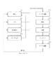
図1は本発明第1の実施例を示す概略図であり、ステップアンドスキャン方式の露光装置をモデルとしている。本発明の特徴は、投影光学系12の瞳面近傍のレンズに石英12sを使用し、インテグレータ400をマイクロアレイとしている点である。
FIG. 1 is a schematic diagram showing a first embodiment of the present invention, which is modeled on a step-and-scan type exposure apparatus. A feature of the present invention is that
従来(図12)に示すインテグレータの場合、インテグレータの瞳分割数はσ1.0に対して50分割程度で、σ0.3以上の照明条件では投影光学系瞳面近傍のエネルギー密度は0.1mJ/cm2以下で問題ない。しかし、σ0.3以下の照明条件では0.1mJ/cm2以上となって、コンパクションによる結像性能の悪化や、耐久性への悪影響が懸念される。 In the case of the integrator shown in FIG. 12 (FIG. 12), the number of pupil divisions of the integrator is about 50 with respect to σ1.0, and the energy density in the vicinity of the projection optical system pupil plane is 0.1 mJ / There is no problem if it is less than cm2. However, it becomes 0.1 mJ / cm 2 or more under illumination conditions of σ 0.3 or less, and there is a concern that the imaging performance is deteriorated due to compaction and the durability is adversely affected.
一方、本発明ではマイクロアレイ400を使用することで、σ0.3の照明条件でもエネルギー密度を0.1mJ/cm2以下に低減することを可能としている。
On the other hand, in the present invention, by using the
本発明の露光装置で用いる第1実施形態のマイクロアレイ詳細を図6に示す。微小なレンズを2次元的に複数配置したシート状構成をしており、微小レンズの開口は、照明形状の略相似形である。 FIG. 6 shows details of the microarray of the first embodiment used in the exposure apparatus of the present invention. It has a sheet-like configuration in which a plurality of minute lenses are two-dimensionally arranged, and the opening of the minute lens is substantially similar to the illumination shape.
走査型露光装置の照明形状は、一般的にスキャン方向(Y方向)が短く、X方向が長い形状としているので、微小レンズの開口形状もX方向に長い形状としている。 Since the illumination shape of the scanning exposure apparatus is generally short in the scanning direction (Y direction) and long in the X direction, the aperture shape of the micro lens is also long in the X direction.
マイクロアレイは、2枚のシートから成り、入射側の1枚は、その入射面に曲率を持たせ、射出面は平板である。射出側のもう1枚は、入射面が平板で、射出面に曲率を持たせている。 The microarray is composed of two sheets. One incident side has a curvature on the incident surface, and the exit surface is a flat plate. The other surface on the exit side has a flat entrance surface and a curvature on the exit surface.
さて、投影光学系の瞳面におけるエネルギー密度を低減するためには、分割数を上げて、各集光点の光量を下げることに、大きな効果がある。更には、X方向の分割数を上げることで、ウェハ上で形成される像のデフォーカス倍率(所謂、倍率テレセン度)の照明モード間差を低減する効果もある。 Now, in order to reduce the energy density on the pupil plane of the projection optical system, there is a great effect in increasing the number of divisions and decreasing the amount of light at each condensing point. Furthermore, by increasing the number of divisions in the X direction, there is an effect of reducing the difference between illumination modes in the defocus magnification (so-called magnification telecentricity) of the image formed on the wafer.
しかし、分割数を上げすぎると、各々の微小レンズから発する光束がウェハ上で干渉を起こし、パターン形成に悪影響を及ぼす。 However, if the number of divisions is increased too much, the light beam emitted from each microlens causes interference on the wafer, which adversely affects pattern formation.
この現象を以下に詳述する。 This phenomenon will be described in detail below.
オプティカルインテグレータに入射する光のコヒーレント長によっては、生成された多数の2次光源の特定の間隔以内に接近した点光源から進む光同志が互いに干渉し合うことがある。この干渉によってレチクル上やウェハ上に、多数の2次光源の配列方向に対応した1次元または2次元の干渉縞が現れる。この干渉縞の鮮明度はレーザ光のコヒーレント長に依存する。レーザ光がエキシマレーザの場合には、光の可干渉性が比較的弱いので、隣接する2次光源同士のみが弱く干渉し合うと考えられる。 Depending on the coherent length of light incident on the optical integrator, light beams traveling from point light sources that are close to each other within a specific interval among the many generated secondary light sources may interfere with each other. Due to this interference, one-dimensional or two-dimensional interference fringes corresponding to the arrangement direction of many secondary light sources appear on the reticle or wafer. The definition of the interference fringes depends on the coherent length of the laser light. When the laser light is an excimer laser, the coherence of the light is relatively weak, so it is considered that only adjacent secondary light sources interfere weakly.
この干渉縞を抑制するため、照明光学系には特別の工夫を施している。例えば、光路途中に配した反射ミラーの角度を振動させたり、光路中に配した偏角素子を光軸を中心に回転させる手段である。これは、干渉縞を移動させることとなり、レーザ光の照度分布を露光時間を通して均一化して、見かけ上の干渉縞を抑える効果がある。 In order to suppress this interference fringe, a special device is applied to the illumination optical system. For example, it is means for oscillating the angle of a reflection mirror disposed in the middle of the optical path or rotating a declination element disposed in the optical path around the optical axis. This moves the interference fringes, and has the effect of making the illuminance distribution of the laser light uniform over the exposure time and suppressing the apparent interference fringes.
いま、オプティカルインテグレータを構成する微小レンズで形成されるx方向集光点の間隔をFxとする。この間隔Fxは、微小レンズの径で決定される。使用波長はλ、コンデンサーレンズの焦点距離をfとする。 Now, let Fx be the distance between the x-direction condensing points formed by the microlenses constituting the optical integrator. This interval Fx is determined by the diameter of the microlens. The wavelength used is λ, and the focal length of the condenser lens is f.
NAを持たない平行光がオプティカルインテグレータに入射したとき、レチクル上に発生する干渉縞は、オプティカルインテグレータの集光点のフーリエ変換となり、x方向のピッチPxは、Px=f・λ/Fxで与えられる。 When parallel light having no NA is incident on the optical integrator, the interference fringes generated on the reticle become the Fourier transform of the focal point of the optical integrator, and the pitch Px in the x direction is given by Px = f · λ / Fx It is done.
これを、前述の干渉縞移動手段で露光時間内に例えばN回移動させれば、干渉縞ピッチはPx/Nと狭まり、均一化を図ることが出来る。 If this is moved, for example, N times within the exposure time by the above-described interference fringe moving means, the interference fringe pitch is narrowed to Px / N and can be made uniform.
微小レンズのピッチFxを無闇に細かくすると、レチクル上(最終的にはウェハ上)のピッチPxが大きくなるため、露光時間内に移動させる回数をそれに応じて上げる必要がある。しかし、干渉縞移動手段の駆動速度には限界がある。 If the pitch Fx of the microlenses is finely reduced, the pitch Px on the reticle (finally on the wafer) increases, so that the number of movements within the exposure time must be increased accordingly. However, the driving speed of the interference fringe moving means is limited.
以上を鑑みて、マイクロアレイX方向の分割数Mは、瞳面でのσ1.0に対して100≦M≦300となるように設定している。 In view of the above, the division number M in the microarray X direction is set to satisfy 100 ≦ M ≦ 300 with respect to σ1.0 on the pupil plane.
一方、Y方向の分割数は、スキャン露光中に複数パルス照射することで、X方向よりも更なる干渉縞の低減効果がある。従って、Y方向の分割数は、X方向より多くすることが可能である。 On the other hand, the number of divisions in the Y direction is more effective in reducing interference fringes than in the X direction by irradiating a plurality of pulses during scan exposure. Therefore, the number of divisions in the Y direction can be larger than that in the X direction.
図6で考えている微小レンズの開口形状は、照射形状と略相似形であるので、Y方向の分割数はX方向の分割数からほぼ一意的に決定される。例えば、照明形状のX方向長さとY方向長さの比が3:1であれば、Y方向の分割数Nは300≦N≦900となる。 Since the aperture shape of the micro lens considered in FIG. 6 is substantially similar to the irradiation shape, the number of divisions in the Y direction is almost uniquely determined from the number of divisions in the X direction. For example, if the ratio of the length in the X direction and the length in the Y direction of the illumination shape is 3: 1, the division number N in the Y direction is 300 ≦ N ≦ 900.
図7は本発明第2の実施例となるマイクロアレイである。2枚のシート構成である。入射側の1枚は、入射面がY方向に曲率を有したマイクロシリンドリカルレンズ、射出面がX方向に曲率を有したマイクロシリンドリカルレンズとなっている。そして各々のマイクロシリンドリカルレンズは、入射面はY方向に曲率を有し、射出面はX方向に曲率を有してそれぞれ配列されている。 FIG. 7 shows a microarray according to a second embodiment of the present invention. A two-sheet configuration. One lens on the incident side is a micro cylindrical lens whose entrance surface has a curvature in the Y direction, and a micro cylindrical lens whose exit surface has a curvature in the X direction. In each micro cylindrical lens, the incident surface has a curvature in the Y direction, and the exit surface has a curvature in the X direction.
射出側のもう1枚も同様に入射面にY方向マイクロシリンドリカルレンズ、射出面にX方向マイクロシリンドリカルレンズをそれぞれ配置している。 Similarly, the other lens on the exit side has a Y-direction micro cylindrical lens on the entrance surface and an X-direction micro cylindrical lens on the exit surface.
インテグレータ射出面近傍に形成される集光点を考えた場合、X方向を最終段に配置すれば、シリンドリカルレンズのバックフォーカスはX方向に短く、Y方向に長くなる。射出NAの大きいX方向でバックフォーカスを小さく出来れば、球面収差を抑えることが効果が大きく、ウェハ面におけるX方向照度分布を均一化するのに有利である。一方、Y方向は射出NAが小さいので、バックフォーカスを長くしても球面収差の悪化は大きくない。更にY方向はスキャン露光で平均化されるため、Y方向の照度分布も十分小さく抑えることが可能となる。 Considering the condensing point formed near the exit surface of the integrator, if the X direction is arranged at the final stage, the back focus of the cylindrical lens is short in the X direction and long in the Y direction. If the back focus can be reduced in the X direction with a large exit NA, it is effective to suppress the spherical aberration, and this is advantageous for making the X direction illuminance distribution uniform on the wafer surface. On the other hand, since the exit NA is small in the Y direction, the spherical aberration is not greatly deteriorated even if the back focus is lengthened. Furthermore, since the Y direction is averaged by scanning exposure, the illuminance distribution in the Y direction can be suppressed sufficiently small.
以上から、シリンドリカルのマイクロアレイを使用する場合には、X方向に対応する曲率を有する面を最終面に配置することが望ましい。 From the above, when a cylindrical microarray is used, it is desirable to arrange a surface having a curvature corresponding to the X direction on the final surface.
しかしながら、後段のコンデンサーレンズや、インテグレータ〜ウェハ面までのコーティング特性とのマッチングを考慮してY方向に対応する面を最終面に用いても構わない。 However, the surface corresponding to the Y direction may be used as the final surface in consideration of matching with the subsequent condenser lens and the coating characteristics from the integrator to the wafer surface.
また、2枚のシートで構成されているマイクロシリンドリカルアレイにおいて、1枚目の入射面と射出面、2枚目の入射面と射出面の曲率を製造工程の効率化のためにそれぞれ等しくしたい場合には、Y−X−Y−XもしくはX−Y−X−Yの配置が必要となる。 In addition, in a micro-cylindrical array composed of two sheets, when it is desired to make the curvature of the first incident surface and the exit surface equal to each other in order to increase the manufacturing process efficiency Requires an arrangement of Y-X-Y-X or XY-XY.
ここで、図7におけるX方向の分割数Mは、図6と同様にウェハにおける干渉縞を考慮して100≦M≦300としている。 Here, the division number M in the X direction in FIG. 7 is set to 100 ≦ M ≦ 300 in consideration of the interference fringes in the wafer as in FIG.
シリンドリカルレンズなので、Y方向の曲率は、X方向の曲率に必ずしも合わせる必要はない。従って、Y方向の分割数Nは、X方向の分割数Mに関係なく自由に設定可能である。よって、XとY方向で分割数が等しい構成としてもよいし、XとY方向で分割数が異なる構成としてもよい。 Since it is a cylindrical lens, the curvature in the Y direction does not necessarily match the curvature in the X direction. Therefore, the division number N in the Y direction can be freely set regardless of the division number M in the X direction. Therefore, the number of divisions may be the same in the X and Y directions, or the number of divisions may be different in the X and Y directions.
以上、インテグレータのマイクロアレイ化の構成について説明したが、次にその効果を説明する。 The configuration of the microarray of the integrator has been described above. Next, the effect will be described.
図8はマイクロアレイインテグレータの場合の、投影系瞳面付近におけるエネルギー分布をあらわしたものである。 FIG. 8 shows the energy distribution in the vicinity of the projection system pupil plane in the case of the microarray integrator.
従来インテグレータのエネルギー分布(図5)に比べて分割数が多くなっており、エネルギー密度も低く抑えられている。 Compared to the energy distribution of conventional integrators (FIG. 5), the number of divisions is large, and the energy density is also kept low.
従って、投影光学系の瞳面に石英を用いることが可能となる。これは、高NAの投影光学系を瞳面の有効径制約を受けることなしに実現できるため、より高品位の結像性能を有する投影光学系を提供することが可能となる。 Therefore, quartz can be used for the pupil plane of the projection optical system. This can be realized without a restriction on the effective diameter of the pupil plane, so that it is possible to provide a projection optical system having higher image quality.
また、石英レンズにおけるエネルギー密度を所望の値(例えば、0.1mJ/cm2)以下に抑えることが出来るため、良好な結像性能を長期間にわたり維持することが可能となる。更には、倍率テレセン度の照明モード間差もより小さく抑えることが可能となる。 In addition, since the energy density in the quartz lens can be suppressed to a desired value (for example, 0.1 mJ / cm 2) or less, it is possible to maintain good imaging performance over a long period of time. Furthermore, the difference between the illumination modes in the magnification telecentricity can be further reduced.
次に上記説明した露光装置を利用した露光方法を図9のフローチャートで説明する。 Next, an exposure method using the above-described exposure apparatus will be described with reference to the flowchart of FIG.
まず、レチクル無しの条件で、それぞれの照明条件におけるウェハ面照度と投影光学系瞳面光強度の関係を予め設計時の計算で求めておく(Step1)。次に、露光装置にて、使用する照明条件とレチクルをセットする(Step2)。そして、使用するレチクルの透過率を、レチクル無し時のウェハ面照度とレチクル有り時のウェハ面照度を計測して、その比率から算出する。ウェハ面照度の計測は、ウェハステージ15上にあるディテクタ16を使用し、レチクルステージ11をスキャンさせたときの平均光量(もしくは積算光量)で行う(Step3)。
First, under the condition of no reticle, the relationship between the wafer surface illuminance and the projection optical system pupil surface light intensity under each illumination condition is obtained in advance by calculation at the time of design (Step 1). Next, the illumination conditions and the reticle to be used are set in the exposure apparatus (Step 2). Then, the transmittance of the reticle to be used is calculated from the ratio obtained by measuring the wafer surface illuminance without the reticle and the wafer surface illuminance with the reticle. The wafer surface illuminance is measured by using the
更に、Step1とStep3の結果から、使用レチクルと使用照明条件における投影光学系瞳面光強度が閾値(例えば、0.1mJ/cm2)以下であるかを判定する(Step4)。最後に、閾値判定に基づき、それぞれ以下のように露光を行う(Step5)。つまり、閾値以下の場合、ウェハステージ15の走査速度が最大となるウェハ照度となるようにND2を選択して露光を行う。そして、閾値以上の場合、投影系瞳面系瞳面光強度が閾値以下となるウェハ照度で、ウェハステージ15の走査速度が最大となるND2を選択して露光を行う。
Further, it is determined from the results of Step 1 and Step 3 whether the projection optical system pupil plane light intensity under the use reticle and the use illumination condition is equal to or less than a threshold (for example, 0.1 mJ / cm 2) (Step 4). Finally, based on the threshold determination, exposure is performed as follows (Step 5). That is, when the value is equal to or less than the threshold value, exposure is performed by selecting ND2 so that the wafer illumination intensity at which the scanning speed of the
次に、上記説明した露光装置を利用したデバイスの製造方法の実施例を説明する。 Next, an embodiment of a device manufacturing method using the above-described exposure apparatus will be described.
図10は本発明のデバイス(ICやLSI等の半導体素子、CCD、或いは液晶素子や磁性材などの微細パターン等)の製造方法のフローチャートである。これについて説明する。 FIG. 10 is a flowchart of a method for manufacturing a device of the present invention (a semiconductor element such as an IC or LSI, a CCD, or a fine pattern such as a liquid crystal element or a magnetic material). This will be described.
ステップ1(回路設計)では、半導体デバイスなどの回路設計を行う。ステップ2(マスク製作)では、設計した回路パターンを形成したマスクを製作する。一方、ステップ3(基板製造)ではシリコン等の材料を用いて、ウェハ等の基板を製造する。ステップ4(ウェハプロセス)は前工程と呼ばれ、本発明の露光装置を用い、前記の用意した回路パターン(第1物体)を形成したマスク(レチクル)とウェハ(第2物体)を用いてリソグラフィ技術によってウェハ上に実際の回路を形成する。ステップ5(組立)は後工程と呼ばれ、ステップ4によって製作されたウェハを用いて半導体チップ化する工程であり、アッセンブリ工程(ダイシング、ボンディング)、パッケージング工程(チップ封入)等の工程を含む。ステップ6(検査)では、ステップ5で作製された半導体デバイスの動作確認テスト、耐久性テスト等の検査を行う。こうした工程を経て、半導体デバイスが完成し、これが出荷(ステップ7)される。
In step 1 (circuit design), a circuit design of a semiconductor device or the like is performed. In step 2 (mask production), a mask on which the designed circuit pattern is formed is produced. On the other hand, in step 3 (substrate manufacture), a substrate such as a wafer is manufactured using a material such as silicon. Step 4 (wafer process) is called a pre-process, and lithography is performed using the mask (reticle) and the wafer (second object) on which the prepared circuit pattern (first object) is formed using the exposure apparatus of the present invention. The actual circuit is formed on the wafer by technology. Step 5 (assembly) is called a post-process, and is a process for forming a semiconductor chip using the wafer manufactured in step 4, and includes processes such as an assembly process (dicing and bonding) and a packaging process (chip encapsulation). . In step 6 (inspection), the semiconductor device manufactured in
次に、図11は上記のウエハプロセスのフローチャートである。ステップ11(酸化)ではウエハの表面を酸化させる。ステップ12(CVD)ではウエハ表面に絶縁膜を形成する。ステップ13(電極形成)ではウエハ上に電極を蒸着によって形成する。ステップ14(イオン打込み)ではウエハにイオンを打ち込む。ステップ15(レジスト処理)ではウエハに感光剤を塗布する。ステップ16(露光)では本発明の露光装置によってレチクルの回路パターンをウエハに焼付露光する。ステップ17(現像)では露光したウエハを現像する。ステップ18(エッチング)では現像したレジスト以外の部分を削り取る。ステップ19(レジスト剥離)ではエッチングがすんで不要となったレジストを取り除く。これらのステップを繰り返し行なうことによってウエハ上に多重に回路パターンが形成される。 Next, FIG. 11 is a flowchart of the wafer process. In step 11 (oxidation), the wafer surface is oxidized. In step 12 (CVD), an insulating film is formed on the wafer surface. In step 13 (electrode formation), an electrode is formed on the wafer by vapor deposition. In step 14 (ion implantation), ions are implanted into the wafer. In step 15 (resist process), a photosensitive agent is applied to the wafer. In step 16 (exposure), the reticle circuit pattern is printed onto the wafer by exposure using the exposure apparatus of the present invention. In step 17 (development), the exposed wafer is developed. In step 18 (etching), portions other than the developed resist are removed. In step 19 (resist stripping), the resist that has become unnecessary after etching is removed. By repeating these steps, multiple circuit patterns are formed on the wafer.
以上の実施例によれば、高NAにおいても瞳面で十分な有効径を有しつつ、色収差を良好に補正する投影光学系を実現することが可能となる。従って、設計的、製造的な制約を緩和することが可能となり、より高品位の結像性能を有する投影光学系を提供することが可能となる。 According to the above-described embodiments, it is possible to realize a projection optical system that can satisfactorily correct chromatic aberration while having a sufficient effective diameter on the pupil plane even at high NA. Therefore, design and manufacturing restrictions can be relaxed, and a projection optical system having higher quality imaging performance can be provided.
また、瞳面における発光部が小さい照明条件(小σ、二重極照明など)においても、ウェハ面照度を高効率に維持することが可能となり、デバイスの生産性に有効となる。 Further, even under illumination conditions (small σ, dipole illumination, etc.) where the light emitting part on the pupil plane is small, the wafer surface illuminance can be maintained with high efficiency, which is effective for device productivity.
以上、本発明の好ましい実施例について説明したが、本発明はこれらの実施例に限定されないことはいうまでもなく、その要旨の範囲内で種々の変形及び変更が可能である。 The preferred embodiments of the present invention have been described above, but the present invention is not limited to these embodiments, and various modifications and changes can be made within the scope of the gist.
1 光源
2 減光部材
3 ビーム成型光学系
4 オプティカルインテグレータ
400 マイクロアレイオプティカルインテグレータ
5 絞り
6 集光レンズ
7a 可変スリット
7b スキャンブレード
8a、8b 結像レンズ
9 ミラー
10 レチクル
11 レチクルステージ
12 投影光学系
12a〜z 投影光学系を構成する透過部材
14 ウェハ
15 ウェハステージ
16 ディテクタ
17 積算露光量センサ
18 ハーフミラー
21 ND駆動手段
22 レンズ系駆動手段
23 絞り駆動手段
24 スキャンブレード駆動装置
25 レチクルステージ駆動装置
27 ウェハステージ駆動装置
30 主制御装置
DESCRIPTION OF SYMBOLS 1 Light source 2 Dimming member 3 Beam shaping optical system 4
Claims (12)
前記照明光学系は、前記光源からの光を用いて2次光源を形成するオプティカルインテグレータと、前記オプティカルインテグレータからの光を前記原板に導光するコンデンサー光学系とを備え
前記投影光学系は、瞳面近傍に石英部材を用いていることを特徴とする投影露光装置。 A projection exposure apparatus that includes an illumination optical system that illuminates an original plate with light from a light source and a projection optical system that projects a pattern of the original plate onto a substrate, and performs exposure by relatively scanning the original plate and the substrate. And
The illumination optical system includes: an optical integrator that forms a secondary light source using light from the light source; and a condenser optical system that guides the light from the optical integrator to the original plate. A projection exposure apparatus using a quartz member in the vicinity of a surface.
100≦M≦300且つM≦N
を満たすことを特徴とする請求項1又は2記載の投影露光装置。 The optical integrator is a type of wavefront division, and the number of divisions is N division in the scanning direction and M division in the direction orthogonal to the scanning direction on the projection optical system pupil plane.
100 ≦ M ≦ 300 and M ≦ N
The projection exposure apparatus according to claim 1, wherein:
Priority Applications (3)
| Application Number | Priority Date | Filing Date | Title |
|---|---|---|---|
| JP2004123870A JP2005310942A (en) | 2004-04-20 | 2004-04-20 | Aligner, exposure method, and device manufacturing method using it |
| US11/110,350 US7242457B2 (en) | 2004-04-20 | 2005-04-19 | Exposure apparatus and exposure method, and device manufacturing method using the same |
| EP05252428A EP1589378A3 (en) | 2004-04-20 | 2005-04-19 | Exposure apparatus and exposure method and device manufacturing method using the same |
Applications Claiming Priority (1)
| Application Number | Priority Date | Filing Date | Title |
|---|---|---|---|
| JP2004123870A JP2005310942A (en) | 2004-04-20 | 2004-04-20 | Aligner, exposure method, and device manufacturing method using it |
Publications (2)
| Publication Number | Publication Date |
|---|---|
| JP2005310942A true JP2005310942A (en) | 2005-11-04 |
| JP2005310942A5 JP2005310942A5 (en) | 2007-05-31 |
Family
ID=34940903
Family Applications (1)
| Application Number | Title | Priority Date | Filing Date |
|---|---|---|---|
| JP2004123870A Abandoned JP2005310942A (en) | 2004-04-20 | 2004-04-20 | Aligner, exposure method, and device manufacturing method using it |
Country Status (3)
| Country | Link |
|---|---|
| US (1) | US7242457B2 (en) |
| EP (1) | EP1589378A3 (en) |
| JP (1) | JP2005310942A (en) |
Cited By (2)
| Publication number | Priority date | Publication date | Assignee | Title |
|---|---|---|---|---|
| JP2009236819A (en) * | 2008-03-28 | 2009-10-15 | Topcon Corp | Optical apparatus, photomask inspection device, and exposure device |
| WO2013051147A1 (en) * | 2011-10-07 | 2013-04-11 | キヤノン株式会社 | Image acquisition apparatus adjustment method, image acquisition apparatus, and image acquisition apparatus manufacturing method |
Families Citing this family (4)
| Publication number | Priority date | Publication date | Assignee | Title |
|---|---|---|---|---|
| ATE511668T1 (en) * | 2004-02-17 | 2011-06-15 | Zeiss Carl Smt Gmbh | ILLUMINATION SYSTEM FOR A MICROLITHOGRAPHIC PROJECTION EXPOSURE DEVICE |
| US20080225257A1 (en) * | 2007-03-13 | 2008-09-18 | Nikon Corporation | Optical integrator system, illumination optical apparatus, exposure apparatus, and device manufacturing method |
| JP4261591B2 (en) * | 2007-03-30 | 2009-04-30 | アドバンスド・マスク・インスペクション・テクノロジー株式会社 | Illumination optical apparatus and sample inspection apparatus |
| KR101300733B1 (en) * | 2012-01-12 | 2013-08-27 | 연세대학교 산학협력단 | multi parallel confocal systeme |
Family Cites Families (13)
| Publication number | Priority date | Publication date | Assignee | Title |
|---|---|---|---|---|
| US6404482B1 (en) * | 1992-10-01 | 2002-06-11 | Nikon Corporation | Projection exposure method and apparatus |
| US5684566A (en) | 1995-05-24 | 1997-11-04 | Svg Lithography Systems, Inc. | Illumination system and method employing a deformable mirror and diffractive optical elements |
| US5724122A (en) | 1995-05-24 | 1998-03-03 | Svg Lithography Systems, Inc. | Illumination system having spatially separate vertical and horizontal image planes for use in photolithography |
| JP3641767B2 (en) | 1996-07-02 | 2005-04-27 | 信越石英株式会社 | Exposure apparatus for integrated circuit manufacturing |
| JP3976083B2 (en) | 1997-03-25 | 2007-09-12 | 信越石英株式会社 | Optical system for circuit pattern exposure |
| AU6853598A (en) * | 1997-04-18 | 1998-11-13 | Nikon Corporation | Aligner, exposure method using the aligner, and method of manufacture of circuitdevice |
| US6583937B1 (en) * | 1998-11-30 | 2003-06-24 | Carl-Zeiss Stiftung | Illuminating system of a microlithographic projection exposure arrangement |
| DE19855106A1 (en) | 1998-11-30 | 2000-05-31 | Zeiss Carl Fa | Illumination system for VUV microlithography |
| DE10062579A1 (en) | 1999-12-15 | 2001-06-21 | Nikon Corp | Optical integrator of wave front subdividing type used for photolithographic illuminating device comprises micro-optical elements arranged two-dimensionally to form light sources by subdividing wave front of falling light beam |
| US6788389B2 (en) | 2001-07-10 | 2004-09-07 | Nikon Corporation | Production method of projection optical system |
| JP3634782B2 (en) * | 2001-09-14 | 2005-03-30 | キヤノン株式会社 | Illumination apparatus, exposure apparatus using the same, and device manufacturing method |
| JP4324957B2 (en) * | 2002-05-27 | 2009-09-02 | 株式会社ニコン | Illumination optical apparatus, exposure apparatus, and exposure method |
| JP2004259786A (en) * | 2003-02-24 | 2004-09-16 | Canon Inc | Aligner |
-
2004
- 2004-04-20 JP JP2004123870A patent/JP2005310942A/en not_active Abandoned
-
2005
- 2005-04-19 EP EP05252428A patent/EP1589378A3/en not_active Withdrawn
- 2005-04-19 US US11/110,350 patent/US7242457B2/en not_active Expired - Fee Related
Cited By (2)
| Publication number | Priority date | Publication date | Assignee | Title |
|---|---|---|---|---|
| JP2009236819A (en) * | 2008-03-28 | 2009-10-15 | Topcon Corp | Optical apparatus, photomask inspection device, and exposure device |
| WO2013051147A1 (en) * | 2011-10-07 | 2013-04-11 | キヤノン株式会社 | Image acquisition apparatus adjustment method, image acquisition apparatus, and image acquisition apparatus manufacturing method |
Also Published As
| Publication number | Publication date |
|---|---|
| EP1589378A2 (en) | 2005-10-26 |
| US7242457B2 (en) | 2007-07-10 |
| US20050231702A1 (en) | 2005-10-20 |
| EP1589378A3 (en) | 2007-05-23 |
Similar Documents
| Publication | Publication Date | Title |
|---|---|---|
| JP3826047B2 (en) | Exposure apparatus, exposure method, and device manufacturing method using the same | |
| JP5159027B2 (en) | Illumination optical system and exposure apparatus | |
| EP1429190A2 (en) | Exposure apparatus and method | |
| US20060176461A1 (en) | Projection optical system and exposure apparatus having the same | |
| JP3413160B2 (en) | Illumination apparatus and scanning exposure apparatus using the same | |
| JP2006245157A (en) | Exposure method and device | |
| US7518707B2 (en) | Exposure apparatus | |
| JP4095376B2 (en) | Exposure apparatus and method, and device manufacturing method | |
| JP2007158225A (en) | Aligner | |
| JP2007242775A (en) | Exposure device, and method of manufacturing device | |
| JP2007299993A (en) | Aligner | |
| US7242457B2 (en) | Exposure apparatus and exposure method, and device manufacturing method using the same | |
| JP4366163B2 (en) | Illumination apparatus and exposure apparatus | |
| JP4684563B2 (en) | Exposure apparatus and method | |
| JP3997199B2 (en) | Exposure method and apparatus | |
| JP2004055856A (en) | Lighting device, manufacturing method for exposure device and for device utilizing the same | |
| JP2009032747A (en) | Scanning stepper and device manufacturing method | |
| JP3958122B2 (en) | Illumination apparatus, exposure apparatus using the same, and device manufacturing method | |
| JP2005209769A (en) | Aligner | |
| JP2008124308A (en) | Exposure method and exposure apparatus, and device manufacturing method using the same | |
| JP2007158224A (en) | Exposure method | |
| JP2005331651A (en) | Method for forming three-dimensional structure, optical element manufactured by using the same, optical system, apparatus, device and method for manufacturing the device | |
| JP2007189079A (en) | Illuminating optical system, exposure device having it, and manufacturing method of device | |
| JPH09213618A (en) | Projection exposure system and manufacture of device using the same | |
| JP5225433B2 (en) | Illumination optical system and exposure apparatus |
Legal Events
| Date | Code | Title | Description |
|---|---|---|---|
| A521 | Written amendment |
Free format text: JAPANESE INTERMEDIATE CODE: A523 Effective date: 20070409 |
|
| A621 | Written request for application examination |
Free format text: JAPANESE INTERMEDIATE CODE: A621 Effective date: 20070409 |
|
| A977 | Report on retrieval |
Free format text: JAPANESE INTERMEDIATE CODE: A971007 Effective date: 20090929 |
|
| RD04 | Notification of resignation of power of attorney |
Free format text: JAPANESE INTERMEDIATE CODE: A7424 Effective date: 20100201 |
|
| A762 | Written abandonment of application |
Free format text: JAPANESE INTERMEDIATE CODE: A762 Effective date: 20100208 |