JP2005308512A - Spectrum processing method and measuring apparatus using the same - Google Patents
Spectrum processing method and measuring apparatus using the same Download PDFInfo
- Publication number
- JP2005308512A JP2005308512A JP2004124969A JP2004124969A JP2005308512A JP 2005308512 A JP2005308512 A JP 2005308512A JP 2004124969 A JP2004124969 A JP 2004124969A JP 2004124969 A JP2004124969 A JP 2004124969A JP 2005308512 A JP2005308512 A JP 2005308512A
- Authority
- JP
- Japan
- Prior art keywords
- frequency
- signal
- spectrum
- phase
- phase noise
- Prior art date
- Legal status (The legal status is an assumption and is not a legal conclusion. Google has not performed a legal analysis and makes no representation as to the accuracy of the status listed.)
- Pending
Links
Images


Classifications
-
- G—PHYSICS
- G01—MEASURING; TESTING
- G01R—MEASURING ELECTRIC VARIABLES; MEASURING MAGNETIC VARIABLES
- G01R23/00—Arrangements for measuring frequencies; Arrangements for analysing frequency spectra
- G01R23/16—Spectrum analysis; Fourier analysis
- G01R23/165—Spectrum analysis; Fourier analysis using filters
- G01R23/167—Spectrum analysis; Fourier analysis using filters with digital filters
-
- G—PHYSICS
- G01—MEASURING; TESTING
- G01R—MEASURING ELECTRIC VARIABLES; MEASURING MAGNETIC VARIABLES
- G01R23/00—Arrangements for measuring frequencies; Arrangements for analysing frequency spectra
- G01R23/16—Spectrum analysis; Fourier analysis
- G01R23/18—Spectrum analysis; Fourier analysis with provision for recording frequency spectrum
-
- G—PHYSICS
- G01—MEASURING; TESTING
- G01R—MEASURING ELECTRIC VARIABLES; MEASURING MAGNETIC VARIABLES
- G01R23/00—Arrangements for measuring frequencies; Arrangements for analysing frequency spectra
- G01R23/16—Spectrum analysis; Fourier analysis
- G01R23/20—Measurement of non-linear distortion
-
- G—PHYSICS
- G01—MEASURING; TESTING
- G01R—MEASURING ELECTRIC VARIABLES; MEASURING MAGNETIC VARIABLES
- G01R29/00—Arrangements for measuring or indicating electric quantities not covered by groups G01R19/00 - G01R27/00
- G01R29/26—Measuring noise figure; Measuring signal-to-noise ratio
Abstract
Description
本発明は、測定装置において、被測定信号から得られるスペクトラムであって線形的に等間隔な周波数に対応するスペクトラムを、対数的に等間隔な周波数に対応させる方法に関する。また、本発明は、該方法を用いる測定装置に関する。 The present invention relates to a method of causing a spectrum obtained from a signal under measurement and corresponding to a linearly equidistant frequency to correspond to a logarithmically equidistant frequency in a measuring apparatus. The present invention also relates to a measuring apparatus using the method.
従来の位相雑音測定装置は、該測定装置内部に位相雑音源があって、位相雑音の測定精度に限界があった。従来、その内部位相雑音が測定結果に及ぼす影響を低減するために、位相雑音測定装置を低位相雑音特性を有する部品で構成していた。また、位相雑音測定装置の内部で発生する位相雑音を誤差成分として予め求め、その誤差成分を用いて測定結果を補正することも実施されていた(例えば、特許文献1を参照。)。 The conventional phase noise measuring apparatus has a phase noise source inside the measuring apparatus, and there is a limit to the measurement accuracy of the phase noise. Conventionally, in order to reduce the influence of the internal phase noise on the measurement result, the phase noise measuring apparatus is configured with components having low phase noise characteristics. In addition, phase noise generated inside the phase noise measuring apparatus is obtained in advance as an error component, and the measurement result is corrected using the error component (see, for example, Patent Document 1).
しかし、上記の位相雑音測定装置には、幾つかの問題があった。まず、従来の位相雑音測定装置は、要求される位相雑音特性を達成できなくなってきている。位相雑音測定において要求される測定可能な下限雑音レベルは、年々下がっている。例えば、現在では、−135dBc/Hz(@10KHzオフセット、1GHzキャリア)程度の位相雑音特性が要求されている。ところが、低位相雑音特性を有する部品で位相雑音測定装置を構成する場合、該部品に起因して発生する雑音はゼロではないので、位相雑音測定装置の性能向上には限界がある。予め調べた位相雑音成分を用いて測定結果を補正する場合であっても、位相雑音測定装置の内部で発生する位相雑音成分を完全に除去することはできない。 However, the above phase noise measuring apparatus has several problems. First, the conventional phase noise measuring apparatus cannot achieve the required phase noise characteristics. The measurable lower limit noise level required in phase noise measurement is decreasing year by year. For example, at present, phase noise characteristics of about −135 dBc / Hz (@ 10 KHz offset, 1 GHz carrier) are required. However, when a phase noise measuring device is configured with components having low phase noise characteristics, noise generated due to the components is not zero, so there is a limit to improving the performance of the phase noise measuring device. Even when the measurement result is corrected using the phase noise component examined in advance, the phase noise component generated inside the phase noise measuring device cannot be completely removed.
また、従来の位相雑音測定装置は、位相雑音を測定する前に被測定信号に何らかの処理を施す場合、該信号処理に起因して生じる位相雑音が測定結果に及ぼす影響を除去することができない。例えば、測定周波数範囲を拡張するために、位相雑音測定装置の前段にダウンコンバータを付加する場合、位相雑音測定装置は被測定信号の位相雑音に加えて、ダウンコンバータに起因する位相雑音も測定してしまう。感度を向上させるために、位相雑音測定装置の前段にアンプを付加する場合にも、同様のことが言える。位相雑音測定装置内の位相雑音検出部の前段に、これらの付加装置または付加回路を設ける場合にも、同様のことが言える。これらの付加装置や付加回路が発生する位相雑音は、予め求めておくことが困難な場合が多い。従って、これらの付加装置や付加回路が測定結果に及ぼす影響を低減するためには、これらの付加装置や付加回路を低位相雑音特性を有する部品で構成せざるを得ない。 In addition, when the conventional phase noise measuring apparatus performs some processing on the signal under measurement before measuring the phase noise, the influence of the phase noise generated due to the signal processing on the measurement result cannot be removed. For example, when a down converter is added before the phase noise measurement device to extend the measurement frequency range, the phase noise measurement device measures the phase noise caused by the down converter in addition to the phase noise of the signal under measurement. End up. The same can be said when an amplifier is added in front of the phase noise measuring device in order to improve sensitivity. The same can be said when these additional devices or additional circuits are provided in front of the phase noise detector in the phase noise measuring device. The phase noise generated by these additional devices and additional circuits is often difficult to obtain in advance. Therefore, in order to reduce the influence of these additional devices and additional circuits on the measurement results, these additional devices and additional circuits must be configured with parts having low phase noise characteristics.
位相雑音を低減するための方策として、従来採られてきたものは、以下の通りである。すなわち、装置の各部の雑音を下げるために低雑音特性を有する高価な部品を使用すること、雑音に対するPLLの寄与を分散して雑音を下げるためにPLLを多重化すること、および、出力周波数に応じて最適な装置構成を組むために多くの切り替えを設定すること、などである。これらの方策は、すべて製造コストの上昇をもたらし、その一方で、求められている製造コストの低減に相反するものであった。さらに、上記の方策を講じても実現しえないような低い位相雑音特性を求められることもあり、そのような場合には、いかにコストをかけようとも要求に応えられていないのが現状である。 Conventionally taken as measures for reducing phase noise are as follows. That is, use expensive parts having low noise characteristics to reduce the noise of each part of the device, multiplex the PLL to reduce the noise by distributing the contribution of the PLL to the noise, and the output frequency In response to this, setting a large number of switchings in order to construct an optimum device configuration. All of these measures have resulted in increased manufacturing costs, while contradicting the required reduction in manufacturing costs. In addition, low phase noise characteristics that cannot be realized even if the above measures are taken may be required. In such cases, the current situation is that no matter how much the cost is spent, the request cannot be met. .
そこで、本発明は、上記の課題を解決し、さらに、従来に比べて低いレベルの位相雑音を測定するための方法および装置を提供することを目的とする。また、本発明は、比較的広い周波数範囲の信号に対しても、従来に比べて低いレベルの位相雑音を測定できる方法および装置を提供することを目的とする。 Therefore, the present invention has an object to solve the above-described problems and provide a method and apparatus for measuring phase noise at a lower level than in the past. It is another object of the present invention to provide a method and apparatus that can measure a phase noise of a lower level than that of a conventional signal even in a relatively wide frequency range.
本発明は、上記の目的を達成するためになされたものである。すなわち、本第一の発明は、被測定信号の位相雑音を測定する方法であって、該被測定信号の位相を表す第一の位相信号を生成するステップと、該被測定信号の位相を表す第二の位相信号を生成するステップと、該第一の位相信号と該第二の位相信号とのクロススペクトラムを少なくとも所定回数求めるステップと、該所定数の該クロススペクトラムの平均を求めるステップと、を備えることを特徴とするものである。 The present invention has been made to achieve the above object. That is, the first invention is a method for measuring phase noise of a signal under measurement, the step of generating a first phase signal representing the phase of the signal under measurement, and the phase of the signal under measurement. Generating a second phase signal; determining a cross spectrum of the first phase signal and the second phase signal at least a predetermined number of times; determining an average of the predetermined number of the cross spectrum; It is characterized by providing.
また、本第二の発明は、被測定信号の位相雑音を測定する方法であって、第一の信号処理手段により該被測定信号から第一の中間信号を生成するステップと、該第一の信号処理手段とは別個の第二の信号処理手段により該被測定信号から第二の中間信号を生成するステップと、該第一の中間信号の位相を表す第一の位相信号を生成するステップと、該第二の中間信号の位相を表す第二の位相信号を生成するステップと、該第一の位相信号と該第二の位相信号とのクロススペクトラムを少なくとも所定回数求めるステップと、該所定数の該クロススペクトラムの平均を求めるステップと、を備えることを特徴とするものである。 The second invention is a method for measuring phase noise of a signal under measurement, the first signal processing means generating a first intermediate signal from the signal under measurement, Generating a second intermediate signal from the signal under measurement by a second signal processing means separate from the signal processing means, and generating a first phase signal representing the phase of the first intermediate signal; Generating a second phase signal representing the phase of the second intermediate signal; obtaining a cross spectrum between the first phase signal and the second phase signal at least a predetermined number of times; and the predetermined number And obtaining an average of the cross spectrum.
またさらに、本第三の発明は、被測定信号の位相雑音を測定する方法であって、第一の基準信号を参照して生成される第一の局部信号を用いて、被測定信号の位相を表す第一の位相信号を生成するステップと、該第一の基準信号とは異なる周波数を有する第二の基準信号を参照して生成される第二の局部信号を用いて、該被測定信号の位相を表す第二の位相信号を生成するステップと、該第一の位相信号と該第二の位相信号とのクロススペクトラムを求めるステップと、を含むことを特徴とするものである。 Still further, the third invention is a method for measuring phase noise of a signal under measurement, wherein the phase of the signal under measurement is measured using a first local signal generated with reference to the first reference signal. Using a second local signal generated by referring to a second reference signal having a frequency different from that of the first reference signal. And a step of generating a second phase signal representing the phase of the first phase signal and a step of obtaining a cross spectrum between the first phase signal and the second phase signal.
また、本第四の発明は、本第一の発明方法または本第二の発明方法または本第三の発明方法のいずれかの方法により、被測定信号の位相雑音を測定する装置である。 The fourth invention is an apparatus for measuring the phase noise of a signal under measurement by any one of the first invention method, the second invention method, or the third invention method.
さらに、本第五の発明は、被測定信号から得られる少なくとも2つの位相信号に対して相関処理またはクロススペクトラム処理を施すことにより被測定信号の位相雑音を測定する装置であって、該測定信号を少なくとも2つに分配するための分配器と、第一の位相検出手段と、第二の位相検出手段と、該分配器と該第一の位相検出手段との接続経路を開放するための第一の端子対と、該分配器と該第二の位相検出手段との接続経路を開放するための第二の端子対とを備え、前記第一の端子対および前記第二の端子対は、ともに短絡されるか、それぞれ別個の外部信号処理手段がともに接続されることを特徴とするものである。 Further, the fifth aspect of the invention is an apparatus for measuring phase noise of a signal under measurement by performing correlation processing or cross spectrum processing on at least two phase signals obtained from the signal under measurement, wherein the measurement signal For distributing at least two, first phase detecting means, second phase detecting means, and a first path for opening a connection path between the distributor and the first phase detecting means One terminal pair, and a second terminal pair for opening a connection path between the distributor and the second phase detection means, wherein the first terminal pair and the second terminal pair are: Both are short-circuited, or separate external signal processing means are connected together.
またさらに、本第六の発明は、被測定信号の位相雑音を測定する装置であって、該被測定信号から分配された第一の分配信号の位相を検出する第一の位相検出手段と、該被測定信号から分配された第二の分配信号の位相を検出する、第一の位相検出手段とは別個の第二の位相検出手段と、担当する周波数帯域が異なる複数のクロススペクトラム生成手段とを備え、該クロススペクトラム生成手段は、それぞれが担当する周波数帯域における第一の位相検出手段の出力信号と第二の位相検出手段の出力信号とのクロススペクトラムを求め、前記クロススペクトラム生成手段のそれぞれは、前記第一の位相検出手段の出力信号と前記第二の位相検出手段の出力信号とのクロススペクトラムを同一時間内において繰り返し求め、該時間内に2以上の前記クロススペクトラムが求められた場合、求められた2以上の前記クロススペクトラムに時間方向のベクトル平均を施すことを特徴とするものである。 Still further, the sixth invention is an apparatus for measuring phase noise of a signal under measurement, the first phase detecting means for detecting the phase of the first distribution signal distributed from the signal under measurement, A second phase detection unit separate from the first phase detection unit for detecting a phase of the second distribution signal distributed from the signal under measurement; and a plurality of cross spectrum generation units having different frequency bands in charge The cross spectrum generation means obtains a cross spectrum between the output signal of the first phase detection means and the output signal of the second phase detection means in the frequency band each is responsible for, and each of the cross spectrum generation means Repeatedly calculates the cross spectrum of the output signal of the first phase detection means and the output signal of the second phase detection means within the same time, and two or more within the time If serial cross-spectrum is determined, it is characterized in that two or more of the cross spectrum obtained applying vector averaging in the time direction.
また、本第七の発明は、測定装置において、被測定信号から得られるスペクトラムであって線形的に等間隔な周波数に対応するスペクトラムを、対数的に等間隔な周波数に対応させる方法であって、線形的に等間隔な周波数に対応する該スペクトラムから、対数的に等間隔な周波数から所定の周波数範囲に含まれる該スペクトラムを選択し、選択した該スペクトラムに対してベクトル平均を施すステップ、を含むことを特徴とするものである。 The seventh aspect of the invention is a method for causing a spectrum obtained from a signal under measurement and corresponding to a linearly spaced frequency to correspond to a logarithmically spaced frequency in a measuring apparatus. Selecting the spectrum included in a predetermined frequency range from the logarithmically equidistant frequency from the spectrum corresponding to the linearly equidistant frequency, and performing vector averaging on the selected spectrum. It is characterized by including.
さらに、本第八の発明は、本第七の発明方法により、対数的に等間隔な周波数に対応するスペクトラムを生成することを特徴とする測定装置である。 Furthermore, the eighth invention is a measuring apparatus characterized in that a spectrum corresponding to logarithmically spaced frequencies is generated by the seventh invention method.
なお、本発明の全容は、以下の説明により明らかにされる。 The whole of the present invention will be clarified by the following description.
本発明によれば、相互相関処理またはクロススペクトラム処理を用いて位相雑音を測定するので、従来に比べて低いレベルの位相雑音を測定できるようになる。 According to the present invention, since phase noise is measured using cross-correlation processing or cross spectrum processing, it is possible to measure phase noise at a lower level than in the past.
また、本発明によれば、クロススペクトラムに対して周波数方向の平均処理を施すので、さらに低いレベルの位相雑音を測定できるようになる。 Further, according to the present invention, since average processing in the frequency direction is performed on the cross spectrum, it becomes possible to measure a lower level phase noise.
さらに、本発明によれば、上記の相互相関処理またはクロススペクトラム処理を複数の処理ブロックに分けて実施するので、各処理ブロック毎に単位時間あたりの処理回数を増加させることができ、その結果、単純に相互相関処理またはクロススペクトラム処理を行う場合に比べて、さらに低いレベルの位相雑音を測定できるようになる。 Furthermore, according to the present invention, the cross-correlation process or the cross spectrum process is performed by dividing it into a plurality of processing blocks, so that the number of processes per unit time can be increased for each processing block. As compared with the case where the cross-correlation process or the cross spectrum process is simply performed, it becomes possible to measure the phase noise at a lower level.
またさらに、本発明によれば、相互相関処理またはクロススペクトラム処理を用いて位相雑音を測定する場合に、測定に関与する信号源の基準信号源の周波数を互いに異ならせるので、該信号源によるスプリアスが位相雑音測定値へ及ぼす影響を低減することができる。 Furthermore, according to the present invention, when the phase noise is measured using the cross-correlation process or the cross spectrum process, the frequency of the reference signal source of the signal source involved in the measurement is made different from each other. Can reduce the effect on the measured phase noise.
また、本発明によれば、相互相関処理またはクロススペクトラム処理を用いて位相雑音を測定する場合に、被測定信号を分配し、分配した被測定信号のそれぞれに対して別個の信号処理手段により信号処理するので、該信号処理手段が位相雑音測定値へ及ぼす影響を低減することができる。例えば、信号処理手段が信号源を具備する周波数変換手段である場合、本発明の効果は顕著である。 Further, according to the present invention, when measuring phase noise using cross-correlation processing or cross-spectrum processing, a signal under measurement is distributed, and a signal is processed by a separate signal processing means for each of the distributed signals under measurement. Since the processing is performed, the influence of the signal processing means on the phase noise measurement value can be reduced. For example, when the signal processing means is a frequency conversion means having a signal source, the effect of the present invention is remarkable.
以下、本発明の好適実施形態を、添付の図面を適宜参照しながら、以下に説明する。本発明の第一の実施形態は、位相雑音測定装置100である。ここで、位相雑音測定装置100の構成を示すブロック図を図1に示す。図1において、被測定物10と位相雑音測定装置100とが示されている。
Hereinafter, preferred embodiments of the present invention will be described with reference to the accompanying drawings as appropriate. The first embodiment of the present invention is a phase
被測定物10は、位相雑音の測定対象である被測定信号Vを出力する。被測定物10は、信号源、または、信号が印加される部品もしくは装置もしくはシステムなどである。
The device under
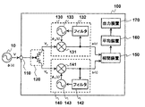
位相雑音測定装置100は、以下のように構成される。すなわち、位相雑音測定装置100は、入力端子110と、分配器120と、位相検出手段の一例であるPLLブロック130と、位相検出手段の一例であるPLLブロック140と、相関装置150と、平均装置160と、出力装置170とを備える。入力端子110は、被測定信号Vを受信するための端子である。分配器120は、入力端子110において受信した被測定信号Vを分配して、PLLブロック130とPLLブロック140とに出力する装置である。PLLブロック130は、分配器120から分配された信号Vaの位相を検出する装置である。PLLブロック130は、ミキサ131とフィルタ132と信号源133とを備える。ミキサ131は、分配信号Vaと信号源133の出力信号とが入力され、それらの信号の位相差を出力する。フィルタ132は、PLLの帯域を制限するループフィルタである。信号源133は、フィルタ132の出力信号に応じて、出力信号の周波数と位相が制御される信号源である。PLLブロック140は、分配器120から分配された信号Vbの位相を検出する装置である。PLLブロック140は、ミキサ141とフィルタ142と信号源143とを備える。ミキサ141は、分配信号Vbと信号源143の出力信号とが入力され、それらの信号の位相差を出力する。フィルタ142は、PLLの帯域を制限するループフィルタである。信号源143は、フィルタ142の出力信号に応じて、出力信号の周波数と位相が制御される信号源である。相関装置150は、PLLブロック130の出力信号である位相信号a(t)とPLLブロック140の出力信号である位相信号b(t)とのクロススペクトラムを求める装置である。ここで、図2を参照しながら、相関装置150について、詳述する。
The phase
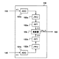
図2は、相関装置150の構成を示すブロック図である。図2において、相関装置150は、アナログ・ディジタル変換器151aと、メモリ152aと、スペクトラム解析手段の一例である高速フーリエ変換器153aと、アナログ・ディジタル変換器151bと、メモリ152bと、スペクトラム解析手段の一例である高速フーリエ変換器153bと、乗算器154とを備える。以下、アナログ・ディジタル変換器をADCと、高速フーリエ変換器をFFTと、それぞれ称する。なお、FFTは、高速フーリエ変換の略称として使用する場合もある。ADC151aは、位相信号a(t)をアナログ・ディジタル変換する装置である。メモリ152aは、ADC151aの変換結果である、ディジタル化された位相信号a(t)を格納する装置である。FFT153aは、メモリ152aに格納された位相信号a(t)をフーリエ変換する。そして、位相信号a(t)のフーリエ変換結果のうち、ナイキスト周波数(fs/2)以下の成分A(f)が乗算器154に出力される。ADC151bは、位相信号b(t)をアナログ・ディジタル変換する装置である。なお、ADC151aおよびADC151bは、同一の変換処理速度fs(サンプル/秒)を有する。メモリ152bは、ADC151bの変換結果である、ディジタル化された位相信号b(t)を格納する装置である。FFT153bは、メモリ152bに格納された位相信号b(t)をフーリエ変換する。そして、位相信号b(t)のフーリエ変換結果のうち、ナイキスト周波数(fs/2)以下の成分B(f)が乗算器154に出力される。なお、FFT153aおよびFFT153bは、同一のポイント数を有する。乗算器154は、フーリエ変換結果A(f)とフーリエ変換結果B(f)とについて次式で表される処理を施す。
FIG. 2 is a block diagram showing the configuration of the

なお、Sab(f)は、a(t)とb(t)とのクロススペクトラムである。また、上付き添え字*は、複素共役を表す。 S ab (f) is a cross spectrum between a (t) and b (t). The superscript * indicates a complex conjugate.
乗算器154の処理結果であるSab(f)は、平均装置160へ出力される。
S ab (f) that is the processing result of the
再び、図1を参照する。平均装置160は、処理結果Sab(f)に対して次式で表される平均処理を施す。
Reference is again made to FIG. The averaging
なお、Nは、1以上の整数である。Sab(k,f)は、k番目に得られるクロススペクトラムSab(f)である。上記のように、複数の複素数を実数部と虚数部とで別個に平均することを、本明細書において「ベクトル平均」という。これに対して、複数の複素数の大きさ(絶対値)またはパワー(絶対値の2乗)を平均することを、「スカラ平均」という。一般的な測定器における「アベレージ」機能は、スカラ平均を用いている。 N is an integer of 1 or more. S ab (k, f) is the kth cross spectrum S ab (f) obtained. As described above, averaging a plurality of complex numbers separately in the real part and the imaginary part is referred to as “vector averaging” in this specification. On the other hand, averaging the magnitude (absolute value) or power (the square of the absolute value) of a plurality of complex numbers is called “scalar average”. The “average” function in a typical measuring instrument uses a scalar average.
出力装置170は、平均装置160の処理結果であるASab(f)を液晶ディスプレイなどの表示装置(不図示)、または、プリンタなどの印刷装置(不図示)、または、LANインタフェースなどの通信装置(不図示)に出力する装置である。
The
ここで、相互相関処理またはクロススペクトラム処理を用いた位相雑音測定の原理について、以下に説明する。まず、被測定信号Vの位相をφ(t)、信号源133の出力信号の位相をφa(t)、信号源143の出力信号の位相をφb(t)とする。この時、位相信号a(t)およびb(t)は、次式のように表される。
Here, the principle of phase noise measurement using cross correlation processing or cross spectrum processing will be described below. First, the phase of the signal to be measured V is φ (t), the phase of the output signal of the
また、位相信号a(t)およびb(t)の相互相関Cab(τ)は次式で表される。 The cross-correlation C ab (τ) between the phase signals a (t) and b (t) is expressed by the following equation.
位相信号a(t)およびb(t)のクロススペクトラムSab(f)は、式(5)で表される相互相関Cab(τ)をフーリエ変換することにより得られる。クロススペクトラムSab(f)の片側スペクトラムは、次式で表される。 The cross spectrum S ab (f) of the phase signals a (t) and b (t) is obtained by performing a Fourier transform on the cross-correlation C ab (τ) expressed by the equation (5). The one-sided spectrum of the cross spectrum S ab (f) is expressed by the following equation.
被測定信号Vの位相φ(t)、信号源133の出力信号の位相φa(t)、および、信号源143の出力信号の位相φb(t)は、互いに独立していると仮定すれば、次式が得られる。
Of the measured signal V phase phi (t), the phase of the output signal of the
なお、Cφφ(t)は、φ(t)の自己相関である。Cφaφb(t)は、φa(t)とφb(t)との相互相関である。Cφφa(t)は、φ(t)とφa(t)との相互相関である。Cφφb(t)は、φ(t)とφb(t)との相互相関である。
また、Sφ(f)は、φ(t)のスペクトラムである。Sφaφb(f)は、φa(t)とφb(t)とのクロススペクトラムである。Sφφa(f)は、φ(t)とφa(t)とのクロススペクトラムである。Sφφb(t)は、φ(t)とφb(t)とのクロススペクトラムである。
C φφ (t) is an autocorrelation of φ (t). C φaφb (t) is a cross-correlation between φ a (t) and φ b (t). C φφa (t) is a cross-correlation between φ (t) and φ a (t). C φφb (t) is a cross-correlation between φ (t) and φ b (t).
S φ (f) is the spectrum of φ (t). S φaφb (f) is a cross spectrum between φ a (t) and φ b (t). S φφa (f) is a cross spectrum between φ (t) and φ a (t). S φφb (t) is a cross spectrum of φ (t) and φ b (t).
上記の積分時間Tを長くするほど、式(8)および式(9)における相互相関成分はゼロに近づき、式(8)および式(9)は以下のように表すことができる。 As the integration time T is increased, the cross-correlation component in the equations (8) and (9) approaches zero, and the equations (8) and (9) can be expressed as follows.
![]()
![]()
ところで、現時点において、長時間で積分される相互相関処理は、実現が困難であるか、膨大な資源を必要とする場合が多い。本発明では、装置構成を簡素化するために、有限時間における位相信号a(t)と位相信号b(t)とのクロススペクトラムを2以上求めて、求められた2以上のクロススペクトラムをベクトル平均化することにより、長時間で積分される相互相関処理と等価な処理を実現している。ちなみに、最終的に得られたクロススペクトラムを時間領域へ変換すると、相互相関処理された位相雑音が得られる。 By the way, at present, cross-correlation processing integrated over a long time is often difficult to implement or requires a huge amount of resources. In the present invention, in order to simplify the apparatus configuration, two or more cross spectra of the phase signal a (t) and the phase signal b (t) in a finite time are obtained, and the obtained two or more cross spectra are vector-averaged. As a result, processing equivalent to cross-correlation processing integrated over a long time is realized. Incidentally, when the finally obtained cross spectrum is converted into the time domain, phase noise subjected to cross-correlation processing is obtained.
また、上記の原理は、位相検出手段であるPLLのループ帯域幅がゼロであるとみなせる時に成立するものである。実際、PLLブロック130やPLLブロック140のループ帯域幅は、ゼロではない。従って、PLLにより抽出される位相信号は、PLLのループ帯域内にある成分が抑圧されている。例えば、PLLブロック130およびPLLブロック140のオープンループゲインが10dBである場合、位相信号a(t)および位相信号b(t)は、PLLブロック130およびPLLブロック140のループ帯域内にある成分が本来の値よりも10dB小さい。この問題を解消するために、位相雑音測定装置100、および、後続の他の実施形態における位相雑音測定装置は、最終的に得られるスペクトラムのうち、PLLのループ帯域内にある成分を補償するようにしている。
The above principle is established when the loop bandwidth of the PLL serving as the phase detection means can be regarded as zero. In fact, the loop bandwidth of the
以上に説明したように構成される位相雑音測定装置100は、以下のように作用する。まず、PLLブロック130は、分配信号Vaに対して位相ロックする。また、PLLブロック140は、分配信号Vbに対して位相ロックする。すると、PLLブロック130からは、被測定信号Vの位相雑音成分である位相信号a(t)が出力される。また、PLLブロック140からは、被測定信号Vの位相雑音成分である位相信号b(t)が出力される。相関装置150は、所定の数だけ、位相信号a(t)と位相信号b(t)とのクロススペクトラムを求める。平均装置160は、相関装置150により得られる1以上のクロススペクトラムをベクトル平均する。この時、平均の対象であるクロススペクトラムの数が多いほど、信号源133で発生する位相雑音成分φa(t)や信号源143で発生する位相雑音成分φb(t)をゼロに近づけることができる。上記のように、それぞれが異なる時間に得られる複数のスペクトラムに対する平均を、本明細書では、時間方向の平均と称する。一方、同一のスペクトラムにおいて、対応する周波数が異なる複数の成分に対する平均を、本明細書では、周波数方向の平均と称する。
The phase
さて、上記のクロススペクトラムは、線形的に等間隔な周波数に対応している。しかし、一般に、位相雑音測定の結果出力において、少なくとも周波数軸はログスケールで表示される。そこで、平均装置160では、周波数方向のベクトル平均処理を用いて、線形的に等間隔な周波数に対応するクロススペクトラムを、対数的に等間隔な周波数に対応させる。以下に、その手順の一例を説明する。
The above cross spectrum corresponds to linearly spaced frequencies. However, in general, at least the frequency axis is displayed on a log scale in the output of the phase noise measurement result. Therefore, the averaging
まず、ADCの変換速度は、250kサンプル/秒とする。また、FFTのポイント数は、128ポイントとする。この時のFFT点は、表1に示されるとおりである。なお、表1には、ナイキスト周波数以下の点のみが、対応する周波数とともに表示されている。 First, the ADC conversion rate is 250 ksample / second. The number of FFT points is 128 points. The FFT points at this time are as shown in Table 1. In Table 1, only points below the Nyquist frequency are displayed along with the corresponding frequencies.
次に、表1に示される線形的に等間隔な周波数に対応するクロススペクトラムを、表2に示されるような対数的に等間隔な周波数に対応させる。なお、クロススペクトラムは、1kHzから100kHzの間の対数的に等間隔な21の周波数点で表示されるものとする。 Next, the cross spectrum corresponding to the linearly equidistant frequency shown in Table 1 is made to correspond to the logarithmically equidistant frequency shown in Table 2. The cross spectrum is displayed at 21 logarithmically spaced frequency points between 1 kHz and 100 kHz.
表2には、表示点と対応する周波数が示されている。また、隣接する表示点との中点に対応する周波数が、境界周波数として示されている。本手順では、各表示点の両側の境界周波数の参照し、それらの境界周波数間にある線形的に等間隔な周波数点を選ぶ。そして、選んだ周波数点に対応するクロススペクトラムをベクトル平均する。最後に、ベクトル平均結果を対数的に等間隔な表示点のクロススペクトラムとする。 Table 2 shows the frequencies corresponding to the display points. Further, the frequency corresponding to the midpoint between the adjacent display points is shown as the boundary frequency. In this procedure, reference is made to the boundary frequencies on both sides of each display point, and linearly equidistant frequency points between those boundary frequencies are selected. Then, the cross spectrum corresponding to the selected frequency point is vector averaged. Finally, the vector average result is a cross spectrum of display points that are logarithmically spaced.
例えば、カウント14の表示点のクロススペクトラムは、以下のとおりに得られる。まず、カウント14の表示点の両側の境界周波数を参照する。つまり、22387Hzと28184Hzである。次に、その2つの周波数間に含まれるFFT点を表1から探す。そうすると、カウント12からカウント14のFFT点が見つかる。次に、見つかった3つのFFT点におけるクロススペクトラムのベクトル平均を求める。平均により得られた1つのクロススペクトラムがカウント14の表示点のクロススペクトラムである。また、カウント4の表示点のクロススペクトラムは、以下のとおりに得られる。カウント4の表示点の両側の境界周波数は、2239Hzと2818Hzである。しかし、その2つの周波数間に含まれるFFT点は表1から見つけ出すことができない。このような場合、高周波側の境界周波数を順に1つずつ高くしていく。そうすると、高周波側の境界周波数を4467Hzにした時点で、カウント2のFFT点が見つかる。FFT点が1つの場合、元の値も平均値も同じである。従って、カウント2のFFT点におけるクロススペクトラムを、そのままカウント4の表示点のクロススペクトラムとする。表2には、以上のように関連づけられるFFT点の始点と終点とが示されている。
For example, the cross spectrum of the display point of count 14 is obtained as follows. First, the boundary frequencies on both sides of the display point of the count 14 are referred to. That is, 22387 Hz and 28184 Hz. Next, an FFT point included between the two frequencies is searched from Table 1. Then, the FFT point of the count 12 to the count 14 is found. Next, the vector average of the cross spectrum at the three found FFT points is obtained. One cross spectrum obtained by averaging is the cross spectrum of the display point of count 14. Further, the cross spectrum of the display point of count 4 is obtained as follows. The boundary frequencies on both sides of the display point of count 4 are 2239 Hz and 2818 Hz. However, the FFT point included between the two frequencies cannot be found from Table 1. In such a case, the boundary frequency on the high frequency side is increased one by one in order. Then, when the boundary frequency on the high frequency side is set to 4467 Hz, a
また、FFTのポイント数を1024ポイントとした場合、関連づけられるFFT点の始点と終点は、表3に示すとおりである。 Further, when the number of FFT points is 1024, the start point and end point of the associated FFT points are as shown in Table 3.
見つかったFFT点が2以上ある場合、周波数方向のベクトル平均処理がなされる。その平均対象数が多いほど、信号源133で発生する位相雑音成分φa(t)や信号源143で発生する位相雑音成分φb(t)が一層ゼロに近づく。
When two or more FFT points are found, vector averaging processing in the frequency direction is performed. As the average number of objects increases, the phase noise component φ a (t) generated at the
ここで、平均化の効果を表すグラフを図3に示す。図3は、全く位相雑音を含まない理想的な被測定信号Vが位相雑音測定装置100に入力される時のクロススペクトラムを両対数グラフに表示させたものである。図3に示すグラフの縦軸は電力であり、横軸はオフセット周波数である。図3に示される線は、いわゆるノイズフロアである。図3において、線Aは、1回だけクロススペクトラムを求め、上記の周波数方向のベクトル平均を実施しない場合のクロススペクトラムである。なお、実際の線Aは、水平線ではなく、周波数が高くなるにつれてなだらかに降下する曲線を描く。しかし、本明細書では、説明を簡単にするために、線Aを水平線と仮定する。また、線Bおよび線Cは、線Aに対する差分が表現されている。さて、線Bは、クロススペクトラムを複数回求め、得られた複数のクロススペクトラムに時間方向のベクトル平均処理を施した時のクロススペクトラムである。なお、線Bも、上記の周波数方向のベクトル平均は施されていない。線Cおよび線Dは、クロススペクトラムを複数回求め、得られた複数のクロススペクトラムに時間方向のベクトル平均を施し、さらに、周波数方向のベクトル平均を施した時のクロススペクトラムである。線Cは、表2に関連するものである。線Dは、表3に関連するものである。図3を見て明らかなように、平均対象数が多いほど、内部雑音が小さくなっていることが分かる。
Here, the graph showing the effect of averaging is shown in FIG. FIG. 3 is a graph showing a cross spectrum when an ideal signal under test V including no phase noise is input to the phase
なお、以上に説明した周波数方向のベクトル平均処理は、平均装置160における時間方向の平均処理の前に行っても良いし、後に行っても良い。
It should be noted that the vector averaging process in the frequency direction described above may be performed before or after the averaging process in the time direction in the
以上に例示した方法は、線形的に等間隔な周波数に対応する該スペクトラムから、対数的に等間隔な周波数から所定の周波数範囲に含まれる該スペクトラムを選択し、選択したスペクトラムに対してベクトル平均を施している。線形的に等間隔な周波数に対応するクロススペクトラムを、対数的に等間隔な周波数に対応させる他の方法としては、線形的に等間隔な周波数に対応する該スペクトラムに対して、周波数が高くなるにつれて平均対象を対数的に増加させながら周波数方向のベクトル平均を施す方法もある。なお、実際には、計算精度の不足などにより、各周波数点を完全に等間隔に配置することが難しい場合がある。その場合、各周波数点は、おおよそ等間隔に配置されていれば良い。 The method exemplified above selects the spectrum included in the predetermined frequency range from the logarithmically spaced frequency from the spectrum corresponding to the linearly spaced frequency, and performs vector averaging on the selected spectrum. Has been given. As another method of making the cross spectrum corresponding to linearly equidistant frequencies correspond to logarithmically equidistant frequencies, the frequency becomes higher than the spectrum corresponding to linearly equidistant frequencies. There is also a method of performing vector averaging in the frequency direction while increasing the average object logarithmically. Actually, it may be difficult to completely arrange the frequency points at equal intervals due to lack of calculation accuracy. In that case, each frequency point should just be arrange | positioned at equal intervals.
最後に、平均装置160の処理結果が出力装置170へ出力される。例えば、位相雑音測定の結果として平均化クロススペクトラムが液晶ディスプレイ(不図示)にグラフ表示される。また、位相雑音測定では一般的な単位としてdBc/Hzが用いられるので、得られたスペクトラムを等価雑音帯域で割り算し1Hzあたりに規格化したものを用いることが多い。さらに、必要に応じて受信系の周波数特性など補正を施した結果を出力することもある。
Finally, the processing result of the
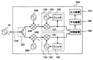
次に、より広い周波数範囲の被測定信号Vに対して位相雑音を測定することができる位相雑音測定装置200を、本発明の第二の実施形態として以下に説明する。ここで、本発明の第二の実施形態である位相雑音測定装置200の構成を示すブロック図を図4に示す。図4において、図1と同一の構成要素には、同一の参照符号を付して、説明を省略する。
Next, a phase
図4において、位相雑音測定装置200は、位相雑音測定装置100に加えて、ミキサ230、信号源240、ミキサ250、および、信号源260を備える。また、位相雑音測定装置200は、分配器120に代えて分配器220を備える。分配器220は、分配器120よりも広帯域な分配器である。信号源240および信号源260の出力信号の周波数は、可変である。ミキサ230と信号源240との組、および、ミキサ250と信号源260との組は、それぞれ周波数変換装置を構成している。信号源240の出力信号の周波数と信号源260の出力信号の周波数とが異なる場合、ミキサ230の出力信号である中間信号V1とミキサ250の出力信号である中間信号V2は、周波数が異なる。その場合、信号源133および信号源143には、それぞれ異なる周波数が設定される。なお、信号源240および信号源260の出力信号の周波数は、固定であっても良い。ただし、その場合は、測定周波数範囲が制限される。
In FIG. 4, the phase
一般な手法に従って周波数変換を行う場合、被測定信号Vは分配器220の前段で周波数変換される。しかし、本実施形態では、分配器220の後段で、それぞれ独立した装置を用いて周波数変換する。このように、位相検出手段の前段で被測定信号の処理を行う場合、分配器と位相検出手段との間のそれぞれの経路に別個の信号処理手段を備えるようにすれば、それらの信号処理手段に起因して生じる位相雑音成分が被測定信号の位相雑音測定結果に及ぼす影響を低減することができる。すなわち、ミキサ230、信号源240、ミキサ250、および、信号源260によって生じる位相雑音成分は、後段の相関装置150において相互相関成分として処理されるので、被測定信号Vの位相雑音測定結果に及ぼす影響を低減することができる。
When frequency conversion is performed according to a general method, the signal under measurement V is frequency converted before the
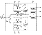
次に、より広い周波数範囲の被測定信号Vに対して位相雑音を測定することができる位相雑音測定システムを、本発明の第三の実施形態として以下に説明する。ここで、本発明の第三の実施形態である位相雑音測定システム1000の構成を示すブロック図を図5に示す。なお、図5において、図4と同一の構成要素には、同一の参照符号を付して、説明を省略する。以下、図5を参照する。位相雑音測定システム1000は、位相雑音測定装置300と周波数変換ボックス20とを備える。
Next, a phase noise measurement system capable of measuring phase noise with respect to a signal under measurement V in a wider frequency range will be described below as a third embodiment of the present invention. Here, FIG. 5 shows a block diagram showing the configuration of the phase
位相雑音測定装置300は、位相雑音測定装置200において、ミキサ230、信号源240、ミキサ250、および、信号源260が除去され、入力端子310、入力端子340、および、入力端子360、ならびに、出力端子330、および、出力端子350が追加されたものである。入力端子310は、被測定信号Vを受信するための端子であり、受信した信号を分配器220に供給する。出力端子330および出力端子350は、分配器220に接続されている。分配器220は、入力端子310において受信した被測定信号Vを分配して、出力端子330と出力端子350とに、それぞれ出力する。入力端子340は、中間信号V1を受信するための端子であり、受信した信号をPLLブロック130に供給する。入力端子360は、中間信号V2を受信するための端子であり、受信した信号をPLLブロック140に供給する。なお、中間信号V1は、分配器220により被測定信号Vから分配された信号、または、分配後さらにミキサ230と信号源240とにより周波数変換された信号である。また、中間信号V2は、分配器120により被測定信号Vから分配された信号、または、分配後さらにミキサ250およびと信号源260とにより周波数変換された信号である。
In the phase
周波数変換ボックス20は、入力端子21および23と、出力端子22および24と、信号源240および260と、ミキサ230および250とを備える。入力端子21は、出力端子330と接続されている。また、入力端子23は、出力端子350と接続されている。さらに、出力端子22は、入力端子340と接続されている。またさらに、出力端子24は、入力端子360と接続されている。周波数変換ボックス20において、入力端子21で受信される信号は、信号源240が接続されたミキサ230により周波数変換されて、出力端子22より出力される。また、入力端子23で受信される信号は、信号源260が接続されたミキサ250により周波数変換されて、出力端子24より出力される。なお、周波数変換ボックス20は、位相雑音測定装置300もしくはPCなどの外部制御装置からの制御情報を受信するためのコネクタ端子(不図示)を備える。また、信号源240および信号源260の出力信号の周波数は、位相雑音測定装置300により制御される。
The
以上に説明したように、分配器220とPLLブロック130との間の接続経路は、出力端子330と入力端子340との対によりテストオペレータに開放される。また、分配器220とPLLブロック140との間の接続経路は、出力端子350と入力端子360との対によりテストオペレータに開放される。周波数変換が不要である場合、出力端子330と入力端子340との間、および、出力端子350と入力端子360との間を、それぞれ短絡すれば良い。また、周波数変換が必要である場合、出力端子330を入力端子21に、出力端子22を入力端子340に、出力端子350を入力端子23に、出力端子24を入力端子360に、それぞれ接続すれば良い。位相雑音測定システム1000において、位相雑音測定装置200と同様に、分配器と位相検出手段との間のそれぞれの経路に別個の信号処理手段を備えられるようにしているので、それらの信号処理手段に起因して生じる位相雑音成分が被測定信号の位相雑音測定結果に及ぼす影響を低減することができる。また、位相雑音測定システム1000は、周波数変換を選択的に実施できる。さらに、位相雑音測定装置300は、一旦、被測定信号Vを受信するので、被測定信号Vの別のパラメータを測定する装置を内蔵することが容易である。
As described above, the connection path between the
次に、より広い周波数範囲の被測定信号Vに対して位相雑音を測定することができる他の位相雑音測定システムを、本発明の第四の実施形態として以下に説明する。ここで、本発明の第四の実施形態である位相雑音測定システム2000の構成を示すブロック図を図6に示す。図6において、図5と同一の構成要素には、同一の参照符号を付して、説明を省略する。以下、図6を参照する。位相雑音測定システム2000は、周波数変換ボックス20と、位相雑音測定装置400とを備える。
Next, another phase noise measurement system capable of measuring phase noise for a signal under measurement V in a wider frequency range will be described below as a fourth embodiment of the present invention. Here, FIG. 6 shows a block diagram showing a configuration of a phase
図6において、位相雑音測定装置400は、位相雑音測定装置200において、さらに、スイッチ410、スイッチ420、スイッチ430、および、スイッチ440が追加された装置である。分配器220は、出力端子330および出力端子350の代わりに、スイッチ410とスイッチ430とに接続される。また、出力端子330は、スイッチ410に接続される。さらに、出力端子350は、スイッチ430に接続される。PLLブロック130は、入力端子340の代わりにスイッチ420に接続される。また、PLLブロック140は、入力端子360の代わりにスイッチ440に接続される。さらに、入力端子340は、スイッチ420に接続される。またさらに、入力端子360は、スイッチ440に接続される。スイッチ410は、分配器120の出力信号の1つを出力端子330またはスイッチ420に供給する。スイッチ420は、入力端子340からの信号またはスイッチ410からの信号をPLLブロック130に供給する。スイッチ430は、分配器120の出力信号の他の1つを出力端子350またはスイッチ440に供給する。スイッチ440は、入力端子360からの信号またはスイッチ430からの信号をPLLブロック140に供給する。
In FIG. 6, the phase
被測定信号Vが比較的低周波である場合、スイッチ410はa1側を選択し、スイッチ420はb1側を選択し、スイッチ430はc1側を選択し、スイッチ440はd1側を選択する。そして、分配器120の出力信号のそれぞれは、そのままPLLブロック130とPLLブロック140とに供給される。一方、被測定信号Vが比較的高周波である場合、スイッチ410はa2側を選択し、スイッチ420はb2側を選択し、スイッチ430はc2側を選択し、スイッチ440はd2側を選択する。そして、分配器120の出力信号のそれぞれは、別個に周波数変換された後にPLLブロック130およびPLLブロック140へ供給される。位相雑音測定システム2000は、以上のように構成されるので、位相雑音測定システム1000に比べて、測定周波数範囲の選択に伴う端子接続の煩わしさを軽減することができる。
When the signal under measurement V has a relatively low frequency, the
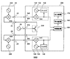
次に、より広い周波数範囲の被測定信号Vに対して位相雑音を測定することができる他の位相雑音測定システムを、本発明の第五の実施形態を以下に説明する。ここで、本発明の第五の実施形態である位相雑音測定システム3000の構成を示すブロック図を図7に示す。図7において、図5と同一の構成要素には、同一の参照符号を付して、説明を省略する。以下、図7を参照する。位相雑音測定システム3000は、周波数変換ボックス30と、位相雑音測定装置500とを備える。
Next, another phase noise measurement system capable of measuring phase noise for a signal under measurement V in a wider frequency range will be described below with reference to a fifth embodiment of the present invention. FIG. 7 is a block diagram showing the configuration of the phase
位相雑音測定装置500は、位相雑音測定装置300において、分配器220の代わりに分配器120を備えたものである。分配器120は、図1に示される分配器と同じものであり、分配器220よりも比較的狭帯域である。
The phase
周波数変換ボックス30は、入力端子31と、分配器220と、信号源240および260と、ミキサ230および250と、スイッチ32および33と、出力端子34および35とを備える。入力端子31は、被測定信号Vを受信するための端子である。分配器220は、入力端子31において受信した被測定信号Vを分配して、スイッチ32とスイッチ33とに供給する装置である。スイッチ32は、分配された信号をミキサ230または出力端子34に供給する。スイッチ33は、分配された信号をミキサ250または出力端子35に供給する。ミキサ230は、信号源240が接続されている。また、ミキサ230は、スイッチ32の出力信号を周波数変換して、出力端子34へ出力する。ミキサ250は、信号源260が接続されている。また、ミキサ250は、スイッチ33の出力信号を周波数変換して、出力端子35へ出力する。出力端子34は、入力端子340に接続されている。また、出力端子35は、入力端子360に接続されている。
The
被測定信号Vが比較的低周波である場合、スイッチ32はe1側を選択し、スイッチ33はf1側を選択する。さらに、信号源240および信号源260からは、直流信号が出力される。この時、分配器220の出力信号は、そのまま位相雑音測定装置500へ供給される。一方、被測定信号Vが比較的高周波である場合、スイッチ32はe2側を選択し、スイッチ33はf2側を選択し、分配器220の出力信号は周波数変換されてから位相雑音測定装置500へ供給される。なお、周波数変換ボックス30は、位相雑音測定装置500もしくはPCなどの外部制御装置からの制御情報を受信するためのコネクタ端子(不図示)を備える。また、信号源240および信号源260の出力信号の周波数は、位相雑音測定装置300により制御される。さらに、スイッチ32および33の選択状態は、位相雑音測定装置500により制御される。位相雑音測定システム3000は、以上のように構成されるので、測定周波数範囲の選択に伴う端子接続の煩わしさを軽減することができる。
When the signal under measurement V has a relatively low frequency, the
次に、より広い周波数範囲の被測定信号Vに対して位相雑音を測定することができる他の位相雑音測定システムを、本発明の第六の実施形態を以下に説明する。ここで、本発明の第六の実施形態である位相雑音測定システム4000の構成を示すブロック図を図8に示す。図8において、図7と同一の構成要素には、同一の参照符号を付して、説明を省略する。以下、図8を参照する。位相雑音測定システム4000は、周波数変換ボックス40と、位相雑音測定装置600とを備える。
Next, another phase noise measurement system capable of measuring phase noise for a signal under measurement V in a wider frequency range will be described below with reference to a sixth embodiment of the present invention. FIG. 8 is a block diagram showing the configuration of the phase
位相雑音測定装置600は、位相雑音測定装置500に比べて、出力端子330および350が除去され、スイッチ610および620が追加されている。分配器120は、スイッチ610とスイッチ620とに接続される。分配器120は、入力端子310において受信した被測定信号Vを分配し、分配された信号のそれぞれは、スイッチ610とスイッチ620とに供給される。PLLブロック130は、入力端子340の代わりにスイッチ610に接続される。また、入力端子340は、スイッチ610と接続される。PLLブロック140は、入力端子360の代わりにスイッチ620に接続される。また、入力端子360は、スイッチ620と接続される。
Compared with the phase
周波数変換ボックス40は、入力端子41と、分配器42と、信号源240および260と、ミキサ230および250とを備える。入力端子41は、被測定信号Vを受信するための端子である。分配器42は、入力端子41において受信した被測定信号Vを分配して、ミキサ230とミキサ250とに供給する装置である。ミキサ230は、信号源240が接続されている。また、ミキサ230は、分配器42により分配された信号の1つを周波数変換して、出力端子43へ出力する。ミキサ250は、信号源260が接続されている。また、ミキサ250は、分配器42により分配された信号の他の1つを周波数変換して、出力端子44へ出力する。出力端子43は、入力端子340に接続されている。また、出力端子44は、入力端子360に接続されている。
The
被測定信号Vが比較的低周波である場合、被測定物10は、入力端子310に接続される。さらに、位相雑音測定装置600において、スイッチ610はx1側を選択し、スイッチ620はy1側を選択する。この時、分配器120の出力信号の1つは、スイッチ610を経由してPLLブロック130に供給される。また、分配器120の出力信号の他の1つは、スイッチ620を経由してPLLブロック140に供給される。一方、被測定信号Vが比較的高周波である場合、被測定物10は、入力端子41に接続される。さらに、位相雑音測定装置500において、スイッチ610はx2側を選択し、スイッチ620はy2側を選択する。この時、出力端子43から出力される信号は、スイッチ610を経由してPLLブロック130に供給される。また、出力端子44から出力される信号は、スイッチ620を経由してPLLブロック140に供給される。なお、周波数変換ボックス40は、位相雑音測定装置600もしくはPCなどの外部制御装置からの制御情報を受信するためのコネクタ端子(不図示)を備える。また、信号源240および信号源260の出力信号の周波数は、位相雑音測定装置300により制御される。位相雑音測定装置600は、以上のように構成されるので、測定周波数範囲が変更される場合であっても、周波数変換ボックス40を着脱する必要がない。
When the signal under measurement V has a relatively low frequency, the device under
ところで、これまでに説明した実施形態において、信号源133や信号源143は、被測定信号Vの周波数に応じて、出力信号の周波数を細かく設定することができる。一般に、そのような信号源は、所望の周波数fLO以外に、次式で表される周波数fSUPRを有するスプリアスを生じる。
By the way, in the embodiment described so far, the
ただし、iおよびjは、1以上の整数である。fLOは、信号源の出力信号の周波数である。また、frefは、該信号源の基準信号周波数である。 However, i and j are integers of 1 or more. f LO is the frequency of the output signal of the signal source. F ref is the reference signal frequency of the signal source.
このスプリアスは、被測定信号Vの位相雑音の測定結果に影響を及ぼす場合がある。例えば、周波数fSUPRが、周波数fLOに近い場合に、そのスプリアスが被測定信号Vの位相雑音として測定されてしまうのである。そこで、そのようなスプリアスの影響をなくすようにした位相雑音測定装置を、本発明の第六の実施形態として、以下に説明する。 This spurious may affect the measurement result of the phase noise of the signal under measurement V. For example, when the frequency f SUPR is close to the frequency f LO , the spurious is measured as the phase noise of the signal under measurement V. Therefore, a phase noise measuring apparatus that eliminates the influence of such spurious will be described below as a sixth embodiment of the present invention.
本発明の第七の実施形態である位相雑音測定装置700の構成を示すブロック図を図9に示す。図9において、図1と同一の構成要素には、同一の参照符号を付して、説明を省略する。図9において、位相雑音測定装置700は、図1に示す位相雑音測定装置100において、PLLブロック130をPLLブロック710に、PLLブロック140をPLLブロック730に、それぞれ置き換えたものである。PLLブロック710は、PLLブロック130において、信号源133を信号源720に置き換えたものである。PLLブロック730は、PLLブロック140において、信号源143を信号源740に置き換えたものである。
FIG. 9 is a block diagram showing the configuration of the phase
信号源720は、基準信号源721とシンセサイザ722とを備える。シンセサイザ722は、基準信号源721の出力信号を参照して局部信号を発生し出力する。シンセサイザ722の出力信号の周波数および位相は、フィルタ132の出力信号により制御される。また、信号源740は、基準信号源741とシンセサイザ742とを備える。シンセサイザ742は、基準信号源741の出力信号を参照して局部信号を発生し出力する。シンセサイザ742の出力信号の周波数および位相は、フィルタ142の出力信号により制御される。シンセサイザ722の出力信号の周波数fLO1とシンセサイザ742の出力信号の周波数fLO2は、同一である。一方、基準信号源721の出力信号の周波数fref1と基準信号源741の出力信号の周波数fref2は、異なる。この時、シンセサイザ722から出力されるスプリアスの周波数をfSUPR1とし、シンセサイザ742から出力されるスプリアスの周波数をfSUPR2とすると、fSUPR1≠fSUPR2、となる。これらのスプリアスは、後段の相関装置150において、それぞれが独立成分として扱われるので、クロススペクトラムの平均化処理とにより、ゼロに近づく。このようなスプリアスの低減効果は、巨視的には、周波数fref1と周波数fref2とが離れるにつれて大きくなる。また、周波数fref1と周波数fref2は、所定の周波数fdiff以上離れていることが望ましい。なお、周波数fdiffは、1回のクロススペクトラム処理が対象とする時間(観測時間)の逆数である。例えば、相関装置150において、32kHzでアナログ・ディジタル変換した結果に対して1024ポイントのFFT処理を実施する場合、1回の観測時間は、32ミリ秒である。従って、この場合の周波数fdiffは、31.25Hzとなる。もちろん、周波数fref1と周波数fref2とが所定の周波数fdiff以上離れていない場合であっても、スプリアス低減の効果が全くない訳ではない。周波数fref1と周波数fref2とをどの程度離すかは、要求されるスプリアス低減率に依存する。なお、上記のスプリアス低減技術は、他の実施形態の位相雑音測定装置に対しても適用することができる。例えば、位相雑音測定装置200において、信号源133および信号源143それぞれの基準信号源の周波数が互いに異なるようにすれば良い。この場合、信号源133の出力信号の周波数と信号源143の出力信号の周波数は、同じである必要はない。また、位相雑音測定装置200において、信号源240、信号源260、信号源133および信号源143それぞれの基準信号源の周波数が互いに異なるようにすると、なお良い。
The
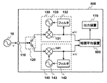
ところで、スペクトラムの全帯域を高い周波数分解能で演算しようとした場合、膨大な測定資源を要する。次に、そのような問題を解決する位相雑音測定装置を、本発明の第八の実施形態として以下に説明する。ここで、図10を参照する。図10は、本発明の第八の実施形態である位相雑音測定装置800を示す図である。図10において、図1と同一の構成要素には、同一の参照符号を付して、説明を省略する。
By the way, when trying to calculate the entire spectrum band with high frequency resolution, a huge amount of measurement resources are required. Next, a phase noise measuring apparatus for solving such a problem will be described below as an eighth embodiment of the present invention. Reference is now made to FIG. FIG. 10 is a diagram showing a phase
図10において、位相雑音測定装置800は、入力端子110と、分配器120と、PLLブロック130と、PLLブロック140と、相関平均装置900と、出力装置170とを備える。相関平均装置900は、PLLブロック130の出力信号である位相信号a(t)とPLLブロック140の出力信号である位相信号b(t)とのクロススペクトラムを求める。相関平均装置900は、さらに、求めたクロススペクトラムの結果を平均化する。
In FIG. 10, the phase
ここで、図11を参照して、相関平均装置900について詳述する。図11は、相関平均装置900の構成を示す図である。図11において、相関平均装置900は、ADC910aと、ADC910bと、相関処理ブロック920と、相関処理ブロック930と、フィルタ931aと、フィルタ931bと、相関処理ブロック940と、フィルタ941aと、フィルタ941bと、平均器950とを備える。ADC910aは、位相信号a(t)をアナログ・ディジタル変換する装置である。ADC910bは、位相信号b(t)をアナログ・ディジタル変換する装置である。ADC910aおよびADC910bは、同一の変換処理速度fs(サンプル/秒)を有する。ADC910aの変換結果である位相信号a1(t)とADC910bの変換結果である位相信号b1(t)は、相関処理ブロック920に入力される。フィルタ931a、フィルタ931b、フィルタ941aおよびフィルタ941bは、1/8デシメーションフィルタである。フィルタ931aは、位相信号a1(t)の帯域とレートを1/8にする。フィルタ931bは、位相信号b1(t)の帯域とレートを1/8にする。フィルタ941aは、フィルタ931aの出力である位相信号a2(t)の帯域とレートを1/8にする。フィルタ941bは、フィルタ931bの出力である位相信号b2(t)の帯域とレートを1/8にする。
Here, the
相関処理ブロック920は、位相信号a1(t)と位相信号b1(t)とのクロススペクトラムを生成する装置である。相関処理ブロック920は、メモリ922aと、メモリ922bと、FFT923aと、FFT923bと、乗算器924と、平均器925とを備える。メモリ922aは、位相信号a1(t)を格納する装置である。FFT923aは、メモリ922aに格納された位相信号a1(t)をフーリエ変換する。そして、位相信号a1(t)のフーリエ変換結果のうち、ナイキスト周波数(fs/2)以下の成分A1(f)が乗算器924に出力される。メモリ922bは、位相信号b1(t)を格納する装置である。FFT923bは、メモリ922bに格納された位相信号b1(t)をフーリエ変換する。そして、位相信号b1(t)のフーリエ変換結果のうち、ナイキスト周波数(fs/2)以下の成分B1(f)が乗算器924に出力される。なお、FFT923aおよびFFT923bは、同一のポイント数を有する。乗算器924は、フーリエ変換結果A1(f)とフーリエ変換結果B1(f)とについて次式で表される処理を施す。
The
なお、S1ab(f)は、a1(t)とb1(t)とのクロススペクトラムである。また、上付き添え字*は、複素共役を表す。 S1ab (f) is a cross spectrum between a1 (t) and b1 (t). The superscript * indicates a complex conjugate.
乗算器924の処理結果であるS1ab(f)は、平均器925へ出力される。平均器925は、処理結果S1ab(f)に対して次式で表される時間方向のベクトル平均処理を施す。
S1 ab (f), which is the processing result of the
なお、S1ab(k,f)は、k番目に得られるクロススペクトラムS1ab(f)である。 Note that S1 ab (k, f) is the k-th obtained cross spectrum S1 ab (f).
平均器925の処理結果である平均化クロススペクトラムAS1ab(f)は平均器950へ出力される。
The averaged cross spectrum AS1 ab (f), which is the processing result of the
相関処理ブロック930は、位相信号a2(t)と位相信号b2(t)とのクロススペクトラムを生成する装置である。相関処理ブロック930は、メモリ932aと、メモリ932bと、FFT933aと、FFT933bと、乗算器934と、平均器935とを備える。メモリ932aは、位相信号a2(t)を格納する装置である。FFT933aは、メモリ932aに格納された位相信号a2(t)をフーリエ変換する。そして、位相信号a2(t)のフーリエ変換結果のうち、ナイキスト周波数(fs/16)以下の成分A2(f)が乗算器934に出力される。メモリ932bは、位相信号b2(t)を格納する装置である。FFT933bは、メモリ932bに格納された位相信号b2(t)をフーリエ変換する。そして、位相信号b2(t)のフーリエ変換結果のうち、ナイキスト周波数(fs/16)以下の成分B2(f)が乗算器934に出力される。なお、FFT923aおよびFFT933bは、同一のポイント数を有する。乗算器934は、フーリエ変換結果A2(f)とフーリエ変換結果B2(f)とについて次式で表される処理を施す。
The
なお、S2ab(f)は、a2(t)とb2(t)とのクロススペクトラムである。また、上付き添え字*は、複素共役を表す。 S2ab (f) is a cross spectrum between a2 (t) and b2 (t). The superscript * indicates a complex conjugate.
乗算器934の処理結果であるS2ab(f)は、平均器935へ出力される。平均器935は、処理結果S2ab(f)に対して次式で表される時間方向のベクトル平均処理を施す。
S2 ab (f), which is the processing result of the
なお、S2ab(k,f)は、k番目に得られるクロススペクトラムS2ab(f)である。 Note that S2 ab (k, f) is the k-th obtained cross spectrum S2 ab (f).
平均器935の処理結果である平均化クロススペクトラムAS2ab(f)は平均器950へ出力される。
The averaged cross spectrum AS2 ab (f), which is the processing result of the
相関処理ブロック940は、フィルタ941aの出力である位相信号a3(t)とフィルタ941bの出力である位相信号b3(t)とのクロススペクトラムを生成する装置である。相関処理ブロック940は、メモリ942aと、メモリ942bと、FFT943aと、FFT943bと、乗算器944とを備える。メモリ942aは、位相信号a3(t)を格納する装置である。FFT943aは、メモリ942aに格納された位相信号a3(t)をフーリエ変換する。そして、位相信号a3(t)のフーリエ変換結果のうち、ナイキスト周波数(fs/128)以下の成分A3(f)が乗算器944に出力される。メモリ942bは、位相信号b3(t)を格納する装置である。FFT943bは、メモリ942bに格納された位相信号b3(t)をフーリエ変換する。そして、位相信号b3(t)のフーリエ変換結果のうち、ナイキスト周波数(fs/128)以下の成分B3(f)が乗算器944に出力される。なお、FFT923aおよびFFT943bは、同一のポイント数を有する。乗算器944は、フーリエ変換結果A3(f)とフーリエ変換結果B3(f)とについて次式で表される処理を施す。
The correlation processing block 940 is a device that generates a cross spectrum between the phase signal a3 (t) that is the output of the filter 941a and the phase signal b3 (t) that is the output of the filter 941b. The correlation processing block 940 includes a
なお、S3ab(f)は、a3(t)とb3(t)とのクロススペクトラムである。また、上付き添え字*は、複素共役を表す。 S3 ab (f) is a cross spectrum between a3 (t) and b3 (t). The superscript * indicates a complex conjugate.
乗算器944の処理結果であるS3ab(f)は、平均器950へ出力される。
S3 ab (f), which is the processing result of the
念のため述べておくと、S3ab(f)が1つ得られる間に、S2ab(f)は8つ得られ、S1ab(f)は64個得られる。8個のS2ab(f)は、平均されて1つのAS2ab(f)となる。また、64個のS1ab(f)は、平均されて1つのAS1ab(f)となる。 To be sure, while one S3 ab (f) is obtained, eight S2 ab (f) are obtained and 64 S1 ab (f) are obtained. Eight S2 ab (f) is an average has been one AS2 ab (f). Further, 64 S1 ab (f) are averaged to become one AS1 ab (f).
さて、各相関処理ブロックの処理結果AS1ab(f)、AS2ab(f)およびS3ab(f)は、線形に等間隔な周波数に対応するものである。しかし、位相雑音の測定結果において、少なくとも周波数軸はログスケールで表示される。従って、処理結果AS1ab(f)、AS2ab(f)およびS3ab(f)を、対数的に等間隔な周波数に対応させる必要がある。そこで、平均器950は、各相関処理ブロックの処理結果AS1ab(f)、AS2ab(f)およびS3ab(f)を組み合わせて、対数的に等間隔な周波数に対応する1つのクロススペクトラムを生成する。以下に、その手順の一例を説明する。
The processing results AS1 ab (f), AS2 ab (f), and S3 ab (f) of each correlation processing block correspond to linearly spaced frequencies. However, in the measurement result of phase noise, at least the frequency axis is displayed on a log scale. Therefore, the processing results AS1 ab (f), AS2 ab (f), and S3 ab (f) need to correspond to logarithmically spaced frequencies. Therefore, the
まず、ADC910aおよびADC910bの変換速度は、100Mサンプル/秒とする。各相関処理ブロックにおけるFFTのポイント数は、128ポイントとする。この時、相関処理ブロック920におけるFFT点は、表4に示される通りである。また、相関処理ブロック930におけるFFT点は、表5に示される通りである。さらに、相関処理ブロック940におけるFFT点は、表6に示される通りである。なお、それらの表には、ナイキスト周波数以下の点のみが、対応する周波数とともに表示されている。
First, the conversion speed of the ADC 910a and the ADC 910b is 100 Msample / second. The number of FFT points in each correlation processing block is 128 points. At this time, the FFT points in the
次に、表4、表5および表6のそれぞれに示される線形的に等間隔な周波数に対応するクロススペクトラムを、表7に示されるような対数的に等間隔な周波数に対応させる。なお、クロススペクトラムは、100kHzから45MHzの間の対数的に等間隔な51の周波数点で表示されるものとする。 Next, the cross spectrum corresponding to the linearly equidistant frequency shown in Table 4, Table 5, and Table 6 is made to correspond to the logarithmically equidistant frequency shown in Table 7. The cross spectrum is displayed at 51 frequency points that are logarithmically spaced between 100 kHz and 45 MHz.
表7には、表示点と対応する周波数が示されている。また、隣接する表示点間の中点に対応する周波数が、境界周波数として示されている。本手順では、各表示点の両側の境界周波数の参照し、それらの境界周波数間にある線形的に等間隔な周波数点を選ぶ。そして、選んだ周波数点に対応するクロススペクトラムをベクトル平均する。最後に、ベクトル平均結果を対数的に等間隔な表示点のクロススペクトラムとする。 Table 7 shows the frequencies corresponding to the display points. Further, the frequency corresponding to the midpoint between adjacent display points is shown as the boundary frequency. In this procedure, reference is made to the boundary frequencies on both sides of each display point, and linearly equidistant frequency points between those boundary frequencies are selected. Then, the cross spectrum corresponding to the selected frequency point is vector averaged. Finally, the vector average result is a cross spectrum of display points that are logarithmically spaced.
例えば、カウント8の表示点のクロススペクトラムは、以下のとおりに得られる。まず、カウント8の表示点の両側の境界周波数を参照する。つまり、250024Hzと282518Hzである。次に、その2つの周波数間に含まれるFFT点を表4、表5または表6から探す。できるだけ多くのFFT点を見つけるために、周波数間隔が小さい表から順に探す。つまり、表6、表5、表4の順に該当するFFT点を探す。そうすると、相関処理ブロック940に関する表6において、カウント21からカウント23のFFT点が見つかる。次に、見つかった3つのFFT点におけるクロススペクトラムのベクトル平均を求める。平均により得られた1つのクロススペクトラムがカウント8の表示点のクロススペクトラムである。また、カウント17の表示点のクロススペクトラムは、以下のとおりに得られる。カウント17の表示点の両側の境界周波数は、750862Hzと848446Hzである。表6において、カウント62からカウント64の表示点が見つかる。750862Hzと848446Hzとの間には、さらに、表6に示されていないナイキスト周波数を超える周波数成分(793457Hz,805664Hz,817871Hz,830078Hz,842285Hz)も含まれる。そのような成分をベクトル平均することは、測定結果に誤差を生じさせる要因となるので、許容されない。そこで、相関処理ブロック930に関する表5から、同様にFFT点を探す。そうすると、表5において、カウント8のFFT点が見つかる。FFT点が1つの場合、元の値も平均値も同じである。従って、カウント8のFFT点におけるクロススペクトラムを、そのままカウント17の表示点のクロススペクトラムとする。表7には、以上のように関連づけられるFFT点の始点と終点とそれらに関連する相関処理ブロックが示されている。
For example, the cross spectrum of the display point of count 8 is obtained as follows. First, reference is made to the boundary frequencies on both sides of the display point of count 8. That is, they are 250024 Hz and 282518 Hz. Next, the FFT point included between the two frequencies is searched from Table 4, Table 5, or Table 6. In order to find as many FFT points as possible, the table is searched in order from the table with the smallest frequency interval. That is, the corresponding FFT points are searched in the order of Table 6, Table 5, and Table 4. Then, in Table 6 regarding the correlation processing block 940, the FFT points of the
見つかったFFT点が2以上ある場合、クロススペクトラムの周波数方向のベクトル平均処理がなされる。その平均対象数が多いほど、信号源133で発生する位相雑音成分や信号源143で発生する位相雑音成分がゼロに近づく。
When two or more FFT points are found, vector averaging processing in the frequency direction of the cross spectrum is performed. As the average number of objects increases, the phase noise component generated at the
以上に例示した方法は、線形的に等間隔な周波数に対応する該スペクトラムから、対数的に等間隔な周波数から所定の周波数範囲に含まれる該スペクトラムを選択し、選択したスペクトラムに対してベクトル平均を施している。線形的に等間隔な周波数に対応するクロススペクトラムを、対数的に等間隔な周波数に対応させる他の方法としては、線形的に等間隔な周波数に対応する該スペクトラムに対して、周波数が高くなるにつれて平均対象を対数的に増加させながら周波数方向のベクトル平均を施す方法もある。なお、実際には、計算精度の不足などにより、各周波数点を完全に等間隔に配置することが難しい場合がある。その場合、各周波数点は、おおよそ等間隔に配置されていれば良い。 The method exemplified above selects the spectrum included in the predetermined frequency range from the logarithmically spaced frequency from the spectrum corresponding to the linearly spaced frequency, and performs vector averaging on the selected spectrum. Has been given. As another method of making the cross spectrum corresponding to linearly equidistant frequencies correspond to logarithmically equidistant frequencies, the frequency becomes higher than the spectrum corresponding to linearly equidistant frequencies. There is also a method of performing vector averaging in the frequency direction while increasing the average object logarithmically. Actually, it may be difficult to completely arrange the frequency points at equal intervals due to lack of calculation accuracy. In that case, each frequency point should just be arrange | positioned at equal intervals.
さて、以上に説明した周波数方向のベクトル平均により、処理結果AS1ab(f)、AS2ab(f)およびS3ab(f)から得られる1つのクロススペクトラムをSWab(f)とする。相関平均装置900は、クロススペクトラムSWab(f)を所定の数だけ求める。また、平均器950は、クロススペクトラムSWab(f)に対して次式で表される時間方向のベクトル平均処理を施す。
Now, let SW ab (f) be one cross spectrum obtained from the processing results AS1 ab (f), AS2 ab (f), and S3 ab (f) by the vector average in the frequency direction described above.
なお、Nは、1以上の整数である。SWab(k,f)は、k番目に得られたクロススペクトラムSWab(f)である。この時、平均の対象であるクロススペクトラムの数Nが多いほど、信号源133で発生する位相雑音成分や信号源143で発生する位相雑音成分を一層ゼロに近づけることができる。
N is an integer of 1 or more. SW ab (k, f) is the k-th obtained cross spectrum SW ab (f). At this time, as the number N of cross spectrums to be averaged increases, the phase noise component generated at the
次に、平均化の効果を表すグラフを図12に示す。図12は、全く位相雑音を含まない理想的な被測定信号Vが位相雑音測定装置800に入力される時のクロススペクトラムを両対数グラフに表示させたものである。図12に示すグラフの縦軸は電力であり、横軸はオフセット周波数である。図12に示される線は、いわゆるノイズフロアである。図12において、線Aと線Bは、図3に示したものである。なお、実際の線Aは、水平線ではなく、周波数が高くなるにつれてなだらかに降下する曲線を描く。しかし、本明細書では、説明を簡単にするために、線Aを水平線と仮定する。また、線Eおよび線Fは、線Aに対する差分が表現されている。さて、線Eは、相関平均装置900において、周波数方向のベクトル平均を実施しないクロススペクトラムを複数回求め、得られた複数のクロススペクトラムを時間方向でベクトル平均した時のクロススペクトラムである。線Eは、平均器925および平均器935の平均効果により階段状になっている。また、線Fは、周波数方向のベクトル平均が施されたクロススペクトラムSWab(f)を複数回求め、得られた複数のクロススペクトラムに時間方向のベクトル平均を施した時のクロススペクトラムである。線Fは、オフセット周波数が高くなるにつれて、なだらかに下降している。一般に、位相雑音は、オフセット周波数が高くなるにつれて小さくなるので、線Fのような形状は好ましい。
Next, a graph showing the effect of averaging is shown in FIG. FIG. 12 shows a double logarithmic graph showing a cross spectrum when an ideal signal under measurement V including no phase noise is input to the phase
最後に、平均化クロススペクトラムASWab(k,f)は、出力装置170へ出力される。
Finally, the averaged cross spectrum ASW ab (k, f) is output to the
なお、以上に説明した周波数方向のベクトル平均処理は、時間方向のベクトル平均処理の後に行うようにしても良い。その場合、例えば、乗算器944の後に新たに平均器を追加する。そして、該平均器における平均回数をmとする時、平均器935における平均回数を(8・m)とし、平均器925における平均回数を(64・m)とし、平均器950では周波数方向のベクトル平均のみを行うようにすれば良い。
Note that the vector averaging process in the frequency direction described above may be performed after the vector averaging process in the time direction. In this case, for example, a new averager is added after the
本第八の実施形態では、互いに異なる周波数帯域を有する複数の周波数領域のそれぞれにおいて、2つの位相信号のクロススペクトラムを求めるようにしている。すなわち、互いに異なる周波数帯域を有する相関処理ブロック920,930および940は、実質的に周波数帯域を分担して、クロススペクトラムを求めている。これにより、各相関処理ブロックは、過度な演算性能を備える必要がなくなる。例えば、各相関処理ブロックが内蔵するメモリの総量は、周波数帯域を分担しない場合に要するメモリ量と比べて大幅に少ない。また、相関処理ブロック920,930および940は、所定の同一時間内に複数のクロススペクトラムが得られる場合、それぞれにおいて得られた複数のクロススペクトラムに対して時間方向のベクトル平均が施される。これにより、単に測定資源を節約するだけでなく、ノイズフロアを下げるという測定精度の向上が達成される。 In the eighth embodiment, a cross spectrum of two phase signals is obtained in each of a plurality of frequency regions having different frequency bands. That is, the correlation processing blocks 920, 930 and 940 having different frequency bands substantially share the frequency band to obtain the cross spectrum. This eliminates the need for each correlation processing block to have excessive computing performance. For example, the total amount of memory built in each correlation processing block is significantly smaller than the amount of memory required when not sharing the frequency band. Further, when a plurality of cross spectra are obtained within a predetermined same time, the correlation processing blocks 920, 930, and 940 perform vector averaging in the time direction on the plurality of cross spectra obtained in each. This achieves an improvement in measurement accuracy that not only saves measurement resources but also lowers the noise floor.
さて、これまでに説明した各実施形態において、以下のような変形が可能である。 Now, in each embodiment described so far, the following modifications are possible.
第八の実施形態において、デシメーション率は、任意に選択することができる。また、それぞれのデシメーション率が同一である必要もない。例えば、ADC910aおよびADC910bの変換速度が同じ場合に、フィルタ931aおよびフィルタ931bならびにフィルタ941aおよびフィルタ941bのデシメーション率を1/4としても良い。また、ADC910aおよびADC910bの変換速度が同じ場合に、フィルタ931aおよびフィルタ931bのデシメーション率を1/4とし、フィルタ941aおよびフィルタ941bのデシメーション率を1/16としても良い。 In the eighth embodiment, the decimation rate can be arbitrarily selected. In addition, the decimation rates do not have to be the same. For example, when the conversion speeds of the ADC 910a and the ADC 910b are the same, the decimation rates of the filter 931a and the filter 931b and the filter 941a and the filter 941b may be set to ¼. Further, when the conversion speeds of the ADC 910a and the ADC 910b are the same, the decimation rate of the filter 931a and the filter 931b may be set to ¼, and the decimation rate of the filter 941a and the filter 941b may be set to 1/16.
また、第八の実施形態において、相関処理ブロックの数は、3つに限定されず、さらに多くても良いし、逆に少なくても良い。 In the eighth embodiment, the number of correlation processing blocks is not limited to three, and may be more or less.
また、上記の実施形態のそれぞれにおいて、FFTのポイント数は、任意に選択することができる。また、乗算器に接続される2つのFFTのポイント数は、該乗算器での処理に不都合が生じない限り、同一である必要もない。 In each of the above embodiments, the number of FFT points can be arbitrarily selected. Further, the number of points of the two FFTs connected to the multiplier does not need to be the same as long as there is no inconvenience in the processing in the multiplier.
また、上記の実施形態のそれぞれにおいて、ADCの変換速度は、任意に選択することができる。ただし、ADC151aの変換速度とADC151bの変換速度は、同一であることが望ましい。同様に、ADC910aの変換速度とADC910bの変換速度は、同一であることが望ましい。
In each of the above embodiments, the ADC conversion speed can be arbitrarily selected. However, it is desirable that the conversion speed of the
また、上記の実施形態のそれぞれにおいて、分配器は、信号を分配することができれば、図示されるような抵抗器を用いた分配器に限定されない。例えば、導波路を用いた分配器であっても良い。 In each of the above embodiments, the distributor is not limited to a distributor using resistors as shown in the figure as long as the signal can be distributed. For example, a distributor using a waveguide may be used.
また、上記の実施形態のそれぞれにおいて、位相雑音測定装置の構成要素は、実際にハードウェアとして提供されても良いし、ソフトウェアとプロセッサとにより仮想的に提供されても良い。 In each of the above embodiments, the components of the phase noise measuring device may be actually provided as hardware, or may be virtually provided by software and a processor.
また、上記の実施形態のそれぞれにおいて、FFTの代わりに、ウェーブレット変換などの他のスペクトラム解析手段により位相信号のスペクトラムを求めても良い。そして、スペクトラム解析手段により得られるスペクトラムが、線形的に等間隔な周波数に対応している場合、上述した対数的に等間隔な周波数に対応させる処理を該スペクトラムに施せばよい。また、スペクトラム解析手段より得られるスペクトラムが、すでに対数的に等間隔な周波数に対応している場合、必要に応じて周波数方向の単なる加算平均処理を用いることができる。 In each of the above embodiments, the spectrum of the phase signal may be obtained by other spectrum analysis means such as wavelet transform instead of FFT. When the spectrum obtained by the spectrum analysis means corresponds to linearly equidistant frequencies, the above-described processing to correspond to logarithmically equidistant frequencies may be performed on the spectrum. In addition, when the spectrum obtained from the spectrum analysis means already corresponds to logarithmically equidistant frequencies, a simple averaging process in the frequency direction can be used as necessary.
また、上記の実施形態のそれぞれにおいて、相関装置150は、各位相信号をスペクトラム解析して各位相信号のスペクトラムを求め、さらに、それらのクロススペクトラムを求めることにより、各位相信号の相互相関のスペクトラムを得ている。これらの処理に代えて、相関装置150は、入力される2つの位相信号の相互相関を先に求め、求めた相互相関をスペクトラム解析して、クロススペクトラムを生成しても良い。相関処理ブロック920、および、相関処理ブロック930、および、相関処理ブロック940についても同様の変更が可能である。
In each of the above embodiments, the
さて、測定装置において、線形的に等間隔な周波数に対応するクロススペクトラムを、周波数方向のベクトル平均により、対数的に等間隔な周波数に対応させる方法は、位相雑音測定装置のみならず、相関処理またはクロススペクトラム処理を用いる他の測定装置に対しても適用可能である。例えば、上記の方法は、内部雑音が測定結果に及ぼす影響を低減するために相互相関を利用するFFTアナライザに対しても有効である。すなわち、被測定信号を分配して得られた信号のクロススペクトラムに対して、対数的に等間隔な周波数に対応させるために、周波数方向のベクトル平均を施すことも有効である。線形的に等間隔な周波数に対応するスペクトラムから、対数的に等間隔な周波数から所定の周波数範囲に含まれるスペクトラムを選択し、選択したスペクトラムに対してベクトル平均を施す方法についても同様である。また、線形的に等間隔な周波数に対応するスペクトラムに対して、周波数が高くなるにつれて平均対象を対数的に増加させながら周波数方向のベクトル平均を施す方法についても同様である。 Now, in the measurement device, the method of making the cross spectrum corresponding to the linearly equidistant frequency correspond to the logarithmically equidistant frequency by the vector average in the frequency direction is not only the phase noise measurement device but also the correlation processing. Alternatively, the present invention can be applied to other measurement apparatuses using cross spectrum processing. For example, the above method is also effective for an FFT analyzer that uses cross-correlation to reduce the influence of internal noise on the measurement result. That is, it is also effective to perform vector averaging in the frequency direction in order to correspond to logarithmically spaced frequencies with respect to the cross spectrum of the signal obtained by distributing the signal under measurement. The same applies to a method of selecting a spectrum included in a predetermined frequency range from a logarithmically equidistant frequency from a spectrum corresponding to a linearly equidistant frequency and performing vector averaging on the selected spectrum. The same applies to the method of performing vector averaging in the frequency direction while increasing the number of objects to be averaged logarithmically as the frequency increases with respect to a spectrum corresponding to linearly spaced frequencies.
10 被測定物
20,30,40 周波数変換ボックス
21,23,31,41 入力端子
22,24,34,35,43,44 出力端子
32,33 スイッチ
42 分配器
100,200,300,400,500位相雑音測定装置
600,700,800 位相雑音測定装置
110,310,340,360 入力端子
120,220 分配器
130,140,710,730 PLLブロック
131,141 ミキサ
132,142 フィルタ
133,143,720,740 信号源
150 相関装置
151a,151b アナログ・ディジタル変換器
152a,152b メモリ
153a,153b 高速フーリエ変換器
154 乗算器
160 平均装置
170 出力装置
230,250 ミキサ
240,260 信号源
330,350 出力端子
410,420,430,440,610,620 スイッチ
721,741 基準信号源
722,742 シンセサイザ
900 相関平均装置
920,930,940 相関処理ブロック
922a,922b,932a,932b,942a,942b メモリ
924,934,944 乗算器
925,935 平均器
931a,931b,941a,941b デシメーションフィルタ
950 平均器
1000,2000,3000,4000 位相雑音測定システム
10
Claims (6)
線形的に等間隔な周波数に対応する該スペクトラムから選択した該スペクトラムに対してベクトル平均を施すステップ、
を含むことを特徴とするスペクトラム処理方法。 In a measurement apparatus, a spectrum obtained from a signal under measurement and corresponding to a linearly equidistant frequency is a method of making a logarithmically equidistant frequency correspond to a logarithmically equal frequency,
Applying a vector average to the spectrum selected from the spectrum corresponding to linearly spaced frequencies;
A spectrum processing method comprising:
線形的に等間隔な周波数に対応する該スペクトラムから、対数的に等間隔な周波数から所定の周波数範囲に含まれる該スペクトラムを選択し、選択した該スペクトラムに対してベクトル平均を施すステップ、
を含むことを特徴とするスペクトラム処理方法。 In a measurement apparatus, a spectrum obtained from a signal under measurement and corresponding to a linearly equidistant frequency is a method of making a logarithmically equidistant frequency correspond to a logarithmically equal frequency,
Selecting the spectrum included in a predetermined frequency range from a logarithmically spaced frequency from the spectrum corresponding to linearly spaced frequencies, and performing vector averaging on the selected spectrum;
A spectrum processing method comprising:
線形的に等間隔な周波数に対応する該スペクトラムに対して、周波数が高くなるにつれて平均対象を対数的に増加させながら周波数方向のベクトル平均を施すステップ、
を含むことを特徴とするスペクトラム処理方法。 In a measurement apparatus, a spectrum obtained from a signal under measurement and corresponding to a linearly equidistant frequency is a method of making a logarithmically equidistant frequency correspond to a logarithmically equal frequency,
Performing a vector average in the frequency direction while logarithmically increasing the average object as the frequency increases, with respect to the spectrum corresponding to linearly equally spaced frequencies;
A spectrum processing method comprising:
6. A measuring apparatus for obtaining a cross spectrum obtained from a signal distributed from a signal under measurement and corresponding to a linearly equidistant frequency, wherein the cross spectrum is logarithmized by the method according to claim 5. A measuring apparatus characterized by corresponding to frequency at equal intervals.
Priority Applications (3)
| Application Number | Priority Date | Filing Date | Title |
|---|---|---|---|
| JP2004124969A JP2005308512A (en) | 2004-04-21 | 2004-04-21 | Spectrum processing method and measuring apparatus using the same |
| US11/102,409 US7317999B2 (en) | 2004-04-21 | 2005-04-08 | Method of mapping linearly spaced spectrum points to logarithmically spaced frequency and a measuring apparatus using the method |
| DE102005017545A DE102005017545A1 (en) | 2004-04-21 | 2005-04-16 | A method of mapping linear-distance spectrum spots to a logarithmic-frequency frequency and measuring apparatus using the method |
Applications Claiming Priority (1)
| Application Number | Priority Date | Filing Date | Title |
|---|---|---|---|
| JP2004124969A JP2005308512A (en) | 2004-04-21 | 2004-04-21 | Spectrum processing method and measuring apparatus using the same |
Publications (2)
| Publication Number | Publication Date |
|---|---|
| JP2005308512A true JP2005308512A (en) | 2005-11-04 |
| JP2005308512A5 JP2005308512A5 (en) | 2007-06-14 |
Family
ID=35137566
Family Applications (1)
| Application Number | Title | Priority Date | Filing Date |
|---|---|---|---|
| JP2004124969A Pending JP2005308512A (en) | 2004-04-21 | 2004-04-21 | Spectrum processing method and measuring apparatus using the same |
Country Status (3)
| Country | Link |
|---|---|
| US (1) | US7317999B2 (en) |
| JP (1) | JP2005308512A (en) |
| DE (1) | DE102005017545A1 (en) |
Cited By (1)
| Publication number | Priority date | Publication date | Assignee | Title |
|---|---|---|---|---|
| WO2024053724A1 (en) * | 2022-09-09 | 2024-03-14 | 国立大学法人東京大学 | Signal processing device, signal processing method, and program |
Families Citing this family (5)
| Publication number | Priority date | Publication date | Assignee | Title |
|---|---|---|---|---|
| DE102007010649B8 (en) * | 2007-03-02 | 2009-01-22 | Thermosensorik Gmbh | Method and apparatus for adaptively changing the integration time of an infrared sensor |
| JP2008262021A (en) * | 2007-04-12 | 2008-10-30 | Hiromi Murakami | Phase switching device in electric musical instrument |
| US8639506B2 (en) * | 2010-03-11 | 2014-01-28 | Telefonica, S.A. | Fast partial pattern matching system and method |
| US9651646B2 (en) * | 2014-06-24 | 2017-05-16 | Tektronix, Inc. | Phase noise correction system for discrete time signal processing |
| US11255893B2 (en) | 2018-08-22 | 2022-02-22 | Keysight Technologies, Inc. | Measuring error in signal under test (SUT) using multiple channel measurement device |
Family Cites Families (7)
| Publication number | Priority date | Publication date | Assignee | Title |
|---|---|---|---|---|
| DE3148735A1 (en) | 1981-12-09 | 1986-10-09 | Fried. Krupp Gmbh, 4300 Essen | Method and device for frequency analysis |
| US5051916A (en) * | 1990-01-12 | 1991-09-24 | Tektronix, Inc. | Stimulus signal generation method to maximize dynamic range in frequency response function calculations |
| US5224170A (en) * | 1991-04-15 | 1993-06-29 | Hewlett-Packard Company | Time domain compensation for transducer mismatch |
| US5583961A (en) * | 1993-03-25 | 1996-12-10 | British Telecommunications Public Limited Company | Speaker recognition using spectral coefficients normalized with respect to unequal frequency bands |
| DE4316297C1 (en) | 1993-05-14 | 1994-04-07 | Fraunhofer Ges Forschung | Audio signal frequency analysis method - using window functions to provide sample signal blocks subjected to Fourier analysis to obtain respective coefficients. |
| US6760674B2 (en) * | 2001-10-08 | 2004-07-06 | Microchip Technology Incorporated | Audio spectrum analyzer implemented with a minimum number of multiply operations |
| JP2003287555A (en) | 2002-03-28 | 2003-10-10 | Advantest Corp | Phase noise measurement method and phase noise- measuring apparatus using the same |
-
2004
- 2004-04-21 JP JP2004124969A patent/JP2005308512A/en active Pending
-
2005
- 2005-04-08 US US11/102,409 patent/US7317999B2/en active Active
- 2005-04-16 DE DE102005017545A patent/DE102005017545A1/en not_active Withdrawn
Cited By (1)
| Publication number | Priority date | Publication date | Assignee | Title |
|---|---|---|---|---|
| WO2024053724A1 (en) * | 2022-09-09 | 2024-03-14 | 国立大学法人東京大学 | Signal processing device, signal processing method, and program |
Also Published As
| Publication number | Publication date |
|---|---|
| US7317999B2 (en) | 2008-01-08 |
| US20050240367A1 (en) | 2005-10-27 |
| DE102005017545A1 (en) | 2005-11-24 |
Similar Documents
| Publication | Publication Date | Title |
|---|---|---|
| JP2005308511A (en) | Method and apparatus for measuring phase noise | |
| JP7235386B2 (en) | Circuit and method for determining chirp signal linearity and phase noise of FMCW radar | |
| JPH07270464A (en) | System and method for measuring phase noise | |
| US20140306719A1 (en) | Calibration of test instrument over extended operating range | |
| EP3451000B1 (en) | Vector network analyzer and measuring method for frequency-converting measurements | |
| US7161511B2 (en) | Linearization system and method | |
| US8805313B2 (en) | Magnitude and phase response calibration of receivers | |
| WO2013117752A1 (en) | Method and system for performing a calibration | |
| TWI423626B (en) | Filter equalization using magnitude measurement data | |
| US8072206B2 (en) | Spectrum analyzer system and spectrum analyze method | |
| US20080270440A1 (en) | Data Compression for Producing Spectrum Traces | |
| US20230366928A1 (en) | Sub-sampled based instrument noise correction for jitter measurements | |
| US20050222788A1 (en) | Method and device for increasing the dynamic range and measuring accuracy of a measuring device for spectrum and/or network analysis | |
| US7317999B2 (en) | Method of mapping linearly spaced spectrum points to logarithmically spaced frequency and a measuring apparatus using the method | |
| JP4761724B2 (en) | Method for measuring phase noise and phase noise measuring apparatus | |
| WO2008106534A1 (en) | Systems and methods for performing external correction | |
| JPWO2007108492A1 (en) | Probability density function separation device, probability density function separation method, noise separation device, noise separation method, test device, test method, calculation device, calculation method, program, and recording medium | |
| US20210270877A1 (en) | Method and system for making time domain measurements of periodic radio frequency (rf) signal using measurement instrument operating in frequency domain | |
| JP2006329981A (en) | Dual spectrum analyzer measurement system | |
| CN105282086B (en) | The double-tone orthogonal measuring method of frequency change system group delay | |
| JP2005308510A (en) | Apparatus and system for measuring phase noise | |
| KR101610066B1 (en) | apparatus and method for detecting defection of cable | |
| JP6756491B2 (en) | Methods and Devices for Generating Normalized Phase Spectrum | |
| US11899128B2 (en) | Frequency response calibration for radio frequency integrated circuit with multiple receiving channels | |
| US10735036B1 (en) | Method for measuring frequency offset between an RF transmitter and a test receiver |
Legal Events
| Date | Code | Title | Description |
|---|---|---|---|
| A521 | Written amendment |
Free format text: JAPANESE INTERMEDIATE CODE: A523 Effective date: 20070409 |
|
| A621 | Written request for application examination |
Free format text: JAPANESE INTERMEDIATE CODE: A621 Effective date: 20070409 |
|
| A977 | Report on retrieval |
Free format text: JAPANESE INTERMEDIATE CODE: A971007 Effective date: 20090206 |
|
| A131 | Notification of reasons for refusal |
Free format text: JAPANESE INTERMEDIATE CODE: A131 Effective date: 20090212 |
|
| A02 | Decision of refusal |
Free format text: JAPANESE INTERMEDIATE CODE: A02 Effective date: 20090701 |