JP2005307768A - Electric fuel pumping installation - Google Patents
Electric fuel pumping installation Download PDFInfo
- Publication number
- JP2005307768A JP2005307768A JP2004122642A JP2004122642A JP2005307768A JP 2005307768 A JP2005307768 A JP 2005307768A JP 2004122642 A JP2004122642 A JP 2004122642A JP 2004122642 A JP2004122642 A JP 2004122642A JP 2005307768 A JP2005307768 A JP 2005307768A
- Authority
- JP
- Japan
- Prior art keywords
- bearing boss
- brush
- rotor shaft
- housing
- fuel pump
- Prior art date
- Legal status (The legal status is an assumption and is not a legal conclusion. Google has not performed a legal analysis and makes no representation as to the accuracy of the status listed.)
- Granted
Links
- 239000000446 fuel Substances 0.000 title claims abstract description 30
- 238000009434 installation Methods 0.000 title abstract 3
- 238000005086 pumping Methods 0.000 title abstract 3
- 229920003002 synthetic resin Polymers 0.000 claims description 9
- 239000000057 synthetic resin Substances 0.000 claims description 9
- 230000002093 peripheral effect Effects 0.000 claims description 8
- OKTJSMMVPCPJKN-UHFFFAOYSA-N Carbon Chemical compound [C] OKTJSMMVPCPJKN-UHFFFAOYSA-N 0.000 claims description 6
- 229910052799 carbon Inorganic materials 0.000 claims description 6
- 208000035874 Excoriation Diseases 0.000 abstract 1
- 238000005299 abrasion Methods 0.000 abstract 1
- 239000011248 coating agent Substances 0.000 description 4
- 238000000576 coating method Methods 0.000 description 4
- 238000000465 moulding Methods 0.000 description 3
- 238000002788 crimping Methods 0.000 description 2
- 239000002828 fuel tank Substances 0.000 description 2
- 230000001788 irregular Effects 0.000 description 2
- 230000002028 premature Effects 0.000 description 2
- 230000015572 biosynthetic process Effects 0.000 description 1
- 239000000295 fuel oil Substances 0.000 description 1
- 239000002184 metal Substances 0.000 description 1
Images


Landscapes
- Structures Of Non-Positive Displacement Pumps (AREA)
Abstract
Description
本発明は,電動モータのモータハウジングの一端部に,電動モータのロータに結合したロータ軸により駆動される燃料ポンプのポンプハウジングを結合し,該モータハウジングの他端部に,電動モータへの給電用端子を支持する合成樹脂製の端子ホルダを結合し,この端子ホルダの端壁には,前記ロータ軸を支承する軸受ボスと,この軸受ボスを挟んでこれと平行に配置される一対のブラシガイドとを一体に成形し,このブラシガイドには,前記ロータの一端部に設けた面形コンミュテータに摺接するブラシを摺動可能に嵌合すると共に,このブラシをコンミュテータとの圧接方向に付勢するばねを収納してなる,電動燃料ポンプ装置に関する。 According to the present invention, a pump housing of a fuel pump driven by a rotor shaft coupled to a rotor of an electric motor is coupled to one end of a motor housing of the electric motor, and power is supplied to the electric motor at the other end of the motor housing. A synthetic resin terminal holder for supporting the terminal for use is coupled, and a bearing boss for supporting the rotor shaft and a pair of brushes arranged parallel to the bearing boss on the end wall of the terminal holder. A guide is integrally formed, and a brush that is slidably engaged with a planar commutator provided at one end of the rotor is slidably fitted to the brush guide, and the brush is biased in the direction of pressure contact with the commutator. The present invention relates to an electric fuel pump device that houses a spring to be operated.
かゝる電動燃料ポンプ装置は,下記特許文献1に開示されるように既に知られている。
従来のこの種電動燃料ポンプ装置では,軸受ボス及びブラシガイドが共通の境界壁を持つよう相互に一体に連結した状態で端子ホルダに一体成形されている。こうしたものでは,軸受ボス及びブラシガイドの成形時のヒケが互いに影響し合って,軸受ボス及びブラシガイドの成形精度を低下させることが屡々起こり,特に高精度を要する軸受ボスの成形精度の低下は,ロータ軸の回転振動や早期摩耗の原因となっている。 In this type of conventional electric fuel pump device, the bearing boss and the brush guide are integrally formed with the terminal holder in a state of being integrally connected to each other so as to have a common boundary wall. In such a case, sink marks at the time of molding of the bearing boss and the brush guide often affect each other, thereby reducing the molding accuracy of the bearing boss and the brush guide. , This causes rotational vibration and early wear of the rotor shaft.
本発明は,かゝる事情に鑑みてなされたもので,軸受ボス及びブラシガイドを,互いにヒケの影響を与えることなく,高精度に成形し得るようにして,ロータ軸の回転振動や早期摩耗を防ぐことができる電動燃料ポンプ装置を提供することを目的とする。 The present invention has been made in view of such circumstances. The bearing boss and the brush guide can be molded with high accuracy without causing the influence of sink marks. An object of the present invention is to provide an electric fuel pump device that can prevent the above-described problem.
上記目的を達成するために,本発明は,電動モータのモータハウジングの一端部に,電動モータのロータに結合したロータ軸により駆動される燃料ポンプのポンプハウジングを結合し,該モータハウジングの他端部に,電動モータへの給電用端子を支持する合成樹脂製の端子ホルダを結合し,この端子ホルダの端壁には,前記ロータ軸を支承する軸受ボスと,この軸受ボスを挟んでこれと平行に配置される一対のブラシガイドとを一体に成形し,このブラシガイドには,前記ロータの一端部に設けた面形コンミュテータに摺接するブラシを摺動可能に嵌合すると共に,このブラシをコンミュテータとの圧接方向に付勢するばねを収納して設けてなる電動燃料ポンプ装置において,前記軸受ボス及び前記ブラシガイド間に,これらを互いに分離独立させる間隙を設けたことを第1の特徴とする。 To achieve the above object, according to the present invention, a pump housing of a fuel pump driven by a rotor shaft coupled to a rotor of an electric motor is coupled to one end of a motor housing of the electric motor, and the other end of the motor housing is coupled. A synthetic resin terminal holder that supports a power supply terminal for the electric motor is coupled to the end portion, and an end wall of the terminal holder has a bearing boss for supporting the rotor shaft and a bearing boss sandwiched between the bearing boss and the terminal boss. A pair of brush guides arranged in parallel is integrally formed, and a brush that is slidably engaged with a planar commutator provided at one end of the rotor is slidably fitted to the brush guide. In the electric fuel pump device comprising a spring energizing in the direction of pressure contact with the commutator, these are separated from each other between the bearing boss and the brush guide. In that a gap to be standing a first feature.
また本発明は,第1の特徴に加えて,前記軸受ボスの内周面と,それと回転摺動する前記ロータ軸との外周面との少なくとも一方に,ダイヤモンド・ライク・カーボンからなる硬質被膜を形成したことを第2の特徴とする。 In addition to the first feature, the present invention provides a hard coating made of diamond-like carbon on at least one of the inner peripheral surface of the bearing boss and the outer peripheral surface of the rotor shaft that rotates and slides on the bearing boss. The formation is a second feature.
本発明の第1の特徴によれば,端子ホルダに軸受ボス及びブラシガイドを一体に成形するとき,それぞれにヒケが発生しても,軸受ボス及びブラシガイド間の間隙により,ヒケの影響を互いに遮断する。したがって軸受ボス及びブラシガイドをそれぞれ高精度に成形することが可能となり,この軸受ボスに支承されるロータ軸の回転振動や早期摩耗を防いで耐久性の向上を図ることができ,同時にブラシガイドに嵌装されるブラシの摺動安定性の向上を図ることができる。 According to the first feature of the present invention, when the bearing boss and the brush guide are integrally formed on the terminal holder, even if sink marks occur in each, the influence of the sink marks is caused by the gap between the bearing boss and the brush guide. Cut off. Therefore, it is possible to mold the bearing boss and brush guide with high accuracy, and it is possible to improve durability by preventing rotational vibration and premature wear of the rotor shaft supported by the bearing boss. The sliding stability of the brush to be fitted can be improved.
また本発明の第2の特徴によれば,ダイヤモンド・ライク・カーボンからなる硬質被膜が摩擦係数が極めて低いことから,軸受ボス及びロータ軸間の回転摩擦抵抗を小さくすることができ,したがって軸受ボスが合成樹脂製であるにも拘らず,その耐摩耗性を高めることができる。 According to the second feature of the present invention, since the hard coating made of diamond-like carbon has a very low coefficient of friction, the rotational frictional resistance between the bearing boss and the rotor shaft can be reduced. Despite being made of synthetic resin, its wear resistance can be improved.
本発明の実施の形態を,添付図面に示す本発明の好適な実施例に基づいて以下に説明する。 Embodiments of the present invention will be described below on the basis of preferred embodiments of the present invention shown in the accompanying drawings.
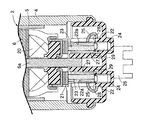
図1は本発明に係る電動燃料ポンプ装置の縦断面図(図2の1−1線断面図),図2は図1の2部拡大図,図3は図1の3−3線断面図,図4は図3の4−4線断面図である。
FIG. 1 is a longitudinal sectional view of the electric fuel pump device according to the present invention (cross-sectional view taken along line 1-1 of FIG. 2), FIG. 2 is an enlarged view of
先ず,図1において,電動燃料ポンプ装置1は,例えば自動二輪車や自動車のエンジンの燃料供給系に使用されるもので,電動モータ2と,これによって駆動される燃料ポンプ3とからなっている。
First, in FIG. 1, an electric
電動モータ2は金属製で円筒状のモータハウジング4を備えており,その内周面に永久磁石からなるステータ5が固定され,このステータ5内にロータ6が回転自在に配設される。
The
円筒状のモータハウジング4には,その一端を塞ぐようにして,例えばウエスコ型の燃料ポンプ3のポンプハウジング7が結合される。ポンプハウジング7は,合成樹脂製の外側ハウジング7aと,この外側ハウジング7aの内側に対置されて,それとの間に円形のポンプ室8を画成する,同じく合成樹脂製の内側ハウジング7bとから構成され,これら外側及び内側ハウジング7a,7bは,これらをモータハウジング4の一端部内周に回転不能に嵌合した後,該一端部を外側ハウジング7aの外側面側にカシメることにより,相互に接合されると同時に,モータハウジング4に結合される。
For example, a
上記ポンプ室8にはポンプインペラ10が回転自在に収容され,このポンプインペラ10の中心部に,電動モータ2のロータ6の中心部に結合したロータ軸6aが嵌合,連結される。また外側ハウジング7aには,ポンプ室8に通じる吸入ポート11が設けられ,内側ハウジング7bには,ポンプ室8をモータハウジング4内に通じさせる吐出ポート12が設けられる。吸入ポート11は,図示しない燃料タンク内の燃料油面下に連通されるようになっている。
A
モータハウジング4の他端部には,それを塞ぐように合成樹脂製の端子ホルダ14が結合される。即ち,端子ホルダ14は有底円筒状をなすと共に,外周にフランジ14bを有しており,このフランジ14bがモータハウジング4の他端部に嵌合され,該他端部をフランジ14bの外側面側にカシメることにより,端子ホルダ14はモータハウジング4に結合される。
A synthetic
図1〜図3に示すように,端子ホルダ14の端壁14aには一対の端子孔15,15が設けられ,これら端子孔15,15に一対の端子19,19が圧入により固定される。また同端壁14aには,端子19,19の外端部を囲繞するカプラ26が一体に成形される。
As shown in FIGS. 1 to 3, a pair of
さらに前記端壁14aには,外方に突出する燃料出口管16が一体に成形される。この燃料出口管16には,図示しないエンジンの燃料供給通路が接続されるようになっている。
Further, a
図1,図3及び図4に示すように,さらにまた前記端壁14aの中心部には,モータハウジング4内に開口する有底の軸孔17aを有する軸受ボス17が該端壁14aの内面から突出するように一体に成形され,その軸受ボス17と同軸上に配置される軸受ブッシュ18が前記ポンプハウジング7の内側ハウジング7bに固着され,これら軸受ボス17及び軸受ブッシュ18によりロータ軸6aの両端部が回転自在に支承される。
As shown in FIGS. 1, 3, and 4, a
軸受ボス17の内周面と,これと回転摺動するロータ軸6aの外周面との少なくとも一方には,ダイヤモンド・ライク・カーボンからなる硬質被膜が形成される。
A hard coating made of diamond-like carbon is formed on at least one of the inner peripheral surface of the
前記ロータの,端子ホルダ14側の端部には,ロータコイル20に連なる面型のコンミュテータ21が固着される。
A
一方,端子ホルダ14の端壁14aには,前記軸受ボス17を挟んで並ぶ一対の筒状のブラシガイド22,22が一体に成形され,これらブラシガイド22,22の一端は,該端壁14aの内面から長く突出し,他端は該端壁14aの外面から短く突出する。これらブラシガイド22,22は,軸受ボス17の軸孔17aと平行でモータハウジング4内に開口する有底で異形断面のガイド孔22a,22aを有しており,これらガイド孔22a,22aには,前記コンミュテータ21に摺接する異形断面の一対のブラシ23,23が摺動可能に嵌合されると共に,これらブラシ23,23をコンミュテータ21との圧接方向に付勢するコイルばね24,24が収納される。一対のブラシ23,23は,前記一対の端子19,19にリード線25,25を介して接続される。
On the other hand, on the
上記ブラシガイド22,22及び軸受ボス17間には,これらを互いに分離独立させる間隙27,27が設けられる。
Between the
またブラシガイド22,22には,軸受ボス17と反対側で軸方向に延びる第1切欠溝28,28と,軸受ボス17と隣接する側で軸方向に延びる第2切欠溝29,29とが形成される。その第1切欠溝28,28には,前記リード線25,25が移動可能に配置される。
The
次に,この実施例の作用について説明する。 Next, the operation of this embodiment will be described.
端子19,19を通して電動モータ2に給電して,それを作動すれば,ロータ軸6aがポンプインペラ10を回転駆動する。ポンプインペラ10が回転すると,図示しない燃料タンク内の燃料が吸入ポート11からポンプ室8に吸入され,昇圧されて吐出ポート12へと吐出され,モータハウジング4内を通過した後,燃料出口管16から,図示しないエンジンの燃料吸入通路へと圧送される。
When electric power is supplied to the
このような電動燃料ポンプ装置1において,モータハウジング4の,一対の端子19,19を保持する合成樹脂製の端子ホルダ14の端壁14aにそれぞれ一体に成形される軸受ボス17と,この軸受ボス17を挟んでそれと平行に並ぶ一対のブラシガイド22,22との間には,これらを分離独立させる間隙27,27が設けられるので,端子ホルダ14,軸受ボス17及びブラシガイド22,22の一体成形時,軸受ボス17及びブラシガイド22,22にそれぞれにヒケが発生しても,軸受ボス17及びブラシガイド22,22は,上記間隙27,27により,ヒケの影響を互いに遮断する。したがって軸受ボス17及びブラシガイド22,22をそれぞれ高精度に成形することが可能となり,この軸受ボス17に支承されるロータ軸6aの回転振動や早期摩耗を防いで耐久性の向上を図ることができ,同時にブラシガイド22,22に嵌装されるブラシ23,23の摺動安定性の向上を図ることができる。
In such an electric
またブラシガイド22,22は,その軸方向に延びる第1及び第2切欠溝28,29;28,29により周壁が二分されるので,その断面形状が異形であっても,ヒケによるブラシガイド22,22の成形精度の狂いを小さく抑えることができ,ブラシ23,23の摺動安定性の更なる向上を図ることができる。しかも第1切欠溝28,28は,ブラシ23,23及び端子19,19間を接続するリード線25,25の通路に利用されるので,構造の簡素化にも寄与し得る。
Further, since the peripheral walls of the brush guides 22 and 22 are divided into two by the first and
さらに軸受ボス17の内周面と,これに回転自在に支承されるロータ軸6aの外周面の少なくとも一方には,ダイヤモンド・ライク・カーボンからなる硬質被膜が形成されるので,ダイヤモンド・ライク・カーボンの摩擦係数が極めて低いことから,軸受ボス17及びロータ軸6a間の回転摩擦抵抗を小さくすることができ,したがって軸受ボス17が合成樹脂製であるにも拘らず,その耐摩耗性を保障することができる。
Further, since a hard coating made of diamond-like carbon is formed on at least one of the inner circumferential surface of the bearing
本発明は上記実施例に限定されるものではなく,その要旨を逸脱しない範囲で種々の設計変更が可能である。 The present invention is not limited to the above embodiment, and various design changes can be made without departing from the scope of the invention.
1・・・・電動燃料ポンプ装置
2・・・・電動モータ
3・・・・燃料ポンプ
4・・・・モータハウジング
6・・・・ロータ
6a・・・ロータ軸
7・・・・ポンプハウジング
14・・・端子ホルダ
14a・・端壁
17・・・軸受ボス
19・・・端子
21・・・コンミュテータ
22・・・ブラシガイド
23・・・ブラシ
24・・・ばね
27・・・間隙
DESCRIPTION OF
Claims (2)
前記軸受ボス(17)及び前記ブラシガイド(22)間に,これらを互いに分離独立させる間隙(27)を設けたことを特徴とする,電動燃料ポンプ装置。 A pump housing (7) of a fuel pump (3) driven by a rotor shaft (6a) coupled to a rotor (6) of the electric motor (2) is attached to one end of a motor housing (4) of the electric motor (2). A terminal holder (14) made of synthetic resin for supporting a power supply terminal (19) to the electric motor (2) is connected to the other end of the motor housing (4), and this terminal holder (14) The end wall (14a) has a bearing boss (17) for supporting the rotor shaft (6a) and a pair of cylindrical brush guides (22) arranged in parallel with the bearing boss (17). And a brush (23) slidably engaged with the planar commutator (21) provided at one end of the rotor (6) is slidably fitted to the brush guide (22). , This brush (23) commutator The electric fuel pump apparatus formed by housing a spring (24) for biasing the pressure contact direction and 21),
An electric fuel pump device characterized in that a gap (27) is provided between the bearing boss (17) and the brush guide (22) to separate them from each other.
前記軸受ボス(17)の内周面と,それと回転摺動する前記ロータ軸(6a)の外周面との少なくとも一方に,ダイヤモンド・ライク・カーボンからなる硬質被膜を形成したことを特徴とする,電動燃料ポンプ装置。
The electric fuel pump device according to claim 1,
A hard film made of diamond-like carbon is formed on at least one of the inner peripheral surface of the bearing boss (17) and the outer peripheral surface of the rotor shaft (6a) that rotates and slides thereon, Electric fuel pump device.
Priority Applications (1)
| Application Number | Priority Date | Filing Date | Title |
|---|---|---|---|
| JP2004122642A JP4065250B2 (en) | 2004-04-19 | 2004-04-19 | Electric fuel pump device |
Applications Claiming Priority (1)
| Application Number | Priority Date | Filing Date | Title |
|---|---|---|---|
| JP2004122642A JP4065250B2 (en) | 2004-04-19 | 2004-04-19 | Electric fuel pump device |
Publications (2)
| Publication Number | Publication Date |
|---|---|
| JP2005307768A true JP2005307768A (en) | 2005-11-04 |
| JP4065250B2 JP4065250B2 (en) | 2008-03-19 |
Family
ID=35436833
Family Applications (1)
| Application Number | Title | Priority Date | Filing Date |
|---|---|---|---|
| JP2004122642A Expired - Lifetime JP4065250B2 (en) | 2004-04-19 | 2004-04-19 | Electric fuel pump device |
Country Status (1)
| Country | Link |
|---|---|
| JP (1) | JP4065250B2 (en) |
Cited By (4)
| Publication number | Priority date | Publication date | Assignee | Title |
|---|---|---|---|---|
| WO2009139130A1 (en) * | 2008-05-12 | 2009-11-19 | 株式会社ミツバ | Fuel pump |
| JP2009275520A (en) * | 2008-05-12 | 2009-11-26 | Keihin Corp | Electric fuel pump device |
| KR100957352B1 (en) | 2008-06-20 | 2010-05-13 | 현대자동차주식회사 | Fuel pump for vehicle |
| JP2011122564A (en) * | 2009-12-14 | 2011-06-23 | Denso Corp | Fuel pump |
-
2004
- 2004-04-19 JP JP2004122642A patent/JP4065250B2/en not_active Expired - Lifetime
Cited By (5)
| Publication number | Priority date | Publication date | Assignee | Title |
|---|---|---|---|---|
| WO2009139130A1 (en) * | 2008-05-12 | 2009-11-19 | 株式会社ミツバ | Fuel pump |
| JP2009275520A (en) * | 2008-05-12 | 2009-11-26 | Keihin Corp | Electric fuel pump device |
| JP5325881B2 (en) * | 2008-05-12 | 2013-10-23 | 株式会社ミツバ | Fuel pump |
| KR100957352B1 (en) | 2008-06-20 | 2010-05-13 | 현대자동차주식회사 | Fuel pump for vehicle |
| JP2011122564A (en) * | 2009-12-14 | 2011-06-23 | Denso Corp | Fuel pump |
Also Published As
| Publication number | Publication date |
|---|---|
| JP4065250B2 (en) | 2008-03-19 |
Similar Documents
| Publication | Publication Date | Title |
|---|---|---|
| JP4893991B2 (en) | Fuel pump | |
| JP5391016B2 (en) | Electric pump | |
| KR19980702377A (en) | Fuel conveying unit | |
| JP4065250B2 (en) | Electric fuel pump device | |
| JP2003113796A (en) | Fuel pump | |
| JP2004263563A (en) | Fuel pump unit | |
| JP2007056705A (en) | Fuel pump | |
| JP2004052664A (en) | Motor driven pump | |
| US8007226B2 (en) | Fuel pump | |
| US20080085199A1 (en) | Fuel pump | |
| JP6793606B2 (en) | Pressure control device and fuel supply device | |
| JP5025560B2 (en) | Electric fuel pump device | |
| JP5844648B2 (en) | Electric pump | |
| JP2008064029A (en) | Fuel pump | |
| JP2005318668A (en) | Motor-driven pump apparatus | |
| JP6921666B2 (en) | Pressure controller and fuel supply | |
| JP7371024B2 (en) | Motor unit and liquid supply device | |
| US7950898B2 (en) | Fuel pump having impeller | |
| JP2009240135A (en) | Electric motor, and fuel pump unit | |
| JP2005312226A (en) | Electric motor | |
| JP4205475B2 (en) | Turbine type fuel pump | |
| JP2006087243A (en) | Brush holder apparatus and pump motor | |
| JP5204718B2 (en) | Fuel pump | |
| JP2008220026A (en) | Fuel pump | |
| JP7317477B2 (en) | Pump and its mounting method in vehicle |
Legal Events
| Date | Code | Title | Description |
|---|---|---|---|
| A977 | Report on retrieval |
Free format text: JAPANESE INTERMEDIATE CODE: A971007 Effective date: 20070530 |
|
| A131 | Notification of reasons for refusal |
Free format text: JAPANESE INTERMEDIATE CODE: A131 Effective date: 20070606 |
|
| A521 | Request for written amendment filed |
Free format text: JAPANESE INTERMEDIATE CODE: A523 Effective date: 20070806 |
|
| A131 | Notification of reasons for refusal |
Free format text: JAPANESE INTERMEDIATE CODE: A131 Effective date: 20070912 |
|
| A521 | Request for written amendment filed |
Free format text: JAPANESE INTERMEDIATE CODE: A523 Effective date: 20071106 |
|
| TRDD | Decision of grant or rejection written | ||
| A01 | Written decision to grant a patent or to grant a registration (utility model) |
Free format text: JAPANESE INTERMEDIATE CODE: A01 Effective date: 20071219 |
|
| A61 | First payment of annual fees (during grant procedure) |
Free format text: JAPANESE INTERMEDIATE CODE: A61 Effective date: 20071228 |
|
| R150 | Certificate of patent or registration of utility model |
Free format text: JAPANESE INTERMEDIATE CODE: R150 Ref document number: 4065250 Country of ref document: JP Free format text: JAPANESE INTERMEDIATE CODE: R150 |
|
| FPAY | Renewal fee payment (event date is renewal date of database) |
Free format text: PAYMENT UNTIL: 20110111 Year of fee payment: 3 |
|
| FPAY | Renewal fee payment (event date is renewal date of database) |
Free format text: PAYMENT UNTIL: 20110111 Year of fee payment: 3 |
|
| FPAY | Renewal fee payment (event date is renewal date of database) |
Free format text: PAYMENT UNTIL: 20120111 Year of fee payment: 4 |
|
| R250 | Receipt of annual fees |
Free format text: JAPANESE INTERMEDIATE CODE: R250 |
|
| FPAY | Renewal fee payment (event date is renewal date of database) |
Free format text: PAYMENT UNTIL: 20120111 Year of fee payment: 4 |
|
| FPAY | Renewal fee payment (event date is renewal date of database) |
Free format text: PAYMENT UNTIL: 20130111 Year of fee payment: 5 |
|
| R250 | Receipt of annual fees |
Free format text: JAPANESE INTERMEDIATE CODE: R250 |
|
| FPAY | Renewal fee payment (event date is renewal date of database) |
Free format text: PAYMENT UNTIL: 20130111 Year of fee payment: 5 |
|
| FPAY | Renewal fee payment (event date is renewal date of database) |
Free format text: PAYMENT UNTIL: 20140111 Year of fee payment: 6 |
|
| R250 | Receipt of annual fees |
Free format text: JAPANESE INTERMEDIATE CODE: R250 |
|
| R250 | Receipt of annual fees |
Free format text: JAPANESE INTERMEDIATE CODE: R250 |
|
| R250 | Receipt of annual fees |
Free format text: JAPANESE INTERMEDIATE CODE: R250 |
|
| R250 | Receipt of annual fees |
Free format text: JAPANESE INTERMEDIATE CODE: R250 |
|
| R250 | Receipt of annual fees |
Free format text: JAPANESE INTERMEDIATE CODE: R250 |
|
| R250 | Receipt of annual fees |
Free format text: JAPANESE INTERMEDIATE CODE: R250 |
|
| R250 | Receipt of annual fees |
Free format text: JAPANESE INTERMEDIATE CODE: R250 |
|
| R250 | Receipt of annual fees |
Free format text: JAPANESE INTERMEDIATE CODE: R250 |
|
| R250 | Receipt of annual fees |
Free format text: JAPANESE INTERMEDIATE CODE: R250 |
|
| S111 | Request for change of ownership or part of ownership |
Free format text: JAPANESE INTERMEDIATE CODE: R313111 |
|
| R350 | Written notification of registration of transfer |
Free format text: JAPANESE INTERMEDIATE CODE: R350 |
|
| R250 | Receipt of annual fees |
Free format text: JAPANESE INTERMEDIATE CODE: R250 |
|
| R250 | Receipt of annual fees |
Free format text: JAPANESE INTERMEDIATE CODE: R250 |
|
| R250 | Receipt of annual fees |
Free format text: JAPANESE INTERMEDIATE CODE: R250 |