JP2005305658A - Anti-ink adhesion power judging method and device - Google Patents
Anti-ink adhesion power judging method and device Download PDFInfo
- Publication number
- JP2005305658A JP2005305658A JP2004121673A JP2004121673A JP2005305658A JP 2005305658 A JP2005305658 A JP 2005305658A JP 2004121673 A JP2004121673 A JP 2004121673A JP 2004121673 A JP2004121673 A JP 2004121673A JP 2005305658 A JP2005305658 A JP 2005305658A
- Authority
- JP
- Japan
- Prior art keywords
- ink
- ink adhesion
- area
- adhesion
- paper
- Prior art date
- Legal status (The legal status is an assumption and is not a legal conclusion. Google has not performed a legal analysis and makes no representation as to the accuracy of the status listed.)
- Ceased
Links
Images


Abstract
Description
この発明は、インキの付着を防止する表面を有するインキ付着防止部材のインキ付着防止性能を判断するインキ付着防止性能判断方法および装置に関するものである。 The present invention relates to an ink adhesion preventing performance judging method and apparatus for judging the ink adhesion preventing performance of an ink adhesion preventing member having a surface for preventing ink adhesion.
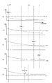
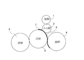
図74はオフセット輪転印刷機における印刷機構の概略構成を示す図である。同図において、1は刷版が装着された版胴、2はゴム胴、3は圧胴、4は渡胴である。この印刷機構において、インキは版胴1からゴム胴2に転写された後、ゴム胴2と圧胴3との間に送入される用紙6へと圧着転移し、用紙6にインキ像7が形成される。
FIG. 74 is a diagram showing a schematic configuration of a printing mechanism in an offset rotary printing press. In the figure, 1 is a plate cylinder on which a printing plate is mounted, 2 is a rubber cylinder, 3 is an impression cylinder, and 4 is a transfer cylinder. In this printing mechanism, the ink is transferred from the
通常、圧胴3としては、金属シリンダ表面をクロムメッキにより表面仕上げしたものが使用されている。この圧胴3を備えた両面専用印刷機(例えば、特許文献1参照)で、印刷を行う場合、その第1面(表面)にインキ像7が形成された用紙6が次工程において、図74と同様の構成のゴム胴2と圧胴3との間に送入されると(図75参照)、用紙6の表面に印刷されたインキ像7が圧胴3の周面にインキ像7’として転移する。このため、続いて送られてくる用紙6の表面に圧胴3の周面に転移したインキ像7’が再度転写され、用紙6の表面が汚れてしまい、印刷品質の低下を招く。
Usually, as the
この問題は、反転機で両面印刷を行う場合にも生じる。反転機(例えば、特許文献2参照)では、印刷された用紙6の第1面(表面)が反転後には第2面(裏面)となり、この反転された用紙6の表面に印刷が施される。この場合、反転後の用紙6がゴム胴2と圧胴3との間に送入されると(図76参照)、用紙6の裏面に印刷されたインキ像7が圧胴3の周面にインキ像7’として転移する。このため、続いて送られてくる用紙6の裏面に圧胴3の周面に転移したインキ像7’が再度転写され、用紙6の裏面が汚れてしまい、印刷品質の低下を招く。
This problem also occurs when duplex printing is performed with a reversing machine. In the reversing machine (see, for example, Patent Document 2), the first surface (front surface) of the printed
また、片面印刷の場合においても、使用する用紙6の大きさは、幅広のものから幅狭のものまであり、図77に示すように幅狭の用紙6に印刷する場合には、用紙6の存在しない幅部においてゴム胴2と圧胴3とが直接接触することになり、版胴1上のわずかな汚れがゴム胴2を介して圧胴3へと転写され、圧胴3の周面が汚れる。次に、圧胴3が汚れたまま幅広の用紙6が通過すると、この圧胴3の汚れがその用紙6へと付着して汚れが生じてしまう。
Also, in the case of single-sided printing, the size of the
このため、最近では、図78に示すように、インキの付着を防止する表面を有するインキ付着防止部材8を圧胴3の周面に装着し、用紙6が汚れることを防止している。なお、渡胴や排紙胴、反転胴なども印刷後のインキが付着して汚れる。このため、これらの胴に対しても圧胴と同様に、インキ付着防止部材をその周面に装着することがある。このようにインキ付着防止部材は圧胴だけではなく、他の胴にも装着されることがあるが、圧胴の周面に装着されるインキ付着防止部材を特に圧胴プレートと呼んでいる。また、インキ付着防止部材については、例えば特許文献3に記載されている。この特許文献3に示されたインキ付着防止部材(プレート)では、金属製板材上に金属溶射層、およびセラミックス溶射層と低表面エネルギー性樹脂層とからなる複合被覆皮膜を形成するようにしている。また、圧胴プレートの圧胴への装着方法については、特許文献4に記載されている。
Therefore, recently, as shown in FIG. 78, an ink
しかしながら、インキ付着防止部材を装着したからといって、そこで完全にインキを弾くことができるわけではない。インキ付着防止部材の表面には徐々にインキが付着し、その表面が徐々に劣化して行く。このため、ある程度その表面が劣化した場合、新しいインキ付着防止部材と交換しなければならない。
従来は、用紙に印刷された絵柄の汚れ具合をオペレータが見て、装着されているインキ付着防止部材の劣化を経験と勘により判断し、新しいものと交換していた。このため、オペレータに熟練が要求されると共に、大きな負担がかかる。また、インキ付着防止部材の劣化の判断を誤ると、インキ付着防止部材が劣化したままで印刷が続けられ、損紙が大量に発生してしまうという虞れもある。
However, just because the ink adhesion preventing member is mounted, the ink cannot be completely repelled there. Ink gradually adheres to the surface of the ink adhesion preventing member, and the surface gradually deteriorates. For this reason, when the surface deteriorates to some extent, it must be replaced with a new ink adhesion preventing member.
Conventionally, an operator sees the degree of dirt on a picture printed on a sheet, determines the deterioration of the attached ink adhesion preventing member based on experience and intuition, and replaces it with a new one. For this reason, skill is required for the operator and a large burden is applied. Further, if the determination of deterioration of the ink adhesion preventing member is mistaken, printing may be continued while the ink adhesion preventing member is deteriorated, and a large amount of paper loss may occur.
本発明は、このような課題を解決するためになされたもので、その目的とするところは、インキ付着防止部材の劣化を簡単かつ確実に判断することができるインキ付着防止性能判断方法および装置を提供することにある。 The present invention has been made to solve such problems, and an object of the present invention is to provide an ink adhesion prevention performance judgment method and apparatus capable of easily and reliably judging the deterioration of the ink adhesion prevention member. It is to provide.
このような目的を達成するために、第1発明(請求項1に係る発明)は、インキ付着防止部材がその周面に装着された回転体を回転させる工程と、搬送される用紙をインキ付着防止部材の表面に押し付ける工程と、用紙のインキ付着防止部材に押し付けられた面を撮像する工程と、撮像された用紙の画像データよりその用紙に付着しているインキの付着面積を求める工程と、求められた用紙のインキの付着面積よりインキ付着防止部材のインキ付着防止性能を判断する工程とを設けたものである。 In order to achieve such an object, the first invention (the invention according to claim 1) includes a step of rotating a rotating body having an ink adhesion preventing member mounted on a peripheral surface thereof, and an ink adhesion of a sheet to be conveyed. A step of pressing against the surface of the prevention member, a step of imaging the surface pressed against the ink adhesion prevention member of the paper, a step of determining the adhesion area of the ink attached to the paper from the image data of the captured paper, And a step of determining the ink adhesion preventing performance of the ink adhesion preventing member from the obtained ink adhesion area of the paper.
この発明において、回転体とは、圧胴や渡胴,排紙胴,反転胴などのインキが付着する虞れのある胴を指す。本発明では、搬送される用紙を、その回転体の周面に装着されているインキ付着防止部材の表面に押し付ける。例えば、回転体が圧胴であれば、ゴム胴を圧胴に圧接させ、この状態(胴入れ状態)でゴム胴と圧胴との間に用紙を通す。この際、インキ付着防止部材の表面にインキが付着していれば、このインキが用紙に転写される。本発明では、この用紙のインキ付着防止部材に押し付けられた面(インキが転写された面)を撮像し、この撮像した用紙の画像データよりその用紙に付着しているインキの付着面積を求め、この求めたインキの付着面積よりインキ付着防止部材のインキ付着防止性能を判断する。 In the present invention, the rotator refers to a cylinder to which ink may adhere such as an impression cylinder, a transfer cylinder, a paper discharge cylinder, and a reversing cylinder. In the present invention, the sheet to be conveyed is pressed against the surface of the ink adhesion preventing member mounted on the peripheral surface of the rotating body. For example, if the rotating body is an impression cylinder, the rubber cylinder is brought into pressure contact with the impression cylinder, and the paper is passed between the rubber cylinder and the impression cylinder in this state (cylinder insertion state). At this time, if ink adheres to the surface of the ink adhesion preventing member, the ink is transferred to the paper. In the present invention, the surface pressed against the ink adhesion preventing member of the paper (the surface on which the ink is transferred) is imaged, and the adhesion area of the ink adhering to the paper is determined from the image data of the imaged paper, The ink adhesion preventing performance of the ink adhesion preventing member is determined from the obtained ink adhesion area.
なお、用紙のインキ付着防止部材に押し付けられた面の撮像はオンライン(搬送中に撮像)で行うようにしてもよいし、オフラインで行うようにしてもよい。例えば、オフラインで行う場合、インキ付着防止部材に押し付けた用紙を排紙後、その用紙をオペレータが測定器のところまで運び、そこで撮像する。 Note that the surface of the sheet pressed against the ink adhesion preventing member may be imaged online (imaged during conveyance) or offline. For example, in the case of off-line, after the paper pressed against the ink adhesion preventing member is discharged, the operator carries the paper to the measuring instrument and images it there.
本発明において、インキ付着防止部材のインキ付着防止性能の判断は、例えば次のようにして行う。
(1)求めたインキの付着面積と予め定められている許容面積とを比較し、インキの付着面積が許容面積よりも大きい場合に、インキ付着防止部材のインキ付着防止性能が劣化したと判断する(第2発明:請求項2に係る発明)。
(2)求めたインキの付着面積より用紙に付着しているインキの付着面積率を求め、このインキの付着面積率と予め定められている許容面積率とを比較し、インキの付着面積率が許容面積率よりも大きい場合に、インキ付着防止部材のインキ付着防止性能が劣化したと判断する(第3発明:請求項3に係る発明)。
In the present invention, the ink adhesion preventing performance of the ink adhesion preventing member is determined as follows, for example.
(1) The obtained ink adhesion area is compared with a predetermined allowable area, and when the ink adhesion area is larger than the allowable area, it is determined that the ink adhesion preventing performance of the ink adhesion preventing member has deteriorated. (Second invention: Invention according to claim 2).
(2) Obtain the ink adhesion area ratio that adheres to the paper from the determined ink adhesion area, and compare the ink adhesion area ratio with a predetermined allowable area ratio. When it is larger than the allowable area ratio, it is determined that the ink adhesion preventing performance of the ink adhesion preventing member has deteriorated (third invention: invention according to claim 3).
また、本発明において、用紙のインキの付着面積は、例えば次のようにして求める。
(1)撮像した用紙の画像データを2値化処理し、この2値化処理した画像データより用紙に付着しているインキの付着面積を求める(第4発明:請求項4に係る発明)。
(2)撮像した用紙の画像データを2値化処理し、この2値化処理した画像データより連続してインキが付着した範囲の面積を求め、この連続してインキが付着した範囲の面積と予め定められている閾値とを比較し、連続してインキが付着した範囲の面積が閾値よりも大きいものだけを抽出し、その抽出した面積の合計をインキの付着面積とする(第5発明:請求項5に係る発明)。
この発明では、2値化処理することにより、用紙の擦れ等による淡い汚れが排除され、確実にインキが付着した範囲のみを検出することができる。また、連続してインキが付着した範囲の面積が閾値よりも大きいものだけを抽出し、その抽出した面積の合計をインキ付着面積とすることにより、製紙時に用紙に発生する小さな黒点等を誤って加算することが排除できる。
In the present invention, the adhesion area of the ink on the paper is determined as follows, for example.
(1) The image data of the imaged paper is binarized, and the adhesion area of the ink adhering to the paper is obtained from the binarized image data (fourth invention: invention according to claim 4).
(2) The image data of the imaged paper is binarized, and the area of the area where ink is continuously applied is obtained from the binarized image data. Comparison is made with a predetermined threshold value, and only the area where the area where the ink is continuously adhered is larger than the threshold value is extracted, and the total of the extracted areas is defined as the ink adhesion area (fifth invention: Invention according to claim 5).
In the present invention, by performing binarization processing, light stains due to paper rubbing or the like are eliminated, and it is possible to reliably detect only a range where ink has adhered. In addition, by extracting only the area where the area where the ink is continuously applied is larger than the threshold, and making the sum of the extracted areas the ink adhesion area, small black spots generated on the paper at the time of papermaking are mistakenly detected. Addition can be eliminated.
第6発明(請求項6に係る発明)は、インキ付着防止部材がその周面に装着された回転体を回転させる工程と、搬送される複数枚の用紙をインキ付着防止部材の表面に順番に押し付ける工程と、複数枚の用紙のインキ付着防止部材に押し付けられた面を撮像する工程と、撮像された用紙の画像データよりその用紙に付着しているインキの付着面積を求める工程と、求められた用紙のインキの付着面積と予め定められている許容面積とを比較し、インキの付着面積が許容面積よりも小さくなった最初の用紙のインキ付着防止部材に押し付けられた順位を求める工程と、求められた順位と予め定められている許容順位とを比較し、求められた順位が許容順位よりも後ろにある場合に、インキ付着防止部材のインキ付着防止性能が劣化したと判断する工程とを設けたものである。 A sixth invention (invention according to claim 6) is a method of rotating a rotating body having an ink adhesion preventing member mounted on its peripheral surface, and a plurality of sheets of paper to be conveyed on the surface of the ink adhesion preventing member in order. A step of pressing, a step of imaging a surface pressed against an ink adhesion preventing member of a plurality of sheets, a step of determining an adhesion area of ink adhered to the sheet from the image data of the captured sheet, and Comparing the ink adhering area of the paper and the predetermined permissible area, and determining the order of pressing against the ink adhering prevention member of the first paper where the ink adhering area is smaller than the allowable area; The calculated rank is compared with a predetermined allowable rank, and when the calculated rank is behind the allowable rank, it is determined that the ink adhesion prevention performance of the ink adhesion preventing member has deteriorated. It is provided with a a process.
この発明では、搬送される複数枚の用紙を、回転体の周面に装着されているインキ付着防止部材の表面に順番に押し付ける。例えば、回転体が圧胴であれば、ゴム胴を圧胴に圧接させ、この状態(胴入れ状態)でゴム胴と圧胴との間に複数枚の用紙を順番に通す。この際、インキ付着防止部材の表面にインキが付着していれば、このインキが用紙に転写される。本発明では、この複数枚の用紙のインキ付着防止部材に押し付けられた面(インキが転写された面)を撮像し、この撮像した用紙の画像データよりその用紙に付着しているインキの付着面積を求め、この求めたインキの付着面積より次のようにしてインキ付着防止部材のインキ付着防止性能を判断する。 In the present invention, a plurality of sheets to be conveyed are sequentially pressed against the surface of the ink adhesion preventing member mounted on the peripheral surface of the rotating body. For example, if the rotating body is an impression cylinder, the rubber cylinder is brought into pressure contact with the impression cylinder, and a plurality of sheets are sequentially passed between the rubber cylinder and the impression cylinder in this state (cylinder insertion state). At this time, if ink adheres to the surface of the ink adhesion preventing member, the ink is transferred to the paper. In the present invention, the surface of the plurality of papers pressed against the ink adhesion preventing member (the surface on which the ink has been transferred) is imaged, and the adhesion area of the ink adhering to the paper from the image data of the imaged paper The ink adhesion prevention performance of the ink adhesion prevention member is determined from the obtained ink adhesion area as follows.
通常、インキの付着面積は、用紙が送られてくる順番に低下する。インキ付着防止部材のインキ付着防止性能が高ければ、付着しているインキ量が少ないため、少ない紙枚数でインキの付着面積は低下安定する。これに対し、インキ付着防止部材のインキ付着防止性能が低ければ、付着しているインキ量が多いため、インキ付着面積が低下安定するまでには多くの紙枚数を必要とする。本発明では、この原理を元に、求めた用紙のインキの付着面積と予め定められている許容面積とを比較し、インキの付着面積が許容面積よりも小さくなった最初の用紙のインキ付着防止部材に押し付けられた順位(Nx)を求める。そして、この求めた順位と予め定められている許容順位(Nth)とを比較し、求めた順位が許容順位よりも後ろにある場合に(Nx>Nth)、インキ付着防止部材のインキ付着防止性能が劣化したと判断する。なお、この第6発明では、インキの付着面積でインキ付着防止性能の劣化を判断するが、インキの付着面積率で判断してもよい(第7発明:請求項7に係る発明)。 Usually, the ink adhesion area decreases in the order in which the sheets are fed. If the ink adhesion preventing performance of the ink adhesion preventing member is high, the amount of ink adhering is small, so that the ink adhesion area decreases and stabilizes with a small number of sheets. On the other hand, if the ink adhesion preventing performance of the ink adhesion preventing member is low, the amount of ink adhering is large. Therefore, a large number of sheets are required until the ink adhesion area is lowered and stabilized. In the present invention, based on this principle, the ink adhesion area of the obtained paper is compared with a predetermined allowable area, and the ink adhesion prevention of the first paper in which the ink adhesion area becomes smaller than the allowable area is prevented. The order (Nx) pressed against the member is obtained. Then, the obtained rank is compared with a predetermined permissible rank (Nth), and when the obtained rank is behind the permissible rank (Nx> Nth), the ink adhesion prevention performance of the ink adhesion prevention member. Is judged to have deteriorated. In this sixth aspect of the invention, the deterioration of the ink adhesion prevention performance is judged by the ink adhesion area, but it may be judged by the ink adhesion area ratio (seventh invention: invention according to claim 7).
第8発明(請求項8に係る発明)は、インキ付着防止部材がその周面に装着された回転体を回転させる工程と、搬送される複数枚の用紙をインキ付着防止部材の表面に順番に押し付ける工程と、予め定められている順位に押し付けられた用紙のインキ付着防止部材に押し付けられた面を撮像する工程と、撮像された用紙の画像データよりその用紙に付着しているインキの付着面積を求める工程と、求められた用紙のインキの付着面積と予め定められている許容面積とを比較し、インキの付着面積が許容面積よりも大きい場合に、インキ付着防止部材のインキ付着防止性能が劣化したと判断する工程とを設けたものである。 The eighth invention (the invention according to claim 8) comprises a step of rotating a rotating body having an ink adhesion preventing member mounted on its peripheral surface, and a plurality of sheets of paper to be conveyed in order on the surface of the ink adhesion preventing member. The step of pressing, the step of imaging the surface pressed against the ink adhesion prevention member of the paper pressed in a predetermined order, and the adhesion area of the ink attached to the paper from the image data of the captured paper The ink adhesion prevention performance of the ink adhesion prevention member is compared when the ink adhesion area of the obtained paper is compared with the predetermined allowable area and the ink adhesion area is larger than the allowable area. And a step of determining that the deterioration has occurred.
この発明では、予め定められている順位に押し付けられた用紙のインキ付着防止部材に押し付けられた面が撮像され、撮像された用紙の画像データよりその用紙に付着しているインキの付着面積が求められる。通常、インキの付着面積は、用紙が送られてくる順番に低下する。インキ付着防止部材のインキ付着防止性能が高ければ、付着しているインキ量が少ないため、予め定められている順位の用紙のインキの付着面積は少なくなる。これに対し、インキ付着防止部材のインキ付着防止性能が低ければ、付着しているインキ量が多いため、予め定められている順位の用紙のインキの付着面積は多くなる。本発明では、この原理を元に、複数枚の用紙のうち予め定められている順位の用紙のインキの付着面積と予め定められている許容面積とを比較し、インキの付着面積が許容面積よりも大きい場合に、インキ付着防止部材のインキ付着防止性能が劣化したと判断する。なお、この第8発明では、インキの付着面積でインキ付着防止性能の劣化を判断するが、インキの付着面積率で判断してもよい(第9発明:請求項9に係る発明)。 In this invention, the surface pressed against the ink adhesion prevention member of the paper pressed in a predetermined order is imaged, and the adhesion area of the ink adhering to the paper is obtained from the image data of the imaged paper. It is done. Usually, the ink adhesion area decreases in the order in which the sheets are fed. If the ink adhesion preventing performance of the ink adhesion preventing member is high, the amount of ink adhering is small, and therefore, the ink adhesion area of the paper in a predetermined order is reduced. On the other hand, if the ink adhesion preventing performance of the ink adhesion preventing member is low, the amount of ink adhering is large, and therefore, the ink adhesion area of the paper of a predetermined order increases. In the present invention, based on this principle, the ink adhesion area of a predetermined number of sheets among a plurality of sheets is compared with a predetermined allowable area, and the ink adhesion area is more than the allowable area. If it is too large, it is determined that the ink adhesion preventing performance of the ink adhesion preventing member has deteriorated. In the eighth invention, the deterioration of the ink adhesion prevention performance is judged by the ink adhesion area, but it may be judged by the ink adhesion area ratio (the ninth invention: the invention according to claim 9).
上述した第1〜第9発明では、インキの付着面積やインキの付着面積率でインキ付着防止性能の劣化を判断するが、インキの非付着面積やインキの非付着面積率でインキ付着防止性能の劣化を判断してもよい(第10〜第18発明:請求項10〜18に係る発明)。また、本発明は、第1〜第18発明の方法を適用した装置としても構成することができる(第19〜第36発明:請求項19〜36に係る発明)。
In the first to ninth inventions described above, the deterioration of the ink adhesion prevention performance is judged by the ink adhesion area and the ink adhesion area ratio, but the ink adhesion prevention performance is determined by the ink non-adhesion area and the ink non-adhesion area ratio. Deterioration may be judged (10th to 18th inventions: inventions according to
本発明によれば、用紙のインキ付着防止部材に押し付けられた面を撮像し、この撮像した用紙の画像データよりその用紙に付着しているインキの付着面積やインキの非付着面積を求め、この求めたインキの付着面積(インキの付着面積から求められるインキの付着面積率を含む)やインキの非付着面積(インキの非付着面積から求められるインキの非付着面積率を含む)に基づいてインキ付着防止部材のインキ付着防止性能を定量的に判断するようにしたので、インキ付着防止部材の劣化を簡単かつ確実に判断することができるようになり、熟練したオペレータを登用する必要がなくなり、損紙が大量に発生してしまう虞れもなくなる。 According to the present invention, the surface of the paper pressed against the ink adhesion preventing member is imaged, and the adhesion area of the ink adhering to the paper or the non-adhesion area of the ink is obtained from the image data of the imaged paper. Ink based on the determined ink adhesion area (including the ink adhesion area ratio determined from the ink adhesion area) and the ink non-adhesion area (including the ink non-adhesion area ratio determined from the ink non-adhesion area) Since the ink adhesion prevention performance of the adhesion prevention member is determined quantitatively, the deterioration of the ink adhesion prevention member can be judged easily and reliably, eliminating the need to hire skilled operators and There is no risk of large amounts of paper.
以下、本発明を図面に基づいて詳細に説明する。
〔専用両面印刷機〕
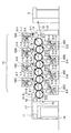
図1は本発明のインキ付着防止性能判断方法の実施に用いる印刷機の一例を示す概略構成図である。この印刷機は4色の専用両面印刷機である。
Hereinafter, the present invention will be described in detail with reference to the drawings.
[Dedicated duplex printing machine]
FIG. 1 is a schematic configuration diagram showing an example of a printing machine used for carrying out the ink adhesion prevention performance judging method of the present invention. This printing machine is a four-color dedicated duplex printing machine.
同図において、9は給紙部、10は印刷部、11は排紙部であり、印刷部10の最先頭の圧胴3−1には、給紙部9にパイルされた枚葉紙(用紙)がレジスタボード12,スインググリッパ装置13,渡胴14を介して給紙され、印刷部10の最後尾の圧胴3−8からは、印刷終了後の枚葉紙が搬送胴15を介して排紙胴16に受け渡され、ここからチェーングリッパ17によりパイル昇降装置18のパイル板上に排紙されるようになっている。
In the drawing, 9 is a paper feeding unit, 10 is a printing unit, and 11 is a paper discharge unit. The topmost impression cylinder 3-1 of the
印刷部10は、4個の表面側印刷ユニット19A〜19Dと、同じく4個の裏面側印刷ユニット20A〜20Dとから構成されている。第1〜第4色目の表面側印刷ユニット19A〜19Dは、圧胴3の上部に、ゴム胴2,版胴1,インキ部5を設けて形成され、第1〜第4色目の裏面側印刷ユニット20A〜20Dは、圧胴3の下部に、ゴム胴2,版胴1,インキ部5を設けて形成されている。
The
また、印刷部10において、表面側印刷ユニット19A〜19Dと裏面側印刷ユニット20A〜20Dとは、第1色目の表面側印刷ユニット19Aの次に第1色目の裏面側印刷ユニット20Aを、その次に第2色目の表面側印刷ユニット19Bというように交互に配置されている。
In the
この専用両面印刷機において、枚葉紙は渡胴14から第1色目の表面側印刷ユニット19Aの圧胴3−1に受け渡されて、その表面に第1色目の印刷が施され、次いで第1色目の裏面側印刷ユニット20Aの圧胴3−2に受け渡されて、その裏面に第1色目の印刷が施される。その後、同様にして、第2〜第4色目の表面側印刷ユニット19B〜19Dおよび第2〜第4色目の裏面側印刷ユニット20B〜20Dにより、枚葉紙の表裏面に交互に第2〜第4色目の印刷が施される。
In this dedicated duplex printing machine, the sheet is transferred from the
この専用両面印刷機の圧胴3−1〜3−8の周面には圧胴プレート8が装着されている。この例では、圧胴3−1〜3−8の周面に分割して2つの圧胴プレート8を装着しているが、圧胴3−1〜3−8の全周に1つの圧胴プレートを装着してもよいことは言うまでもない。また、圧胴プレート8は、特許文献3に示されているようなものであって、インキの付着を防止する表面を有している。また、圧胴プレート8の圧胴3−1〜3−8への装着方法については、特許文献4に記載されているので、ここでの説明は省略する。
An
また、この専用両面印刷機の圧胴3−1〜3−8に対しては、カメラ21−1〜21−8が設けられている。例えば、圧胴3−1に対するカメラ21−1は、圧胴3−1とゴム胴2−2との間の圧胴3−2の周面と対接する位置に設けられている。圧胴3−2〜3−7に対するカメラ21−2〜21−7もカメラ21−1と同様の位置に設けられている。圧胴3−8に対するカメラ21−8は、圧胴3−8と排紙胴16との間の搬送胴15の周面と対接する位置に設けられている。
Further, cameras 21-1 to 21-8 are provided for the impression cylinders 3-1 to 3-8 of the dedicated duplex printing machine. For example, the camera 21-1 with respect to the impression cylinder 3-1 is provided at a position in contact with the peripheral surface of the impression cylinder 3-2 between the impression cylinder 3-1 and the rubber cylinder 2-2. The cameras 21-2 to 21-7 with respect to the impression cylinders 3-2 to 3-7 are also provided at the same positions as the camera 21-1. The camera 21-8 with respect to the impression cylinder 3-8 is provided at a position in contact with the peripheral surface of the
〔反転機〕
図2は本発明のインキ付着防止性能判断方法の実施に用いる印刷機の他の例を示す概略構成図である。この印刷機は片面印刷と両面印刷とを選択可能な反転機構付枚葉輪転印刷機である。
〔Reversing machine〕
FIG. 2 is a schematic configuration diagram showing another example of a printing press used for carrying out the ink adhesion preventing performance judging method of the present invention. This printing press is a sheet-fed rotary printing press with a reversing mechanism capable of selecting single-sided printing or double-sided printing.
同図において、22は反転胴であり、2色目の印刷ユニット23Bの圧胴3−2と3色目の印刷ユニット23Cの圧胴3−3との間に両胴に対接して設けられている。片面印刷の場合、枚葉紙は、反転胴23において反転されることなく、3色目の印刷ユニット23Cの圧胴3−3に受け渡される。両面印刷の場合、枚葉紙は、反転胴23において反転されて、3色目の印刷ユニット23Cの圧胴3−3に受け渡される。すなわち、1色目の印刷ユニット23A,2色目の印刷ユニット23Bで印刷された枚葉紙の第1面(表面)が反転胴22によって反転されて第2面(裏面)とされ、この反転された枚葉紙が3色目の印刷ユニット23Cの圧胴3−3に受け渡される。
In the figure,
この反転機構付枚葉輪転印刷機の圧胴3−1〜3−4の周面には圧胴プレート8が装着されている。また、圧胴3−1〜3−4に対しては、カメラ21−1〜21−4が設けられている。例えば、圧胴3−1に対するカメラ21−1は、圧胴3−1からの渡胴4−1への枚葉紙の受け渡し部の渡胴4−1の周面と対接する位置に設けられている。圧胴3−2〜3−4に対するカメラ21−2〜21−4もカメラ21−1と同様の位置に設けられている。
An
〔実施の形態1:インキの付着面積でインキ付着防止性能判断〕
先ず、実施の形態1として、インキの付着面積でインキ付着防止性能の判断を行う方式について説明する。
図3は図1や図2に示した印刷機に付設されたインキ付着防止性能判断装置100(100A)を示すブロック図である。
[Embodiment 1: Determination of ink adhesion prevention performance based on ink adhesion area]
First, as the first embodiment, a method for determining the ink adhesion prevention performance based on the ink adhesion area will be described.
FIG. 3 is a block diagram showing an ink adhesion prevention performance judging device 100 (100A) attached to the printing machine shown in FIGS.
図3において、101はCPU、102はROM、103はRAM、104は入力装置、105は表示器、106は出力装置(フレキシブルディスクドライブ、プリンタ等)、107は検査対象のユニット番号Uの設定を行うための設定器(ユニット番号設定器)、108は検査に使用する用紙の白紙印刷枚数Nの設定を行うための設定器(印刷枚数設定器)、109は検査する用紙の測定位置情報Pの設定を行うための設定器(測定位置設定器)、110は印刷機の原動モータの回転に伴ってクロックパルスを発生するロータリーエンコーダ、111はロータリーエンコーダ110からのクロックパルスをカウントする測定位置用カウンタ、112は測定器、113は測定器112からのアナログ信号をデジタル信号に変換するA/D変換器、114〜120は入出力インターフェイス(I/O、I/F)、M1〜M15はメモリである。測定器112は、図1に示した印刷機ではカメラ21−1〜21−8に相当し、図2に示した印刷機ではカメラ21−1〜21−4に相当する。入力装置104にはスタートスイッチSW1が設けられている。
In FIG. 3, 101 is a CPU, 102 is a ROM, 103 is a RAM, 104 is an input device, 105 is a display, 106 is an output device (flexible disk drive, printer, etc.), 107 is a unit number U to be inspected. A setting device (unit number setting device) 108 for performing, a setting device (printing number setting device) for setting the number N of printed blank sheets of paper used for the inspection, and 109 a measurement position information P of the paper to be inspected A setting device (measurement position setting device) for performing setting, 110 is a rotary encoder that generates clock pulses as the driving motor of the printing press rotates, and 111 is a measurement position counter that counts clock pulses from the
CPU101は、インターフェイス114〜120を介して与えられる各種入力情報を得て、RAM103にアクセスしながら、ROM102に格納されたプログラムに従って動作する。ROM102には印刷機における圧胴3の周面に装着された圧胴プレート8のインキ付着防止性能を判断するためのプログラム(インキ付着防止性能判断プログラム)が格納されている。なお、このインキ付着防止性能判断プログラムは、例えばCD−ROMなどの記録媒体に記録された状態で提供し、この記録媒体から読み出してハードディスクにインストールするようにしてもよい。
The
メモリM1には、ユニット番号設定器107を介して設定される検査対象のユニット番号Uが書き込まれる。
メモリM2には、印刷枚数設定器108を介して設定される検査に使用する用紙の白紙印刷枚数Nが書き込まれる。
メモリM3には、測定位置設定器109を介して設定される検査する用紙の測定位置情報Pが書き込まれる。
The unit number U to be inspected set via the unit
In the memory M2, the number N of blank sheets to be used for the inspection set through the print
In the memory M3, measurement position information P of a sheet to be inspected set through the measurement
メモリM4には、検査する用紙の測定位置情報Pに相応する測定位置用カウンタ111のカウント値Cpsが書き込まれる。
メモリM5には、測定位置用カウンタ111の現在のカウント値Cprが書き込まれる。なお、測定位置用カウンタ111は、印刷機の回転角が原点に戻る毎に、ロータリーエンコーダ110からのゼロパルスによってリセットされる。
In the memory M4, the count value Cps of the
The current count value Cpr of the
メモリM6には、後述する測定器112からの画像データZ1−1〜Zn−mが保存される。
メモリM7には、メモリM6に保存された画像データZ1−1〜Zn−mを2値化処理する際のスレッシュレベルth1が書き込まれている。
メモリM8には、メモリM7中のスレッシュレベルth1を用いて2値化処理された画像データZ1−1’〜Zn−m’が保存される。
In the memory M6, image data Z1-1 to Zn-m from the measuring
The memory M7 is written with a threshold level th1 for binarizing the image data Z1-1 to Zn-m stored in the memory M6.
The memory M8 stores image data Z1-1 ′ to Zn-m ′ binarized using the threshold level th1 in the memory M7.
メモリM9には、メモリM8に保存された画像データZ1−1’〜Zn−m’に対して後述するゾーベル微分を行って得られるゾーベル微分値が書き込まれる。
メモリM10には、メモリM9に書き込まれたゾーベル微分値に基づいてエッジ判断を行う際に用いるエッジ判断基準値ethが書き込まれている。
メモリM11には、メモリM10中のエッジ判断基準値ethを用いて抽出されるエッジ(2値化レベルの「1」)が記憶される。
In the memory M9, a Sobel differential value obtained by performing a Sobel differential described later on the image data Z1-1 ′ to Zn-m ′ stored in the memory M8 is written.
In the memory M10, an edge determination reference value eth used when performing an edge determination based on the Sobel differential value written in the memory M9 is written.
The memory M11 stores an edge (binarization level “1”) extracted using the edge determination reference value eth in the memory M10.
メモリM12には、インキ付着部判定面積Sthが書き込まれている。
メモリM13には、メモリM11内のエッジ毎にそのエッジで囲まれた範囲の面積Sが書き込まれる。
メモリM14には、メモリM11内の全てのエッジで囲まれた範囲の面積Sの合計値(インキ付着部の合計面積)STが書き込まれる。
メモリM15には、インキ付着防止性能判断基準面積STthが書き込まれている。
In the memory M12, the ink adhesion portion determination area Sth is written.
In the memory M13, for each edge in the memory M11, an area S in a range surrounded by the edge is written.
In the memory M14, a total value (total area of ink adhering portions) ST of an area S in a range surrounded by all edges in the memory M11 is written.
In the memory M15, an ink adhesion prevention performance determination reference area STth is written.
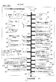
図4は図1や図2に示した印刷機に付設された印刷機制御装置200を示すブロック図である。この印刷機制御装置200は上述したインキ付着防止性能判断装置100Aとの間で信号の授受を行う。
FIG. 4 is a block diagram showing a printing
図4において、201はCPU、202はROM、203はRAM、204は印刷機へ用紙が1枚給紙される毎に1パルスの給紙検出信号を送出する給紙枚数用検出器、205は給紙枚数用検出器204からの給紙検出信号をカウントする給紙枚数用カウンタ、206は印刷機の原動モータ、207は原動モータ206用のドライバ、208はドライバ207へのデジタル信号をアナログ信号に変換するD/A変換器、209は原動モータ206の回転に伴ってクロックパルスを発生するロータリーエンコーダ、210はロータリーエンコーダ209からのクロックパルスをカウントする回転位相検出用カウンタ、211は給紙装置、212は給紙装置211を駆動する給紙装置駆動用回路、213は印刷ユニット毎に設けられた胴着脱装置、214は印刷ユニット毎に設けられた胴着脱装置駆動回路、215は内部クロックカウンタ、216〜221は入出力インターフェイス(I/O、I/F)、M31〜M35はメモリである。
In FIG. 4, 201 is a CPU, 202 is a ROM, 203 is a RAM, 204 is a sheet feed number detector that sends a single sheet feed detection signal each time a sheet is fed to the printing machine, and 205 A paper feed number counter that counts a paper feed detection signal from the paper
CPU201は、インターフェイス216〜221を介して与えられる各種入力情報を得て、RAM203にアクセスしながら、ROM202に格納されたプログラムに従って動作する。ROM202にはインキ付着防止性能判断装置100Aにおけるインキ付着防止性能の判断を支援するプログラム(インキ付着防止性能判断支援プログラム)が格納されている。なお、このインキ付着防止性能判断支援プログラムは、例えばCD−ROMなどの記録媒体に記録された状態で提供し、この記録媒体から読み出してハードディスクにインストールするようにしてもよい。
The
メモリM31には、インキ付着防止性能判断装置100Aから送られてくる検査対象のユニット番号Uが書き込まれる。
メモリM32には、インキ付着防止性能判断装置100Aから送られてくる検査に使用する用紙の白紙印刷枚数Nが書き込まれる。
メモリM33には、CPU201によって演算される検査対象の印刷ユニットの胴入れタイミングが書き込まれる。
メモリM34には、CPU201によって演算される検査対象の印刷ユニットの胴抜きタイミングが書き込まれる。
メモリM35には、原動モータ206を停止する際の空転時間t1が書き込まれている。
In the memory M31, the unit number U to be inspected sent from the ink adhesion preventing
In the memory M32, the number N of blank sheets printed on the sheet used for the inspection sent from the ink adhesion prevention
In the memory M33, the cylinder insertion timing of the printing unit to be inspected, which is calculated by the
In the memory M <b> 34, the cylinder removal timing of the printing unit to be inspected calculated by the
In the memory M35, the idling time t1 when the driving
なお、この印刷機制御装置200において、回転位相検出用カウンタ210は、印刷機の回転角が原点に戻る毎に、ロータリーエンコーダ209からのゼロパルスによってリセットされる。また、印刷機制御装置200のロータリーエンコーダ209は図3に示したインキ付着防止性能判断装置100のロータリーエンコーダ110と兼用されており、ここでは便宜上それぞれ異なる符号を付している。
In the printing
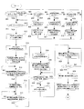
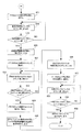
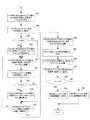
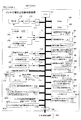
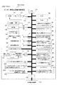
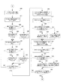
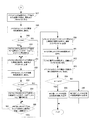
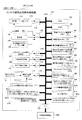
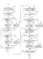
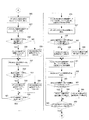
以下、図5〜図9に示したフローチャートに従って、このインキ付着防止性能判断装置100Aおよび印刷機制御装置200における特徴的な動作について説明する。なお、図5〜図7はインキ付着防止性能判断装置100Aで行われる処理を分割して示したフローチャートであり、図8および図9は印刷機制御装置200での処理を分割して示したフローチャートである。
Hereinafter, according to the flowcharts shown in FIGS. 5 to 9, characteristic operations in the ink adhesion prevention
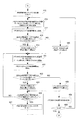
〔ユニット番号、白紙印刷枚数、測定位置情報の入力および設定、画像データの読み取り、保存〕
印刷終了後、インキ付着防止性能判断装置100Aのユニット番号設定器107より検査対象のユニット番号Uを、印刷枚数設定器108より検査に使用する用紙の白紙印刷枚数Nを、測定位置設定器109より検査する用紙の測定位置情報Pとして用紙上の測定位置を入力する。
[Unit number, number of blank pages printed, measurement position information input and setting, image data reading and storage]
After the printing is completed, the unit number U of the object to be inspected by the unit
インキ付着防止性能判断装置100AのCPU101は、ユニット番号設定器107からのユニット番号UをメモリM1に、印刷枚数設定器108からの白紙印刷枚数NをメモリM2に、測定位置設定器109からの測定位置情報PをメモリM3に書き込む(図5に示すステップ301〜310)。
The
この後、スタートスイッチSW1がオンとされると(ステップ311のYES)、CPU101は、メモリM1よりユニット番号Uを、メモリM2より白紙印刷枚数Nを読み出し(ステップ312,313)、印刷機制御装置200に送信する(ステップ314)。
Thereafter, when the start switch SW1 is turned on (YES in step 311), the
印刷機制御装置200のCPU201は、インキ付着防止性能判断装置100Aからのユニット番号Uおよび白紙印刷枚数Nの受信を確認すると(図8に示すステップ801)、その受信したユニット番号Uおよび白紙印刷枚数NをメモリM31およびM32に書き込む(ステップ802)。そして、インキ付着防止性能判断装置100Aに対して、ユニット番号Uおよび白紙印刷枚数Nの受信完了を知らせる(ステップ803)。また、受信したユニット番号Uより胴入れタイミングを演算し、メモリM33に書き込む(ステップ804)。また、受信したユニット番号より胴抜きタイミングを演算し、メモリM34に書き込む(ステップ805)。
When the
インキ付着防止性能判断装置100AのCPU101は、印刷機制御装置200からのユニット番号Uおよび白紙印刷枚数Nの受信完了を確認すると(ステップ315のYES)、印刷機制御装置200へ印刷開始指令を送る(ステップ316)。印刷機制御装置200のCPU201は、インキ付着防止性能判断装置100Aからの印刷開始指令を受信すると(ステップ806のYES)、インキ付着防止性能判断装置100Aに印刷開始指令の受信完了を知らせる(ステップ807)。インキ付着防止性能判断装置100AのCPU101は、印刷機制御装置200からの印刷開始指令の受信完了の知らせを受けて(ステップ317のYES)、メモリM3より測定位置情報Pを読み出す(ステップ318)。そして、この読み出した測定位置情報Pより測定位置に相応する測定位置用カウンタ111のカウント値Cpsを演算し、メモリM4に書き込む(ステップ319)。
When the
一方、印刷機制御装置200のCPU201は、インキ付着防止性能判断装置100Aに印刷開始指令の受信完了の知らせを送った後(ステップ807)、給紙枚数用カウンタ205にリセット信号を送り、給紙枚数用カウンタ205のカウント値を0とする(ステップ808)。そして、給紙装置駆動用回路212に起動指令を送り(ステップ809)、給紙装置211からの印刷機への用紙(白紙)の供給を開始する(ステップ810)。
On the other hand, the
また、CPU201は、メモリM33より胴入れタイミングを読み出し(ステップ811)、回転位相検出用カウンタ210のカウント値が胴入れタイミングとなれば(ステップ813のYES)、メモリM31よりユニット番号Uを読み出す(ステップ814)。そして、この読み出したユニット番号Uによって特定される印刷ユニットの胴着脱装置駆動回路214に着指令信号を出力し(ステップ815)、胴入れを行う。すなわち、その印刷ユニットの圧胴3にゴム胴2を圧接させ、圧胴3とゴム胴2との間を通る用紙に印圧を加える。これにより、搬送中の用紙が圧胴3の周面に装着されている圧胴プレート8の表面に押し付けられる。この際、圧胴プレート8の表面にインキが付着していれば、このインキがその用紙に転写される。また、CPU201は、この胴入れと同時に、胴入れ完了信号をインキ付着防止性能判断装置100Aへ送信する(ステップ816)。
Further, the
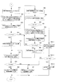
インキ付着防止性能判断装置100AのCPU101は、印刷機制御装置200からの胴入れ完了信号を受信すると(ステップ320のYES)、メモリM4より測定位置に相応する測定位置用カウンタ111のカウント値Cpsを読み出し(ステップ321)、測定位置用カウンタ111の現在のカウント値Cprが測定位置に相応するカウント値Cpsと等しくなれば(ステップ323のYES)、測定器112へ測定指令信号を出力する(ステップ324)。これにより、測定器112中のユニット番号設定器107を介して設定されたカメラ番号のカメラ21が作動し、搬送されてくる用紙の圧胴プレート8に押し付けられた面の一部をその搬送方向にn分割、搬送方向と直交する左右方向にm分割して撮像する。CPU101は、このカメラ21により撮像された画像データZ1−1〜Zn−mをA/D変換器113を介して取り込み、メモリM6に保存する(ステップ325)。
When the
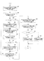
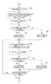
〔画像データの2値化〕
次に、インキ付着防止性能判断装置100AのCPU101は、メモリM7よりスレッシュレベルth1を読み出す(ステップ326)。そして、メモリM6に保存されている最初の画像データZ1−1を読み出し(ステップ327)、この読み出した画像データZ1−1の画素値とスレッシュレベルth1とを比較し(ステップ328)、その画素値がスレッシュレベルth1以上であればメモリM8の該当する画素のアドレスに「1」を書き込み(ステップ329)、スレッシュレベルth1を下回っていればメモリM8の該当する画素のアドレスに「0」を書き込む(ステップ330)。これにより、メモリM8に、2値化された最初の画像データ(2値画像データ)Z1−1’が保存されることになる。
[Binarization of image data]
Next, the
CPU101は、メモリM6に保存されている次の画像データZ2−1についても、最初の画像データZ1−1と同様にして、読み出した画像データZ2−1の画素値とスレッシュレベルth1とを比較し(ステップ332)、その画素値がスレッシュレベルth1以上であればメモリM8の該当する画素のアドレスに「1」を書き込み(ステップ333)、スレッシュレベルth1を下回っていればメモリM8の該当する画素のアドレスに「0」を書き込む(ステップ334)。これにより、メモリM8に、2値化された次の画像データ(2値画像データ)Z2−1’が保存されることになる。以下、ステップ335において、メモリM6内の全ての画像データZ(Z1−1〜Zn−m)の2値化の完了が確認されるまで、ステップ331〜335の処理を繰り返す。
For the next image data Z2-1 stored in the memory M6, the
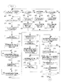
〔ゾーベル微分によるエッジ抽出〕
次に、CPU101は、メモリM8に保存されている最初の2値画像データZ1−1’を読み出し、この2値画像データZ1−1’にゾーベル微分を施し、このゾーベル微分によって得られる2値画像データZ1−1’の画素のゾーベル微分値をメモリM9に記憶する(ステップ336)。ゾーベル微分については、例えば特許文献5に示されているので、ここでの詳しい説明は省略するが、中心画素(対象画素)に対して上下左右の画素に重み付けをして水平微分値と垂直微分値とを得るものとし、|水平微分値|+|垂直微分値|を対象画素のゾーベル微分値とする。
[Edge extraction by Sobel differentiation]
Next, the
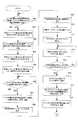
そして、CPU101は、メモリM10よりエッジ判断基準値ethを読み出し(ステップ337)、ステップ336で求めた2値画像データZ1−1’の画素のゾーベル微分値とエッジ判断基準値ethとを比較し(ステップ338)、その画素のゾーベル微分値がエッジ判断基準値eth以上であればメモリM11の該当する画素位置に「1」を書き込み(ステップ339)、エッジ判断基準値ethを下回っていればメモリM11の該当する画素位置に「0」を書き込む(ステップ340)。
The
CPU101は、メモリM8に保存されている次の2値画像データZ2−1’についても、最初の2値画像データZ1−1’と同様にして、2値画像データZ2−1’の画素のゾーベル微分値とエッジ判断基準値ethとを比較し(ステップ343)、その画素のゾーベル微分値がエッジ判断基準値eth以上であればメモリM11の該当する画素位置に「1」を書き込み(ステップ344)、エッジ判断基準値ethを下回っていればメモリM11の該当する画素位置に「0」を書き込む(ステップ345)。以下、ステップ346において、メモリM8内の全ての2値画像データZ’(Z1−1’〜Zn−m’)についてエッジ抽出の完了が確認されるまで、ステップ341〜346の処理作を繰り返す。これにより、2値画像データZ’(Z1−1’〜Zn−m’)中より「1」レベルの画素の各塊の外縁がエッジとして抽出され、このエッジがメモリM11に記憶される。
For the next binary image data Z2-1 ′ stored in the memory M8, the
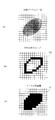
図10(a)に画像データZの一部を示す。各枡目は検出画素である。この画像データZを2値化した各画素にゾーベル微分を施し、エッジ判断基準値ethを用いて「1」,「0」を判定することにより、図10(b)に示すような「1」レベルの画素を連ねたエッジEGが抽出される。 FIG. 10A shows a part of the image data Z. Each cell is a detection pixel. By applying Sobel differentiation to each pixel obtained by binarizing the image data Z and determining “1” and “0” using the edge determination reference value eth, “1” as shown in FIG. 10B is obtained. An edge EG that is a series of level pixels is extracted.
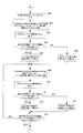
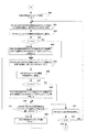
〔インキ付着部の小面積部分のカット〕
次に、CPU101は、メモリM11内の最初のエッジで囲まれた範囲の面積(インキ付着面積)Sを演算し、このインキ付着面積SをメモリM13に記憶する(ステップ347)。すなわち、図10(b)に示したエッジEGについて言えば、このエッジEGで囲まれた範囲の画素の数(図10(c))をカウントし、インキ付着面積(連続してインキが付着した範囲の面積)Sとする。なお、エッジで囲まれた範囲の面積Sは、例えば「Image−ProPLUS((株)プラネトロン)」の解析ソフトを使用して求めることが可能である。
[Cut a small area of the ink adhesion part]
Next, the
そして、メモリM12よりインキ付着部判定面積Sthを読み出し(ステップ348)、この読み出したインキ付着部判定面積Sthとステップ347で求めたインキ付着面積Sとを比較する(ステップ349)。ここで、S<Sthであれば、そのインキ付着面積Sは小面積であると判断し、メモリM11内の最初のエッジで囲まれた範囲のエッジのデータを「1」から「0」に書き替える(ステップ350)。これにより、メモリM11内から最初のエッジで囲まれた範囲のエッジが消え、インキ付着部の小面積部分がカットされる。 Then, the ink adhesion portion determination area Sth is read from the memory M12 (step 348), and the read ink adhesion portion determination area Sth is compared with the ink adhesion area S obtained in step 347 (step 349). Here, if S <Sth, it is determined that the ink adhesion area S is a small area, and the edge data in the range surrounded by the first edge in the memory M11 is written from “1” to “0”. Change (step 350). Thereby, the edge in the range surrounded by the first edge disappears from the memory M11, and the small area portion of the ink adhering portion is cut.
CPU101は、メモリM11に保存されている次のエッジで囲まれた範囲についても、最初のエッジで囲まれた範囲と同様にして、そのエッジで囲まれた範囲の面積Sを演算し(ステップ351)、インキ付着部判定面積Sthと比較し(ステップ353)、S<Sthであれば、メモリM11内の次のエッジで囲まれた範囲のエッジのデータを「1」から「0」に書き替える(ステップ354)。これにより、メモリM11内から次のエッジで囲まれた範囲のエッジが消え、インキ付着部の小面積部分がカットされる。以下、ステップ355において、メモリM11内の全てのエッジで囲まれた範囲について、そのエッジで囲まれた範囲の面積Sの演算が確認されるまで、ステップ351〜355の処理を繰り返す。
For the range surrounded by the next edge stored in the memory M11, the
〔インキ付着防止性能の判断〕
次に、CPU101は、メモリM11内の全てのエッジ(インキ付着部の小面積部分をカットして残されたエッジ)で囲まれた範囲の面積Sを合計し、この合計値STをインキ付着部の合計面積としてメモリM14に格納する(ステップ356)。そして、メモリM15よりインキ付着防止性能判断基準面積STthを読み出し(ステップ357)、この読み出したインキ付着防止性能判断基準面積STthとステップ356で求めたインキ付着部の合計面積STとを比較する(ステップ358)。ここで、ST<STthであれば、表示器105に「インキ付着防止性能問題無し」を表示し(ステップ359)、ST≧STthであれば、表示器105に「インキ付着防止性能問題有り」を表示する(ステップ360)。
[Determination of ink adhesion prevention performance]
Next, the
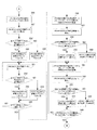
一方、印刷機制御装置200のCPU201は、インキ付着防止性能判断装置100Aへの胴入れ完了信号の送信後(ステップ816)、メモリM32より白紙印刷枚数Nを読み出す(ステップ817)。そして、給紙枚数用カウンタ205のカウント値を読み込み(ステップ818)、この給紙枚数用カウンタ205のカウント値が白紙印刷枚数Nとなれば(ステップ819のYES)、給紙装置駆動用回路212に停止指令を送り(ステップ820)、印刷機への用紙の給紙をストップする。
On the other hand, the
そして、メモリM34より胴抜きタイミングを読み出し(ステップ821)、回転位相検出用カウンタ210のカウント値を読み込んで(ステップ822)、そのカウント値が胴抜きタイミングとなれば(ステップ823のYES)、メモリM31より検査対象のユニット番号Uを読み出し(ステップ824)、このユニット番号Uによって特定される印刷ユニットの胴着脱装置駆動回路214に脱指令信号を送る(ステップ825)。これにより、その印刷ユニットの圧胴3からゴム胴2が離れ、圧胴3に対するゴム胴2の圧接が解除される。
Then, the drum removal timing is read from the memory M34 (step 821), the count value of the rotation
そして、CPU201は、内部クロックカウンタ(測定時間用カウンタ)215のカウント動作を開始し(ステップ826)、メモリM35から停止時の空転時間t1を読み出し(ステップ827)、内部クロックカウンタのカウント値が停止時の空転時間t1となれば(ステップ829のYES)、原動モータドライバ207に停止指令を送り(ステップ830)、原動モータ206をストップし、印刷機の運転を停止する。
Then, the
〔実施の形態2:インキの付着面積率でインキ付着防止性能判断〕
実施の形態1では、インキの付着面積でインキ付着防止性能の判断を行うようにしたが、インキの付着面積率でインキ付着防止性能の判断を行うようにしてもよい。図11にインキの付着面積率でインキ付着防止性能の判断を行うようにした場合のインキ付着防止性能判断装置100Bのブロック図を示す。なお、この実施の形態2や後で説明する実施の形態3〜12において、印刷機制御装置200の構成およびその処理動作は実施の形態1(図4、図8、図9)と同じであるのでその説明は省略する。
[Embodiment 2: Judgment of ink adhesion prevention performance based on ink adhesion area ratio]
In
このインキ付着防止性能判断装置100Bでは、図3に示したインキ付着防止性能判断装置100Aからインキ付着防止性能判断基準面積用のメモリM15をなくし、その代わりにインキ付着防止性能判断基準面積率αthを書き込んだメモリM16を設けている。また、後述する検出エリア内の総面積SATを書き込んだメモリM17と、インキ付着部分の面積率αが書き込まれるメモリM18を設けている。
In this ink adhesion prevention
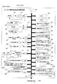
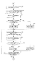
以下、図12〜図14に示したフローチャートに従って、このインキ付着防止性能判断装置100Bにおける特徴的な動作について説明する。なお、図12は図5のフローチャートを、図13は図6のフローチャートを転記したものであり、その処理動作の説明は省略する。また、図14において、ステップ347〜356までの処理は図7に示されたステップ347〜356までの処理と同じである。
Hereinafter, according to the flowcharts shown in FIGS. 12 to 14, characteristic operations in the ink adhesion prevention
〔インキ付着防止性能の判断〕
インキ付着防止性能判断装置100BのCPU101は、メモリM11内の全てのエッジ(インキ付着部の小面積部分をカットして残されたエッジ)で囲まれた範囲の面積Sを合計し、この合計値STをインキ付着部の合計面積としてメモリM14に格納する(ステップ356)。そして、メモリM17より検出エリア内の総面積SATを読み出す(ステップ361)。ここで、検出エリア内の総面積SATとは、画像データZ1−1〜Zn−mの撮像領域の総面積のことを言う。
[Determination of ink adhesion prevention performance]
The
次に、CPU101は、ステップ356で求めたインキ付着部の合計面積STとステップ361で読み出した検出エリア内の総面積SATとから、用紙のインキ付着部分の面積率(インキ付着面積率)αを算出し(α=(ST/SAT)×100)、メモリM18に格納する(ステップ362)。そして、メモリM16からインキ付着防止性能判断基準面積率αthを読み出し(ステップ363)、この読み出したインキ付着防止性能判断基準面積率αthとステップ362で算出したインキ付着面積率αとを比較する(ステップ364)。ここで、α<αthであれば、表示器105に「インキ付着防止性能問題無し」を表示し(ステップ365)、α≧αthであれば、表示器105に「インキ付着防止性能問題有り」を表示する(ステップ366)。
Next, the
〔実施の形態3:インキ付着防止性能判断枚数とインキの付着面積でインキ付着防止性能判断〕
通常、インキの付着面積は、用紙が送られてくる順番に低下する。圧胴プレート8のインキ付着防止性能が高ければ、付着しているインキ量が少ないため、少ない紙枚数でインキの付着面積は低下安定する。これに対し、圧胴プレート8のインキ付着防止性能が低ければ、付着しているインキ量が多いため、インキの付着面積が低下安定するまでには多くの紙枚数を必要とする。
[Embodiment 3: Ink adhesion prevention performance judgment based on the number of ink adhesion prevention performance judgment and ink adhesion area]
Usually, the ink adhesion area decreases in the order in which the sheets are fed. If the performance of the
実施の形態3では、この原理を元に、求めた用紙のインキの付着面積と予め定められている許容面積とを圧胴プレート8に押し付けられた順に比較し、インキの付着面積が許容面積よりも小さくなった最初の用紙の圧胴プレート8に押し付けられた順位(Nx)を求める。そして、この求めた順位と予め定められている許容順位(Nth:インキ付着防止性能判断枚数)とを比較し、求めた順位が許容順位よりも後ろにある場合(Nx>Nth)、圧胴プレート8のインキ付着防止性能が劣化したと判断する。
In the third embodiment, based on this principle, the obtained ink adhesion area of the paper is compared with a predetermined allowable area in the order of pressing against the
図15にインキ付着防止性能判断枚数とインキの付着面積でインキ付着防止性能の判断を行うようにした場合のインキ付着防止性能判断装置100Cのブロック図を示す。
このインキ付着防止性能判断装置100Cでは、図3に示したインキ付着防止性能判断装置100Aの構成に加えて、内部印刷枚数カウンタ121と、インキ付着防止性能判断枚数Nthを書き込んだメモリM19とを設けている。
FIG. 15 shows a block diagram of an ink adhesion prevention performance judging device 100C when the ink adhesion prevention performance judgment is made based on the number of ink adhesion prevention performance judgment sheets and the ink adhesion area.
In addition to the configuration of the ink adhesion prevention
なお、この実施の形態では、説明上、インキ付着防止性能判断枚数Nthを10枚とする。以下、図16〜図22に示したフローチャートに従って、このインキ付着防止性能判断装置100Cにおける特徴的な動作について説明する。
In this embodiment, for the sake of explanation, the number Nth of ink adhesion prevention performance determination is set to 10. Hereinafter, according to the flowcharts shown in FIGS. 16 to 22, characteristic operations in the ink adhesion prevention
〔ユニット番号、白紙印刷枚数、測定位置情報の入力および設定、画像データの読み取り、保存〕
図16において、ステップ301〜317までの処理は図5に示されたステップ301〜317までの処理と同じであるので、その説明は省略する。
インキ付着防止性能判断装置100CのCPU101は、印刷機制御装置200からの印刷開始指令の受信完了の知らせを受けると(ステップ317のYES)、内部印刷枚数カウンタ121のカウント値Nr=0とする(ステップ367)。
そして、メモリM3より測定位置情報Pを読み出し(ステップ368)、この読み出した測定位置情報Pより測定位置に相応する測定位置用カウンタ111のカウント値Cpsを演算し、メモリM4に書き込む(ステップ369)。
[Unit number, number of blank pages printed, measurement position information input and setting, image data reading and storage]
In FIG. 16, the processing from
When the
Then, the measurement position information P is read from the memory M3 (step 368), and the count value Cps of the
印刷機制御装置200からの胴入れ完了信号を受信すると(ステップ370のYES)、メモリM4より測定位置に相応する測定位置用カウンタ111のカウント値Cpsを読み出し(ステップ371)、測定位置用カウンタ111の現在のカウント値Cprが測定位置に相応するカウント値Cpsと等しくなれば(ステップ373のYES)、測定器112へ測定指令信号を出力する(ステップ374)。
When a cylinder insertion completion signal is received from the printing press control apparatus 200 (YES in step 370), the count value Cps of the
これにより、測定器112中のユニット番号設定器107を介して設定されたカメラ番号のカメラ21が作動し、搬送されてくる用紙の圧胴プレート8に押し付けられた面の一部をその搬送方向にn分割、搬送方向と直交する左右方向にm分割して撮像する。CPU101は、このカメラ21により撮像された画像データZ1−1〜Zn−mをA/D変換器113を介して取り込み、メモリM6に保存する(ステップ375)。
As a result, the camera 21 with the camera number set via the unit
そして、内部印刷枚数カウンタ121のカウント値Nrに1を加算し(ステップ376)、メモリM2より白紙印刷枚数Nを読み出し(ステップ377)、この読み出した白紙印刷枚数Nとステップ376で1を加算したカウント値Nrとを比較する(ステップ378)。以下、ステップ378での比較結果がNr=Nとなるまで、ステップ372〜378の処理を繰り返す。これにより、メモリM6には、設定された白紙印刷枚数N枚分の画像データZ1−1〜Zn−mが保存されることになる。
Then, 1 is added to the count value Nr of the internal print sheet counter 121 (step 376), the blank sheet print number N is read from the memory M2 (step 377), and 1 is added to the read blank sheet print number N in
〔画像データの2値化〕
次に、CPU101は、メモリM7よりスレッシュレベルth1を読み出す(ステップ379)。また、内部印刷枚数カウンタ121のカウント値Nrを0とする(ステップ380)。そして、メモリM6に保存されている1枚目の用紙の最初の画像データZ1−1を読み出し(ステップ381)、この読み出した画像データZ1−1の画素値とスレッシュレベルth1とを比較し(ステップ382)、その画素値がスレッシュレベルth1以上であればメモリM8の該当する画素のアドレスに「1」を書き込み(ステップ383)、スレッシュレベルth1を下回っていればメモリM8の該当する画素のアドレスに「0」を書き込む(ステップ384)。これにより、メモリM8に、2値化された1枚目の用紙の最初の画像データ(2値画像データ)Z1−1’が保存されることになる。
[Binarization of image data]
Next, the
CPU101は、メモリM6に保存されている1枚目の用紙の次の画像データZ2−1についても、最初の画像データZ1−1と同様にして、読み出した画像データZ2−1の画素値とスレッシュレベルth1とを比較し(ステップ386)、その画素値がスレッシュレベルth1以上であればメモリM8の該当する画素のアドレスに「1」を書き込み(ステップ387)、スレッシュレベルth1を下回っていればメモリM8の該当する画素のアドレスに「0」を書き込む(ステップ388)。これにより、メモリM8に、2値化された1枚目の用紙の次の画像データ(2値画像データ)Z2−1’が保存されることになる。以下、ステップ389において、メモリM6内の1枚目の用紙の全ての画像データZ(Z1−1〜Zn−m)の2値化の完了が確認されるまで、ステップ385〜389の処理を繰り返す。
As for the next image data Z2-1 of the first sheet stored in the memory M6, the
1枚目の用紙の全ての画像データZ1−1〜Zn−mの2値化が完了すれば(ステップ389のYES)、内部印刷枚数カウンタ121のカウント値Nrに1を加算する(ステップ390)。以下、ステップ402での比較結果がNr=Nとなるまで、1枚目と同様の処理を繰り返す。これにより、メモリM8に、N枚の用紙の全ての2値画像データZ1−1’〜Zn−m’が保存されることになる。
When the binarization of all the image data Z1-1 to Zn-m on the first sheet is completed (YES in step 389), 1 is added to the count value Nr of the internal print number counter 121 (step 390). . Thereafter, the same processing as that of the first sheet is repeated until the comparison result in
〔ゾーベル微分によるエッジ抽出〕
次に、CPU101は、内部印刷枚数カウンタ121のカウント値Nrを0としたうえ(ステップ403)、メモリM8に保存されている1枚目の用紙の最初の2値画像データZ1−1’を読み出し、この2値画像データZ1−1’にゾーベル微分を施し、このゾーベル微分によって得られる2値画像データZ1−1’の画素のゾーベル微分値をメモリM9に記憶する(ステップ404)。
[Edge extraction by Sobel differentiation]
Next, the
そして、メモリM10よりエッジ判断基準値ethを読み出し(ステップ405)、ステップ404で求めた2値画像データZ1−1’の画素のゾーベル微分値とエッジ判断基準値ethとを比較し(ステップ406)、その画素のゾーベル微分値がエッジ判断基準値eth以上であればメモリM11の該当する画素位置に「1」を書き込み(ステップ407)、エッジ判断基準値ethを下回っていればメモリM11の該当する画素位置に「0」を書き込む(ステップ408)。
Then, the edge determination reference value eth is read from the memory M10 (step 405), and the Sobel differential value of the pixel of the binary image data Z1-1 ′ obtained in
CPU101は、メモリM8に保存されている1枚目の用紙の次の2値画像データZ2−1’についても、1枚目の最初の2値画像データZ1−1’と同様にして、2値画像データZ2−1’の画素のゾーベル微分値とエッジ判断基準値ethとを比較し(ステップ411)、その画素のゾーベル微分値がエッジ判断基準値eth以上であればメモリM11の該当する画素位置に「1」を書き込み(ステップ412)、エッジ判断基準値ethを下回っていればメモリM11の該当する画素位置に「0」を書き込む(ステップ413)。以下、ステップ414において、メモリM8内の1枚目の全ての2値画像データZ’(Z1−1’〜Zn−m’)についてエッジ抽出の完了が確認されるまで、ステップ409〜414の処理を繰り返す。これにより、1枚目の用紙の2値画像データZ’(Z1−1’〜Zn−m’)中より「1」レベルの画素の各塊の外縁がエッジとして抽出され、このエッジがメモリM11に記憶される。
The
1枚目の用紙の全ての2値画像データZ1−1’〜Zn−m’についてエッジの抽出が完了すれば(ステップ414のYES)、内部印刷枚数カウンタ121のカウント値Nrに1を加算する(ステップ415)。以下、ステップ429での比較結果がNr=Nとなるまで、1枚目と同様の処理を繰り返す。これにより、メモリM11に、N枚の用紙の全ての2値画像データZ1−1’〜Zn−m’中より抽出されたエッジが記憶されることになる。
When the edge extraction is completed for all the binary image data Z1-1 ′ to Zn-m ′ of the first sheet (YES in step 414), 1 is added to the count value Nr of the internal
〔インキ付着部の小面積部分のカット〕
次に、CPU101は、内部印刷枚数カウンタ121のカウント値Nrを0としたうえ(ステップ430)、メモリM11内の1枚目の用紙の最初のエッジで囲まれた範囲の面積(インキ付着面積)Sを演算し、このインキ付着面積SをメモリM13に記憶する(ステップ431)。そして、メモリM12よりインキ付着部判定面積Sthを読み出し(ステップ432)、この読み出したインキ付着部判定面積Sthとステップ431で求めたインキ付着面積Sとを比較する(ステップ433)。ここで、S<Sthであれば、そのインキ付着面積Sは小面積であると判断し、メモリM11内の1枚目の用紙の最初のエッジで囲まれた範囲のエッジのデータを「1」から「0」に書き替える(ステップ434)。これにより、メモリM11内から1枚目の用紙の最初のエッジで囲まれた範囲のエッジが消え、インキ付着部の小面積部分がカットされる。
[Cut a small area of the ink adhesion part]
Next, the
CPU101は、メモリM11に保存されている1枚目の用紙の次のエッジで囲まれた範囲についても、最初のエッジで囲まれた範囲と同様にして、そのエッジで囲まれた範囲の面積Sを演算し(ステップ435)、インキ付着部判定面積Sthと比較し(ステップ437)、S<Sthであれば、メモリM11内の1枚目の用紙の次のエッジで囲まれた範囲のエッジのデータを「1」から「0」に書き替える(ステップ438)。これにより、メモリM11内から1枚目の用紙の次のエッジで囲まれた範囲のエッジが消え、インキ付着部の小面積部分がカットされる。以下、ステップ439において、メモリM11内の1枚目の用紙の全てのエッジで囲まれた範囲について、そのエッジで囲まれた範囲の面積Sの演算が確認されるまで、ステップ435〜439の処理を繰り返す。
As for the range surrounded by the next edge of the first sheet stored in the memory M11, the
1枚目の用紙の全ての2値画像データZ1−1’〜Zn−m’についてインキ付着部の小面積部分のカット処理が完了すれば(ステップ439のYES)、内部印刷枚数カウンタ121のカウント値Nrに1を加算する(ステップ440)。以下、ステップ452での比較結果がNr=Nとなるまで、1枚目と同様の処理を繰り返す。
When the cut processing of the small area portion of the ink adhering portion has been completed for all the binary image data Z1-1 ′ to Zn-m ′ of the first sheet (YES in step 439), the count of the internal
〔インキ付着防止性能の判断〕
次に、CPU101は、内部印刷枚数カウンタ121のカウント値Nrを0としたうえ(ステップ453)、メモリM11内の1枚目の用紙の全てのエッジ(インキ付着部の小面積部分がカットされた後の残されたエッジ)で囲まれた範囲の面積Sを合計し、この合計値STを1枚目の用紙のインキ付着部の合計面積としてメモリM14に格納する(ステップ454)。そして、メモリM15よりインキ付着防止性能判断基準面積STthを読み出し(ステップ455)、この読み出したインキ付着防止性能判断基準面積STthとステップ454で求めた1枚目の用紙のインキ付着部の合計面積STとを比較する(ステップ456)。
[Determination of ink adhesion prevention performance]
Next, the
ステップ456において、ST<STthであれば、内部印刷枚数カウンタ121のカウント値Nrに1を加算したうえ(ステップ457)、メモリM19よりインキ付着防止性能判断枚数Nthを読み出す(ステップ458)。そして、この読み出したインキ付着防止性能判断枚数Nthとステップ457で1が加算された内部印刷枚数カウンタ121のカウント値Nrとを比較し、Nr≦Nthであれば(ステップ459のYES)、表示器105に「インキ付着防止性能問題無し」を表示し(ステップ460)、Nr>Nthであれば(ステップ459のNO)、表示器105に「インキ付着防止性能問題有り」を表示する(ステップ461)。
In
この実施の形態では、インキ付着防止性能判断枚数Nthを10枚としているので、ステップ456で1枚目の用紙のインキ付着部の合計面積STがSTth以下と判断されれば、表示器105には直ちに「インキ付着防止性能問題無し」と表示される(図23(a)参照)。
In this embodiment, since the number Nth of the ink adhesion prevention performance determination is 10, the
ステップ456において、ST≧STthであれば、内部印刷枚数カウンタ121のカウント値Nrに1を加算したうえ(ステップ462)、メモリM2より白紙印刷枚数Nを読み出し(ステップ463)、読み出した白紙印刷枚数Nと内部印刷枚数カウンタ121のカウント値Nrとを比較する(ステップ464)。
In
内部印刷枚数カウンタ121のカウント値Nr、すなわち現在の用紙の印刷枚数Nrが白紙印刷枚数Nに達していなければ(ステップ464のYES)、CPU101は、メモリM11内の次の用紙の全てのエッジで囲まれた範囲の面積Sを合計し、この合計値STをインキ付着部の合計面積としてメモリM14に格納する(ステップ465)。そして、メモリM15よりインキ付着防止性能判断基準面積STthを読み出し(ステップ466)、この読み出したインキ付着防止性能判断基準面積STthとステップ465で求めたインキ付着部の合計面積STとを比較する(ステップ467)。
If the count value Nr of the internal
ステップ467において、ST≧STthであればステップ462へ戻って、ステップ462〜467の処理を繰り返す。ステップ467において、ST<STthとなれば、内部印刷枚数カウンタ121のカウント値Nrに1を加算したうえ(ステップ468)、メモリM19よりインキ付着防止性能判断枚数Nthを読み出す(ステップ458)。
In
そして、この読み出したインキ付着防止性能判断枚数Nthとステップ468で1が加算された内部印刷枚数カウンタ121のカウント値Nrとを比較し、Nr≦Nthであれば(ステップ459のYES)、表示器105に「インキ付着防止性能問題無し」を表示し(ステップ460)、Nr>Nthであれば(ステップ459のNO)、表示器105に「インキ付着防止性能問題有り」を表示する(ステップ461)。
Then, the read ink adhesion prevention performance determination number Nth is compared with the count value Nr of the internal
この実施の形態では、インキ付着防止性能判断枚数Nthを10枚としているので、ステップ467でST<STthとされた用紙の印刷枚数Nrが10枚以内であれば、すなわちその用紙の印刷順位が10番以内であれば、表示器105には「インキ付着防止性能問題無し」と表示される(図23(b)参照)。これに対して、ステップ467でST<STthとされた用紙の印刷枚数Nrが10枚を超えると、すなわちその用紙の印刷順位がインキ付着防止性能判断枚数Nthよりも後ろとなると、表示器105には「インキ付着防止性能問題有り」と表示される(図23(c)参照)。
In this embodiment, since the number Nth of ink adhesion prevention performance determination is set to 10, if ST <STth, the number of printed sheets Nr is less than 10 in
なお、この実施の形態3において、ST<STthが確認されないまま、内部印刷枚数カウンタ121のカウント値Nrが白紙印刷枚数Nに達すると(ステップ464のNO)、CPU101は、メモリM19よりインキ付着防止性能判断枚数Nthを読み出し(ステップ469−1)、Nr<Nthではないことを確認のうえ(ステップ469−2のNO)、表示器105に「インキ付着防止性能問題あり」を表示する(ステップ461:図23(d)参照)。また、ステップ469−2でNr<Nthであることが確認されれば、表示器105に「判断不可能」を表示する(ステップ469−3:図23(e)参照)。
In the third embodiment, when the count value Nr of the internal
〔実施の形態4:インキ付着防止性能判断枚数とインキの付着面積率でインキ付着防止性能判断〕
実施の形態3では、インキ付着防止性能判断枚数とインキの付着面積でインキ付着防止性能の判断を行うようにしたが、インキ付着防止性能判断枚数とインキの付着面積率でインキ付着防止性能の判断を行うようにしてもよい。図24にインキ付着防止性能判断枚数とインキの付着面積率でインキ付着防止性能の判断を行うようにした場合のインキ付着防止性能判断装置100Dのブロック図を示す。
[Embodiment 4: Ink adhesion prevention performance judgment based on the number of ink adhesion prevention performance judgment sheets and ink adhesion area ratio]
In the third embodiment, the ink adhesion prevention performance is judged based on the number of ink adhesion prevention performance judgments and the ink adhesion area, but the ink adhesion prevention performance judgment is based on the ink adhesion prevention performance judgment number and the ink adhesion area ratio. May be performed. FIG. 24 shows a block diagram of an ink adhesion prevention
このインキ付着防止性能判断装置100Dでは、図15に示したインキ付着防止性能判断装置100Cからインキ付着防止性能判断基準面積用のメモリM15をなくし、その代わりにインキ付着防止性能判断基準面積率αthを書き込んだメモリM16を設けている。また、検出エリア内の総面積SATを書き込んだメモリM17と、インキ付着面積率αが書き込まれるメモリM18を設けている。なお、この実施の形態においても、インキ付着防止性能判断枚数Nthは10枚とする。
In this ink adhesion prevention
以下、図25〜図31に示したフローチャートに従って、インキ付着防止性能判断装置100Dにおける特徴的な動作について説明する。なお、図25は図16のフローチャートを、図26は図17のフローチャートを、図27は図18のフローチャートを、図28は図19のフローチャートを、図29は図20のフローチャートを、図30は図21のフローチャートを転記したものであり、その処理の説明は省略する。
Hereinafter, according to the flowcharts shown in FIGS. 25 to 31, characteristic operations in the ink adhesion prevention
〔インキ付着防止性能の判断〕
CPU101は、内部印刷枚数カウンタ121のカウント値Nrを0としたうえ(ステップ453)、メモリM11内の1枚目の用紙の全てのエッジで囲まれた範囲の面積Sを合計し、この合計値STを1枚目の用紙のインキ付着部の合計面積としてメモリM14に格納する(ステップ454)。そして、メモリM17より検出エリア内の総面積SATを読み出す(ステップ470)。
[Determination of ink adhesion prevention performance]
The
次に、CPU101は、ステップ454で求めた1枚目の用紙のインキ付着部の合計面積STとステップ470で読み出した検出エリア内の総面積SATとから、1枚目の用紙のインキ付着面積率αを算出し(α=(ST/SAT)×100)、メモリM18に格納する(ステップ471)。そして、メモリM16からインキ付着防止性能判断基準面積率αthを読み出し(ステップ472)、この読み出したインキ付着防止性能判断基準面積率αthとステップ471で算出した1枚目の用紙のインキ付着面積率αとを比較する(ステップ473)。
Next, the
ステップ473において、α<αthであれば、内部印刷枚数カウンタ121のカウント値Nrに1を加算したうえ(ステップ474)、メモリM19よりインキ付着防止性能判断枚数Nthを読み出す(ステップ475)。そして、この読み出したインキ付着防止性能判断枚数Nthとステップ474で1が加算された内部印刷枚数カウンタ121のカウント値Nrとを比較し、Nr≦Nthであれば(ステップ476のYES)、表示器105に「インキ付着防止性能問題無し」を表示し(ステップ477)、Nr>Nthであれば(ステップ476のNO)、表示器105に「インキ付着防止性能問題有り」を表示する(ステップ478)。
If α <αth in
この実施の形態では、インキ付着防止性能判断枚数Nthを10枚としているので、ステップ473で1枚目の用紙のインキ付着面積率αがαth以下と判断されれば、表示器105には直ちに「インキ付着防止性能問題無し」と表示される(図32(a)参照)。
In this embodiment, since the number Nth of ink adhesion prevention performance determination is set to 10, if it is determined in
ステップ473において、α≧αthであれば、内部印刷枚数カウンタ121のカウント値Nrに1を加算したうえ(ステップ479)、メモリM2より白紙印刷枚数Nを読み出し(ステップ480)、読み出した白紙印刷枚数Nと内部印刷枚数カウンタ121のカウント値Nrとを比較する(ステップ481)。
In
内部印刷枚数カウンタ121のカウント値Nr、すなわち現在の用紙の印刷枚数Nrが設定されている白紙印刷枚数Nに達していなければ(ステップ481のYES)、CPU101は、メモリM11内の次の用紙の全てのエッジで囲まれた範囲の面積Sを合計し、この合計値STをインキ付着部の合計面積としてメモリM14に格納する(ステップ482)。
If the count value Nr of the internal
そして、メモリM17より検出エリア内の総面積SATを読み出し(ステップ483)、ステップ482で求めた次の用紙のインキ付着部の合計面積とステップ483で読み出した検出エリア内の総面積SATとから、次の用紙のインキ付着面積率αを算出し(α=(ST/SAT)×100)、メモリM18に格納する(ステップ484)。そして、メモリM16からインキ付着防止性能判断基準面積率αthを読み出し(ステップ485)、この読み出したインキ付着防止性能判断基準面積率αthとステップ484で算出した次の用紙のインキ付着面積率αとを比較する(ステップ486)。
Then, the total area SAT in the detection area is read from the memory M17 (step 483). From the total area of the ink adhering portion of the next sheet obtained in
ステップ486において、α≧αthであればステップ479へ戻って、ステップ479〜486の処理を繰り返す。ステップ486において、α<αthとなれば、内部印刷枚数カウンタ121のカウント値Nrに1を加算したうえ(ステップ487)、メモリM19よりインキ付着防止性能判断枚数Nthを読み出す(ステップ475)。そして、この読み出したインキ付着防止性能判断枚数Nthとステップ487で1が加算された内部印刷枚数カウンタ121のカウント値Nrとを比較し、Nr≦Nthであれば(ステップ476のYES)、表示器105に「インキ付着防止性能問題無し」を表示し(ステップ477)、Nr>Nthであれば(ステップ476のNO)、表示器105に「インキ付着防止性能問題有り」を表示する(ステップ478)。
In
この実施の形態では、インキ付着防止性能判断枚数Nthを10枚としているので、ステップ486でα<αthとされた用紙の印刷枚数Nrが10枚以内であれば、すなわちその用紙の印刷順位が10番以内であれば、表示器105には「インキ付着防止性能問題無し」と表示される(図32(b)参照)。これに対して、ステップ486でα<αthとされた用紙の印刷枚数Nrが10枚を超えると、すなわちその用紙の印刷順位がインキ付着防止性能判断枚数Nthよりも後ろとなると、表示器105には「インキ付着防止性能問題有り」と表示される(図32(c)参照)。
In this embodiment, since the number Nth of the ink adhesion prevention performance determination is set to 10, if the number Nr of printed sheets for which α <αth in
なお、この実施の形態4において、α<αthが確認されないまま、内部印刷枚数カウンタ121のカウント値Nrが白紙印刷枚数Nに達すると(ステップ481のNO)、CPU101は、メモリM19よりインキ付着防止性能判断枚数Nthを読み出し(ステップ488−1)、Nr<Nthではないことを確認のうえ(ステップ488−2のNO)、表示器105に「インキ付着防止性能問題あり」を表示する(ステップ478:図32(d)参照)。また、ステップ488−2でNr<Nthであることが確認されれば、表示器105に「判断不可能」を表示する(ステップ488−3:図32(e)参照)。
In the fourth embodiment, when the count value Nr of the internal
〔実施の形態5:N枚目の用紙のインキの付着面積でインキ付着防止性能判断〕
実施の形態1では、1枚目の用紙(最初の用紙)のインキの付着面積でインキ付着防止性能の判断が行われるが、N枚目の用紙(最後の用紙)のインキの付着面積でインキ付着防止性能の判断を行うようにしてもよい。
[Embodiment 5: Ink adhesion prevention performance judgment based on ink adhesion area of Nth sheet]
In the first embodiment, the ink adhesion prevention performance is determined by the ink adhesion area of the first sheet (first sheet), but the ink adhesion area of the Nth sheet (last sheet) is determined by the ink adhesion area. You may make it judge adhesion prevention performance.
図33にN枚目の用紙のインキの付着面積でインキ付着防止性能の判断を行うようにした場合のインキ付着防止性能判断装置100Eのブロック図を示す。このインキ付着防止性能判断装置100Eでは、図3に示したインキ付着防止性能判断装置100Aの構成に加えて、内部印刷枚数カウンタ121を設けている。図34〜図36にこのインキ付着防止性能判断装置100Eの処理フローを示す。なお、図35は図6のフローチャートを、図36は図7のフローチャートを転記したものであり、その処理の説明は省略する。また、図34において、ステップ301〜317までの処理は図5に示されたステップ301〜317までの処理と同じである。
FIG. 33 shows a block diagram of the ink adhesion prevention
インキ付着防止性能判断装置100EのCPU101は、印刷機制御装置200からの印刷開始指令の受信完了の知らせを受けると(ステップ317のYES)、内部印刷枚数カウンタ121のカウント値Nr=0とする(ステップ490)。そして、メモリM3より測定位置情報Pを読み出し(ステップ491)、この読み出した測定位置情報Pより測定位置に相応する測定位置用カウンタ111のカウント値Cpsを演算し、メモリM4に書き込む(ステップ492)。
When the
印刷機制御装置200からの胴入れ完了信号を受信すると(ステップ493のYES)、メモリM4より測定位置に相応する測定位置用カウンタ111のカウント値Cpsを読み出し(ステップ494)、測定位置用カウンタ111の現在のカウント値Cprが測定位置に相応するカウント値Cpsと等しくなれば(ステップ496のYES)、内部印刷枚数カウンタ121のカウント値Nrに1を加算する(ステップ497)。そして、メモリM2より白紙印刷枚数Nを読み出し(ステップ498)、読み出した白紙印刷枚数Nと内部印刷枚数カウンタ121のカウント値Nrとを比較する(ステップ499)。
When a cylinder insertion completion signal is received from the printing press controller 200 (YES in step 493), the count value Cps of the
そして、内部印刷枚数カウンタ121のカウント値Nr、すなわち現在の用紙の印刷枚数Nrが白紙印刷枚数Nに達するまでステップ495〜499の処理を繰り返す。現在の用紙の印刷枚数Nrが白紙印刷枚数Nに達すると(ステップ499のYES)、測定器112へ測定指令信号を出力する(ステップ500)。これにより、ユニット番号設定器107を介して設定されたカメラ番号のカメラ21が作動し、搬送されてくるN枚目の用紙(最後の用紙)の圧胴プレート8に押し付けられた面の一部をその搬送方向にn分割、搬送方向と直交する左右方向にm分割して撮像する。CPU101は、このカメラ21により撮像された画像データZ1−1〜Zn−mをA/D変換器113を介して取り込み、メモリM6に保存する(ステップ501)。
Then, the processes of
尚、この実施の形態5では、検査対象の用紙を白紙印刷枚数Nの最後の用紙としたが、別に検査対象用紙の順位を決める設定器を設け、その設定器の設定を白紙印刷枚数Nより小さい数とし、余分に白紙を供給するようにしても同じ効果が得られることは、言うまでもない。 In the fifth embodiment, the sheet to be inspected is the last sheet with the number N of blank pages printed. However, a setting device for determining the order of the sheets to be inspected is provided, and the setting device is set according to the number N of blank sheets to be printed. It goes without saying that the same effect can be obtained even if a small number is used and extra blank paper is supplied.
〔実施の形態6:N枚目の用紙のインキの付着面積率でインキ付着防止性能判断〕
実施の形態5では、N枚目の用紙のインキの付着面積でインキ付着防止性能の判断を行うようにしたが、N枚目の用紙のインキの付着面積率でインキ付着防止性能の判断を行うようにしてもよい。
[Embodiment 6: Ink adhesion prevention performance judgment based on ink adhesion area ratio of Nth sheet]
In the fifth embodiment, the ink adhesion prevention performance is determined by the ink adhesion area of the Nth sheet, but the ink adhesion prevention performance is determined by the ink adhesion area ratio of the Nth sheet. You may do it.
図37にN枚目の用紙のインキの付着面積率でインキ付着防止性能の判断を行うようにした場合のインキ付着防止性能判断装置100Fのブロック図を示す。このインキ付着防止性能判断装置100Fでは、図11に示したインキ付着防止性能判断装置100Bの構成に加えて、内部印刷枚数カウンタ121を設けている。図38〜図40にこのインキ付着防止性能判断装置100Fの処理フローを示す。なお、図38は図34のフローチャートを、図39は図13のフローチャートを、図40は図14のフローチャートを転記したものであり、その処理動作の説明は省略する。
FIG. 37 shows a block diagram of the ink adhesion preventing
尚、この実施の形態6では、検査対象の用紙を白紙印刷枚数Nの最後の用紙としたが、別に検査対象用紙の順位を決める設定器を設け、その設定器の設定を白紙印刷枚数Nより小さい数とし、余分に白紙を供給するようにしても同じ効果が得られることは、言うまでもない。 In the sixth embodiment, the sheet to be inspected is the last sheet of the number N of blank pages to be printed. However, a setting device for determining the order of the sheets to be inspected is provided separately. It goes without saying that the same effect can be obtained even if a small number is used and extra blank paper is supplied.
〔実施の形態7:インキの非付着面積でインキ付着防止性能判断〕
上述した実施の形態1では、インキの付着面積でインキ付着防止性能の劣化を判断するようにしたが、インキの非付着面積でインキ付着防止性能の劣化を判断するようにしてもよい。図41にインキの非付着面積でインキ付着防止性能の劣化を判断するようにしたインキ付着防止性能判断装置100Gのブロック図を示す。
[Embodiment 7: Ink adhesion prevention performance judgment based on non-adhesion area of ink]
In the first embodiment described above, the deterioration of the ink adhesion prevention performance is determined based on the ink adhesion area, but the deterioration of the ink adhesion prevention performance may be determined based on the non-ink adhesion area. FIG. 41 shows a block diagram of an ink adhesion prevention
このインキ付着防止性能判断装置100Gは、図3に示したインキ付着防止性能判断装置100Aと同構成であるが、メモリM14には「エッジ用メモリ内のすべてのエッジで囲まれた範囲の面積の合計」ではなく、「2値化された画像データ用メモリ内の「1」レベルの画素の面積の合計」を記憶させる。図42〜図44にこのインキ付着防止性能判断装置100Gの処理フローを示す。
This ink adhesion prevention
この実施の形態7において、CPU101は、ステップ328’,332’で画像データZの画素値をチェックし、その画素値がスレッシュレベルth1以下であればメモリM8の該当する画素のアドレスに「1」を書き込み(ステップ329,333)、スレッシュレベルth1を上回っていればメモリM8の該当する画素のアドレスに「0」を書き込む(ステップ330,334)。これにより、メモリM8に、その画素値がスレッシュレベルth1以下の画素、すなわちインキが付着していないと判断される画素を「1」とする2値画像データZ’(Z1−1’〜Zn−m’)が保存される。
In the seventh embodiment, the
次に、CPU101は、このメモリM8に保存した2値画像データZ’(Z1−1’〜Zn−m’)に対し、ゾーベル微分によるエッジ抽出を行う(ステップ336〜346)。これにより、2値画像データZ’(Z1−1’〜Zn−m’)中より「1」レベルの画素の各塊の外縁がエッジとして抽出され、このエッジがメモリM11に記憶される。
Next, the
そして、CPU101は、このメモリM11内の最初のエッジで囲まれた範囲の面積Sを演算し、この面積SをメモリM13に記憶する(ステップ347)。そして、メモリM12よりインキ付着部判定面積Sthを読み出し(ステップ348)、この読み出したインキ付着部判定面積Sthとステップ347で求めた面積Sとを比較する(ステップ349)。ここで、S<Sthであれば、その面積Sは小面積であると判断し、最初のエッジで囲まれている範囲に相当する範囲のメモリM8内のデータを「0」から「1」に書き替える(ステップ350’)。これにより、メモリM8に「1」レベルのデータとして、小面積と判断された最初のエッジで囲まれた範囲に相当する範囲の面積(小面積と判断されたインキ付着部分の面積)がインキ非付着部分の面積として追加される。
Then, the
CPU101は、メモリM11に保存されている次のエッジで囲まれた範囲についても、最初のエッジで囲まれた範囲と同様にして、そのエッジで囲まれた範囲の面積Sを演算し(ステップ351)、インキ付着部判定面積Sthと比較し(ステップ353)、S<Sthであれば、その面積Sは小面積であると判断し、次のエッジで囲まれている範囲に相当する範囲のメモリM8内のデータを「0」から「1」に書き替える(ステップ354’)。以下、ステップ355において、メモリM11内の全てのエッジで囲まれた範囲について、そのエッジで囲まれた範囲の面積Sの演算が確認されるまで、ステップ351〜355の処理を繰り返す。
For the range surrounded by the next edge stored in the memory M11, the
次に、CPU101は、メモリM8内の「1」レベルの画素の面積を合計し、この合計値STをインキ非付着部の合計面積としてメモリM14に格納する(ステップ356’)。そして、メモリM15よりインキ付着防止性能判断基準面積STthを読み出し(ステップ357)、この読み出したインキ付着防止性能判断基準面積STthとステップ356’で求めたインキ非付着部の合計面積STとを比較する(ステップ358’)。ここで、ST>STthであれば、表示器105に「インキ付着防止性能問題無し」を表示し(ステップ359)、ST≦STthであれば、表示器105に「インキ付着防止性能問題有り」を表示する(ステップ360)。
Next, the
〔実施の形態8:インキの非付着面積率でインキ付着防止性能判断〕
実施の形態7では、インキの非付着面積でインキ付着防止性能の判断を行うようにしたが、インキの非付着面積率でインキ付着防止性能の判断を行うようにしてもよい。図45にインキの非付着面積率でインキ付着防止性能の判断を行うようにした場合のインキ付着防止性能判断装置100Hのブロック図を示す。
[Embodiment 8: Ink adhesion prevention performance judgment based on ink non-adhesion area ratio]
In the seventh embodiment, the ink adhesion prevention performance is determined based on the ink non-adhesion area. However, the ink adhesion prevention performance may be determined based on the ink non-adhesion area ratio. FIG. 45 shows a block diagram of the ink adhesion preventing
このインキ付着防止性能判断装置100Hは、図11に示したインキ付着防止性能判断装置100Bと同構成であるが、メモリM14には「エッジ用メモリ内のすべてのエッジで囲まれた範囲の面積の合計」ではなく、「2値化された画像データ用メモリ内の「1」レベルの画素の面積の合計」を記憶させる。また、メモリM18にはインキ付着部分の面積率ではなく、インキ非付着部分の面積率αを書き込むようにする。図46〜図48にこのインキ付着防止性能判断装置100Hの処理フローを示す。
The ink adhesion prevention
この実施の形態8において、CPU101は、ステップ356’で求めたインキ非付着部の合計面積STとステップ361で読み出した検出エリア内の総面積SATとから、用紙のインキ非付着部分の面積率(インキ非付着面積率)αを算出し(α=(ST/SAT)×100)、メモリM18に格納する(ステップ362)。そして、メモリM16からインキ付着防止性能判断基準面積率αthを読み出し(ステップ363)、この読み出したインキ付着防止性能判断基準面積率αthとステップ362で算出したインキ非付着面積率αとを比較する(ステップ364’)。ここで、α>αthであれば、表示器105に「インキ付着防止性能問題無し」を表示し(ステップ365)、α≦αthであれば、表示器105に「インキ付着防止性能問題有り」を表示する(ステップ366)。
In the eighth embodiment, the
〔実施の形態9:インキ付着防止性能判断枚数とインキの非付着面積でインキ付着防止性能判断〕
図49にインキ付着防止性能判断枚数とインキの非付着面積でインキ付着防止性能の判断を行うようにした場合のインキ付着防止性能判断装置100Iのブロック図を示す。
このインキ付着防止性能判断装置100Iは、図15に示したインキ付着防止性能判断装置100Cと同構成であるが、メモリM14には「エッジ用メモリ内のすべてのエッジで囲まれた範囲の面積の合計」ではなく、「2値化された画像データ用メモリ内の「1」レベルの画素の面積の合計」を記憶させる。図50〜図56にこのインキ付着防止性能判断装置100Iの処理フローを示す。
[Embodiment 9: Ink adhesion prevention performance judgment based on the number of ink adhesion prevention performance judgment sheets and the non-adhesion area of ink]
FIG. 49 shows a block diagram of the ink adhesion prevention performance judging device 100I when the ink adhesion prevention performance judgment is made based on the number of ink adhesion prevention performance judgment sheets and the non-adhesion area of the ink.
This ink adhesion prevention performance judgment device 100I has the same configuration as the ink adhesion prevention performance judgment device 100C shown in FIG. 15, but the memory M14 has an “area within the range surrounded by all edges in the edge memory. Instead of “total”, “total of areas of“ 1 ”level pixels in the binarized image data memory” is stored. 50 to 56 show the processing flow of the ink adhesion prevention performance judging device 100I.
この実施の形態9において、CPU101は、メモリM8内の1枚目の用紙の「1」レベルの画素の面積を合計し、この合計値STを1枚目の用紙のインキ非付着部の合計面積としてメモリM14に格納する(ステップ454’)。そして、メモリM15よりインキ付着防止性能判断基準面積STthを読み出し(ステップ455)、この読み出したインキ付着防止性能判断基準面積STthとステップ454’で求めた1枚目の用紙のインキ非付着部の合計面積STとを比較する(ステップ456’)。
In the ninth embodiment, the
ステップ456’において、ST>STthであれば、内部印刷枚数カウンタ121のカウント値Nrに1を加算したうえ(ステップ457)、メモリM19よりインキ付着防止性能判断枚数Nthを読み出す(ステップ458)。そして、この読み出したインキ付着防止性能判断枚数Nthとステップ457で1が加算された内部印刷枚数カウンタ121のカウント値Nrとを比較し、Nr≦Nthであれば(ステップ459のYES)、表示器105に「インキ付着防止性能問題無し」を表示し(ステップ460)、Nr>Nthであれば(ステップ459のNO)、表示器105に「インキ付着防止性能問題有り」を表示する(ステップ461)。
In step 456 ', if ST> STth, 1 is added to the count value Nr of the internal print sheet counter 121 (step 457), and the ink adhesion prevention performance determination sheet number Nth is read from the memory M19 (step 458). Then, the read ink adhesion prevention performance determination number Nth is compared with the count value Nr of the internal
ステップ456’において、ST≦STthであれば、内部印刷枚数カウンタ121のカウント値Nrに1を加算したうえ(ステップ462)、メモリM2より白紙印刷枚数Nを読み出し(ステップ463)、読み出した白紙印刷枚数Nと内部印刷枚数カウンタ121のカウント値Nrとを比較する(ステップ464)。
In
内部印刷枚数カウンタ121のカウント値Nr、すなわち現在の用紙の印刷枚数Nrが白紙印刷枚数Nに達していなければ(ステップ464のYES)、CPU101は、メモリM8内の次の用紙の「1」レベルの画素の面積を合計し、この合計値STを次の用紙のインキ非付着部の合計面積としてメモリM14に格納する(ステップ465’)。そして、メモリM15よりインキ付着防止性能判断基準面積STthを読み出し(ステップ466)、この読み出したインキ付着防止性能判断基準面積STthとステップ465’で求めたインキ非付着部の合計面積STとを比較する(ステップ467’)。
If the count value Nr of the internal
ステップ467’において、ST≦STthであればステップ462へ戻って、ステップ462〜467’の処理を繰り返す。ステップ467’において、ST>STthとなれば、内部印刷枚数カウンタ121のカウント値Nrに1を加算したうえ(ステップ468)、メモリM19よりインキ付着防止性能判断枚数Nthを読み出す(ステップ458)。
In step 467 ', if ST≤STth, the process returns to step 462, and the processes in
そして、この読み出したインキ付着防止性能判断枚数Nthとステップ468で1が加算された内部印刷枚数カウンタ121のカウント値Nrとを比較し、Nr≦Nthであれば(ステップ459のYES)、表示器105に「インキ付着防止性能問題無し」を表示し(ステップ460)、Nr>Nthであれば(ステップ459のNO)、表示器105に「インキ付着防止性能問題有り」を表示する(ステップ461)。
Then, the read ink adhesion prevention performance determination number Nth is compared with the count value Nr of the internal
なお、この実施の形態9において、ST>STthが確認されないまま、内部印刷枚数カウンタ121のカウント値Nrが白紙印刷枚数Nに達すると(ステップ464のNO)、CPU101は、メモリM19よりインキ付着防止性能判断枚数Nthを読み出し(ステップ469−1)、Nr<Nthではないことを確認のうえ(ステップ469−2のNO)、表示器105に「インキ付着防止性能問題あり」を表示する(ステップ461)。また、ステップ469−2でNr<Nthであることが確認されれば、表示器105に「判断不可能」を表示する(ステップ469−3)。
In the ninth embodiment, when the count value Nr of the internal
〔実施の形態10:インキ付着防止性能判断枚数とインキの非付着面積率でインキ付着防止性能判断〕
実施の形態9では、インキ付着防止性能判断枚数とインキの非付着面積でインキ付着防止性能の判断を行うようにしたが、インキ付着防止性能判断枚数とインキの非付着面積率でインキ付着防止性能の判断を行うようにしてもよい。図57にインキ付着防止性能判断枚数とインキの非付着面積率でインキ付着防止性能の判断を行うようにした場合のインキ付着防止性能判断装置100Jのブロック図を示す。
[Embodiment 10: Ink adhesion prevention performance judgment based on the number of ink adhesion prevention performance judgment sheets and the non-adhesion area ratio of ink]
In the ninth embodiment, the ink adhesion prevention performance is judged based on the number of ink adhesion prevention performance judgments and the ink non-adhesion area, but the ink adhesion prevention performance is judged based on the ink adhesion prevention performance judgment number and the ink non-adhesion area ratio. You may make it judge. FIG. 57 shows a block diagram of the ink adhesion prevention
このインキ付着防止性能判断装置100Jは、図24に示したインキ付着防止性能判断装置100Dと同構成であるが、メモリM14には「エッジ用メモリ内のすべてのエッジで囲まれた範囲の面積の合計」ではなく、「2値化された画像データ用メモリ内の「1」レベルの画素の面積の合計」を記憶させる。また、メモリM18にはインキ付着部分の面積率ではなく、インキ非付着部分の面積率αを書き込むようにする。図58〜図64にこのインキ付着防止性能判断装置100Jの処理フローを示す。
The ink adhesion prevention
この実施の形態10において、CPU101は、メモリM8内の1枚目の用紙の「1」レベルの画素の面積を合計し、この合計値STを1枚目の用紙のインキ非付着部の合計面積としてメモリM14に格納する(ステップ454’)。そして、メモリM17より検出エリア内の総面積SATを読み出す(ステップ470)。
In the tenth embodiment, the
次に、CPU101は、ステップ454’で求めた1枚目の用紙のインキ非付着部の合計面積STとステップ470で読み出した検出エリア内の総面積SATとから、1枚目の用紙のインキ非付着面積率αを算出し(α=(ST/SAT)×100)、メモリM18に格納する(ステップ471)。そして、メモリM16からインキ付着防止性能判断基準面積率αthを読み出し(ステップ472)、この読み出したインキ付着防止性能判断基準面積率αthとステップ471で算出した1枚目の用紙のインキ非付着面積率αとを比較する(ステップ473’)。
Next, the
ステップ473’において、α>αthであれば、内部印刷枚数カウンタ121のカウント値Nrに1を加算したうえ(ステップ474)、メモリM19よりインキ付着防止性能判断枚数Nthを読み出す(ステップ475)。そして、この読み出したインキ付着防止性能判断枚数Nthとステップ474で1が加算された内部印刷枚数カウンタ121のカウント値Nrとを比較し、Nr≦Nthであれば(ステップ476のYES)、表示器105に「インキ付着防止性能問題無し」を表示し(ステップ477)、Nr>Nthであれば(ステップ476のNO)、表示器105に「インキ付着防止性能問題有り」を表示する(ステップ478)。
If α> αth in
ステップ473’において、α≦αthであれば、内部印刷枚数カウンタ121のカウント値Nrに1を加算したうえ(ステップ479)、メモリM2より白紙印刷枚数Nを読み出し(ステップ480)、読み出した白紙印刷枚数Nと内部印刷枚数カウンタ121のカウント値Nrとを比較する(ステップ481)。
If α ≦ αth in
内部印刷枚数カウンタ121のカウント値Nr、すなわち現在の用紙の印刷枚数Nrが設定されている白紙印刷枚数Nに達していなければ(ステップ481のYES)、CPU101は、メモリM8内の次の用紙の「1」レベルの画素の面積を合計し、この合計値STを次の用紙のインキ非付着部の合計面積としてメモリM14に格納する(ステップ482’)。
If the count value Nr of the internal
そして、メモリM17より検出エリア内の総面積SATを読み出し(ステップ483)、ステップ482’で求めた次の用紙のインキ非付着部の合計面積とステップ483で読み出した検出エリア内の総面積SATとから、次の用紙のインキ非付着面積率αを算出し(α=(ST/SAT)×100)、メモリM18に格納する(ステップ484)。そして、メモリM16からインキ付着防止性能判断基準面積率αthを読み出し(ステップ485)、この読み出したインキ付着防止性能判断基準面積率αthとステップ484で算出した次の用紙のインキ非付着面積率αとを比較する(ステップ486’)。
Then, the total area SAT in the detection area is read from the memory M17 (step 483), the total area of the non-ink-attached portion of the next sheet obtained in
ステップ486’において、α≦αthであればステップ479へ戻って、ステップ479〜486’の処理を繰り返す。ステップ486’において、α>αthとなれば、内部印刷枚数カウンタ121のカウント値Nrに1を加算したうえ(ステップ487)、メモリM19よりインキ付着防止性能判断枚数Nthを読み出す(ステップ475)。そして、この読み出したインキ付着防止性能判断枚数Nthとステップ487で1が加算された内部印刷枚数カウンタ121のカウント値Nrとを比較し、Nr≦Nthであれば(ステップ476のYES)、表示器105に「インキ付着防止性能問題無し」を表示し(ステップ477)、Nr>Nthであれば(ステップ476のNO)、表示器105に「インキ付着防止性能問題有り」を表示する(ステップ478)。
In
なお、この実施の形態10において、α>αthが確認されないまま、内部印刷枚数カウンタ121のカウント値Nrが白紙印刷枚数Nに達すると(ステップ481のNO)、CPU101は、メモリM19よりインキ付着防止性能判断枚数Nthを読み出し(ステップ488−1)、Nr<Nthではないことを確認のうえ(ステップ488−2のNO)、表示器105に「インキ付着防止性能問題あり」を表示する(ステップ478)。また、ステップ488−2でNr<Nthであることが確認されれば、表示器105に「判断不可能」を表示する(ステップ488−3)。
In the tenth embodiment, when the count value Nr of the internal
〔実施の形態11:N枚目の用紙のインキの非付着面積でインキ付着防止性能判断〕
実施の形態7では、1枚目の用紙(最初の用紙)のインキの非付着面積でインキ付着防止性能の判断が行われるが、N枚目の用紙(最後の用紙)のインキの非付着面積でインキ付着防止性能の判断を行うようにしてもよい。
[Embodiment 11: Judgment of ink adhesion prevention performance based on non-adhesion area of ink on Nth sheet]
In the seventh embodiment, the ink adhesion prevention performance is determined based on the ink non-adhesion area of the first sheet (first sheet), but the ink non-adhesion area of the Nth sheet (last sheet). In this case, the ink adhesion prevention performance may be determined.
図65にN枚目の用紙のインキの非付着面積でインキ付着防止性能の判断を行うようにした場合のインキ付着防止性能判断装置100Kのブロック図を示す。このインキ付着防止性能判断装置100Kは、図33に示したインキ付着防止性能判断装置100Eと同構成であるが、メモリM14には「エッジ用メモリ内のすべてのエッジで囲まれた範囲の面積の合計」ではなく、「2値化された画像データ用メモリ内の「1」レベルの画素の面積の合計」を記憶させる。図66〜図68にこのインキ付着防止性能判断装置100Kの処理フローを示す。
FIG. 65 shows a block diagram of the ink adhesion preventing
〔実施の形態12:N枚目の用紙のインキの非付着面積率でインキ付着防止性能判断〕
実施の形態11では、N枚目の用紙のインキの非付着面積でインキ付着防止性能の判断を行うようにしたが、N枚目の用紙のインキの非付着面積率でインキ付着防止性能の判断を行うようにしてもよい。
[Embodiment 12: Judgment of ink adhesion prevention performance based on non-adhesion area ratio of ink on Nth sheet]
In the eleventh embodiment, the ink adhesion prevention performance is determined based on the ink non-adhesion area of the Nth sheet, but the ink adhesion prevention performance is determined based on the ink non-adhesion area ratio of the Nth sheet. May be performed.
図69にN枚目の用紙のインキの非付着面積率でインキ付着防止性能の判断を行うようにした場合のインキ付着防止性能判断装置100Lのブロック図を示す。このインキ付着防止性能判断装置100Lは、図37に示したインキ付着防止性能判断装置100Fと同構成であるが、メモリM14には「エッジ用メモリ内のすべてのエッジで囲まれた範囲の面積の合計」ではなく、「2値化された画像データ用メモリ内の「1」レベルの画素の面積の合計」を記憶させる。また、メモリM18にはインキ付着部分の面積率ではなく、インキ非付着部分の面積率αを書き込むようにする。図70〜図72にこのインキ付着防止性能判断装置100Lの処理フローを示す。
FIG. 69 shows a block diagram of the ink adhesion preventing
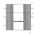
なお、上述した実施の形態1〜12では、インキ付着防止部材の一例として圧胴に装着される圧胴プレートについて説明したが、渡胴,排紙胴,反転胴などに装着されるプレートについても同様にしてそのインキ付着防止性能を判断することが可能である。図73に示した構成では渡胴4にインキ付着防止部材(プレート)24を装着している。この場合、渡胴25の周面に沿って搬送される用紙は、専用に設けられた押圧ローラ25によってプレート24の表面に押し付けられる。
In the first to twelfth embodiments described above, the impression cylinder plate attached to the impression cylinder has been described as an example of the ink adhesion preventing member, but the plate attached to the transfer cylinder, the discharge cylinder, the reversing cylinder, and the like is also described. Similarly, the ink adhesion prevention performance can be determined. In the configuration shown in FIG. 73, an ink adhesion preventing member (plate) 24 is attached to the
また、上述した実施の形態1〜12では、用紙の圧胴プレート8に押し付けられた面の撮像をオンライン(搬送中に撮像)で行うようにしたが、オフラインで行うようにしてもよい。例えば、オフラインで行う場合、圧胴プレート8に押し付けた用紙を排紙後、その用紙をオペレータが測定器112のところまで運び、そこで撮像する。
また、評価精度を向上させるために、評価時の印刷絵柄を同じにする、インキ付着状態評価箇所を同じにする、ベタ印刷部を評価する、印刷濃度を合わせるなどが考えられる。
In the first to twelfth embodiments described above, imaging of the surface pressed against the
Further, in order to improve the evaluation accuracy, it is conceivable to make the same printed pattern at the time of evaluation, make the ink adhesion state evaluation portion the same, evaluate the solid printing portion, and match the printing density.
1(1−1〜1−8)…版胴、2(2−1〜2−8)…ゴム胴、3(3−1〜3−8)…圧胴、4…渡胴、5…インキ部、6…用紙、7,7’…インキ像、8…圧胴プレート、21(21−1〜21−8)…カメラ、22…反転胴、100(100A〜100L)…インキ付着防止性能判断装置、101…CPU、102…ROM、103…RAM、104…入力装置、105…表示器、106…出力装置、107…ユニット番号設定器、108…印刷枚数設定器、109…測定位置設定器、110…ロータリーエンコーダ、111…測定位置用カウンタ、112…測定器、113…A/D変換器、114〜120…入出力インターフェイス(I/O、I/F)、M1〜M20…メモリ、200…印刷機制御装置、201…CPU、202…ROM、203…RAM、204…給紙枚数用検出器、205…給紙枚数用カウンタ、206…印刷機の原動モータ、207…原動モータ用のドライバ、208…D/A変換器、209…ロータリーエンコーダ、210…回転位相検出用カウンタ、211…給紙装置、213…胴着脱装置、215…内部クロックカウンタ、216〜221…入出力インターフェイス(I/O、I/F)、M31〜M35…メモリ。
1 (1-1 to 1-8): plate cylinder, 2 (2-1 to 2-8): rubber cylinder, 3 (3-1 to 3-8): impression cylinder, 4 ... transfer cylinder, 5 ... ink , 6 ... paper, 7, 7 '... ink image, 8 ... impression cylinder plate, 21 (21-1 to 21-8) ... camera, 22 ... reversing cylinder, 100 (100A to 100L) ... ink adhesion prevention performance judgment Device: 101 ... CPU, 102 ... ROM, 103 ... RAM, 104 ... Input device, 105 ... Display device, 106 ... Output device, 107 ... Unit number setting device, 108 ... Print number setting device, 109 ... Measurement position setting device, DESCRIPTION OF
Claims (36)
前記インキ付着防止部材がその周面に装着された回転体を回転させる工程と、
搬送される用紙を前記インキ付着防止部材の表面に押し付ける工程と、
前記用紙の前記インキ付着防止部材に押し付けられた面を撮像する工程と、
前記撮像された用紙の画像データよりその用紙に付着しているインキの付着面積を求める工程と、
前記求められた用紙のインキの付着面積より前記インキ付着防止部材のインキ付着防止性能を判断する工程と
を備えたことを特徴とするインキ付着防止性能判断方法。 In the ink adhesion prevention performance judgment method for judging the ink adhesion prevention performance of the ink adhesion prevention member having a surface that prevents the adhesion of ink,
A step of rotating the rotating body mounted on the peripheral surface of the ink adhesion preventing member;
A step of pressing the conveyed paper against the surface of the ink adhesion preventing member;
Imaging the surface of the paper pressed against the ink adhesion preventing member;
Obtaining an adhesion area of ink attached to the paper from the image data of the imaged paper;
And determining the ink adhesion prevention performance of the ink adhesion prevention member from the obtained ink adhesion area of the paper.
前記インキ付着防止部材のインキ付着防止性能を判断する工程は、
前記求められたインキの付着面積と予め定められている許容面積とを比較し、前記インキの付着面積が前記許容面積よりも大きい場合に、前記インキ付着防止部材のインキ付着防止性能が劣化したと判断する工程
を有することを特徴とするインキ付着防止性能判断方法。 In the ink adhesion prevention performance judgment method according to claim 1,
The step of judging the ink adhesion preventing performance of the ink adhesion preventing member is as follows:
The obtained ink adhesion area is compared with a predetermined allowable area, and when the ink adhesion area is larger than the allowable area, the ink adhesion preventing performance of the ink adhesion preventing member is deteriorated. A method for judging ink adhesion prevention performance, comprising the step of judging.
前記インキ付着防止部材のインキ付着防止性能を判断する工程は、
前記求められたインキの付着面積より前記用紙に付着しているインキの付着面積率を求める工程と、
前記求められたインキの付着面積率と予め定められている許容面積率とを比較し、前記インキの付着面積率が前記許容面積率よりも大きい場合に、前記インキ付着防止部材のインキ付着防止性能が劣化したと判断する工程と
を有することを特徴とするインキ付着防止性能判断方法。 In the ink adhesion prevention performance judgment method according to claim 1,
The step of judging the ink adhesion preventing performance of the ink adhesion preventing member is as follows:
A step of obtaining an adhesion area ratio of the ink adhering to the paper from the obtained ink adhesion area;
The obtained ink adhesion area ratio is compared with a predetermined allowable area ratio, and when the ink adhesion area ratio is larger than the allowable area ratio, the ink adhesion prevention performance of the ink adhesion prevention member And a step of judging that the ink has deteriorated.
前記用紙のインキの付着面積を求める工程は、
前記撮像された用紙の画像データを2値化処理する工程と、
前記2値化処理された画像データより前記用紙に付着しているインキの付着面積を求める工程と
を有することを特徴とするインキ付着防止性能判断方法。 In the ink adhesion prevention performance judgment method according to claim 1,
The step of determining the adhesion area of the ink on the paper,
Binarizing the image data of the imaged paper;
And a step of obtaining an adhesion area of ink adhering to the paper from the binarized image data.
前記用紙のインキの付着面積を求める工程は、
前記撮像された用紙の画像データを2値化処理する工程と、
前記2値化処理された画像データより連続してインキが付着した範囲の面積を求める工程と、
前記求められた連続してインキが付着した範囲の面積と予め定められている閾値とを比較し、前記連続してインキが付着した範囲の面積が前記閾値よりも大きいものだけを抽出し、その抽出した面積の合計を前記インキの付着面積とする工程と
を有することを特徴とするインキ付着防止性能判断方法。 In the ink adhesion prevention performance judgment method according to claim 1,
The step of determining the adhesion area of the ink on the paper,
Binarizing the image data of the imaged paper;
A step of obtaining an area of a range in which ink is continuously adhered from the binarized image data;
Comparing the area of the obtained range where the ink has been continuously adhered to a predetermined threshold, and extracting only those areas where the area of the area where the ink has continuously adhered is larger than the threshold, And a step of determining the total of the extracted areas as the adhesion area of the ink.
前記インキ付着防止部材がその周面に装着された回転体を回転させる工程と、
搬送される複数枚の用紙を前記インキ付着防止部材の表面に順番に押し付ける工程と、
前記複数枚の用紙の前記インキ付着防止部材に押し付けられた面を撮像する工程と、
前記撮像された用紙の画像データよりその用紙に付着しているインキの付着面積を求める工程と、
前記求められた用紙のインキの付着面積と予め定められている許容面積とを比較し、前記インキの付着面積が前記許容面積よりも小さくなった最初の用紙の前記インキ付着防止部材に押し付けられた順位を求める工程と、
前記求められた順位と予め定められている許容順位とを比較し、前記求められた順位が前記許容順位よりも後方にある場合に、前記インキ付着防止部材のインキ付着防止性能が劣化したと判断する工程と
を備えたことを特徴とするインキ付着防止性能判断方法。 In the ink adhesion prevention performance judgment method for judging the ink adhesion prevention performance of the ink adhesion prevention member having a surface that prevents the adhesion of ink,
A step of rotating the rotating body mounted on the peripheral surface of the ink adhesion preventing member;
A step of sequentially pressing a plurality of sheets of paper to be conveyed against the surface of the ink adhesion preventing member;
Imaging the surface of the plurality of sheets pressed against the ink adhesion preventing member;
Obtaining an adhesion area of ink attached to the paper from the image data of the imaged paper;
The obtained ink adhesion area of the paper was compared with a predetermined allowable area, and the ink adhesion area was pressed against the ink adhesion preventing member of the first paper that was smaller than the allowable area. A process for obtaining a ranking;
The calculated rank is compared with a predetermined allowable rank, and when the calculated rank is behind the allowable rank, it is determined that the ink adhesion preventing performance of the ink adhesion preventing member has deteriorated. An ink adhesion preventing performance judging method comprising: a step of:
前記インキ付着防止部材がその周面に装着された回転体を回転させる工程と、
搬送される複数枚の用紙を前記インキ付着防止部材の表面に順番に押し付ける工程と、
前記複数枚の用紙の前記インキ付着防止部材に押し付けられた面を撮像する工程と、
前記撮像された用紙の画像データよりその用紙に付着しているインキの付着面積を求める工程と、
前記求められたインキの付着面積より前記用紙に付着しているインキの付着面積率を求める工程と、
前記求められた用紙のインキの付着面積率と予め定められている許容面積率とを比較し、前記インキの付着面積率が前記許容面積率よりも小さくなった最初の用紙の前記インキ付着防止部材に押し付けられた順位を求める工程と、
前記求められた順位と予め定められている許容順位とを比較し、前記求められた順位が前記許容順位よりも後方にある場合に、前記インキ付着防止部材のインキ付着防止性能が劣化したと判断する工程と
を備えたことを特徴とするインキ付着防止性能判断方法。 In the ink adhesion prevention performance judgment method for judging the ink adhesion prevention performance of the ink adhesion prevention member having a surface that prevents the adhesion of ink,
A step of rotating the rotating body mounted on the peripheral surface of the ink adhesion preventing member;
A step of sequentially pressing a plurality of sheets of paper to be conveyed against the surface of the ink adhesion preventing member;
Imaging the surface of the plurality of sheets pressed against the ink adhesion preventing member;
Obtaining an adhesion area of ink attached to the paper from the image data of the imaged paper;
A step of obtaining an adhesion area ratio of the ink adhering to the paper from the obtained ink adhesion area;
The ink adhesion prevention rate of the first paper in which the ink adhesion area rate is smaller than the allowable area rate by comparing the obtained ink adhesion area rate of the paper with a predetermined allowable area rate. A process for obtaining a ranking pressed against
The calculated rank is compared with a predetermined allowable rank, and when the calculated rank is behind the allowable rank, it is determined that the ink adhesion preventing performance of the ink adhesion preventing member has deteriorated. An ink adhesion preventing performance judging method comprising: a step of:
前記インキ付着防止部材がその周面に装着された回転体を回転させる工程と、
搬送される複数枚の用紙を前記インキ付着防止部材の表面に順番に押し付ける工程と、
予め定められている順位に押し付けられた用紙の前記インキ付着防止部材に押し付けられた面を撮像する工程と、
前記撮像された用紙の画像データよりその用紙に付着しているインキの付着面積を求める工程と、
前記求められた用紙のインキの付着面積と予め定められている許容面積とを比較し、前記インキの付着面積が前記許容面積よりも大きい場合に、前記インキ付着防止部材のインキ付着防止性能が劣化したと判断する工程と
を備えたことを特徴とするインキ付着防止性能判断方法。 In the ink adhesion prevention performance judgment method for judging the ink adhesion prevention performance of the ink adhesion prevention member having a surface that prevents the adhesion of ink,
A step of rotating the rotating body mounted on the peripheral surface of the ink adhesion preventing member;
A step of sequentially pressing a plurality of sheets of paper to be conveyed against the surface of the ink adhesion preventing member;
Imaging the surface pressed against the ink adhesion preventing member of the paper pressed in a predetermined order; and
Obtaining an adhesion area of ink attached to the paper from the image data of the imaged paper;
The ink adhesion area of the obtained paper is compared with a predetermined allowable area, and when the ink adhesion area is larger than the allowable area, the ink adhesion prevention performance of the ink adhesion prevention member is deteriorated. A method for judging the ink adhesion prevention performance.
前記インキ付着防止部材がその周面に装着された回転体を回転させる工程と、
搬送される複数枚の用紙を前記インキ付着防止部材の表面に順番に押し付ける工程と、
予め定められている順位に押し付けられた用紙の前記インキ付着防止部材に押し付けられた面を撮像する工程と、
前記撮像された用紙の画像データよりその用紙に付着しているインキの付着面積を求める工程と、
前記求められたインキの付着面積より前記用紙に付着しているインキの付着面積率を求める工程と、
前記求められたインキの付着面積率と予め定められている許容面積率とを比較し、前記インキの付着面積率が前記許容面積率よりも大きい場合に、前記インキ付着防止部材のインキ付着防止性能が劣化したと判断する工程と
を備えたことを特徴とするインキ付着防止性能判断方法。 In the ink adhesion prevention performance judgment method for judging the ink adhesion prevention performance of the ink adhesion prevention member having a surface that prevents the adhesion of ink,
A step of rotating the rotating body mounted on the peripheral surface of the ink adhesion preventing member;
A step of sequentially pressing a plurality of sheets of paper to be conveyed against the surface of the ink adhesion preventing member;
Imaging the surface pressed against the ink adhesion preventing member of the paper pressed in a predetermined order; and
Obtaining an adhesion area of ink attached to the paper from the image data of the imaged paper;
A step of obtaining an adhesion area ratio of the ink adhering to the paper from the obtained ink adhesion area;
The obtained ink adhesion area ratio is compared with a predetermined allowable area ratio, and when the ink adhesion area ratio is larger than the allowable area ratio, the ink adhesion prevention performance of the ink adhesion prevention member And a method for judging that the ink has deteriorated.
前記インキ付着防止部材がその周面に装着された回転体を回転させる工程と、
搬送される用紙を前記インキ付着防止部材の表面に押し付ける工程と、
前記用紙の前記インキ付着防止部材に押し付けられた面を撮像する工程と、
前記撮像された用紙の画像データよりその用紙にインキが付着していないインキの非付着面積を求める工程と、
前記求められた用紙のインキの非付着面積より前記インキ付着防止部材のインキ付着防止性能を判断する工程と
を備えたことを特徴とするインキ付着防止性能判断方法。 In the ink adhesion prevention performance judgment method for judging the ink adhesion prevention performance of the ink adhesion prevention member having a surface that prevents the adhesion of ink,
A step of rotating the rotating body mounted on the peripheral surface of the ink adhesion preventing member;
A step of pressing the conveyed paper against the surface of the ink adhesion preventing member;
Imaging the surface of the paper pressed against the ink adhesion preventing member;
Determining the non-adhesion area of the ink that is not attached to the paper from the image data of the imaged paper;
And a step of judging the ink adhesion preventing performance of the ink adhesion preventing member from the determined ink non-adhering area of the paper.
前記インキ付着防止部材のインキ付着防止性能を判断する工程は、
前記求められたインキの非付着面積と予め定められている許容面積とを比較し、前記インキの非付着面積が前記許容面積よりも小さい場合に、前記インキ付着防止部材のインキ付着防止性能が劣化したと判断する工程
を有することを特徴とするインキ付着防止性能判断方法。 In the ink adhesion prevention performance judgment method according to claim 10,
The step of judging the ink adhesion preventing performance of the ink adhesion preventing member is as follows:
When the non-adhesion area of the obtained ink is compared with a predetermined allowable area, and the non-adhesion area of the ink is smaller than the allowable area, the ink adhesion prevention performance of the ink adhesion prevention member is deteriorated. A method for judging the performance of preventing ink adhesion.
前記インキ付着防止部材のインキ付着防止性能を判断する工程は、
前記求められたインキの非付着面積より前記用紙にインキが付着していないインキの非付着面積率を求める工程と、
前記求められたインキの非付着面積率と予め定められている許容面積率とを比較し、前記インキの非付着面積率が前記許容面積率よりも小さい場合に、前記インキ付着防止部材のインキ付着防止性能が劣化したと判断する工程と
を有することを特徴とするインキ付着防止性能判断方法。 In the ink adhesion prevention performance judgment method according to claim 10,
The step of judging the ink adhesion preventing performance of the ink adhesion preventing member is as follows:
A step of determining a non-adhesion area ratio of the ink not adhering to the paper from the determined non-adhesion area of the ink;
The non-adhesion area ratio of the obtained ink is compared with a predetermined allowable area ratio, and when the non-adhesion area ratio of the ink is smaller than the allowable area ratio, the ink adhesion of the ink adhesion prevention member And a step of judging that the prevention performance has deteriorated.
前記用紙のインキの非付着面積を求める工程は、
前記撮像された用紙の画像データを2値化処理する工程と、
前記2値化処理された画像データより前記用紙にインキが付着していないインキの非付着面積を求める工程と
を有することを特徴とするインキ付着防止性能判断方法。 In the ink adhesion prevention performance judgment method according to claim 10,
The step of determining the non-adhesion area of the ink on the paper is as follows:
Binarizing the image data of the imaged paper;
And a step of determining a non-adhesion area of the ink on which the ink is not adhered to the paper from the binarized image data.
前記用紙のインキの非付着面積を求める工程は、
前記撮像された用紙の画像データを2値化処理する工程と、
前記2値化処理された画像データより連続してインキが付着している範囲の面積を求める工程と、
前記求められた連続してインキが付着している範囲の面積と予め定められている閾値とを比較し、前記連続してインキが付着している範囲の面積が前記閾値よりも小さい面積を求め、この小面積に相当する面積を加えた前記2値化処理された画像データの非インキ付着部を示す画素の面積の合計を前記インキの非付着面積とする工程と
を有することを特徴とするインキ付着防止性能判断方法。 In the ink adhesion prevention performance judgment method according to claim 10,
The step of determining the non-adhesion area of the ink on the paper is as follows:
Binarizing the image data of the imaged paper;
A step of obtaining an area of a range in which ink is continuously adhered from the binarized image data;
The area of the range where the ink is continuously adhered is compared with a predetermined threshold value, and the area where the area of the continuous ink is adhered is smaller than the threshold value. And adding the area corresponding to the small area to the non-adhered area of the ink indicating the total area of the pixels indicating the non-ink-adhered part of the binarized image data. Ink adhesion prevention performance judgment method.
前記インキ付着防止部材がその周面に装着された回転体を回転させる工程と、
搬送される複数枚の用紙を前記インキ付着防止部材の表面に順番に押し付ける工程と、
前記複数枚の用紙の前記インキ付着防止部材に押し付けられた面を撮像する工程と、
前記撮像された用紙の画像データよりその用紙にインキが付着していないインキの非付着面積を求める工程と、
前記求められた用紙のインキの非付着面積と予め定められている許容面積とを比較し、前記インキの非付着面積が前記許容面積よりも大きくなった最初の用紙の前記インキ付着防止部材に押し付けられた順位を求める工程と、
前記求められた順位と予め定められている許容順位とを比較し、前記求められた順位が前記許容順位よりも後方にある場合に、前記インキ付着防止部材のインキ付着防止性能が劣化したと判断する工程と
を備えたことを特徴とするインキ付着防止性能判断方法。 In the ink adhesion prevention performance judgment method for judging the ink adhesion prevention performance of the ink adhesion prevention member having a surface that prevents the adhesion of ink,
A step of rotating the rotating body mounted on the peripheral surface of the ink adhesion preventing member;
A step of sequentially pressing a plurality of sheets of paper to be conveyed against the surface of the ink adhesion preventing member;
Imaging the surface of the plurality of sheets pressed against the ink adhesion preventing member;
Determining the non-adhesion area of the ink that is not attached to the paper from the image data of the imaged paper;
The determined ink non-adhesion area of the paper is compared with a predetermined allowable area, and the ink non-adhesion area is pressed against the ink adhesion preventing member of the first paper in which the ink non-adhesion area is larger than the allowable area. A process for obtaining a ranking,
The calculated rank is compared with a predetermined allowable rank, and when the calculated rank is behind the allowable rank, it is determined that the ink adhesion preventing performance of the ink adhesion preventing member has deteriorated. An ink adhesion preventing performance judging method comprising: a step of:
前記インキ付着防止部材がその周面に装着された回転体を回転させる工程と、
搬送される複数枚の用紙を前記インキ付着防止部材の表面に順番に押し付ける工程と、
前記複数枚の用紙の前記インキ付着防止部材に押し付けられた面を撮像する工程と、
前記撮像された用紙の画像データよりその用紙にインキが付着していないインキの非付着面積を求める工程と、
前記求められたインキの非付着面積より前記用紙にインキが付着していないインキの非付着面積率を求める工程と、
前記求められた用紙のインキの非付着面積率と予め定められている許容面積率とを比較し、前記インキの付着面積率が前記許容面積率よりも大きくなった最初の用紙の前記インキ付着防止部材に押し付けられた順位を求める工程と、
前記求められた順位と予め定められている許容順位とを比較し、前記求められた順位が前記許容順位よりも後方にある場合に、前記インキ付着防止部材のインキ付着防止性能が劣化したと判断する工程と
を備えたことを特徴とするインキ付着防止性能判断方法。 In the ink adhesion prevention performance judgment method for judging the ink adhesion prevention performance of the ink adhesion prevention member having a surface that prevents the adhesion of ink,
A step of rotating the rotating body mounted on the peripheral surface of the ink adhesion preventing member;
A step of sequentially pressing a plurality of sheets of paper to be conveyed against the surface of the ink adhesion preventing member;
Imaging the surface of the plurality of sheets pressed against the ink adhesion preventing member;
Determining the non-adhesion area of the ink that is not attached to the paper from the image data of the imaged paper;
A step of determining a non-adhesion area ratio of the ink not adhering to the paper from the determined non-adhesion area of the ink;
The ink non-adhesion area ratio of the obtained paper is compared with a predetermined allowable area ratio, and the ink adhesion prevention of the first paper in which the ink adhesion area ratio is larger than the allowable area ratio. A step of determining the order of pressing against the member;
The calculated rank is compared with a predetermined allowable rank, and when the calculated rank is behind the allowable rank, it is determined that the ink adhesion preventing performance of the ink adhesion preventing member has deteriorated. An ink adhesion preventing performance judging method comprising: a step of:
前記インキ付着防止部材がその周面に装着された回転体を回転させる工程と、
搬送される複数枚の用紙を前記インキ付着防止部材の表面に順番に押し付ける工程と、
予め定められている順位に押し付けられた用紙の前記インキ付着防止部材に押し付けられた面を撮像する工程と、
前記撮像された用紙の画像データよりその用紙にインキが付着していないインキの非付着面積を求める工程と、
前記求められた用紙のインキの非付着面積と予め定められている許容面積とを比較し、前記インキの非付着面積が前記許容面積よりも小さい場合に、前記インキ付着防止部材のインキ付着防止性能が劣化したと判断する工程と
を備えたことを特徴とするインキ付着防止性能判断方法。 In the ink adhesion prevention performance judgment method for judging the ink adhesion prevention performance of the ink adhesion prevention member having a surface that prevents the adhesion of ink,
A step of rotating the rotating body mounted on the peripheral surface of the ink adhesion preventing member;
A step of sequentially pressing a plurality of sheets of paper to be conveyed against the surface of the ink adhesion preventing member;
Imaging the surface pressed against the ink adhesion preventing member of the paper pressed in a predetermined order; and
Determining the non-adhesion area of the ink that is not attached to the paper from the image data of the imaged paper;
The ink non-adhesion area of the obtained paper is compared with a predetermined allowable area, and when the non-adhesion area of the ink is smaller than the allowable area, the ink adhesion prevention performance of the ink adhesion prevention member And a method for judging that the ink has deteriorated.
前記インキ付着防止部材がその周面に装着された回転体を回転させる工程と、
搬送される複数枚の用紙を前記インキ付着防止部材の表面に順番に押し付ける工程と、
予め定められている順位に押し付けられた用紙の前記インキ付着防止部材に押し付けられた面を撮像する工程と、
前記撮像された用紙の画像データよりその用紙にインキが付着していないインキの非付着面積を求める工程と、
前記求められたインキの非付着面積より前記用紙にインキが付着していないインキの非付着面積率を求める工程と、
前記求められたインキの非付着面積率と予め定められている許容面積率とを比較し、前記インキの非付着面積率が前記許容面積率よりも小さい場合に、前記インキ付着防止部材のインキ付着防止性能が劣化したと判断する工程と
を備えたことを特徴とするインキ付着防止性能判断方法。 In the ink adhesion prevention performance judgment method for judging the ink adhesion prevention performance of the ink adhesion prevention member having a surface that prevents the adhesion of ink,
A step of rotating the rotating body mounted on the peripheral surface of the ink adhesion preventing member;
A step of sequentially pressing a plurality of sheets of paper to be conveyed against the surface of the ink adhesion preventing member;
Imaging the surface pressed against the ink adhesion preventing member of the paper pressed in a predetermined order; and
Determining the non-adhesion area of the ink that is not attached to the paper from the image data of the imaged paper;
A step of determining a non-adhesion area ratio of the ink not adhering to the paper from the determined non-adhesion area of the ink;
The non-adhesion area ratio of the obtained ink is compared with a predetermined allowable area ratio, and when the non-adhesion area ratio of the ink is smaller than the allowable area ratio, the ink adhesion of the ink adhesion prevention member A method for judging the ink adhesion prevention performance, comprising the step of judging that the prevention performance has deteriorated.
前記インキ付着防止部材がその周面に装着された回転体を回転させる手段と、
搬送される用紙を前記インキ付着防止部材の表面に押し付ける手段と、
前記用紙の前記インキ付着防止部材に押し付けられた面を撮像する手段と、
前記撮像された用紙の画像データよりその用紙に付着しているインキの付着面積を求める手段と、
前記求められた用紙のインキの付着面積より前記インキ付着防止部材のインキ付着防止性能を判断する手段と
を備えたことを特徴とするインキ付着防止性能判断装置。 In the ink adhesion prevention performance judgment device for judging the ink adhesion prevention performance of the ink adhesion prevention member having the surface that prevents the adhesion of ink,
Means for rotating the rotating body on which the ink adhesion preventing member is mounted;
Means for pressing the conveyed paper against the surface of the ink adhesion preventing member;
Means for imaging the surface of the paper pressed against the ink adhesion preventing member;
Means for determining the adhesion area of the ink adhering to the paper from the image data of the imaged paper;
An ink adhesion preventing performance judging device comprising: means for judging the ink adhesion preventing performance of the ink adhesion preventing member from the obtained ink adhesion area of the paper.
前記インキ付着防止部材のインキ付着防止性能を判断する手段は、
前記求められたインキの付着面積と予め定められている許容面積とを比較し、前記インキの付着面積が前記許容面積よりも大きい場合に、前記インキ付着防止部材のインキ付着防止性能が劣化したと判断する手段
を有することを特徴とするインキ付着防止性能判断装置。 In the ink adhesion prevention performance judging device according to claim 19,
Means for judging the ink adhesion prevention performance of the ink adhesion prevention member,
The obtained ink adhesion area is compared with a predetermined allowable area, and when the ink adhesion area is larger than the allowable area, the ink adhesion preventing performance of the ink adhesion preventing member is deteriorated. An ink adhesion preventing performance judging device comprising means for judging.
前記インキ付着防止部材のインキ付着防止性能を判断する手段は、
前記求められたインキの付着面積より前記用紙に付着しているインキの付着面積率を求める手段と、
前記求められたインキの付着面積率と予め定められている許容面積率とを比較し、前記インキの付着面積率が前記許容面積率よりも大きい場合に、前記インキ付着防止部材のインキ付着防止性能が劣化したと判断する手段と
を有することを特徴とするインキ付着防止性能判断装置。 In the ink adhesion prevention performance judging device according to claim 19,
Means for judging the ink adhesion prevention performance of the ink adhesion prevention member,
Means for obtaining the adhesion area ratio of the ink adhering to the paper from the obtained ink adhesion area;
The obtained ink adhesion area ratio is compared with a predetermined allowable area ratio, and when the ink adhesion area ratio is larger than the allowable area ratio, the ink adhesion prevention performance of the ink adhesion prevention member And a means for judging that the ink has deteriorated.
前記用紙のインキの付着面積を求める手段は、
前記撮像された用紙の画像データを2値化処理する手段と、
前記2値化処理された画像データより前記用紙に付着しているインキの付着面積を求める手段と
を有することを特徴とするインキ付着防止性能判断装置。 In the ink adhesion prevention performance judging device according to claim 19,
Means for determining the ink adhesion area of the paper,
Means for binarizing the image data of the imaged paper;
Means for determining an adhesion area of ink adhering to the paper from the binarized image data.
前記用紙のインキの付着面積を求める手段は、
前記撮像された用紙の画像データを2値化処理する手段と、
前記2値化処理された画像データより連続してインキが付着した範囲の面積を求める手段と、
前記求められた連続してインキが付着した範囲の面積と予め定められている閾値とを比較し、前記連続してインキが付着した範囲の面積が前記閾値よりも大きいものだけを抽出し、その抽出した面積の合計を前記インキの付着面積とする手段と
を有することを特徴とするインキ付着防止性能判断装置。 In the ink adhesion prevention performance judging device according to claim 19,
Means for determining the ink adhesion area of the paper,
Means for binarizing the image data of the imaged paper;
Means for determining the area of the area where the ink is continuously adhered from the binarized image data;
Comparing the area of the obtained range where the ink has been continuously adhered to a predetermined threshold, and extracting only those areas where the area of the area where the ink has continuously adhered is larger than the threshold, And a means for determining the ink adhesion prevention performance.
前記インキ付着防止部材がその周面に装着された回転体を回転させる手段と、
搬送される複数枚の用紙を前記インキ付着防止部材の表面に順番に押し付ける手段と、
前記複数枚の用紙の前記インキ付着防止部材に押し付けられた面を撮像する手段と、
前記撮像された用紙の画像データよりその用紙に付着しているインキの付着面積を求める手段と、
前記求められた用紙のインキの付着面積と予め定められている許容面積とを比較し、前記インキの付着面積が前記許容面積よりも小さくなった最初の用紙の前記インキ付着防止部材に押し付けられた順位を求める手段と、
前記求められた順位と予め定められている許容順位とを比較し、前記求められた順位が前記許容順位よりも後方にある場合に、前記インキ付着防止部材のインキ付着防止性能が劣化したと判断する手段と
を備えたことを特徴とするインキ付着防止性能判断装置。 In the ink adhesion prevention performance judgment device for judging the ink adhesion prevention performance of the ink adhesion prevention member having the surface that prevents the adhesion of ink,
Means for rotating the rotating body on which the ink adhesion preventing member is mounted;
Means for sequentially pressing a plurality of sheets to be conveyed against the surface of the ink adhesion preventing member;
Means for imaging the surface of the plurality of sheets pressed against the ink adhesion preventing member;
Means for determining the adhesion area of the ink adhering to the paper from the image data of the imaged paper;
The obtained ink adhesion area of the paper was compared with a predetermined allowable area, and the ink adhesion area was pressed against the ink adhesion preventing member of the first paper that was smaller than the allowable area. A means of determining the ranking;
The calculated rank is compared with a predetermined allowable rank, and when the calculated rank is behind the allowable rank, it is determined that the ink adhesion preventing performance of the ink adhesion preventing member has deteriorated. And an ink adhesion preventing performance judging device.
前記インキ付着防止部材がその周面に装着された回転体を回転させる手段と、
搬送される複数枚の用紙を前記インキ付着防止部材の表面に順番に押し付ける手段と、
前記複数枚の用紙の前記インキ付着防止部材に押し付けられた面を撮像する手段と、
前記撮像された用紙の画像データよりその用紙に付着しているインキの付着面積を求める手段と、
前記求められたインキの付着面積より前記用紙に付着しているインキの付着面積率を求める手段と、
前記求められた用紙のインキの付着面積率と予め定められている許容面積率とを比較し、前記インキの付着面積率が前記許容面積率よりも小さくなった最初の用紙の前記インキ付着防止部材に押し付けられた順位を求める手段と、
前記求められた順位と予め定められている許容順位とを比較し、前記求められた順位が前記許容順位よりも後方にある場合に、前記インキ付着防止部材のインキ付着防止性能が劣化したと判断する手段と
を備えたことを特徴とするインキ付着防止性能判断装置。 In the ink adhesion prevention performance judgment device for judging the ink adhesion prevention performance of the ink adhesion prevention member having the surface that prevents the adhesion of ink,
Means for rotating the rotating body on which the ink adhesion preventing member is mounted;
Means for sequentially pressing a plurality of sheets to be conveyed against the surface of the ink adhesion preventing member;
Means for imaging the surface of the plurality of sheets pressed against the ink adhesion preventing member;
Means for determining the adhesion area of the ink adhering to the paper from the image data of the imaged paper;
Means for obtaining the adhesion area ratio of the ink adhering to the paper from the obtained ink adhesion area;
The ink adhesion prevention rate of the first paper in which the ink adhesion area rate is smaller than the allowable area rate by comparing the obtained ink adhesion area rate of the paper with a predetermined allowable area rate. A means for obtaining the ranking pressed against
The calculated rank is compared with a predetermined allowable rank, and when the calculated rank is behind the allowable rank, it is determined that the ink adhesion preventing performance of the ink adhesion preventing member has deteriorated. And an ink adhesion preventing performance judging device.
前記インキ付着防止部材がその周面に装着された回転体を回転させる手段と、
搬送される複数枚の用紙を前記インキ付着防止部材の表面に順番に押し付ける手段と、
予め定められている順位に押し付けられた用紙の前記インキ付着防止部材に押し付けられた面を撮像する手段と、
前記撮像された用紙の画像データよりその用紙に付着しているインキの付着面積を求める手段と、
前記求められた用紙のインキの付着面積と予め定められている許容面積とを比較し、前記インキの付着面積が前記許容面積よりも大きい場合に、前記インキ付着防止部材のインキ付着防止性能が劣化したと判断する手段と
を備えたことを特徴とするインキ付着防止性能判断装置。 In the ink adhesion prevention performance judgment device for judging the ink adhesion prevention performance of the ink adhesion prevention member having the surface that prevents the adhesion of ink,
Means for rotating the rotating body on which the ink adhesion preventing member is mounted;
Means for sequentially pressing a plurality of sheets to be conveyed against the surface of the ink adhesion preventing member;
Means for imaging the surface pressed against the ink adhesion preventing member of the paper pressed in a predetermined order;
Means for determining the adhesion area of the ink adhering to the paper from the image data of the imaged paper;
The ink adhesion area of the obtained paper is compared with a predetermined allowable area, and when the ink adhesion area is larger than the allowable area, the ink adhesion prevention performance of the ink adhesion prevention member is deteriorated. And a means for judging that the ink has been deposited.
前記インキ付着防止部材がその周面に装着された回転体を回転させる手段と、
搬送される複数枚の用紙を前記インキ付着防止部材の表面に順番に押し付ける手段と、
予め定められている順位に押し付けられた用紙の前記インキ付着防止部材に押し付けられた面を撮像する手段と、
前記撮像された用紙の画像データよりその用紙に付着しているインキの付着面積を求める手段と、
前記求められたインキの付着面積より前記用紙に付着しているインキの付着面積率を求める手段と、
前記求められたインキの付着面積率と予め定められている許容面積率とを比較し、前記インキの付着面積率が前記許容面積率よりも大きい場合に、前記インキ付着防止部材のインキ付着防止性能が劣化したと判断する手段と
を備えたことを特徴とするインキ付着防止性能判断装置。 In the ink adhesion prevention performance judgment device for judging the ink adhesion prevention performance of the ink adhesion prevention member having the surface that prevents the adhesion of ink,
Means for rotating the rotating body on which the ink adhesion preventing member is mounted;
Means for sequentially pressing a plurality of sheets to be conveyed against the surface of the ink adhesion preventing member;
Means for imaging the surface pressed against the ink adhesion preventing member of the paper pressed in a predetermined order;
Means for determining the adhesion area of the ink adhering to the paper from the image data of the imaged paper;
Means for obtaining the adhesion area ratio of the ink adhering to the paper from the obtained ink adhesion area;
The obtained ink adhesion area ratio is compared with a predetermined allowable area ratio, and when the ink adhesion area ratio is larger than the allowable area ratio, the ink adhesion prevention performance of the ink adhesion prevention member And a means for determining that the ink has deteriorated.
前記インキ付着防止部材がその周面に装着された回転体を回転させる手段と、
搬送される用紙を前記インキ付着防止部材の表面に押し付ける手段と、
前記用紙の前記インキ付着防止部材に押し付けられた面を撮像する手段と、
前記撮像された用紙の画像データよりその用紙にインキが付着していないインキの非付着面積を求める手段と、
前記求められた用紙のインキの非付着面積より前記インキ付着防止部材のインキ付着防止性能を判断する手段と
を備えたことを特徴とするインキ付着防止性能判断装置。 In the ink adhesion prevention performance judgment device for judging the ink adhesion prevention performance of the ink adhesion prevention member having the surface that prevents the adhesion of ink,
Means for rotating the rotating body on which the ink adhesion preventing member is mounted;
Means for pressing the conveyed paper against the surface of the ink adhesion preventing member;
Means for imaging the surface of the paper pressed against the ink adhesion preventing member;
Means for determining the non-adhered area of the ink not adhering to the paper from the image data of the imaged paper;
An ink adhesion preventing performance judging device comprising: a means for judging the ink adhesion preventing performance of the ink adhesion preventing member from the determined ink non-adhering area of the paper.
前記インキ付着防止部材のインキ付着防止性能を判断する手段は、
前記求められたインキの非付着面積と予め定められている許容面積とを比較し、前記インキの非付着面積が前記許容面積よりも小さい場合に、前記インキ付着防止部材のインキ付着防止性能が劣化したと判断する手段
を有することを特徴とするインキ付着防止性能判断装置。 In the ink adhesion prevention performance judging device according to claim 28,
Means for judging the ink adhesion prevention performance of the ink adhesion prevention member,
When the non-adhesion area of the obtained ink is compared with a predetermined allowable area, and the non-adhesion area of the ink is smaller than the allowable area, the ink adhesion prevention performance of the ink adhesion prevention member is deteriorated. An ink adhesion preventing performance judging device comprising means for judging that the ink has been removed.
前記インキ付着防止部材のインキ付着防止性能を判断する手段は、
前記求められたインキの非付着面積より前記用紙にインキが付着していないインキの非付着面積率を求める手段と、
前記求められたインキの非付着面積率と予め定められている許容面積率とを比較し、前記インキの非付着面積率が前記許容面積率よりも小さい場合に、前記インキ付着防止部材のインキ付着防止性能が劣化したと判断する手段と
を有することを特徴とするインキ付着防止性能判断装置。 In the ink adhesion prevention performance judging device according to claim 28,
Means for judging the ink adhesion prevention performance of the ink adhesion prevention member,
Means for determining the non-adhesion area ratio of the ink not adhering to the paper from the determined non-adhesion area of the ink;
The non-adhesion area ratio of the obtained ink is compared with a predetermined allowable area ratio, and when the non-adhesion area ratio of the ink is smaller than the allowable area ratio, the ink adhesion of the ink adhesion prevention member And a means for determining that the prevention performance has deteriorated.
前記用紙のインキの非付着面積を求める手段は、
前記撮像された用紙の画像データを2値化処理する手段と、
前記2値化処理された画像データより前記用紙にインキが付着していないインキの非付着面積を求める手段と
を有することを特徴とするインキ付着防止性能判断装置。 In the ink adhesion prevention performance judging device according to claim 28,
Means for determining the non-adhesion area of the ink of the paper,
Means for binarizing the image data of the imaged paper;
And a means for determining a non-adhesion area of the ink on which the ink is not adhered to the paper from the binarized image data.
前記用紙のインキの非付着面積を求める手段は、
前記撮像された用紙の画像データを2値化処理する手段と、
前記2値化処理された画像データより連続してインキが付着している範囲の面積を求める手段と、
前記求められた連続してインキが付着している範囲の面積と予め定められている閾値とを比較し、前記連続してインキが付着している範囲の面積が前記閾値よりも小さい面積を求め、この小面積に相当する面積を加えた前記2値化処理された画像データのインキ非付着部を示す画素の面積の合計を前記インキの非付着面積とする手段と
を有することを特徴とするインキ付着防止性能判断装置。 In the ink adhesion prevention performance judging device according to claim 28,
Means for determining the non-adhesion area of the ink of the paper,
Means for binarizing the image data of the imaged paper;
Means for obtaining an area of a range in which ink is continuously adhered from the binarized image data;
The area of the range where the ink is continuously adhered is compared with a predetermined threshold value, and the area where the area of the continuous ink is adhered is smaller than the threshold value. And means for setting the total area of pixels indicating the non-ink-adhered portion of the binarized image data to which the area corresponding to the small area is added as the non-adhered area of the ink. Ink adhesion prevention performance judgment device.
前記インキ付着防止部材がその周面に装着された回転体を回転させる手段と、
搬送される複数枚の用紙を前記インキ付着防止部材の表面に順番に押し付ける手段と、
前記複数枚の用紙の前記インキ付着防止部材に押し付けられた面を撮像する手段と、
前記撮像された用紙の画像データよりその用紙にインキが付着していないインキの非付着面積を求める手段と、
前記求められた用紙のインキの非付着面積と予め定められている許容面積とを比較し、前記インキの非付着面積が前記許容面積よりも大きくなった最初の用紙の前記インキ付着防止部材に押し付けられた順位を求める手段と、
前記求められた順位と予め定められている許容順位とを比較し、前記求められた順位が前記許容順位よりも後方にある場合に、前記インキ付着防止部材のインキ付着防止性能が劣化したと判断する手段と
を備えたことを特徴とするインキ付着防止性能判断装置。 In the ink adhesion prevention performance judgment device for judging the ink adhesion prevention performance of the ink adhesion prevention member having the surface that prevents the adhesion of ink,
Means for rotating the rotating body on which the ink adhesion preventing member is mounted;
Means for sequentially pressing a plurality of sheets to be conveyed against the surface of the ink adhesion preventing member;
Means for imaging the surface of the plurality of sheets pressed against the ink adhesion preventing member;
Means for determining the non-adhered area of the ink not adhering to the paper from the image data of the imaged paper;
The determined ink non-adhesion area of the paper is compared with a predetermined allowable area, and the ink non-adhesion area is pressed against the ink adhesion preventing member of the first paper in which the ink non-adhesion area is larger than the allowable area. A means for obtaining a given ranking;
The calculated rank is compared with a predetermined allowable rank, and when the calculated rank is behind the allowable rank, it is determined that the ink adhesion preventing performance of the ink adhesion preventing member has deteriorated. And an ink adhesion preventing performance judging device.
前記インキ付着防止部材がその周面に装着された回転体を回転させる手段と、
搬送される複数枚の用紙を前記インキ付着防止部材の表面に順番に押し付ける手段と、
前記複数枚の用紙の前記インキ付着防止部材に押し付けられた面を撮像する手段と、
前記撮像された用紙の画像データよりその用紙にインキが付着していないインキの非付着面積を求める手段と、
前記求められたインキの非付着面積より前記用紙にインキが付着していないインキの非付着面積率を求める手段と、
前記求められた用紙のインキの非付着面積率と予め定められている許容面積率とを比較し、前記インキの付着面積率が前記許容面積率よりも大きくなった最初の用紙の前記インキ付着防止部材に押し付けられた順位を求める手段と、
前記求められた順位と予め定められている許容順位とを比較し、前記求められた順位が前記許容順位よりも後方にある場合に、前記インキ付着防止部材のインキ付着防止性能が劣化したと判断する手段と
を備えたことを特徴とするインキ付着防止性能判断装置。 In the ink adhesion prevention performance judgment device for judging the ink adhesion prevention performance of the ink adhesion prevention member having the surface that prevents the adhesion of ink,
Means for rotating the rotating body on which the ink adhesion preventing member is mounted;
Means for sequentially pressing a plurality of sheets to be conveyed against the surface of the ink adhesion preventing member;
Means for imaging the surface of the plurality of sheets pressed against the ink adhesion preventing member;
Means for determining the non-adhered area of the ink not adhering to the paper from the image data of the imaged paper;
Means for determining the non-adhesion area ratio of the ink not adhering to the paper from the determined non-adhesion area of the ink;
The ink non-adhesion area ratio of the obtained paper is compared with a predetermined allowable area ratio, and the ink adhesion prevention of the first paper in which the ink adhesion area ratio is larger than the allowable area ratio. Means for determining the order of pressing against the member;
The calculated rank is compared with a predetermined allowable rank, and when the calculated rank is behind the allowable rank, it is determined that the ink adhesion preventing performance of the ink adhesion preventing member has deteriorated. And an ink adhesion preventing performance judging device.
前記インキ付着防止部材がその周面に装着された回転体を回転させる手段と、
搬送される複数枚の用紙を前記インキ付着防止部材の表面に順番に押し付ける手段と、
予め定められている順位に押し付けられた用紙の前記インキ付着防止部材に押し付けられた面を撮像する手段と、
前記撮像された用紙の画像データよりその用紙にインキが付着していないインキの非付着面積を求める手段と、
前記求められた用紙のインキの非付着面積と予め定められている許容面積とを比較し、前記インキの非付着面積が前記許容面積よりも小さい場合に、前記インキ付着防止部材のインキ付着防止性能が劣化したと判断する手段と
を備えたことを特徴とするインキ付着防止性能判断装置。 In the ink adhesion prevention performance judgment device for judging the ink adhesion prevention performance of the ink adhesion prevention member having the surface that prevents the adhesion of ink,
Means for rotating the rotating body on which the ink adhesion preventing member is mounted;
Means for sequentially pressing a plurality of sheets to be conveyed against the surface of the ink adhesion preventing member;
Means for imaging the surface pressed against the ink adhesion preventing member of the paper pressed in a predetermined order;
Means for determining the non-adhered area of the ink not adhering to the paper from the image data of the imaged paper;
The ink non-adhesion area of the obtained paper is compared with a predetermined allowable area, and when the non-adhesion area of the ink is smaller than the allowable area, the ink adhesion prevention performance of the ink adhesion prevention member And a means for determining that the ink has deteriorated.
前記インキ付着防止部材がその周面に装着された回転体を回転させる手段と、
搬送される複数枚の用紙を前記インキ付着防止部材の表面に順番に押し付ける手段と、
予め定められている順位に押し付けられた用紙の前記インキ付着防止部材に押し付けられた面を撮像する手段と、
前記撮像された用紙の画像データよりその用紙にインキが付着していないインキの非付着面積を求める手段と、
前記求められたインキの非付着面積より前記用紙にインキが付着していないインキの非付着面積率を求める手段と、
前記求められたインキの非付着面積率と予め定められている許容面積率とを比較し、前記インキの非付着面積率が前記許容面積率よりも小さい場合に、前記インキ付着防止部材のインキ付着防止性能が劣化したと判断する手段と
を備えたことを特徴とするインキ付着防止性能判断装置。
In the ink adhesion prevention performance judgment device for judging the ink adhesion prevention performance of the ink adhesion prevention member having the surface that prevents the adhesion of ink,
Means for rotating the rotating body on which the ink adhesion preventing member is mounted;
Means for sequentially pressing a plurality of sheets to be conveyed against the surface of the ink adhesion preventing member;
Means for imaging the surface pressed against the ink adhesion preventing member of the paper pressed in a predetermined order;
Means for determining the non-adhered area of the ink not adhering to the paper from the image data of the imaged paper;
Means for determining the non-adhesion area ratio of the ink not adhering to the paper from the determined non-adhesion area of the ink;
The non-adhesion area ratio of the obtained ink is compared with a predetermined allowable area ratio, and when the non-adhesion area ratio of the ink is smaller than the allowable area ratio, the ink adhesion of the ink adhesion prevention member An ink adhesion prevention performance judging device comprising: means for judging that the prevention performance has deteriorated.
Priority Applications (1)
| Application Number | Priority Date | Filing Date | Title |
|---|---|---|---|
| JP2004121673A JP2005305658A (en) | 2004-04-16 | 2004-04-16 | Anti-ink adhesion power judging method and device |
Applications Claiming Priority (1)
| Application Number | Priority Date | Filing Date | Title |
|---|---|---|---|
| JP2004121673A JP2005305658A (en) | 2004-04-16 | 2004-04-16 | Anti-ink adhesion power judging method and device |
Publications (2)
| Publication Number | Publication Date |
|---|---|
| JP2005305658A true JP2005305658A (en) | 2005-11-04 |
| JP2005305658A5 JP2005305658A5 (en) | 2007-03-08 |
Family
ID=35434979
Family Applications (1)
| Application Number | Title | Priority Date | Filing Date |
|---|---|---|---|
| JP2004121673A Ceased JP2005305658A (en) | 2004-04-16 | 2004-04-16 | Anti-ink adhesion power judging method and device |
Country Status (1)
| Country | Link |
|---|---|
| JP (1) | JP2005305658A (en) |
Citations (2)
| Publication number | Priority date | Publication date | Assignee | Title |
|---|---|---|---|---|
| JPH0482740A (en) * | 1990-05-31 | 1992-03-16 | Kanzaki Paper Mfg Co Ltd | Method and apparatus for evaluating printing irregularity |
| JP2001260561A (en) * | 2000-03-15 | 2001-09-25 | Mitsubishi Heavy Ind Ltd | Impression cylinder jacket of sheet-fed reversing press |
-
2004
- 2004-04-16 JP JP2004121673A patent/JP2005305658A/en not_active Ceased
Patent Citations (2)
| Publication number | Priority date | Publication date | Assignee | Title |
|---|---|---|---|---|
| JPH0482740A (en) * | 1990-05-31 | 1992-03-16 | Kanzaki Paper Mfg Co Ltd | Method and apparatus for evaluating printing irregularity |
| JP2001260561A (en) * | 2000-03-15 | 2001-09-25 | Mitsubishi Heavy Ind Ltd | Impression cylinder jacket of sheet-fed reversing press |
Similar Documents
| Publication | Publication Date | Title |
|---|---|---|
| US5652804A (en) | Automatic inspection of printing plates or cylinders | |
| US9143629B2 (en) | Systems and methods for streak detection in image array scanning | |
| US20130291749A1 (en) | Method and apparatus for determining and setting an optimized operating distance between at least two cylinders involved in a printing process | |
| JP2006525145A (en) | System for inspecting printed images | |
| US10623605B2 (en) | Method for image inspection of printed products using adaptive image smoothing | |
| JP2009519842A (en) | Sheet-fed printing machine | |
| JP2017047613A (en) | Inspection device, inspection method and program, and image recording device | |
| US20230202209A1 (en) | Quality Control In A Digital Printing System | |
| JP3934473B2 (en) | Patch measuring device and printing device incorporating the same | |
| JP7350637B2 (en) | High-speed image distortion correction for image inspection | |
| EP1445100B1 (en) | Printed paper inspecting method | |
| JP2003136818A (en) | Method and system for detecting image quality abnormality | |
| JPH1178183A (en) | Printed matter inspection apparatus and printer | |
| JP2005305658A (en) | Anti-ink adhesion power judging method and device | |
| US20180015745A1 (en) | Method for controlling a printing machine and stopping a transport device thereof | |
| JP2001353852A (en) | Auxiliary device for printing machine | |
| US20190377296A1 (en) | Identifying linear defects | |
| JP2003334928A (en) | Ink supply control device | |
| US11292269B2 (en) | Method for detecting and compensating for defective printing nozzles in an inkjet printing machine for reducing unusable prints | |
| US20080216685A1 (en) | Method and apparatus for measuring color density of a color bar in a printing press, and printing press equipped with color density measuring apparatus | |
| JP2006007659A (en) | Method and equipment for displaying defect of printed matter | |
| JP2020051795A (en) | Method and device for inspecting defect on printing surface | |
| JP3021986B2 (en) | Method and apparatus for evaluating printed matter | |
| JP2680588B2 (en) | Print inspection method | |
| JP2005091330A (en) | Color tone failure inspection device and method, and slight dirt inspection device and method |
Legal Events
| Date | Code | Title | Description |
|---|---|---|---|
| A521 | Written amendment |
Free format text: JAPANESE INTERMEDIATE CODE: A523 Effective date: 20070124 |
|
| A621 | Written request for application examination |
Free format text: JAPANESE INTERMEDIATE CODE: A621 Effective date: 20070124 |
|
| A977 | Report on retrieval |
Free format text: JAPANESE INTERMEDIATE CODE: A971007 Effective date: 20090430 |
|
| A131 | Notification of reasons for refusal |
Free format text: JAPANESE INTERMEDIATE CODE: A131 Effective date: 20100406 |
|
| A521 | Written amendment |
Free format text: JAPANESE INTERMEDIATE CODE: A523 Effective date: 20100604 |
|
| A01 | Written decision to grant a patent or to grant a registration (utility model) |
Free format text: JAPANESE INTERMEDIATE CODE: A01 Effective date: 20111011 |
|
| A045 | Written measure of dismissal of application |
Free format text: JAPANESE INTERMEDIATE CODE: A045 Effective date: 20120306 |