JP2005299976A - Hot air heater - Google Patents
Hot air heater Download PDFInfo
- Publication number
- JP2005299976A JP2005299976A JP2004114015A JP2004114015A JP2005299976A JP 2005299976 A JP2005299976 A JP 2005299976A JP 2004114015 A JP2004114015 A JP 2004114015A JP 2004114015 A JP2004114015 A JP 2004114015A JP 2005299976 A JP2005299976 A JP 2005299976A
- Authority
- JP
- Japan
- Prior art keywords
- hot air
- louver
- air outlet
- temperature gas
- heat
- Prior art date
- Legal status (The legal status is an assumption and is not a legal conclusion. Google has not performed a legal analysis and makes no representation as to the accuracy of the status listed.)
- Pending
Links
Images

Landscapes
- Housings, Intake/Discharge, And Installation Of Fluid Heaters (AREA)
- Direct Air Heating By Heater Or Combustion Gas (AREA)
Abstract
【課題】 温風吹き出し口に設けられたルーバーの表面温度が、暖房停止時に急速に温度低下して、誤って触れても火傷しにくい温風暖房機を提供するとともにルーバーにゴミやホコリが付着しにくいものとする。
【解決手段】 本体1内に設けられた高温ガスを発生する発熱部3と、この発熱部3により発生した高温ガスを本体1外に吹き出す温風吹き出し口8と、この温風吹き出し口8に設けられたルーバー9と、前記発熱部3の高温ガスを吹き出す温風送風機7とを備えた温風暖房機において、前記ルーバー9の表面に放熱塗料12を塗布したことを特徴とする温風暖房機。
【選択図】 図2
PROBLEM TO BE SOLVED: To provide a warm air heater that has a surface temperature of a louver provided at a hot air outlet that rapidly decreases when heating is stopped, and is not easily burned even if touched accidentally, and dust and dust adhere to the louver It is difficult to do.
SOLUTION: A heat generating portion 3 for generating a high temperature gas provided in a main body 1, a hot air outlet 8 for blowing out the high temperature gas generated by the heat generating portion 3 to the outside of the main body 1, and a hot air outlet 8 In the hot air heater provided with the provided louver 9 and the hot air blower 7 for blowing out the high-temperature gas of the heat generating part 3, the hot air heating is characterized in that a heat radiation paint 12 is applied to the surface of the louver 9. Machine.
[Selection] Figure 2
Description
本発明は、石油ファンヒータ又は電気温風機といった温風暖房機に関し、特に温風の吹き出し口に設けられたルーバーの表面に誤って触っても火傷しにくい温風暖房機に関するものである。 The present invention relates to a warm air heater such as an oil fan heater or an electric warm air heater, and more particularly to a warm air heater that is unlikely to be burned even if the surface of a louver provided at a hot air outlet is touched by mistake.
従来のこの種の温風暖房機の石油ファンヒータは、機体の内部に石油を燃焼し高温ガスを発生するためのバーナーと、このバーナーで発生した高温ガスを温風として機体外に吹き出すための温風送風機が備えられていて、温風送風機により外部の空気が機体内に取り入れられ、バーナーで発生した高温ガスを機体の前面下部に設けられた温風吹き出し口から機体外に吹き出すものである。このとき、温風吹き出し口から吹き出される温風は、温風吹き出し口に備えられたルーバーに吹き付けられ、ルーバーの働きにより方向が調節される。そして、温風の吹き出し口に備えられたルーバーは、金属板の表面に耐熱性短繊維の植毛を付着することにより熱伝導防止処理を施してあり、誤って手や指がルーバーに触れたとしても、金属板の表面に付着している植毛による熱伝導防止効果により高熱を感じることなく、火傷等の事故を防止することができる(例えば、特許文献1参照)。 The conventional oil fan heater of this type of hot air heater is a burner for burning oil inside the fuselage to generate high temperature gas, and for blowing out the hot gas generated by this burner outside the fuselage as hot air A hot air blower is provided, outside air is taken into the body by the hot air blower, and high temperature gas generated by the burner is blown out of the body from the warm air outlet provided at the lower front of the body. . At this time, the hot air blown from the hot air outlet is blown to the louver provided in the hot air outlet, and the direction is adjusted by the action of the louver. And the louver provided in the hot air outlet has been treated to prevent heat conduction by attaching flocks of heat-resistant short fibers to the surface of the metal plate, and it is assumed that a hand or finger accidentally touched the louver. However, accidents such as burns can be prevented without feeling high heat due to the heat conduction preventing effect due to the flocking attached to the surface of the metal plate (see, for example, Patent Document 1).
しかしながら、上記の従来技術において、ルーバーの表面には耐熱性短繊維の植毛を付着してあるため、ゴミやホコリがルーバーの表面の植毛に付着しやすく、外観的に芳しくないものであった。 However, in the above-described prior art, since the flocks of heat-resistant short fibers are attached to the surface of the louver, dust and dust are likely to adhere to the flocks on the surface of the louver, and the appearance is not good.
本発明は上記の問題を解決するためになされたものであり、本体内に設けられた高温ガスを発生する発熱部と、この発熱部により発生した高温ガスを本体外に吹き出す温風吹き出し口と、この温風吹き出し口に設けられたルーバーと、前記発熱部の高温ガスを吹き出す温風送風機とを備えた温風暖房機において、前記ルーバーの表面に放熱塗料を塗布したものである。 The present invention has been made in order to solve the above-described problem, and is provided with a heat generating part that generates a high-temperature gas provided in the main body, and a hot air outlet that blows out the high-temperature gas generated by the heat generating part to the outside of the main body. In the warm air heater provided with the louver provided in the warm air outlet and the warm air blower for blowing out the high temperature gas of the heat generating part, a heat radiation paint is applied to the surface of the louver.
本発明の温風暖房機は、上記のように構成したことにより、
温風の吹き出しによりルーバーの表面温度が高温になっても、ルーバーの表面に放熱塗料を塗布したため、ルーバーの表面から熱放射し易くなり、温風暖房機の運転を停止したときのルーバーの表面温度は熱放射による放熱により急速に温度が低下し、誤って手や指がルーバーに触った場合でも火傷を防止でき、安全性を保つことができる。
By configuring the hot air heater of the present invention as described above,
Even if the surface temperature of the louver becomes high due to the blowing of hot air, the surface of the louver when the operation of the hot air heater is stopped is easy because heat radiation paint is applied to the surface of the louver, making it easier to radiate heat from the surface of the louver. The temperature drops rapidly due to heat radiation by heat radiation, and even if a hand or finger touches the louver by mistake, it can prevent burns and maintain safety.
また、ルーバーの表面は平坦であるためゴミやホコリが付着しにくく外観的に優れたものとすることができる。 In addition, since the surface of the louver is flat, dust and dust are less likely to adhere, and the appearance can be improved.
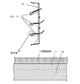
以下、本発明の一実施例を図1、図2を参照して説明する。図1は本発明の一実施例を示す温風暖房機の縦断面図、図2は同じくルーバーの縦断面図である。 An embodiment of the present invention will be described below with reference to FIGS. FIG. 1 is a longitudinal sectional view of a hot air heater showing an embodiment of the present invention, and FIG. 2 is a longitudinal sectional view of a louver.
図において、1は石油ファンヒータの本体である。2は本体1内に設けられた燃焼室で、その内部には発熱部3を構成する石油を燃焼し高温ガスを発生するバーナー4が配設されている。 In the figure, reference numeral 1 denotes a main body of an oil fan heater. Reference numeral 2 denotes a combustion chamber provided in the main body 1, and a burner 4 for combusting oil constituting the heat generating portion 3 and generating high-temperature gas is disposed therein.
5は送風経路で、燃焼室2を覆うように設けられており、その上流側は燃焼室2の背面開口部2a及び本体1の背面に開口した吸い込み口6に連なり、下流側は本体1の前面下部に設けられた後記する温風吹き出し口8に連なっている。
7は温風送風機で、吸い込み口6の内側に配設されていてバーナー4で発生する高温ガスを送風経路5を通して温風として本体1外に吹き出すものである。
A hot air blower 7 is disposed inside the
8は本体1の前面下部に設けられた温風吹き出し口で、この温風吹き出し口8は、ルーバーベース10に複数のルーバー9をカシメた構成と成っている。そして、このルーバー9により温風の方向を調節して室内に吹き出すようにしている。また、ルーバーベース10は送風経路5に押し当てる構造で、本体1内に温風が回り込まないように、燃焼室2側と本体1側を分けている。
Reference numeral 8 denotes a hot air outlet provided in the lower part of the front surface of the main body 1, and this hot air outlet 8 has a structure in which a plurality of
そして、ルーバー9とルーバーベース10は鋼材13の表面に耐熱塗料11を塗布し、さらにその上に後記する放熱塗料12が塗布されている。
And the
12は放熱塗料で、液体セラミックを主成分とした塗料で、熱を遠赤外線にして放熱するものであり、セラミックの優れた放射特性により熱放射率が約90%と高いものである。 A heat dissipating paint 12 is a paint mainly composed of a liquid ceramic, which dissipates heat by using far infrared rays, and has a high heat emissivity of about 90% due to the excellent radiation characteristics of ceramic.
本発明は以上の構成よりなり、次にその作用を説明する。 The present invention has the above configuration, and the operation thereof will be described next.
温風暖房機の運転を開始すると、発熱部3にあるバーナー4で燃焼が行われ、温風送風機7が動作して、吸い込み口6から室内の空気を送風経路5内に取り入れ、一部は燃焼室2の背面開口部2aを通して燃焼室2内の燃焼排ガスの高温ガスと混合し、他の一部は燃焼室の外側の送風経路5を通して温風吹き出し口8側に達し、そこで混合されて温風となって温風吹き出し口8のルーバー9で温風の方向が調節されて室内に放出される。
When the operation of the hot air heater is started, combustion is performed by the burner 4 in the heat generating section 3, the hot air blower 7 is operated, and the indoor air is taken into the air blowing
そして、温風吹き出し口8では、放熱塗料12を塗布したルーバー9とルーバーベース10の間を温風が流れることにより、これらに温風が当たり温度上昇して高温になっている。
At the hot air outlet 8, the hot air flows between the
温風暖房機の運転を停止すると、バーナー4の燃焼が停止し、温風送風機7の動作も停止して温風吹き出し口8からの温風の吹き出しが停止する。そうすると、温風吹き出し口8のルーバー9とルーバーベース10の表面に塗布した放熱塗料12の熱放射特性により、ルーバー9とルーバーベース10の熱が遠赤外線となって放熱するため表面温度が急速に低下するようになる。
When the operation of the hot air heater is stopped, the combustion of the burner 4 is stopped, the operation of the hot air blower 7 is also stopped, and the blowing of hot air from the hot air outlet 8 is stopped. Then, due to the heat radiation characteristics of the radiating paint 12 applied to the surfaces of the
このように、温風の吹き出しによりルーバー9及びルーバーベース10の表面温度が高温になっても、ルーバー9及びルーバーベース10の表面に放熱塗料を塗布したため、これらの表面から熱放射し易くなり、温風暖房機の運転を停止したときのルーバー9及びルーバーベース10の表面温度は熱放射による放熱により急速に温度が低下し、誤って手や指がルーバー9に触った場合でも火傷を防止でき、安全性を保つことができる。
Thus, even if the surface temperature of the
また、ルーバー9の表面は平坦であるためゴミやホコリが付着しにくく外観的に優れたものとすることができる。
Further, since the surface of the
1 本体
3 発熱部
7 温風送風機
8 温風吹き出し口
9 ルーバー
12 放熱塗料
DESCRIPTION OF SYMBOLS 1 Main body 3 Heat generating part 7 Hot air blower 8 Hot
Claims (1)
A heat generating part (3) for generating high temperature gas provided in the main body (1), a hot air outlet (8) for blowing out the high temperature gas generated by the heat generating part (3) to the outside of the main body (1), In the hot air heater comprising a louver (9) provided in the hot air outlet (8) and a hot air blower (7) for blowing out the high temperature gas of the heat generating part (3), the louver (9) A hot air heater characterized in that a heat radiation paint (12) is applied to the surface.
Priority Applications (1)
| Application Number | Priority Date | Filing Date | Title |
|---|---|---|---|
| JP2004114015A JP2005299976A (en) | 2004-04-08 | 2004-04-08 | Hot air heater |
Applications Claiming Priority (1)
| Application Number | Priority Date | Filing Date | Title |
|---|---|---|---|
| JP2004114015A JP2005299976A (en) | 2004-04-08 | 2004-04-08 | Hot air heater |
Publications (1)
| Publication Number | Publication Date |
|---|---|
| JP2005299976A true JP2005299976A (en) | 2005-10-27 |
Family
ID=35331724
Family Applications (1)
| Application Number | Title | Priority Date | Filing Date |
|---|---|---|---|
| JP2004114015A Pending JP2005299976A (en) | 2004-04-08 | 2004-04-08 | Hot air heater |
Country Status (1)
| Country | Link |
|---|---|
| JP (1) | JP2005299976A (en) |
Cited By (1)
| Publication number | Priority date | Publication date | Assignee | Title |
|---|---|---|---|---|
| DE102013005061A1 (en) | 2012-03-29 | 2013-10-02 | Fanuc Corporation | Mass cylinder-protective covering, which covers outer periphery of a mass cylinder, useful for an injection molding machine, comprises heat dissipation coating or -film applied on part of outer surface of mass cylinder-protective covering |
-
2004
- 2004-04-08 JP JP2004114015A patent/JP2005299976A/en active Pending
Cited By (1)
| Publication number | Priority date | Publication date | Assignee | Title |
|---|---|---|---|---|
| DE102013005061A1 (en) | 2012-03-29 | 2013-10-02 | Fanuc Corporation | Mass cylinder-protective covering, which covers outer periphery of a mass cylinder, useful for an injection molding machine, comprises heat dissipation coating or -film applied on part of outer surface of mass cylinder-protective covering |
Similar Documents
| Publication | Publication Date | Title |
|---|---|---|
| TWI695680B (en) | Kiln oven and its heating method | |
| TWI686137B (en) | Kiln oven | |
| TWI645784B (en) | Kiln oven | |
| CN109965719B (en) | kiln oven | |
| TWI634285B (en) | Thermal insulation structure for heating device | |
| TWI634283B (en) | Burning device | |
| TWI645783B (en) | Kiln oven | |
| CN109965721A (en) | Kiln oven | |
| JP4656866B2 (en) | Range food | |
| CN109425099A (en) | A kind of gas heater | |
| CN100455891C (en) | Gas radiant cooking appliances | |
| JP3527920B2 (en) | Hot air heater blowout structure | |
| JP2001349613A (en) | Gas hot air heater | |
| JPS6240279Y2 (en) | ||
| JP2005069526A (en) | Hot air heater | |
| KR200349600Y1 (en) | A forced convection current apparatus of infrared heater | |
| JPH03210216A (en) | gas cooker | |
| JP2001215060A (en) | Space heater | |
| AU615227B2 (en) | Heating apparatus | |
| JP2000346465A (en) | Hot air heater | |
| JP2013002697A (en) | Fan-forced heater | |
| JP2006153387A (en) | Fan forced heater | |
| JP2005077071A (en) | Gas stove | |
| JPH02275223A (en) | Gas range | |
| JP2001336750A (en) | Heating system |