JP2005299975A - Air conditioner indoor unit - Google Patents
Air conditioner indoor unit Download PDFInfo
- Publication number
- JP2005299975A JP2005299975A JP2004113982A JP2004113982A JP2005299975A JP 2005299975 A JP2005299975 A JP 2005299975A JP 2004113982 A JP2004113982 A JP 2004113982A JP 2004113982 A JP2004113982 A JP 2004113982A JP 2005299975 A JP2005299975 A JP 2005299975A
- Authority
- JP
- Japan
- Prior art keywords
- indoor unit
- air conditioner
- casing
- front panel
- panel
- Prior art date
- Legal status (The legal status is an assumption and is not a legal conclusion. Google has not performed a legal analysis and makes no representation as to the accuracy of the status listed.)
- Granted
Links
Images
Classifications
-
- F—MECHANICAL ENGINEERING; LIGHTING; HEATING; WEAPONS; BLASTING
- F24—HEATING; RANGES; VENTILATING
- F24F—AIR-CONDITIONING; AIR-HUMIDIFICATION; VENTILATION; USE OF AIR CURRENTS FOR SCREENING
- F24F1/00—Room units for air-conditioning, e.g. separate or self-contained units or units receiving primary air from a central station
- F24F1/0007—Indoor units, e.g. fan coil units
- F24F1/0011—Indoor units, e.g. fan coil units characterised by air outlets
-
- F—MECHANICAL ENGINEERING; LIGHTING; HEATING; WEAPONS; BLASTING
- F24—HEATING; RANGES; VENTILATING
- F24F—AIR-CONDITIONING; AIR-HUMIDIFICATION; VENTILATION; USE OF AIR CURRENTS FOR SCREENING
- F24F1/00—Room units for air-conditioning, e.g. separate or self-contained units or units receiving primary air from a central station
- F24F1/0007—Indoor units, e.g. fan coil units
- F24F1/0043—Indoor units, e.g. fan coil units characterised by mounting arrangements
- F24F1/0057—Indoor units, e.g. fan coil units characterised by mounting arrangements mounted in or on a wall
-
- F—MECHANICAL ENGINEERING; LIGHTING; HEATING; WEAPONS; BLASTING
- F24—HEATING; RANGES; VENTILATING
- F24F—AIR-CONDITIONING; AIR-HUMIDIFICATION; VENTILATION; USE OF AIR CURRENTS FOR SCREENING
- F24F13/00—Details common to, or for air-conditioning, air-humidification, ventilation or use of air currents for screening
- F24F13/20—Casings or covers
-
- F—MECHANICAL ENGINEERING; LIGHTING; HEATING; WEAPONS; BLASTING
- F24—HEATING; RANGES; VENTILATING
- F24F—AIR-CONDITIONING; AIR-HUMIDIFICATION; VENTILATION; USE OF AIR CURRENTS FOR SCREENING
- F24F11/00—Control or safety arrangements
- F24F11/50—Control or safety arrangements characterised by user interfaces or communication
- F24F11/56—Remote control
Landscapes
- Engineering & Computer Science (AREA)
- Chemical & Material Sciences (AREA)
- Combustion & Propulsion (AREA)
- Mechanical Engineering (AREA)
- General Engineering & Computer Science (AREA)
- Air Filters, Heat-Exchange Apparatuses, And Housings Of Air-Conditioning Units (AREA)
- Air-Conditioning Room Units, And Self-Contained Units In General (AREA)
- Air-Flow Control Members (AREA)
Abstract
【課題】 美観を向上させることができる空気調和機の室内機を提供する。
【解決手段】 空気調和機の室内機1は、室内機ケーシング2と、水平フラップ3と、正面パネル4とを備える。室内機ケーシング2は、室内へと吹き出される空気が通る吹出し口20を有する。水平フラップ3は、吹出し口20を開閉自在に設けられ、吹出し口20から吹き出される空気を案内する。正面パネル4は、閉状態において、室内機ケーシング2の少なくとも一部と、吹出し口20を閉じる水平フラップ3の少なくとも一端とを覆う。
【選択図】 図3PROBLEM TO BE SOLVED: To provide an air conditioner indoor unit capable of improving aesthetics.
An indoor unit 1 of an air conditioner includes an indoor unit casing 2, a horizontal flap 3, and a front panel 4. The indoor unit casing 2 has an outlet 20 through which air blown into the room passes. The horizontal flap 3 is provided so that the blowout opening 20 can be freely opened and closed, and guides the air blown out from the blowout opening 20. In the closed state, the front panel 4 covers at least a part of the indoor unit casing 2 and at least one end of the horizontal flap 3 that closes the outlet 20.
[Selection] Figure 3
Description
本発明は、空気調和機の室内機に関する。 The present invention relates to an indoor unit of an air conditioner.
空気調和機の室内機は、室内へと吹き出される空気が通る吹出し口を有するケーシングと、吹出し口から吹き出される空気を案内するフラップとを備えることが多い。このフラップは、吹出し口を開閉自在に設けられ、閉状態においては吹出し口を閉じるように設けられる(特許文献1参照)。
しかし、フラップが吹出し口を閉じた状態においては、フラップと吹出し口との間に境界線が生じる。従来、この境界線は、空気調和機の室内機の外観に表れており、室内の居住者等の目に触れ易い。このため、この境界線が意匠上のノイズとなり空気調和機の室内機のインテリア性を低下させるなど美観を損なう要因となっている。
本発明の課題は、美観を向上させることができる空気調和機の室内機を提供することにある。
However, when the flap closes the outlet, a boundary line is generated between the flap and the outlet. Conventionally, this boundary line appears in the appearance of an indoor unit of an air conditioner, and is easily touched by indoor residents. For this reason, this boundary line becomes noise in the design, which is a factor that impairs the aesthetics such as deteriorating the interior of the indoor unit of the air conditioner.
The subject of this invention is providing the indoor unit of the air conditioner which can improve the beauty | look.
第1発明に係る空気調和機の室内機は、ケーシングと、フラップと、正面パネルとを備える。ケーシングは、室内へと吹き出される空気が通る吹出し口を有する。フラップは、吹出し口を開閉自在に設けられ、吹出し口から吹き出される空気を案内する。正面パネルは、閉状態において、ケーシングの少なくとも一部と、吹出し口を閉じるフラップの少なくとも一端とを覆う。 An indoor unit for an air conditioner according to a first aspect of the present invention includes a casing, a flap, and a front panel. The casing has a blowout opening through which air blown into the room passes. The flap is provided so that the outlet can be opened and closed, and guides the air blown out from the outlet. In the closed state, the front panel covers at least a part of the casing and at least one end of the flap that closes the outlet.
この空気調和機の室内機では、正面パネルが、ケーシングの少なくとも一部と、吹出し口を閉じるフラップの少なくとも一端とを覆うことによって、フラップと吹出し口との境界線を隠蔽して外部から見え難くすることができる。このため、この空気調和機の室内機では、境界線によって美観が損なわれることを抑えることができ、美観を向上させることができる。 In this indoor unit of an air conditioner, the front panel covers at least a part of the casing and at least one end of the flap that closes the outlet, thereby hiding the boundary between the flap and the outlet and making it difficult to see from the outside. can do. For this reason, in this indoor unit of an air conditioner, it is possible to suppress the appearance from being damaged by the boundary line, and it is possible to improve the appearance.
第2発明に係る空気調和機の室内機は、第1発明の空気調和機の室内機であって、フラップは細長い形状を有する。そして、正面パネルは、少なくともフラップの長辺をなす一端を覆う。
この空気調和機の室内機では、正面パネルは、少なくともフラップの長辺をなす一端を覆うため、外見上、目に付き易いフラップの長辺をなす一端と吹出し口との境界線を隠蔽することができる。これにより、この空気調和機の室内機では、美観をより向上させることができる。
An indoor unit for an air conditioner according to a second aspect is the indoor unit for an air conditioner according to the first aspect, wherein the flap has an elongated shape. And a front panel covers the end which makes the long side of a flap at least.
In this indoor unit of an air conditioner, the front panel covers at least one end that forms the long side of the flap, so that the boundary line between the one end that forms the long side of the flap that is easily visible and the outlet is hidden. Can do. Thereby, in this indoor unit of an air conditioner, the beauty can be further improved.
第3発明に係る空気調和機の室内機は、第1発明または第2発明の空気調和機の室内機であって、吹出し口を閉じるフラップとケーシングとの間には、フラップを動作可能とするための隙間が設けられている。そして、正面パネルは、閉状態においてこの隙間を覆う。
フラップによって吹出し口を開閉する場合、フラップを動作可能とするため隙間が設けられることがある。すなわち、動作するフラップがケーシングと接触することを防止するために、フラップとケーシングとの間に比較的大きな隙間が設けられる。
An air conditioner indoor unit according to a third aspect of the present invention is the air conditioner indoor unit of the first or second aspect, wherein the flap is operable between the flap that closes the outlet and the casing. A gap is provided for this purpose. The front panel covers this gap in the closed state.
When the air outlet is opened and closed by the flap, a gap may be provided to enable the flap to operate. That is, a relatively large gap is provided between the flap and the casing in order to prevent the operating flap from coming into contact with the casing.
この空気調和機の室内機では、正面パネルは、閉状態においてこの隙間を覆うため、美観を損なう要因となる恐れの高い隙間を隠蔽することができる。これにより、この空気調和機の室内機では、フラップの動作を容易にすると共に美観をより向上させることができる。
第4発明に係る空気調和機の室内機は、第1発明から第3発明のいずれかの空気調和機の室内機であって、吹出し口はケーシングの下部に設けられている。そして、正面パネルは、閉状態において少なくともフラップの上端に重なる。
In the indoor unit of this air conditioner, the front panel covers the gap in the closed state, so that it is possible to hide the gap that is likely to impair the aesthetic appearance. Thereby, in this indoor unit of an air conditioner, the operation of the flap can be facilitated and the aesthetics can be further improved.
An indoor unit for an air conditioner according to a fourth aspect of the present invention is the indoor unit for an air conditioner according to any one of the first to third aspects, wherein the outlet is provided at a lower portion of the casing. The front panel overlaps at least the upper end of the flap in the closed state.
この空気調和機の室内機では、正面パネルは、閉状態において少なくともフラップの上端に重なる。このため、フラップの上端とケーシングとの間の隙間が正面パネルによって隠蔽される。これにより、この空気調和機の室内機では、フラップの上端とケーシングとの間の隙間によって美観が損なわれることを抑えることができ、美観をより向上させることができる。 In this air conditioner indoor unit, the front panel overlaps at least the upper end of the flap in the closed state. For this reason, the gap between the upper end of the flap and the casing is concealed by the front panel. Thereby, in this indoor unit of an air conditioner, it is possible to suppress the appearance from being damaged by the gap between the upper end of the flap and the casing, and it is possible to further improve the appearance.
第5発明に係る空気調和機の室内機は、第1発明から第4発明のいずれかの空気調和機の室内機であって、正面パネルは、閉状態において、フラップの少なくとも一端と、ケーシング内へ取り込まれる空気が通る吸込み口とを覆う。
この空気調和機の室内機では、正面パネルは、閉状態において、フラップの一端だけではなく吸込み口も覆う。このため、閉状態において、吸込み口も隠蔽することができる。これにより、この空気調和機の室内機では、美観をより向上させることができる。
An indoor unit of an air conditioner according to a fifth aspect of the present invention is the indoor unit of the air conditioner of any one of the first to fourth aspects, wherein the front panel is in a closed state and at least one end of the flap and the casing Covers the air inlet through which the air taken in.
In this air conditioner indoor unit, the front panel covers not only one end of the flap but also the suction port in the closed state. For this reason, in a closed state, a suction inlet can also be concealed. Thereby, in this indoor unit of an air conditioner, the beauty can be further improved.
第6発明に係る空気調和機の室内機は、第5発明の空気調和機の室内機であって、正面パネルは、フラップの少なくとも一端を覆う第1パネル部と、吸込み口を覆う第2パネル部とを有する。また、第1パネル部と第2パネル部とは一体化されている。
この空気調和機の室内機では、第1パネル部と第2パネル部とが一体化されている正面パネルによって、フラップの少なくとも一端および吸込み口を覆うことができる。従って、第1パネル部と第2パネル部とが別体とされる場合と比べて、部品構成を簡素化することができる。
An indoor unit of an air conditioner according to a sixth aspect of the invention is the indoor unit of the air conditioner of the fifth aspect, wherein the front panel includes a first panel portion that covers at least one end of the flap, and a second panel that covers the suction port. Part. Moreover, the 1st panel part and the 2nd panel part are integrated.
In this indoor unit of an air conditioner, at least one end of the flap and the suction port can be covered with the front panel in which the first panel portion and the second panel portion are integrated. Therefore, compared with the case where the 1st panel part and the 2nd panel part are made into a different body, parts composition can be simplified.
第7発明に係る空気調和機の室内機は、第6発明の空気調和機の室内機であって、ケーシングは、第1ケーシング面と第2ケーシング面とを有する。第1ケーシング面には、吹出し口が設けられる。第2ケーシング面には、吸込み口が設けられ、第2ケーシング面は、第1ケーシング面に対して所定角度をなす。そして、第1パネル部と第2パネル部とは、閉状態において第1ケーシング面および第2ケーシング面に沿うように所定角度で一体化されている。 An indoor unit for an air conditioner according to a seventh aspect is the indoor unit for an air conditioner according to the sixth aspect, wherein the casing has a first casing surface and a second casing surface. A blowout port is provided on the first casing surface. The second casing surface is provided with a suction port, and the second casing surface forms a predetermined angle with respect to the first casing surface. And the 1st panel part and the 2nd panel part are integrated by the predetermined angle so that the 1st casing surface and the 2nd casing surface may be met in a closed state.
この空気調和機の室内機では、第1パネル部と第2パネル部とは、閉状態において第1ケーシング面および第2ケーシング面に沿うように所定角度で一体化されている。このため、正面パネルは、第1ケーシング面と第2ケーシング面とに沿った形状となっており、フラップの少なくとも一端および吸込み口を共に覆うことができる。
第8発明に係る空気調和機の室内機は、第7発明の空気調和機の室内機であって、正面パネルは、第1パネル部が第1ケーシング面に沿って移動すると共に第2パネル部が第2ケーシング面から離れるように移動することによって、吹出し口および吸込み口を開く。
In the indoor unit of this air conditioner, the first panel portion and the second panel portion are integrated at a predetermined angle along the first casing surface and the second casing surface in the closed state. For this reason, the front panel has a shape along the first casing surface and the second casing surface, and can cover both at least one end of the flap and the suction port.
An indoor unit of an air conditioner according to an eighth aspect of the present invention is the indoor unit of the air conditioner of the seventh aspect, wherein the front panel moves along the first casing surface and the second panel unit as the first panel unit moves. Is moved away from the second casing surface to open the outlet and the inlet.
この空気調和機の室内機では、正面パネルは、第1パネル部が第1ケーシング面に沿って移動すると共に第2パネル部が第2ケーシング面から離れるように移動することによって、吹出し口および吸込み口を開く。第1パネル部および第2パネル部が別体とされている場合には、吹出し口および吸込み口の開閉動作が複雑なものとなり易いが、この空気調和機の室内機では、一体化された正面パネルが上記のように移動することによって、吹出し口および吸込み口を簡易に開くことができる。これにより、この空気調和機の室内機では、正面パネルの簡易な動作によって、吹出し口及び吸込み口を開くことができる。 In the indoor unit of this air conditioner, the front panel has a blowout port and a suction port by moving the first panel portion along the first casing surface and moving the second panel portion away from the second casing surface. Open mouth. When the first panel part and the second panel part are separate bodies, the opening and closing operations of the air outlet and the air inlet are likely to be complicated, but in this indoor unit of the air conditioner, an integrated front By moving the panel as described above, the blowout port and the suction port can be easily opened. Thereby, in this indoor unit of an air conditioner, the outlet and the inlet can be opened by a simple operation of the front panel.
第9発明に係る空気調和機の室内機は、第8発明の空気調和機の室内機であって、第1パネル部は、正面パネルが吹出し口および吸込み口を開いた開状態において第2パネル部と第2ケーシング面との間を塞ぐ。
この空気調和機の室内機では、第1パネル部が、開状態において第2パネル部と第2ケーシングとの間を塞ぐことができる。これにより、この空気調和機の室内機では、吹出し口から吹き出された空気が第2パネル部と第2ケーシングとの間を通って吸込み口から吸い込まれることを抑えることができる。
An indoor unit of an air conditioner according to a ninth aspect of the present invention is the indoor unit of the air conditioner of the eighth aspect, wherein the first panel portion is the second panel in the open state in which the front panel opens the air outlet and the air inlet. The space between the part and the second casing surface is closed.
In the indoor unit of this air conditioner, the first panel portion can block between the second panel portion and the second casing in the open state. Thereby, in this indoor unit of the air conditioner, it is possible to suppress the air blown from the blowout port from being sucked from the suction port through between the second panel portion and the second casing.
第10発明に係る空気調和機の室内機は、第1発明から第9発明のいずれかの空気調和機の室内機であって、吹出し口は、ケーシングの幅方向に細長い形状を有する。そして、正面パネルは、幅方向に吹出し口よりも長い形状を有する。
この空気調和機の室内機では、正面パネルは、幅方向に吹出し口よりも長い形状を有する。このため、正面パネルによって、フラップと吹出し口との境界線をより広範囲に亘って隠蔽することができる。これにより、この空気調和機の室内機では、美観をより向上させることができる。
An indoor unit of an air conditioner according to a tenth aspect of the present invention is the indoor unit of the air conditioner according to any one of the first to ninth aspects of the invention, and the outlet has an elongated shape in the width direction of the casing. And a front panel has a shape longer than a blower outlet in the width direction.
In the indoor unit of this air conditioner, the front panel has a shape longer than the outlet in the width direction. For this reason, the front panel can conceal the boundary line between the flap and the air outlet over a wider range. Thereby, in this indoor unit of an air conditioner, the beauty can be further improved.
第11発明に係る空気調和機の室内機は、第10発明の空気調和機の室内機であって、正面パネルは、ケーシングの幅と略同じ幅を有する。
この空気調和機の室内機では、正面パネルは、ケーシングの幅と略同じ幅を有する。このため、正面パネルによって、ケーシングの表面に現れる美観を妨げる恐れのある要素をより広範囲に亘って隠蔽することができる。これにより、この空気調和機の室内機では、美観をより向上させることができる。
An indoor unit of an air conditioner according to an eleventh aspect of the invention is the indoor unit of the air conditioner of the tenth aspect, wherein the front panel has a width that is substantially the same as the width of the casing.
In this air conditioner indoor unit, the front panel has substantially the same width as the casing. For this reason, the front panel can conceal an element that may interfere with the aesthetic appearance that appears on the surface of the casing over a wider range. Thereby, in this indoor unit of an air conditioner, the beauty can be further improved.
第12発明に係る空気調和機の室内機は、第1発明から第11発明のいずれかの空気調和機の室内機であって、正面パネルは正面視において上下方向に伸びる継ぎ目を有さない。
この空気調和機の室内機では、正面パネルは正面視において上下方向に伸びる継ぎ目を有さない。従って、この空気調和機の室内機では、外観上美観を妨げる恐れのある要素がより少なくなっている。これにより、この空気調和機の室内機では、美観をより向上させることができる。
An indoor unit of an air conditioner according to a twelfth aspect of the present invention is the indoor unit of any one of the first to eleventh aspects of the present invention, wherein the front panel does not have a seam extending in the vertical direction when viewed from the front.
In this air conditioner indoor unit, the front panel does not have a seam extending in the vertical direction when viewed from the front. Therefore, in this indoor unit of an air conditioner, there are fewer elements that may hinder aesthetic appearance. Thereby, in this indoor unit of an air conditioner, the beauty can be further improved.
第1発明に係る空気調和機の室内機では、正面パネルが、フラップと吹出し口との境界線を隠蔽して外部から見え難くすることができる。このため、この空気調和機の室内機では、境界線によって美観が損なわれることを抑えることができ、美観を向上させることができる。
第2発明に係る空気調和機の室内機では、正面パネルは、外見上、目に付き易いフラップの長辺をなす一端と吹出し口との境界線を隠蔽することができる。これにより、この空気調和機の室内機では、美観をより向上させることができる。
In the indoor unit for an air conditioner according to the first aspect of the present invention, the front panel can conceal the boundary line between the flap and the outlet and make it difficult to see from the outside. For this reason, in this indoor unit of an air conditioner, it is possible to suppress the appearance from being damaged by the boundary line, and it is possible to improve the appearance.
In the indoor unit of an air conditioner according to the second aspect of the invention, the front panel can conceal the boundary line between the one end forming the long side of the flap that is easily visible and the outlet. Thereby, in this indoor unit of an air conditioner, the beauty can be further improved.
第3発明に係る空気調和機の室内機では、正面パネルは、美観を損なう要因となる恐れの高い隙間を隠蔽することができる。これにより、この空気調和機の室内機では、フラップの動作を容易にすると共に美観をより向上させることができる。
第4発明に係る空気調和機の室内機では、フラップの上端とケーシングとの間の隙間が正面パネルによって隠蔽される。これにより、この空気調和機の室内機では、フラップの上端とケーシングとの間の隙間によって美観が損なわれることを抑えることができ、美観をより向上させることができる。
In the indoor unit of an air conditioner according to the third aspect of the invention, the front panel can conceal a gap that is likely to cause a loss of aesthetics. Thereby, in this indoor unit of an air conditioner, the operation of the flap can be facilitated and the aesthetics can be further improved.
In the indoor unit for an air conditioner according to the fourth aspect of the present invention, the gap between the upper end of the flap and the casing is concealed by the front panel. Thereby, in this indoor unit of an air conditioner, it is possible to suppress the appearance from being damaged by the gap between the upper end of the flap and the casing, and it is possible to further improve the appearance.
第5発明に係る空気調和機の室内機では、正面パネルは、閉状態において、吸込み口も隠蔽することができる。これにより、この空気調和機の室内機では、美観をより向上させることができる。
第6発明に係る空気調和機の室内機では、第1パネル部と第2パネル部とが一体化されている正面パネルによって、フラップの少なくとも一端および吸込み口を覆うことができる。従って、第1パネル部と第2パネル部とが別体とされる場合と比べて、部品構成を簡素化することができる。
In the indoor unit for an air conditioner according to the fifth aspect of the present invention, the front panel can also conceal the suction port in the closed state. Thereby, in this indoor unit of an air conditioner, the beauty can be further improved.
In the indoor unit of an air conditioner according to the sixth aspect of the present invention, at least one end of the flap and the suction port can be covered with the front panel in which the first panel portion and the second panel portion are integrated. Therefore, compared with the case where the 1st panel part and the 2nd panel part are made into a different body, parts composition can be simplified.
第7発明に係る空気調和機の室内機では、正面パネルは、第1ケーシング面と第2ケーシング面とに沿った形状となっており、フラップの少なくとも一端および吸込み口を共に覆うことができる。
第8発明に係る空気調和機の室内機では、一体化された正面パネルが移動することによって、吹出し口および吸込み口を簡易に開くことができる。これにより、この空気調和機の室内機では、正面パネルの簡易な動作によって、吹出し口及び吸込み口を開くことができる。
In the indoor unit of an air conditioner according to the seventh aspect of the present invention, the front panel has a shape along the first casing surface and the second casing surface, and can cover at least one end of the flap and the suction port.
In the indoor unit for an air conditioner according to the eighth aspect of the present invention, the blowout port and the suction port can be easily opened by moving the integrated front panel. Thereby, in this indoor unit of an air conditioner, the outlet and the inlet can be opened by a simple operation of the front panel.
第9発明に係る空気調和機の室内機では、吹出し口から吹き出された空気が第2パネル部と第2ケーシングとの間を通って吸込み口から吸い込まれることを抑えることができる。
第10発明に係る空気調和機の室内機では、正面パネルによって、フラップと吹出し口との境界線をより広範囲に亘って隠蔽することができる。これにより、この空気調和機の室内機では、美観をより向上させることができる。
In the indoor unit for an air conditioner according to the ninth aspect of the present invention, it is possible to suppress the air blown from the blowout port from being sucked from the suction port through between the second panel portion and the second casing.
In the indoor unit for an air conditioner according to the tenth aspect, the boundary line between the flap and the outlet can be concealed over a wider range by the front panel. Thereby, in this indoor unit of an air conditioner, the beauty can be further improved.
第11発明に係る空気調和機の室内機では、正面パネルによって、ケーシングの表面に現れる美観を妨げる恐れのある要素をより広範囲に亘って隠蔽することができる。これにより、この空気調和機の室内機では、美観をより向上させることができる。
第12発明に係る空気調和機の室内機では、外観上美観を妨げる恐れのある要素がより少なくなっている。これにより、この空気調和機の室内機では、美観をより向上させることができる。
In the indoor unit for an air conditioner according to the eleventh aspect, the front panel can conceal an element that may interfere with the aesthetic appearance that appears on the surface of the casing over a wider range. Thereby, in this indoor unit of an air conditioner, the beauty can be further improved.
In the indoor unit of an air conditioner according to the twelfth aspect, there are fewer elements that may hinder aesthetic appearance. Thereby, in this indoor unit of an air conditioner, the beauty can be further improved.
<構成>
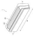
本発明の一実施形態にかかる空気調和機の室内機1を図1および図2に示す。図1は空気調和機の室内機1の正面図であり、図2は空気調和機の室内機1の側面図である。この空気調和機の室内機1は、室内の壁面に取り付けられる壁掛け型室内機であり、室内の冷暖房等の空気調和を行う。この空気調和機の室内機1は、室内機ケーシング2(ケーシング)と、水平フラップ3(フラップ)と、正面パネル4とを備えている。
<Configuration>
1 and 2 show an
[室内機ケーシング]
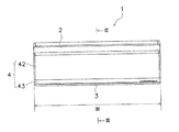
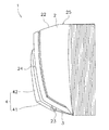
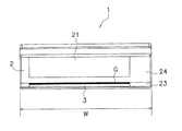
室内機ケーシング2は、図1に示すように、正面視において水平方向に長い長方形形状を有しており、図示しない室内熱交換器、室内ファン、制御部品などを収容する。室内機ケーシング2の正面には、正面パネル4が取り付けられている。正面パネル4については、後に詳細に説明する。室内機ケーシング2には、図3に示すように、吹出し口20、第1吸込み口21(吸込み口)および第2吸込み口22が設けられている。なお、図3は、室内機1の側面断面図である。
[Indoor unit casing]
As shown in FIG. 1, the
吹出し口20は、室内へと吹き出される空気が通る開口であり、第1ケーシング面23に設けられている。第1ケーシング面23は、図2に示すように、室内機ケーシング2の底面の前側部分を構成しており、吹出し口20は、室内機ケーシング2の下部に設けられている。第1ケーシング面23は、前端が上方に位置するように傾斜している。吹出し口20は、室内機ケーシング2の幅W方向(室内機ケーシング2の長手方向、図1参照)に細長い形状を有しており、水平フラップ3が設けられる。
The
図3に示す第1吸込み口21は、室内機ケーシング2内へと取り込まれる空気が通る開口であり、第2ケーシング面24に設けられている。第2ケーシング面24は、図2に示すように、室内機ケーシング2の正面を構成しており、第1吸込み口21は、室内機ケーシング2の正面に設けられる。第2ケーシング面24は、上下方向に伸びる略平坦な形状となっているが、上端が前方に位置するように僅かに傾斜している。第2ケーシング面24の下端は、第1ケーシング面23の上端と連続しており、第2ケーシング面24は、第1ケーシング面23に対して所定角度をなしている。すなわち、第1ケーシング面23と第2ケーシング面24とは、屈曲した形状となっており、90度以上180度未満の比較的緩やかな角度をなしている。
The
第2吸込み口22は、室内機ケーシング2内へと取り込まれる空気が通る開口であり、図4に示すように、室内機ケーシング2の天面25に設けられている。第2吸込み口22は、室内機ケーシング2の幅W方向に伸びる複数のスリットによって構成されている。
[水平フラップ]
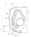
水平フラップ3は、吹出し口20を開閉自在に設けられ、吹出し口20から吹き出される空気を案内する。水平フラップ3は、室内機ケーシング2の幅W方向に細長い略長方形形状を有し、室内機ケーシング2の幅W方向に平行な軸を中心に回動自在に吹出し口20に設けられる。水平フラップ3は、吹出し口20よりも僅かに小さい形状を有するが、図5に示すように、吹出し口20を閉じる水平フラップ3の上端と室内機ケーシング2との間には、隙間Gが設けられている。この隙間Gが設けられることによって、水平フラップ3は、吹出し口20において制限少なく回動可能となっている。なお、図5は、正面パネル4を取り外した状態における室内機1の正面図である。
The
[Horizontal flap]
The
[正面パネル]
正面パネル4は、第1吸込み口21を開閉すると共に、閉状態において、室内機ケーシング2の少なくとも一部と、吹出し口20を閉じる水平フラップ3の少なくとも一端とを覆う。具体的には、正面パネル4は、図2および図3に示すように、水平フラップ3の長辺をなす上端近傍、第1ケーシング面23および第2ケーシング面24の途中までの部分に外側から重なる。従って、正面パネル4は、閉状態において、上述した水平フラップ3の上端と吹出し口20との間の隙間Gを覆う。正面パネル4は、室内機ケーシング2の第1ケーシング面23および第2ケーシング面24の屈曲に沿うように屈曲した形状を有している。正面パネル4は、室内機ケーシング2の幅W方向に吹出し口20よりも長い形状を有しており、室内機ケーシング2の幅Wと略同じ幅Wを有する。また、正面パネル4は、図1に示すように、正面視において上下方向に伸びる継ぎ目を有さない。正面パネル4は、第1パネル部41と第2パネル部42とを有する。
[Front panel]
The
第1パネル部41は、正面パネル4の閉状態において、水平フラップ3の上端を覆う部分である。第1パネル部41は、正面パネル4の下部を構成している。
第2パネル部42は、正面パネル4の閉状態において、第1吸込み口21を覆う部分である。第2パネル部42は、正面パネル4の上部を構成している。
第1パネル部41の上端と第2パネル部42の下端とは連続しており、第1パネル部41と第2パネル部42とは、正面パネル4の閉状態において、第1ケーシング面23および第2ケーシング面24に沿うように所定角度で一体化されている。
The
The
The upper end of the
なお、正面パネル4は、両側端をそれぞれ支持板43,44によって支持されている(図7参照)。2つの支持板43,44は、室内機ケーシング2の両側端に設けられており、それぞれ前後に移動可能に設けられている。これらの支持板43,44が移動することによって正面パネル4が移動する。
<開閉動作>
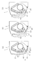
次に、正面パネル4の開閉動作について図6に基づいて詳細に説明する。
The
<Opening and closing operation>
Next, the opening / closing operation | movement of the
空気調和機の室内機1は、運転停止時に、水平フラップ3によって吹出し口20をと実と共に正面パネルを閉状態とする。正面パネル4は、閉状態において、図6(a)に示すように、第1吸込み口21を覆うと共に水平フラップ3の上端を覆う。この閉状態において、第1パネル部41は、水平フラップ3の上端、水平フラップ3の上端と吹出し口20との間の隙間Gおよび第1ケーシング面23の吹出し口20近傍を覆う。また、第2パネル部42は、第2ケーシング面24を覆う。正面パネル4は、屈曲した形状を有しており、閉状態では、第1ケーシング面23および第2ケーシング面24に沿って、第1ケーシング面23および第2ケーシング面24に近接した状態となる。これにより、室内機1の運転停止時に、水平フラップ3の上端から第1吸込み口21までの部分が外部から隠蔽される。
When the
次に、空気調和機の室内機1は、運転開始時に、正面パネルを開状態とする。正面パネル4は、図6(b)に示すように、斜め上前方へと移動することにより開状態となる(矢印A1参照)。このとき、第1パネル部41が第1ケーシング面23に沿って斜め上前方へと移動すると共に第2パネル部42が第2ケーシング面24から離れるように斜め上前方へと移動することによって、正面パネル4は吹出し口20および第1吸込み口21を開く。このとき、第1パネル部41は、下端が吹出し口20の上端を越える位置まで移動して第1パネル部41が吹出し口20からの吹き出しを妨げないようにされると共に、第1パネル部41が第2パネル部42と第2ケーシング面24との間の下部を塞ぐ。そして、図6(c)に示すように、吹出し口20を閉じていた水平フラップ3が回動することによって、吹出し口20が開かれる。また、この状態においては、図7に示すように、第2パネル部42と第2ケーシング面24との間の上部は開かれており、第1吸込み口21から取り込まれる空気が通ることができる。なお、開状態においては、第2パネル部42と第2ケーシング面24との間の両側部は支持板43,44によって塞がれており、この支持板43,44が目隠し板となって外部から第1吸込み口21を通して室内機ケーシング2の内部が見えないようにされている。
Next, the
室内機1の運転停止時には、水平フラップ3が回動して吹出し口20を閉じた後、正面パネル4が上記とは逆に移動して、水平フラップ3の上端から第1吸込み口21までの部分が再び外部から隠蔽される。
<特徴>
(1)
この空気調和機の室内機1では、運転停止時において、水平フラップ3の上端から第1吸込み口21までの部分が正面パネル4によって隠蔽される。このため、水平フラップ3を回動可能とするための比較的大きな隙間Gが外部から見え難くなる。これにより、この空気調和機の室内機1では、インテリア性が向上するなど美観が向上している。
When the operation of the
<Features>
(1)
In the
また、上記のような正面パネル4が設けられていない場合にこのような隙間Gを正面に露出させないためには、隙間Gを小さくすることが必要となるが、この場合、水平フラップ3の回転方向に制限ができる。しかし、この空気調和機の室内機1では、そのような水平フラップ3の回転方向の制限が緩和されている。
(2)
この空気調和機の室内機1では、上述したように、水平フラップ3を回動可能とするための比較的大きな隙間Gが正面パネル4によって覆われる。このため、室内機1の運転停止における室内機ケーシング2内の密閉度が向上している。
Further, when the
(2)
In the
また、室内機1の運転停止時において、隙間Gから虫などの小動物や埃などの室内機ケーシング2の内部への侵入を防止することができる。
(3)
この空気調和機の室内機1では、隙間Gを隠蔽するための第1パネル部41と第1吸込み口21を覆うための第2パネル部42とが一体化された正面パネル4によって、第1吸込み口21と水平フラップ3の上端との隠蔽が行われる。このため、第1パネル部41と第2パネル部42とが別々に動作する場合と比べて、簡素な動作によって吹出し口20および第1吸込み口21の開閉を行うことができる。
Further, when the operation of the
(3)
In the
(4)
この空気調和機の室内機1では、正面パネル4が屈曲した形状となっている。このため、正面パネル4が斜め上前方へと移動することによって、第1パネル部41が、第2パネル部42と第2ケーシング面24との間の下端を塞ぐ状態となる。このため、開状態において、吹出し口20から吹き出された空気が、第2パネル部42と第2ケーシング面24との間の下部を通って再び第1吸込み口21から吸い込まれるショートサーキットの発生を防止することができる。また、ショートサーキットが防止されるため、正面パネル4を比較的大きく移動させることができ、第2パネル部42と第2ケーシング面24との間の上部に設けられる開口の面積を大きく確保することができる。
(4)
In the
<他の実施形態>
上記の実施形態では、円滑な開閉動作のために正面パネル4の下端の長さが短くなっており、水平フラップ3の下端近傍は正面パネル4によって覆われていない。しかし、美観向上の観点からは、正面パネル4が水平フラップ3の全体を覆うものであってもよい。
<Other embodiments>
In the above embodiment, the length of the lower end of the
本発明は、美観を向上させることができる効果を有し、空気調和機の室内機として有用である。 The present invention has an effect of improving aesthetics and is useful as an indoor unit of an air conditioner.
1 空気調和機の室内機
2 室内機ケーシング(ケーシング)
3 水平フラップ(フラップ)
4 正面パネル
20 吹出し口
21 第1吸込み口(吸込み口)
23 第1ケーシング面
24 第2ケーシング面
41 第1パネル部
42 第2パネル部
G 隙間
W ケーシングの幅
1 Air conditioner
3 Horizontal flaps (flaps)
4
23
本発明は、空気調和機の室内機に関する。 The present invention relates to an indoor unit of an air conditioner.
空気調和機の室内機は、室内へと吹き出される空気が通る吹出し口を有するケーシングと、吹出し口から吹き出される空気を案内するフラップとを備えることが多い。このフラップは、吹出し口を開閉自在に設けられ、閉状態においては吹出し口を閉じるように設けられる(特許文献1参照)。
しかし、フラップが吹出し口を閉じた状態においては、フラップと吹出し口との間に境界線が生じる。従来、この境界線は、空気調和機の室内機の外観に表れており、室内の居住者等の目に触れ易い。このため、この境界線が意匠上のノイズとなり空気調和機の室内機のインテリア性を低下させるなど美観を損なう要因となっている。
本発明の課題は、美観を向上させることができる空気調和機の室内機を提供することにある。
However, when the flap closes the outlet, a boundary line is generated between the flap and the outlet. Conventionally, this boundary line appears in the appearance of an indoor unit of an air conditioner, and is easily touched by indoor residents. For this reason, this boundary line becomes noise in the design, which is a factor that impairs the aesthetics such as deteriorating the interior of the indoor unit of the air conditioner.
The subject of this invention is providing the indoor unit of the air conditioner which can improve the beauty | look.
第1発明に係る空気調和機の室内機は、ケーシングと、フラップと、正面パネルとを備える。ケーシングは、室内へと吹き出される空気が通る吹出し口を有する。フラップは、吹出し口を開閉自在に設けられ、吹出し口から吹き出される空気を案内する。正面パネルは、閉状態において、ケーシングの少なくとも一部と、吹出し口を閉じるフラップの少なくとも一端とを覆う。 An indoor unit for an air conditioner according to a first aspect of the present invention includes a casing, a flap, and a front panel. The casing has a blowout opening through which air blown into the room passes. The flap is provided so that the outlet can be opened and closed, and guides the air blown out from the outlet. In the closed state, the front panel covers at least a part of the casing and at least one end of the flap that closes the outlet.
この空気調和機の室内機では、正面パネルが、ケーシングの少なくとも一部と、吹出し口を閉じるフラップの少なくとも一端とを覆うことによって、フラップと吹出し口との境界線を隠蔽して外部から見え難くすることができる。このため、この空気調和機の室内機では、境界線によって美観が損なわれることを抑えることができ、美観を向上させることができる。 In this indoor unit of an air conditioner, the front panel covers at least a part of the casing and at least one end of the flap that closes the outlet, thereby hiding the boundary between the flap and the outlet and making it difficult to see from the outside. can do. For this reason, in this indoor unit of an air conditioner, it is possible to suppress the appearance from being damaged by the boundary line, and it is possible to improve the appearance.
第2発明に係る空気調和機の室内機は、第1発明の空気調和機の室内機であって、フラップは細長い形状を有する。そして、正面パネルは、少なくともフラップの長辺をなす一端を覆う。
この空気調和機の室内機では、正面パネルは、少なくともフラップの長辺をなす一端を覆うため、外見上、目に付き易いフラップの長辺をなす一端と吹出し口との境界線を隠蔽することができる。これにより、この空気調和機の室内機では、美観をより向上させることができる。
An indoor unit for an air conditioner according to a second aspect is the indoor unit for an air conditioner according to the first aspect, wherein the flap has an elongated shape. And a front panel covers the end which makes the long side of a flap at least.
In this indoor unit of an air conditioner, the front panel covers at least one end that forms the long side of the flap, so that the boundary line between the one end that forms the long side of the flap that is easily visible and the outlet is hidden. Can do. Thereby, in this indoor unit of an air conditioner, the beauty can be further improved.
第3発明に係る空気調和機の室内機は、第1発明または第2発明の空気調和機の室内機であって、吹出し口を閉じるフラップとケーシングとの間には隙間が設けられている。そして、正面パネルは、閉状態においてこの隙間を覆う。
この空気調和機の室内機では、正面パネルは、閉状態において隙間を覆うため、美観を損なう要因となる恐れの高い隙間を隠蔽することができる。これにより、この空気調和機の室内機では、フラップの動作を容易にすると共に美観をより向上させることができる。
An air conditioner indoor unit according to a third aspect of the present invention is the air conditioner indoor unit of the first aspect or the second aspect, wherein a gap is provided between the flap that closes the outlet and the casing. The front panel covers this gap in the closed state.
In the indoor unit of this air conditioner, the front panel covers the gap in the closed state, so that it is possible to hide the gap that is likely to cause a loss of aesthetics. Thereby, in this indoor unit of an air conditioner, the operation of the flap can be facilitated and the aesthetics can be further improved.
第4発明に係る空気調和機の室内機は、第1発明から第3発明のいずれかの空気調和機の室内機であって、吹出し口はケーシングの下部に設けられている。そして、正面パネルは、閉状態において少なくともフラップの上端に重なる。
この空気調和機の室内機では、正面パネルは、閉状態において少なくともフラップの上端に重なる。このため、フラップの上端とケーシングとの間の隙間が正面パネルによって隠蔽される。これにより、この空気調和機の室内機では、フラップの上端とケーシングとの間の隙間によって美観が損なわれることを抑えることができ、美観をより向上させることができる。
An indoor unit for an air conditioner according to a fourth aspect of the present invention is the indoor unit for an air conditioner according to any one of the first to third aspects, wherein the outlet is provided at a lower portion of the casing. The front panel overlaps at least the upper end of the flap in the closed state.
In this air conditioner indoor unit, the front panel overlaps at least the upper end of the flap in the closed state. For this reason, the gap between the upper end of the flap and the casing is concealed by the front panel. Thereby, in this indoor unit of an air conditioner, it is possible to suppress the appearance from being damaged by the gap between the upper end of the flap and the casing, and it is possible to further improve the appearance.
第5発明に係る空気調和機の室内機は、第1発明から第4発明のいずれかの空気調和機の室内機であって、正面パネルは、閉状態において、フラップの少なくとも一端と、ケーシング内へ取り込まれる空気が通る吸込み口とを覆う。
この空気調和機の室内機では、正面パネルは、閉状態において、フラップの一端だけではなく吸込み口も覆う。このため、閉状態において、吸込み口も隠蔽することができる。これにより、この空気調和機の室内機では、美観をより向上させることができる。
An indoor unit of an air conditioner according to a fifth aspect of the present invention is the indoor unit of the air conditioner of any one of the first to fourth aspects, wherein the front panel is in a closed state and at least one end of the flap and the casing Covers the air inlet through which the air taken in.
In this air conditioner indoor unit, the front panel covers not only one end of the flap but also the suction port in the closed state. For this reason, in a closed state, a suction inlet can also be concealed. Thereby, in this indoor unit of an air conditioner, the beauty can be further improved.
第6発明に係る空気調和機の室内機は、第5発明の空気調和機の室内機であって、正面パネルは、フラップの少なくとも一端を覆う第1パネル部と、吸込み口を覆う第2パネル部とを有する。また、第1パネル部と第2パネル部とは一体化されている。
この空気調和機の室内機では、第1パネル部と第2パネル部とが一体化されている正面パネルによって、フラップの少なくとも一端および吸込み口を覆うことができる。従って、第1パネル部と第2パネル部とが別体とされる場合と比べて、部品構成を簡素化することができる。
An indoor unit of an air conditioner according to a sixth aspect of the invention is the indoor unit of the air conditioner of the fifth aspect, wherein the front panel includes a first panel portion that covers at least one end of the flap, and a second panel that covers the suction port. Part. Moreover, the 1st panel part and the 2nd panel part are integrated.
In this indoor unit of an air conditioner, at least one end of the flap and the suction port can be covered with the front panel in which the first panel portion and the second panel portion are integrated. Therefore, compared with the case where the 1st panel part and the 2nd panel part are made into a different body, parts composition can be simplified.
第7発明に係る空気調和機の室内機は、第6発明の空気調和機の室内機であって、ケーシングは、第1ケーシング面と第2ケーシング面とを有する。第1ケーシング面には、吹出し口が設けられる。第2ケーシング面には、吸込み口が設けられ、第2ケーシング面は、第1ケーシング面に対して所定角度をなす。そして、第1パネル部と第2パネル部とは、閉状態において第1ケーシング面および第2ケーシング面に沿うように所定角度で一体化されている。 An indoor unit for an air conditioner according to a seventh aspect is the indoor unit for an air conditioner according to the sixth aspect, wherein the casing has a first casing surface and a second casing surface. A blowout port is provided on the first casing surface. The second casing surface is provided with a suction port, and the second casing surface forms a predetermined angle with respect to the first casing surface. And the 1st panel part and the 2nd panel part are integrated by the predetermined angle so that the 1st casing surface and the 2nd casing surface may be met in a closed state.
この空気調和機の室内機では、第1パネル部と第2パネル部とは、閉状態において第1ケーシング面および第2ケーシング面に沿うように所定角度で一体化されている。このため、正面パネルは、第1ケーシング面と第2ケーシング面とに沿った形状となっており、フラップの少なくとも一端および吸込み口を共に覆うことができる。
第8発明に係る空気調和機の室内機は、第7発明の空気調和機の室内機であって、正面パネルは、第1パネル部が第1ケーシング面に沿って移動すると共に第2パネル部が第2ケーシング面から離れるように移動することによって、吹出し口および吸込み口を開く。
In the indoor unit of this air conditioner, the first panel portion and the second panel portion are integrated at a predetermined angle along the first casing surface and the second casing surface in the closed state. For this reason, the front panel has a shape along the first casing surface and the second casing surface, and can cover both at least one end of the flap and the suction port.
An indoor unit of an air conditioner according to an eighth aspect of the present invention is the indoor unit of the air conditioner of the seventh aspect, wherein the front panel moves along the first casing surface and the second panel unit as the first panel unit moves. Is moved away from the second casing surface to open the outlet and the inlet.
この空気調和機の室内機では、正面パネルは、第1パネル部が第1ケーシング面に沿って移動すると共に第2パネル部が第2ケーシング面から離れるように移動することによって、吹出し口および吸込み口を開く。第1パネル部および第2パネル部が別体とされている場合には、吹出し口および吸込み口の開閉動作が複雑なものとなり易いが、この空気調和機の室内機では、一体化された正面パネルが上記のように移動することによって、吹出し口および吸込み口を簡易に開くことができる。これにより、この空気調和機の室内機では、正面パネルの簡易な動作によって、吹出し口及び吸込み口を開くことができる。 In the indoor unit of this air conditioner, the front panel has a blowout port and a suction port by moving the first panel portion along the first casing surface and moving the second panel portion away from the second casing surface. Open mouth. When the first panel part and the second panel part are separate bodies, the opening and closing operations of the air outlet and the air inlet are likely to be complicated, but in this indoor unit of the air conditioner, an integrated front By moving the panel as described above, the blowout port and the suction port can be easily opened. Thereby, in this indoor unit of an air conditioner, the outlet and the inlet can be opened by a simple operation of the front panel.
第9発明に係る空気調和機の室内機は、第8発明の空気調和機の室内機であって、第1パネル部は、正面パネルが吹出し口および吸込み口を開いた開状態において第2パネル部と第2ケーシング面との間を塞ぐ。
この空気調和機の室内機では、第1パネル部が、開状態において第2パネル部と第2ケーシングとの間を塞ぐことができる。これにより、この空気調和機の室内機では、吹出し口から吹き出された空気が第2パネル部と第2ケーシングとの間を通って吸込み口から吸い込まれることを抑えることができる。
An indoor unit of an air conditioner according to a ninth aspect of the present invention is the indoor unit of the air conditioner of the eighth aspect, wherein the first panel portion is the second panel in the open state in which the front panel opens the air outlet and the air inlet. The space between the part and the second casing surface is closed.
In the indoor unit of this air conditioner, the first panel portion can block between the second panel portion and the second casing in the open state. Thereby, in this indoor unit of the air conditioner, it is possible to suppress the air blown from the blowout port from being sucked from the suction port through between the second panel portion and the second casing.
第10発明に係る空気調和機の室内機は、第1発明から第9発明のいずれかの空気調和機の室内機であって、吹出し口は、ケーシングの幅方向に細長い形状を有する。そして、正面パネルは、幅方向に吹出し口よりも長い形状を有する。
この空気調和機の室内機では、正面パネルは、幅方向に吹出し口よりも長い形状を有する。このため、正面パネルによって、フラップと吹出し口との境界線をより広範囲に亘って隠蔽することができる。これにより、この空気調和機の室内機では、美観をより向上させることができる。
An indoor unit of an air conditioner according to a tenth aspect of the present invention is the indoor unit of the air conditioner according to any one of the first to ninth aspects of the invention, and the outlet has an elongated shape in the width direction of the casing. And a front panel has a shape longer than a blower outlet in the width direction.
In the indoor unit of this air conditioner, the front panel has a shape longer than the outlet in the width direction. For this reason, the front panel can conceal the boundary line between the flap and the air outlet over a wider range. Thereby, in this indoor unit of an air conditioner, the beauty can be further improved.
第11発明に係る空気調和機の室内機は、第10発明の空気調和機の室内機であって、正面パネルは、ケーシングの幅と略同じ幅を有する。
この空気調和機の室内機では、正面パネルは、ケーシングの幅と略同じ幅を有する。このため、正面パネルによって、ケーシングの表面に現れる美観を妨げる恐れのある要素をより広範囲に亘って隠蔽することができる。これにより、この空気調和機の室内機では、美観をより向上させることができる。
An indoor unit of an air conditioner according to an eleventh aspect of the invention is the indoor unit of the air conditioner of the tenth aspect, wherein the front panel has a width that is substantially the same as the width of the casing.
In this air conditioner indoor unit, the front panel has substantially the same width as the casing. For this reason, the front panel can conceal an element that may interfere with the aesthetic appearance that appears on the surface of the casing over a wider range. Thereby, in this indoor unit of an air conditioner, the beauty can be further improved.
第12発明に係る空気調和機の室内機は、第1発明から第11発明のいずれかの空気調和機の室内機であって、正面パネルは正面視において上下方向に伸びる継ぎ目を有さない。
この空気調和機の室内機では、正面パネルは正面視において上下方向に伸びる継ぎ目を有さない。従って、この空気調和機の室内機では、外観上美観を妨げる恐れのある要素がより少なくなっている。これにより、この空気調和機の室内機では、美観をより向上させることができる。
An indoor unit of an air conditioner according to a twelfth aspect of the present invention is the indoor unit of any one of the first to eleventh aspects of the present invention, wherein the front panel does not have a seam extending in the vertical direction when viewed from the front.
In this air conditioner indoor unit, the front panel does not have a seam extending in the vertical direction when viewed from the front. Therefore, in this indoor unit of an air conditioner, there are fewer elements that may hinder aesthetic appearance. Thereby, in this indoor unit of an air conditioner, the beauty can be further improved.
第13発明に係る空気調和機の室内機は、第1発明から第12発明のいずれかの空気調和機の室内機であって、正面パネルはフラップの全体を覆う。 An indoor unit of an air conditioner according to a thirteenth aspect is the indoor unit of any one of the first to twelfth aspects, wherein the front panel covers the entire flap.
この空気調和機の室内機では、正面パネルはフラップの全体を覆うことによって、境界線によって美観が損なわれることを抑えることができ、美観を向上させることができる。 In this indoor unit of an air conditioner, the front panel covers the entire flap, so that the appearance can be prevented from being damaged by the boundary line, and the appearance can be improved.
第1発明に係る空気調和機の室内機では、正面パネルが、フラップと吹出し口との境界線を隠蔽して外部から見え難くすることができる。このため、この空気調和機の室内機では、境界線によって美観が損なわれることを抑えることができ、美観を向上させることができる。
第2発明に係る空気調和機の室内機では、正面パネルは、外見上、目に付き易いフラップの長辺をなす一端と吹出し口との境界線を隠蔽することができる。これにより、この空気調和機の室内機では、美観をより向上させることができる。
In the indoor unit for an air conditioner according to the first aspect of the present invention, the front panel can conceal the boundary line between the flap and the outlet and make it difficult to see from the outside. For this reason, in this indoor unit of an air conditioner, it is possible to suppress the appearance from being damaged by the boundary line, and it is possible to improve the appearance.
In the indoor unit of an air conditioner according to the second aspect of the invention, the front panel can conceal the boundary line between the one end forming the long side of the flap that is easily visible and the outlet. Thereby, in this indoor unit of an air conditioner, the beauty can be further improved.
第3発明に係る空気調和機の室内機では、正面パネルは、美観を損なう要因となる恐れの高い隙間を隠蔽することができる。これにより、この空気調和機の室内機では、フラップの動作を容易にすると共に美観をより向上させることができる。
第4発明に係る空気調和機の室内機では、フラップの上端とケーシングとの間の隙間が正面パネルによって隠蔽される。これにより、この空気調和機の室内機では、フラップの上端とケーシングとの間の隙間によって美観が損なわれることを抑えることができ、美観をより向上させることができる。
In the indoor unit of an air conditioner according to the third aspect of the invention, the front panel can conceal a gap that is likely to cause a loss of aesthetics. Thereby, in this indoor unit of an air conditioner, the operation of the flap can be facilitated and the aesthetics can be further improved.
In the indoor unit for an air conditioner according to the fourth aspect of the present invention, the gap between the upper end of the flap and the casing is concealed by the front panel. Thereby, in this indoor unit of an air conditioner, it is possible to suppress the appearance from being damaged by the gap between the upper end of the flap and the casing, and it is possible to further improve the appearance.
第5発明に係る空気調和機の室内機では、正面パネルは、閉状態において、吸込み口も隠蔽することができる。これにより、この空気調和機の室内機では、美観をより向上させることができる。
第6発明に係る空気調和機の室内機では、第1パネル部と第2パネル部とが一体化されている正面パネルによって、フラップの少なくとも一端および吸込み口を覆うことができる。従って、第1パネル部と第2パネル部とが別体とされる場合と比べて、部品構成を簡素化することができる。
In the indoor unit for an air conditioner according to the fifth aspect of the present invention, the front panel can also conceal the suction port in the closed state. Thereby, in this indoor unit of an air conditioner, the beauty can be further improved.
In the indoor unit of an air conditioner according to the sixth aspect of the present invention, at least one end of the flap and the suction port can be covered with the front panel in which the first panel portion and the second panel portion are integrated. Therefore, compared with the case where the 1st panel part and the 2nd panel part are made into a different body, parts composition can be simplified.
第7発明に係る空気調和機の室内機では、正面パネルは、第1ケーシング面と第2ケーシング面とに沿った形状となっており、フラップの少なくとも一端および吸込み口を共に覆うことができる。
第8発明に係る空気調和機の室内機では、一体化された正面パネルが移動することによって、吹出し口および吸込み口を簡易に開くことができる。これにより、この空気調和機の室内機では、正面パネルの簡易な動作によって、吹出し口及び吸込み口を開くことができる。
In the indoor unit of an air conditioner according to the seventh aspect of the present invention, the front panel has a shape along the first casing surface and the second casing surface, and can cover at least one end of the flap and the suction port.
In the indoor unit for an air conditioner according to the eighth aspect of the present invention, the blowout port and the suction port can be easily opened by moving the integrated front panel. Thereby, in this indoor unit of an air conditioner, the outlet and the inlet can be opened by a simple operation of the front panel.
第9発明に係る空気調和機の室内機では、吹出し口から吹き出された空気が第2パネル部と第2ケーシングとの間を通って吸込み口から吸い込まれることを抑えることができる。
第10発明に係る空気調和機の室内機では、正面パネルによって、フラップと吹出し口との境界線をより広範囲に亘って隠蔽することができる。これにより、この空気調和機の室内機では、美観をより向上させることができる。
In the indoor unit for an air conditioner according to the ninth aspect of the present invention, it is possible to suppress the air blown from the blowout port from being sucked from the suction port through between the second panel portion and the second casing.
In the indoor unit for an air conditioner according to the tenth aspect, the boundary line between the flap and the outlet can be concealed over a wider range by the front panel. Thereby, in this indoor unit of an air conditioner, the beauty can be further improved.
第11発明に係る空気調和機の室内機では、正面パネルによって、ケーシングの表面に現れる美観を妨げる恐れのある要素をより広範囲に亘って隠蔽することができる。これにより、この空気調和機の室内機では、美観をより向上させることができる。
第12発明に係る空気調和機の室内機では、外観上美観を妨げる恐れのある要素がより少なくなっている。これにより、この空気調和機の室内機では、美観をより向上させることができる。
In the indoor unit for an air conditioner according to the eleventh aspect, the front panel can conceal an element that may interfere with the aesthetic appearance that appears on the surface of the casing over a wider range. Thereby, in this indoor unit of an air conditioner, the beauty can be further improved.
In the indoor unit of an air conditioner according to the twelfth aspect, there are fewer elements that may hinder aesthetic appearance. Thereby, in this indoor unit of an air conditioner, the beauty can be further improved.
第13発明に係る空気調和機の室内機では、正面パネルがフラップの全体を覆うことによって、境界線によって美観が損なわれることを抑えることができ、美観を向上させることができる。 In the indoor unit of an air conditioner according to the thirteenth aspect, the front panel covers the entire flap, so that it is possible to suppress the appearance from being damaged by the boundary line, and the appearance can be improved.
<構成>
本発明の一実施形態にかかる空気調和機の室内機1を図1および図2に示す。図1は空気調和機の室内機1の正面図であり、図2は空気調和機の室内機1の側面図である。この空気調和機の室内機1は、室内の壁面に取り付けられる壁掛け型室内機であり、室内の冷暖房等の空気調和を行う。この空気調和機の室内機1は、室内機ケーシング2(ケーシング)と、水平フラップ3(フラップ)と、正面パネル4とを備えている。
<Configuration>
1 and 2 show an
[室内機ケーシング]
室内機ケーシング2は、図1に示すように、正面視において水平方向に長い長方形形状を有しており、図示しない室内熱交換器、室内ファン、制御部品などを収容する。室内機ケーシング2の正面には、正面パネル4が取り付けられている。正面パネル4については、後に詳細に説明する。室内機ケーシング2には、図3に示すように、吹出し口20、第1吸込み口21(吸込み口)および第2吸込み口22が設けられている。なお、図3は、室内機1の側面断面図である。
[Indoor unit casing]
As shown in FIG. 1, the
吹出し口20は、室内へと吹き出される空気が通る開口であり、第1ケーシング面23に設けられている。第1ケーシング面23は、図2に示すように、室内機ケーシング2の底面の前側部分を構成しており、吹出し口20は、室内機ケーシング2の下部に設けられている。第1ケーシング面23は、前端が上方に位置するように傾斜している。吹出し口20は、室内機ケーシング2の幅W方向(室内機ケーシング2の長手方向、図1参照)に細長い形状を有しており、水平フラップ3が設けられる。
The
図3に示す第1吸込み口21は、室内機ケーシング2内へと取り込まれる空気が通る開口であり、第2ケーシング面24に設けられている。第2ケーシング面24は、図2に示すように、室内機ケーシング2の正面を構成しており、第1吸込み口21は、室内機ケーシング2の正面に設けられる。第2ケーシング面24は、上下方向に伸びる略平坦な形状となっているが、上端が前方に位置するように僅かに傾斜している。第2ケーシング面24の下端は、第1ケーシング面23の上端と連続しており、第2ケーシング面24は、第1ケーシング面23に対して所定角度をなしている。すなわち、第1ケーシング面23と第2ケーシング面24とは、屈曲した形状となっており、90度以上180度未満の比較的緩やかな角度をなしている。
The
第2吸込み口22は、室内機ケーシング2内へと取り込まれる空気が通る開口であり、図4に示すように、室内機ケーシング2の天面25に設けられている。第2吸込み口22は、室内機ケーシング2の幅W方向に伸びる複数のスリットによって構成されている。
[水平フラップ]
水平フラップ3は、吹出し口20を開閉自在に設けられ、吹出し口20から吹き出される空気を案内する。水平フラップ3は、室内機ケーシング2の幅W方向に細長い略長方形形状を有し、室内機ケーシング2の幅W方向に平行な軸を中心に回動自在に吹出し口20に設けられる。水平フラップ3は、吹出し口20よりも僅かに小さい形状を有するが、図5に示すように、吹出し口20を閉じる水平フラップ3の上端と室内機ケーシング2との間には、隙間Gが設けられている。この隙間Gが設けられることによって、水平フラップ3は、吹出し口20において制限少なく回動可能となっている。なお、図5は、正面パネル4を取り外した状態における室内機1の正面図である。
The
[Horizontal flap]
The
[正面パネル]
正面パネル4は、第1吸込み口21を開閉すると共に、閉状態において、室内機ケーシング2の少なくとも一部と、吹出し口20を閉じる水平フラップ3の少なくとも一端とを覆う。具体的には、正面パネル4は、図2および図3に示すように、水平フラップ3の長辺をなす上端近傍、第1ケーシング面23および第2ケーシング面24の途中までの部分に外側から重なる。従って、正面パネル4は、閉状態において、上述した水平フラップ3の上端と吹出し口20との間の隙間Gを覆う。正面パネル4は、室内機ケーシング2の第1ケーシング面23および第2ケーシング面24の屈曲に沿うように屈曲した形状を有している。正面パネル4は、室内機ケーシング2の幅W方向に吹出し口20よりも長い形状を有しており、室内機ケーシング2の幅Wと略同じ幅Wを有する。また、正面パネル4は、図1に示すように、正面視において上下方向に伸びる継ぎ目を有さない。正面パネル4は、第1パネル部41と第2パネル部42とを有する。
[Front panel]
The
第1パネル部41は、正面パネル4の閉状態において、水平フラップ3の上端を覆う部分である。第1パネル部41は、正面パネル4の下部を構成している。
第2パネル部42は、正面パネル4の閉状態において、第1吸込み口21を覆う部分である。第2パネル部42は、正面パネル4の上部を構成している。
第1パネル部41の上端と第2パネル部42の下端とは連続しており、第1パネル部41と第2パネル部42とは、正面パネル4の閉状態において、第1ケーシング面23および第2ケーシング面24に沿うように所定角度で一体化されている。
The
The
The upper end of the
なお、正面パネル4は、両側端をそれぞれ支持板43,44によって支持されている(図7参照)。2つの支持板43,44は、室内機ケーシング2の両側端に設けられており、それぞれ前後に移動可能に設けられている。これらの支持板43,44が移動することによって正面パネル4が移動する。
<開閉動作>
次に、正面パネル4の開閉動作について図6に基づいて詳細に説明する。
The
<Opening and closing operation>
Next, the opening / closing operation | movement of the
空気調和機の室内機1は、運転停止時に、水平フラップ3によって吹出し口20をと実と共に正面パネルを閉状態とする。正面パネル4は、閉状態において、図6(a)に示すように、第1吸込み口21を覆うと共に水平フラップ3の上端を覆う。この閉状態において、第1パネル部41は、水平フラップ3の上端、水平フラップ3の上端と吹出し口20との間の隙間Gおよび第1ケーシング面23の吹出し口20近傍を覆う。また、第2パネル部42は、第2ケーシング面24を覆う。正面パネル4は、屈曲した形状を有しており、閉状態では、第1ケーシング面23および第2ケーシング面24に沿って、第1ケーシング面23および第2ケーシング面24に近接した状態となる。これにより、室内機1の運転停止時に、水平フラップ3の上端から第1吸込み口21までの部分が外部から隠蔽される。
When the
次に、空気調和機の室内機1は、運転開始時に、正面パネルを開状態とする。正面パネル4は、図6(b)に示すように、斜め上前方へと移動することにより開状態となる(矢印A1参照)。このとき、第1パネル部41が第1ケーシング面23に沿って斜め上前方へと移動すると共に第2パネル部42が第2ケーシング面24から離れるように斜め上前方へと移動することによって、正面パネル4は吹出し口20および第1吸込み口21を開く。このとき、第1パネル部41は、下端が吹出し口20の上端を越える位置まで移動して第1パネル部41が吹出し口20からの吹き出しを妨げないようにされると共に、第1パネル部41が第2パネル部42と第2ケーシング面24との間の下部を塞ぐ。そして、図6(c)に示すように、吹出し口20を閉じていた水平フラップ3が回動することによって、吹出し口20が開かれる。また、この状態においては、図7に示すように、第2パネル部42と第2ケーシング面24との間の上部は開かれており、第1吸込み口21から取り込まれる空気が通ることができる。なお、開状態においては、第2パネル部42と第2ケーシング面24との間の両側部は支持板43,44によって塞がれており、この支持板43,44が目隠し板となって外部から第1吸込み口21を通して室内機ケーシング2の内部が見えないようにされている。
Next, the
室内機1の運転停止時には、水平フラップ3が回動して吹出し口20を閉じた後、正面パネル4が上記とは逆に移動して、水平フラップ3の上端から第1吸込み口21までの部分が再び外部から隠蔽される。
<特徴>
(1)
この空気調和機の室内機1では、運転停止時において、水平フラップ3の上端から第1吸込み口21までの部分が正面パネル4によって隠蔽される。このため、水平フラップ3を回動可能とするための比較的大きな隙間Gが外部から見え難くなる。これにより、この空気調和機の室内機1では、インテリア性が向上するなど美観が向上している。
When the operation of the
<Features>
(1)
In the
また、上記のような正面パネル4が設けられていない場合にこのような隙間Gを正面に露出させないためには、隙間Gを小さくすることが必要となるが、この場合、水平フラップ3の回転方向に制限ができる。しかし、この空気調和機の室内機1では、そのような水平フラップ3の回転方向の制限が緩和されている。
(2)
この空気調和機の室内機1では、上述したように、水平フラップ3を回動可能とするための比較的大きな隙間Gが正面パネル4によって覆われる。このため、室内機1の運転停止における室内機ケーシング2内の密閉度が向上している。
Further, when the
(2)
In the
また、室内機1の運転停止時において、隙間Gから虫などの小動物や埃などの室内機ケーシング2の内部への侵入を防止することができる。
(3)
この空気調和機の室内機1では、隙間Gを隠蔽するための第1パネル部41と第1吸込み口21を覆うための第2パネル部42とが一体化された正面パネル4によって、第1吸込み口21と水平フラップ3の上端との隠蔽が行われる。このため、第1パネル部41と第2パネル部42とが別々に動作する場合と比べて、簡素な動作によって吹出し口20および第1吸込み口21の開閉を行うことができる。
Further, when the operation of the
(3)
In the
(4)
この空気調和機の室内機1では、正面パネル4が屈曲した形状となっている。このため、正面パネル4が斜め上前方へと移動することによって、第1パネル部41が、第2パネル部42と第2ケーシング面24との間の下端を塞ぐ状態となる。このため、開状態において、吹出し口20から吹き出された空気が、第2パネル部42と第2ケーシング面24との間の下部を通って再び第1吸込み口21から吸い込まれるショートサーキットの発生を防止することができる。また、ショートサーキットが防止されるため、正面パネル4を比較的大きく移動させることができ、第2パネル部42と第2ケーシング面24との間の上部に設けられる開口の面積を大きく確保することができる。
(4)
In the
<他の実施形態>
上記の実施形態では、円滑な開閉動作のために正面パネル4の下端の長さが短くなっており、水平フラップ3の下端近傍は正面パネル4によって覆われていない。しかし、美観向上の観点からは、正面パネル4が水平フラップ3の全体を覆うものであってもよい。
<Other embodiments>
In the above embodiment, the length of the lower end of the
本発明は、美観を向上させることができる効果を有し、空気調和機の室内機として有用である。 The present invention has an effect of improving aesthetics and is useful as an indoor unit of an air conditioner.
1 空気調和機の室内機
2 室内機ケーシング(ケーシング)
3 水平フラップ(フラップ)
4 正面パネル
20 吹出し口
21 第1吸込み口(吸込み口)
23 第1ケーシング面
24 第2ケーシング面
41 第1パネル部
42 第2パネル部
G 隙間
W ケーシングの幅
1 Air conditioner
3 Horizontal flaps (flaps)
4
23
本発明は、空気調和機の室内機に関する。 The present invention relates to an indoor unit of an air conditioner.
空気調和機の室内機は、室内へと吹き出される空気が通る吹出し口を有するケーシングと、吹出し口から吹き出される空気を案内するフラップとを備えることが多い。このフラップは、吹出し口を開閉自在に設けられ、閉状態においては吹出し口を閉じるように設けられる(特許文献1参照)。
しかし、フラップが吹出し口を閉じた状態においては、フラップと吹出し口との間に境界線が生じる。従来、この境界線は、空気調和機の室内機の外観に表れており、室内の居住者等の目に触れ易い。このため、この境界線が意匠上のノイズとなり空気調和機の室内機のインテリア性を低下させるなど美観を損なう要因となっている。
本発明の課題は、美観を向上させることができる空気調和機の室内機を提供することにある。
However, when the flap closes the outlet, a boundary line is generated between the flap and the outlet. Conventionally, this boundary line appears in the appearance of an indoor unit of an air conditioner, and is easily touched by indoor residents. For this reason, this boundary line becomes noise in the design, which is a factor that impairs the aesthetics such as deteriorating the interior of the indoor unit of the air conditioner.
The subject of this invention is providing the indoor unit of the air conditioner which can improve the beauty | look.
第1発明に係る空気調和機の室内機は、ケーシングと、フラップと、正面パネルとを備える。ケーシングは、吹出し口が設けられ前端が上方に位置するように傾斜している第1ケーシング面と、吸込み口が設けられ第1ケーシング面と一体化された第2ケーシング面とを有する。フラップは、吹出し口を開閉自在に設けられ、吹出し口から吹き出される空気を案内する。正面パネルは、閉状態において、ケーシングの少なくとも一部と吹出し口を閉じるフラップの少なくとも一端とを覆う第1パネル部と、第1パネル部と一体化され吸込み口を覆う第2パネル部とを有し、第1ケーシング面と第2ケーシング面とに沿った形状である。そして、正面パネルは、第1パネル部が第1ケーシング面に沿って移動すると共に第2パネル部が第2ケーシング面から離れるように移動することによって、吹出し口および吸込み口を開く。 An indoor unit for an air conditioner according to a first aspect of the present invention includes a casing, a flap, and a front panel. The casing has a first casing surface that is inclined so that a blow-out port is provided and a front end is located above, and a second casing surface that is provided with a suction port and is integrated with the first casing surface . The flap is provided so that the outlet can be opened and closed, and guides the air blown out from the outlet. In the closed state, the front panel has a first panel portion that covers at least a part of the casing and at least one end of a flap that closes the outlet, and a second panel portion that is integrated with the first panel portion and covers the suction port. And it is the shape along the 1st casing surface and the 2nd casing surface. And a front panel opens a blower outlet and a suction inlet by moving so that a 1st panel part may move along a 1st casing surface, and a 2nd panel part may leave | separate from a 2nd casing surface.
この空気調和機の室内機では、正面パネルが、ケーシングの少なくとも一部と、吹出し口を閉じるフラップの少なくとも一端とを覆うことによって、フラップと吹出し口との境界線を隠蔽して外部から見え難くすることができる。このため、この空気調和機の室内機では、境界線によって美観が損なわれることを抑えることができ、美観を向上させることができる。また、正面パネルは、閉状態において、フラップの一端だけではなく吸込み口も覆う。このため、閉状態において、吸込み口も隠蔽することができる。これにより、この空気調和機の室内機では、美観をより向上させることができる。 In this indoor unit of an air conditioner, the front panel covers at least a part of the casing and at least one end of the flap that closes the outlet, thereby hiding the boundary between the flap and the outlet and making it difficult to see from the outside. can do. For this reason, in this indoor unit of an air conditioner, it is possible to suppress the appearance from being damaged by the boundary line, and it is possible to improve the appearance. Further, the front panel covers not only one end of the flap but also the suction port in the closed state. For this reason, in a closed state, a suction inlet can also be concealed. Thereby, in this indoor unit of an air conditioner, the beauty can be further improved.
また、この空気調和機の室内機では、第1パネル部と第2パネル部とが一体化されている正面パネルによって、フラップの少なくとも一端および吸込み口を覆うことができる。従って、第1パネル部と第2パネル部とが別体とされる場合と比べて、部品構成を簡素化することができる。 Moreover, in this indoor unit of an air conditioner, at least one end of the flap and the suction port can be covered by the front panel in which the first panel portion and the second panel portion are integrated. Therefore, compared with the case where the 1st panel part and the 2nd panel part are made into a different body, parts composition can be simplified.
さらに、この空気調和機の室内機では、正面パネルは、第1パネル部が第1ケーシング面に沿って移動すると共に第2パネル部が第2ケーシング面から離れるように移動することによって、吹出し口および吸込み口を開く。第1パネル部および第2パネル部が別体とされている場合には、吹出し口および吸込み口の開閉動作が複雑なものとなり易いが、この空気調和機の室内機では、一体化された正面パネルが上記のように移動することによって、吹出し口および吸込み口を簡易に開くことができる。これにより、この空気調和機の室内機では、正面パネルの簡易な動作によって、吹出し口及び吸込み口を開くことができる。 Furthermore, in this indoor unit of an air conditioner, the front panel has a blow-off port by moving the first panel portion along the first casing surface and moving the second panel portion away from the second casing surface. And open the inlet. When the first panel part and the second panel part are separate bodies, the opening and closing operations of the air outlet and the air inlet are likely to be complicated, but in this indoor unit of the air conditioner, an integrated front By moving the panel as described above, the blowout port and the suction port can be easily opened. Thereby, in this indoor unit of an air conditioner, the outlet and the inlet can be opened by a simple operation of the front panel.
第2発明に係る空気調和機の室内機は、第1発明の空気調和機の室内機であって、フラップは細長い形状を有する。そして、正面パネルは、少なくともフラップの長辺をなす一端を覆う。
この空気調和機の室内機では、正面パネルは、少なくともフラップの長辺をなす一端を覆うため、外見上、目に付き易いフラップの長辺をなす一端と吹出し口との境界線を隠蔽することができる。これにより、この空気調和機の室内機では、美観をより向上させることができる。
An indoor unit for an air conditioner according to a second aspect is the indoor unit for an air conditioner according to the first aspect, wherein the flap has an elongated shape. And a front panel covers the end which makes the long side of a flap at least.
In this indoor unit of an air conditioner, the front panel covers at least one end that forms the long side of the flap, so that the boundary line between the one end that forms the long side of the flap that is easily visible and the outlet is hidden. Can do. Thereby, in this indoor unit of an air conditioner, the beauty can be further improved.
第3発明に係る空気調和機の室内機は、第1発明または第2発明の空気調和機の室内機であって、吹出し口を閉じるフラップとケーシングとの間には隙間が設けられている。そして、正面パネルは、閉状態においてこの隙間を覆う。
この空気調和機の室内機では、正面パネルは、閉状態において隙間を覆うため、美観を損なう要因となる恐れの高い隙間を隠蔽することができる。これにより、この空気調和機の室内機では、フラップの動作を容易にすると共に美観をより向上させることができる。
An air conditioner indoor unit according to a third aspect of the present invention is the air conditioner indoor unit of the first aspect or the second aspect, wherein a gap is provided between the flap that closes the outlet and the casing. The front panel covers this gap in the closed state.
In the indoor unit of this air conditioner, the front panel covers the gap in the closed state, so that it is possible to hide the gap that is likely to cause a loss of aesthetics. Thereby, in this indoor unit of an air conditioner, the operation of the flap can be facilitated and the aesthetics can be further improved.
第4発明に係る空気調和機の室内機は、第1発明から第3発明のいずれかの空気調和機の室内機であって、吹出し口はケーシングの下部に設けられている。そして、正面パネルは、閉状態において少なくともフラップの上端に重なる。
この空気調和機の室内機では、正面パネルは、閉状態において少なくともフラップの上端に重なる。このため、フラップの上端とケーシングとの間の隙間が正面パネルによって隠蔽される。これにより、この空気調和機の室内機では、フラップの上端とケーシングとの間の隙間によって美観が損なわれることを抑えることができ、美観をより向上させることができる。
An indoor unit for an air conditioner according to a fourth aspect of the present invention is the indoor unit for an air conditioner according to any one of the first to third aspects, wherein the outlet is provided at a lower portion of the casing. The front panel overlaps at least the upper end of the flap in the closed state.
In this air conditioner indoor unit, the front panel overlaps at least the upper end of the flap in the closed state. For this reason, the gap between the upper end of the flap and the casing is concealed by the front panel. Thereby, in this indoor unit of an air conditioner, it is possible to suppress the appearance from being damaged by the gap between the upper end of the flap and the casing, and it is possible to further improve the appearance.
第5発明に係る空気調和機の室内機は、第1発明から第4発明のいずれかの空気調和機の室内機であって、第2ケーシング面は、上下方向に伸びる略平坦な形状を有する。 An indoor unit of an air conditioner according to a fifth aspect of the present invention is the indoor unit of the air conditioner of any one of the first to fourth aspects, wherein the second casing surface has a substantially flat shape extending in the vertical direction. .
第6発明に係る空気調和機の室内機は、第1発明から第5発明のいずれかの空気調和機の室内機であって、第2ケーシング面は、第1ケーシング面に対して所定角度をなしている。また、第1パネル部と第2パネル部とは、閉状態において第1ケーシング面および第2ケーシング面に沿うように所定角度で一体化されている。 An indoor unit of an air conditioner according to a sixth aspect of the present invention is the indoor unit of the air conditioner of any one of the first to fifth aspects, wherein the second casing surface has a predetermined angle with respect to the first casing surface. There is no. Moreover, the 1st panel part and the 2nd panel part are integrated at a predetermined angle so that the 1st casing surface and the 2nd casing surface may be met in a closed state.
この空気調和機の室内機では、第1パネル部と第2パネル部とは、閉状態において第1ケーシング面および第2ケーシング面に沿うように所定角度で一体化されている。このため、正面パネルは、第1ケーシング面と第2ケーシング面とに沿った形状となっており、フラップの少なくとも一端および吸込み口を共に覆うことができる。 In the indoor unit of this air conditioner, the first panel portion and the second panel portion are integrated at a predetermined angle along the first casing surface and the second casing surface in the closed state. For this reason, the front panel has a shape along the first casing surface and the second casing surface, and can cover both at least one end of the flap and the suction port.
第7発明に係る空気調和機の室内機は、第1発明から第6発明のいずれかの空気調和機の室内機であって、第1パネル部は、正面パネルが吹出し口および吸込み口を開いた開状態において第2パネル部と第2ケーシング面との間を塞ぐ。
この空気調和機の室内機では、第1パネル部が、開状態において第2パネル部と第2ケーシングとの間を塞ぐことができる。これにより、この空気調和機の室内機では、吹出し口から吹き出された空気が第2パネル部と第2ケーシングとの間を通って吸込み口から吸い込まれることを抑えることができる。
An indoor unit of an air conditioner according to a seventh aspect of the present invention is the indoor unit of the air conditioner according to any of the first to sixth aspects of the invention , wherein the front panel of the first panel unit opens the outlet and the inlet. In the opened state, the space between the second panel portion and the second casing surface is closed.
In the indoor unit of this air conditioner, the first panel portion can block between the second panel portion and the second casing in the open state. Thereby, in this indoor unit of the air conditioner, it is possible to suppress the air blown from the blowout port from being sucked from the suction port through between the second panel portion and the second casing.
第8発明に係る空気調和機の室内機は、第1発明から第7発明のいずれかの空気調和機の室内機であって、吹出し口は、ケーシングの幅方向に細長い形状を有する。そして、正面パネルは、幅方向に吹出し口よりも長い形状を有する。
この空気調和機の室内機では、正面パネルは、幅方向に吹出し口よりも長い形状を有する。このため、正面パネルによって、フラップと吹出し口との境界線をより広範囲に亘って隠蔽することができる。これにより、この空気調和機の室内機では、美観をより向上させることができる。
An indoor unit for an air conditioner according to an eighth aspect of the present invention is the indoor unit for an air conditioner according to any one of the first to seventh aspects, wherein the outlet has an elongated shape in the width direction of the casing. And a front panel has a shape longer than a blower outlet in the width direction.
In the indoor unit of this air conditioner, the front panel has a shape longer than the outlet in the width direction. For this reason, the front panel can conceal the boundary line between the flap and the air outlet over a wider range. Thereby, in this indoor unit of an air conditioner, the beauty can be further improved.
第9発明に係る空気調和機の室内機は、第1発明から第8発明のいずれかの空気調和機の室内機であって、正面パネルは、ケーシングの幅と略同じ幅を有する。
この空気調和機の室内機では、正面パネルは、ケーシングの幅と略同じ幅を有する。このため、正面パネルによって、ケーシングの表面に現れる美観を妨げる恐れのある要素をより広範囲に亘って隠蔽することができる。これにより、この空気調和機の室内機では、美観をより向上させることができる。
An indoor unit for an air conditioner according to a ninth aspect is the indoor unit for an air conditioner according to any one of the first to eighth aspects , wherein the front panel has substantially the same width as the width of the casing.
In this air conditioner indoor unit, the front panel has substantially the same width as the casing. For this reason, the front panel can conceal an element that may interfere with the aesthetic appearance that appears on the surface of the casing over a wider range. Thereby, in this indoor unit of an air conditioner, the beauty can be further improved.
第10発明に係る空気調和機の室内機は、第1発明から第9発明のいずれかの空気調和機の室内機であって、正面パネルは正面視において上下方向に伸びる継ぎ目を有さない。
この空気調和機の室内機では、正面パネルは正面視において上下方向に伸びる継ぎ目を有さない。従って、この空気調和機の室内機では、外観上美観を妨げる恐れのある要素がより少なくなっている。これにより、この空気調和機の室内機では、美観をより向上させることができる。
An indoor unit of an air conditioner according to a tenth aspect of the present invention is the indoor unit of any one of the first to ninth aspects of the invention, and the front panel does not have a seam extending in the vertical direction when viewed from the front.
In this air conditioner indoor unit, the front panel does not have a seam extending in the vertical direction when viewed from the front. Therefore, in this indoor unit of an air conditioner, there are fewer elements that may hinder aesthetic appearance. Thereby, in this indoor unit of an air conditioner, the beauty can be further improved.
第11発明に係る空気調和機の室内機は、第1発明から第10発明のいずれかの空気調和機の室内機であって、正面パネルはフラップの全体を覆う。
この空気調和機の室内機では、正面パネルはフラップの全体を覆うことによって、境界線によって美観が損なわれることを抑えることができ、美観を向上させることができる。
An indoor unit of an air conditioner according to an eleventh aspect of the present invention is the indoor unit of any one of the first to tenth aspects of the present invention, and the front panel covers the entire flap.
In this indoor unit of an air conditioner, the front panel covers the entire flap, so that the appearance can be prevented from being damaged by the boundary line, and the appearance can be improved.
第1発明に係る空気調和機の室内機では、正面パネルが、フラップと吹出し口との境界線を隠蔽して外部から見え難くすることができる。このため、この空気調和機の室内機では、境界線によって美観が損なわれることを抑えることができ、美観を向上させることができる。また、正面パネルは、閉状態において、吸込み口も隠蔽することができる。これにより、この空気調和機の室内機では、美観をより向上させることができる。また、第1パネル部と第2パネル部とが一体化されている正面パネルによって、フラップの少なくとも一端および吸込み口を覆うことができる。従って、第1パネル部と第2パネル部とが別体とされる場合と比べて、部品構成を簡素化することができる。さらに、一体化された正面パネルが移動することによって、吹出し口および吸込み口を簡易に開くことができる。これにより、この空気調和機の室内機では、正面パネルの簡易な動作によって、吹出し口及び吸込み口を開くことができる。 In the indoor unit for an air conditioner according to the first aspect of the invention, the front panel can conceal the boundary line between the flap and the outlet and make it difficult to see from the outside. For this reason, in this indoor unit of an air conditioner, it is possible to suppress the appearance from being damaged by the boundary line, and it is possible to improve the appearance. Further, the front panel can also conceal the suction port in the closed state. Thereby, in this indoor unit of an air conditioner, the beauty can be further improved. Further, at least one end of the flap and the suction port can be covered by the front panel in which the first panel portion and the second panel portion are integrated. Therefore, compared with the case where the 1st panel part and the 2nd panel part are made into a different body, parts composition can be simplified. Furthermore, when the integrated front panel moves, the blowout port and the suction port can be easily opened. Thereby, in this indoor unit of an air conditioner, the outlet and the inlet can be opened by a simple operation of the front panel.
第2発明に係る空気調和機の室内機では、正面パネルは、外見上、目に付き易いフラップの長辺をなす一端と吹出し口との境界線を隠蔽することができる。これにより、この空気調和機の室内機では、美観をより向上させることができる。
第3発明に係る空気調和機の室内機では、正面パネルは、美観を損なう要因となる恐れの高い隙間を隠蔽することができる。これにより、この空気調和機の室内機では、フラップの動作を容易にすると共に美観をより向上させることができる。
In the indoor unit of an air conditioner according to the second aspect of the invention, the front panel can conceal the boundary line between the one end forming the long side of the flap that is easily visible and the outlet. Thereby, in this indoor unit of an air conditioner, the beauty can be further improved.
In the indoor unit of an air conditioner according to the third aspect of the invention, the front panel can conceal a gap that is likely to cause a loss of aesthetics. Thereby, in this indoor unit of an air conditioner, the operation of the flap can be facilitated and the aesthetics can be further improved.
第4発明に係る空気調和機の室内機では、フラップの上端とケーシングとの間の隙間が正面パネルによって隠蔽される。これにより、この空気調和機の室内機では、フラップの上端とケーシングとの間の隙間によって美観が損なわれることを抑えることができ、美観をより向上させることができる。
第6発明に係る空気調和機の室内機では、正面パネルは、第1ケーシング面と第2ケーシング面とに沿った形状となっており、フラップの少なくとも一端および吸込み口を共に覆うことができる。
In the indoor unit for an air conditioner according to the fourth aspect of the present invention, the gap between the upper end of the flap and the casing is concealed by the front panel. Thereby, in this indoor unit of an air conditioner, it is possible to suppress the appearance from being damaged by the gap between the upper end of the flap and the casing, and it is possible to further improve the appearance.
In the indoor unit of an air conditioner according to the sixth aspect of the present invention, the front panel has a shape along the first casing surface and the second casing surface, and can cover at least one end of the flap and the suction port.
第7発明に係る空気調和機の室内機では、吹出し口から吹き出された空気が第2パネル部と第2ケーシングとの間を通って吸込み口から吸い込まれることを抑えることができる。
第8発明に係る空気調和機の室内機では、正面パネルによって、フラップと吹出し口との境界線をより広範囲に亘って隠蔽することができる。これにより、この空気調和機の室内機では、美観をより向上させることができる。
In the indoor unit of an air conditioner according to the seventh aspect of the present invention, it is possible to suppress the air blown from the blowout port from being sucked from the suction port through between the second panel portion and the second casing.
In the indoor unit for an air conditioner according to the eighth aspect of the invention, the boundary line between the flap and the outlet can be concealed over a wider range by the front panel. Thereby, in this indoor unit of an air conditioner, the beauty can be further improved.
第9発明に係る空気調和機の室内機では、正面パネルによって、ケーシングの表面に現れる美観を妨げる恐れのある要素をより広範囲に亘って隠蔽することができる。これにより、この空気調和機の室内機では、美観をより向上させることができる。
第10発明に係る空気調和機の室内機では、外観上美観を妨げる恐れのある要素がより少なくなっている。これにより、この空気調和機の室内機では、美観をより向上させることができる。
In the indoor unit of an air conditioner according to the ninth aspect , the front panel can conceal an element that may hinder the aesthetic appearance that appears on the surface of the casing over a wider range. Thereby, in this indoor unit of an air conditioner, the beauty can be further improved.
In the indoor unit for an air conditioner according to the tenth aspect , there are fewer elements that may hinder aesthetic appearance. Thereby, in this indoor unit of an air conditioner, the beauty can be further improved.
第11発明に係る空気調和機の室内機では、正面パネルがフラップの全体を覆うことによって、境界線によって美観が損なわれることを抑えることができ、美観を向上させることができる。 In the indoor unit of an air conditioner according to the eleventh aspect , the front panel covers the entire flap, so that the appearance can be prevented from being damaged by the boundary line, and the appearance can be improved.
<構成>
本発明の一実施形態にかかる空気調和機の室内機1を図1および図2に示す。図1は空気調和機の室内機1の正面図であり、図2は空気調和機の室内機1の側面図である。この空気調和機の室内機1は、室内の壁面に取り付けられる壁掛け型室内機であり、室内の冷暖房等の空気調和を行う。この空気調和機の室内機1は、室内機ケーシング2(ケーシング)と、水平フラップ3(フラップ)と、正面パネル4とを備えている。
<Configuration>
1 and 2 show an
[室内機ケーシング]
室内機ケーシング2は、図1に示すように、正面視において水平方向に長い長方形形状を有しており、図示しない室内熱交換器、室内ファン、制御部品などを収容する。室内機ケーシング2の正面には、正面パネル4が取り付けられている。正面パネル4については、後に詳細に説明する。室内機ケーシング2には、図3に示すように、吹出し口20、第1吸込み口21(吸込み口)および第2吸込み口22が設けられている。なお、図3は、室内機1の側面断面図である。
[Indoor unit casing]
As shown in FIG. 1, the
吹出し口20は、室内へと吹き出される空気が通る開口であり、第1ケーシング面23に設けられている。第1ケーシング面23は、図2に示すように、室内機ケーシング2の底面の前側部分を構成しており、吹出し口20は、室内機ケーシング2の下部に設けられている。第1ケーシング面23は、前端が上方に位置するように傾斜している。吹出し口20は、室内機ケーシング2の幅W方向(室内機ケーシング2の長手方向、図1参照)に細長い形状を有しており、水平フラップ3が設けられる。
The
図3に示す第1吸込み口21は、室内機ケーシング2内へと取り込まれる空気が通る開口であり、第2ケーシング面24に設けられている。第2ケーシング面24は、図2に示すように、室内機ケーシング2の正面を構成しており、第1吸込み口21は、室内機ケーシング2の正面に設けられる。第2ケーシング面24は、上下方向に伸びる略平坦な形状となっているが、上端が前方に位置するように僅かに傾斜している。第2ケーシング面24の下端は、第1ケーシング面23の上端と連続しており、第2ケーシング面24は、第1ケーシング面23に対して所定角度をなしている。すなわち、第1ケーシング面23と第2ケーシング面24とは、屈曲した形状となっており、90度以上180度未満の比較的緩やかな角度をなしている。
第2吸込み口22は、室内機ケーシング2内へと取り込まれる空気が通る開口であり、図4に示すように、室内機ケーシング2の天面25に設けられている。第2吸込み口22は、室内機ケーシング2の幅W方向に伸びる複数のスリットによって構成されている。
The
The
[水平フラップ]
水平フラップ3は、吹出し口20を開閉自在に設けられ、吹出し口20から吹き出される空気を案内する。水平フラップ3は、室内機ケーシング2の幅W方向に細長い略長方形形状を有し、室内機ケーシング2の幅W方向に平行な軸を中心に回動自在に吹出し口20に設けられる。水平フラップ3は、吹出し口20よりも僅かに小さい形状を有するが、図5に示すように、吹出し口20を閉じる水平フラップ3の上端と室内機ケーシング2との間には、隙間Gが設けられている。この隙間Gが設けられることによって、水平フラップ3は、吹出し口20において制限少なく回動可能となっている。なお、図5は、正面パネル4を取り外した状態における室内機1の正面図である。
[Horizontal flap]
The
[正面パネル]
正面パネル4は、第1吸込み口21を開閉すると共に、閉状態において、室内機ケーシング2の少なくとも一部と、吹出し口20を閉じる水平フラップ3の少なくとも一端とを覆う。具体的には、正面パネル4は、図2および図3に示すように、水平フラップ3の長辺をなす上端近傍、第1ケーシング面23および第2ケーシング面24の途中までの部分に外側から重なる。従って、正面パネル4は、閉状態において、上述した水平フラップ3の上端と吹出し口20との間の隙間Gを覆う。正面パネル4は、室内機ケーシング2の第1ケーシング面23および第2ケーシング面24の屈曲に沿うように屈曲した形状を有している。正面パネル4は、室内機ケーシング2の幅W方向に吹出し口20よりも長い形状を有しており、室内機ケーシング2の幅Wと略同じ幅Wを有する。また、正面パネル4は、図1に示すように、正面視において上下方向に伸びる継ぎ目を有さない。正面パネル4は、第1パネル部41と第2パネル部42とを有する。
[Front panel]
The
第1パネル部41は、正面パネル4の閉状態において、水平フラップ3の上端を覆う部分である。第1パネル部41は、正面パネル4の下部を構成している。
第2パネル部42は、正面パネル4の閉状態において、第1吸込み口21を覆う部分である。第2パネル部42は、正面パネル4の上部を構成している。
第1パネル部41の上端と第2パネル部42の下端とは連続しており、第1パネル部41と第2パネル部42とは、正面パネル4の閉状態において、第1ケーシング面23および第2ケーシング面24に沿うように所定角度で一体化されている。
The
The
The upper end of the
なお、正面パネル4は、両側端をそれぞれ支持板43,44によって支持されている(図7参照)。2つの支持板43,44は、室内機ケーシング2の両側端に設けられており、それぞれ前後に移動可能に設けられている。これらの支持板43,44が移動することによって正面パネル4が移動する。
The
<開閉動作>
次に、正面パネル4の開閉動作について図6に基づいて詳細に説明する。
空気調和機の室内機1は、運転停止時に、水平フラップ3によって吹出し口20をと実と共に正面パネルを閉状態とする。正面パネル4は、閉状態において、図6(a)に示すように、第1吸込み口21を覆うと共に水平フラップ3の上端を覆う。この閉状態において、第1パネル部41は、水平フラップ3の上端、水平フラップ3の上端と吹出し口20との間の隙間Gおよび第1ケーシング面23の吹出し口20近傍を覆う。また、第2パネル部42は、第2ケーシング面24を覆う。正面パネル4は、屈曲した形状を有しており、閉状態では、第1ケーシング面23および第2ケーシング面24に沿って、第1ケーシング面23および第2ケーシング面24に近接した状態となる。これにより、室内機1の運転停止時に、水平フラップ3の上端から第1吸込み口21までの部分が外部から隠蔽される。
<Opening and closing operation>
Next, the opening / closing operation | movement of the
When the
次に、空気調和機の室内機1は、運転開始時に、正面パネルを開状態とする。正面パネル4は、図6(b)に示すように、斜め上前方へと移動することにより開状態となる(矢印A1参照)。このとき、第1パネル部41が第1ケーシング面23に沿って斜め上前方へと移動すると共に第2パネル部42が第2ケーシング面24から離れるように斜め上前方へと移動することによって、正面パネル4は吹出し口20および第1吸込み口21を開く。このとき、第1パネル部41は、下端が吹出し口20の上端を越える位置まで移動して第1パネル部41が吹出し口20からの吹き出しを妨げないようにされると共に、第1パネル部41が第2パネル部42と第2ケーシング面24との間の下部を塞ぐ。そして、図6(c)に示すように、吹出し口20を閉じていた水平フラップ3が回動することによって、吹出し口20が開かれる。また、この状態においては、図7に示すように、第2パネル部42と第2ケーシング面24との間の上部は開かれており、第1吸込み口21から取り込まれる空気が通ることができる。なお、開状態においては、第2パネル部42と第2ケーシング面24との間の両側部は支持板43,44によって塞がれており、この支持板43,44が目隠し板となって外部から第1吸込み口21を通して室内機ケーシング2の内部が見えないようにされている。
室内機1の運転停止時には、水平フラップ3が回動して吹出し口20を閉じた後、正面パネル4が上記とは逆に移動して、水平フラップ3の上端から第1吸込み口21までの部分が再び外部から隠蔽される。
Next, the
When the operation of the
<特徴>
(1)
この空気調和機の室内機1では、運転停止時において、水平フラップ3の上端から第1吸込み口21までの部分が正面パネル4によって隠蔽される。このため、水平フラップ3を回動可能とするための比較的大きな隙間Gが外部から見え難くなる。これにより、この空気調和機の室内機1では、インテリア性が向上するなど美観が向上している。
<Features>
(1)
In the
また、上記のような正面パネル4が設けられていない場合にこのような隙間Gを正面に露出させないためには、隙間Gを小さくすることが必要となるが、この場合、水平フラップ3の回転方向に制限ができる。しかし、この空気調和機の室内機1では、そのような水平フラップ3の回転方向の制限が緩和されている。
(2)
この空気調和機の室内機1では、上述したように、水平フラップ3を回動可能とするための比較的大きな隙間Gが正面パネル4によって覆われる。このため、室内機1の運転停止における室内機ケーシング2内の密閉度が向上している。
Further, when the
(2)
In the
また、室内機1の運転停止時において、隙間Gから虫などの小動物や埃などの室内機ケーシング2の内部への侵入を防止することができる。
(3)
この空気調和機の室内機1では、隙間Gを隠蔽するための第1パネル部41と第1吸込み口21を覆うための第2パネル部42とが一体化された正面パネル4によって、第1吸込み口21と水平フラップ3の上端との隠蔽が行われる。このため、第1パネル部41と第2パネル部42とが別々に動作する場合と比べて、簡素な動作によって吹出し口20および第1吸込み口21の開閉を行うことができる。
Further, when the operation of the
(3)
In the
(4)
この空気調和機の室内機1では、正面パネル4が屈曲した形状となっている。このため、正面パネル4が斜め上前方へと移動することによって、第1パネル部41が、第2パネル部42と第2ケーシング面24との間の下端を塞ぐ状態となる。このため、開状態において、吹出し口20から吹き出された空気が、第2パネル部42と第2ケーシング面24との間の下部を通って再び第1吸込み口21から吸い込まれるショートサーキットの発生を防止することができる。また、ショートサーキットが防止されるため、正面パネル4を比較的大きく移動させることができ、第2パネル部42と第2ケーシング面24との間の上部に設けられる開口の面積を大きく確保することができる。
(4)
In the
<他の実施形態>
上記の実施形態では、円滑な開閉動作のために正面パネル4の下端の長さが短くなっており、水平フラップ3の下端近傍は正面パネル4によって覆われていない。しかし、美観向上の観点からは、正面パネル4が水平フラップ3の全体を覆うものであってもよい。
<Other embodiments>
In the above embodiment, the length of the lower end of the
本発明は、美観を向上させることができる効果を有し、空気調和機の室内機として有用である。 The present invention has an effect of improving aesthetics and is useful as an indoor unit of an air conditioner.
1 空気調和機の室内機
2 室内機ケーシング(ケーシング)
3 水平フラップ(フラップ)
4 正面パネル
20 吹出し口
21 第1吸込み口(吸込み口)
23 第1ケーシング面
24 第2ケーシング面
41 第1パネル部
42 第2パネル部
G 隙間
W ケーシングの幅
1 Air conditioner
3 Horizontal flaps (flaps)
4
23
Claims (12)
前記吹出し口(20)を開閉自在に設けられ、前記吹出し口(20)から吹き出される空気を案内するフラップ(3)と、
閉状態において、前記ケーシング(2)の少なくとも一部と、前記吹出し口(20)を閉じる前記フラップ(3)の少なくとも一端とを覆う正面パネル(4)と、
を備える空気調和機の室内機(1)。 A casing (2) having a blowout opening (20) through which air blown into the room passes;
A flap (3) that is provided so as to be openable and closable, and that guides the air blown out from the blowout port (20);
A front panel (4) covering at least a part of the casing (2) and at least one end of the flap (3) for closing the outlet (20) in the closed state;
An air conditioner indoor unit (1) comprising:
前記正面パネル(4)は、少なくとも前記フラップ(3)の長辺をなす一端を覆う、
請求項1に記載の空気調和機の室内機(1)。 Said flap (3) has an elongated shape;
The front panel (4) covers at least one end forming the long side of the flap (3),
The indoor unit (1) of the air conditioner according to claim 1.
前記正面パネル(4)は、前記閉状態において前記隙間(G)を覆う、
請求項1または2に記載の空気調和機の室内機(1)。 A gap (G) is provided between the flap (3) for closing the outlet (20) and the casing (2) to enable the flap (3) to operate.
The front panel (4) covers the gap (G) in the closed state.
The indoor unit (1) of the air conditioner according to claim 1 or 2.
前記正面パネル(4)は、前記閉状態において少なくとも前記フラップ(3)の上端に重なる、
請求項1から3のいずれかに記載の空気調和機の室内機(1)。 The outlet (20) is provided in the lower part of the casing (2),
The front panel (4) overlaps at least the upper end of the flap (3) in the closed state,
The indoor unit (1) of the air conditioner according to any one of claims 1 to 3.
請求項1から4のいずれかに記載の空気調和機の室内機(1)。 In the closed state, the front panel (4) covers at least one end of the flap (3) and a suction port (21) through which air taken into the casing (2) passes.
The indoor unit (1) of the air conditioner according to any one of claims 1 to 4.
前記第1パネル部(41)と前記第2パネル部(42)とは一体化されている、
請求項5に記載の空気調和機の室内機(1)。 The front panel (4) has a first panel part (41) that covers at least one end of the flap (3), and a second panel part (42) that covers the suction port (21),
The first panel portion (41) and the second panel portion (42) are integrated.
The indoor unit (1) of the air conditioner according to claim 5.
前記吹出し口(20)が設けられる第1ケーシング面(23)と、
前記吸込み口(21)が設けられ前記第1ケーシング面(23)に対して所定角度をなす第2ケーシング面(24)と、
を有し、
前記第1パネル部(41)と前記第2パネル部(42)とは、前記閉状態において前記第1ケーシング面(23)および前記第2ケーシング面(24)に沿うように前記所定角度で一体化されている、
請求項6に記載の空気調和機の室内機(1)。 The casing (2)
A first casing surface (23) provided with the outlet (20);
A second casing surface (24) provided with the suction port (21) and forming a predetermined angle with respect to the first casing surface (23);
Have
The first panel portion (41) and the second panel portion (42) are integrated at the predetermined angle so as to be along the first casing surface (23) and the second casing surface (24) in the closed state. ,
The indoor unit (1) of the air conditioner according to claim 6.
請求項7に記載の空気調和機の室内機(1)。 In the front panel (4), the first panel portion (41) moves along the first casing surface (23) and the second panel portion (42) moves away from the second casing surface (24). To open the air outlet (20) and the air inlet (21),
The indoor unit (1) of the air conditioner according to claim 7.
請求項8に記載の空気調和機の室内機(1)。 The first panel portion (41) has the second panel portion (42) and the second casing surface in an open state in which the front panel (4) opens the outlet (20) and the suction port (21). (24)
The indoor unit (1) of the air conditioner according to claim 8.
前記正面パネル(4)は、前記幅(W)方向に前記吹出し口(20)よりも長い形状を有する、
請求項1から9のいずれかに記載の空気調和機の室内機(1)。 The outlet (20) has an elongated shape in the width (W) direction of the casing (2),
The front panel (4) has a shape longer than the outlet (20) in the width (W) direction.
The indoor unit (1) of the air conditioner according to any one of claims 1 to 9.
請求項10に記載の空気調和機の室内機(1)。 The front panel (4) has substantially the same width (W) as the width (W) of the casing (2).
The indoor unit (1) of the air conditioner according to claim 10.
請求項1から11のいずれかに記載の空気調和機の室内機(1)。 The front panel (4) does not have a seam extending in the vertical direction in front view,
The indoor unit (1) for an air conditioner according to any one of claims 1 to 11.
Priority Applications (9)
| Application Number | Priority Date | Filing Date | Title |
|---|---|---|---|
| JP2004113982A JP3714354B2 (en) | 2004-04-08 | 2004-04-08 | Air conditioner indoor unit |
| RU2006139144/06A RU2327932C1 (en) | 2004-04-08 | 2005-04-08 | Room air conditioner unit |
| CNB200580010175XA CN100455912C (en) | 2004-04-08 | 2005-04-08 | Indoor unit of air conditioner |
| EP05728504.1A EP1752713B1 (en) | 2004-04-08 | 2005-04-08 | Indoor unit of air conditioner |
| ES05728504.1T ES2650187T3 (en) | 2004-04-08 | 2005-04-08 | Indoor unit of air conditioner |
| KR1020067019741A KR100750785B1 (en) | 2004-04-08 | 2005-04-08 | Indoor unit of air conditioner |
| AU2005231286A AU2005231286B2 (en) | 2004-04-08 | 2005-04-08 | Indoor unit of air conditioner |
| US10/594,712 US7716944B2 (en) | 2004-04-08 | 2005-04-08 | Indoor unit of air conditioner |
| PCT/JP2005/006915 WO2005098319A1 (en) | 2004-04-08 | 2005-04-08 | Indoor unit of air conditioner |
Applications Claiming Priority (1)
| Application Number | Priority Date | Filing Date | Title |
|---|---|---|---|
| JP2004113982A JP3714354B2 (en) | 2004-04-08 | 2004-04-08 | Air conditioner indoor unit |
Related Child Applications (1)
| Application Number | Title | Priority Date | Filing Date |
|---|---|---|---|
| JP2005111735A Division JP4333620B2 (en) | 2005-04-08 | 2005-04-08 | Air conditioner indoor unit |
Publications (2)
| Publication Number | Publication Date |
|---|---|
| JP2005299975A true JP2005299975A (en) | 2005-10-27 |
| JP3714354B2 JP3714354B2 (en) | 2005-11-09 |
Family
ID=35125159
Family Applications (1)
| Application Number | Title | Priority Date | Filing Date |
|---|---|---|---|
| JP2004113982A Expired - Fee Related JP3714354B2 (en) | 2004-04-08 | 2004-04-08 | Air conditioner indoor unit |
Country Status (9)
| Country | Link |
|---|---|
| US (1) | US7716944B2 (en) |
| EP (1) | EP1752713B1 (en) |
| JP (1) | JP3714354B2 (en) |
| KR (1) | KR100750785B1 (en) |
| CN (1) | CN100455912C (en) |
| AU (1) | AU2005231286B2 (en) |
| ES (1) | ES2650187T3 (en) |
| RU (1) | RU2327932C1 (en) |
| WO (1) | WO2005098319A1 (en) |
Cited By (4)
| Publication number | Priority date | Publication date | Assignee | Title |
|---|---|---|---|---|
| JP2006097980A (en) * | 2004-09-29 | 2006-04-13 | Mitsubishi Electric Corp | Air conditioner indoor unit |
| JP2007155309A (en) * | 2005-11-11 | 2007-06-21 | Daikin Ind Ltd | Indoor panel of air conditioner and air conditioner |
| WO2011055704A1 (en) * | 2009-11-04 | 2011-05-12 | ダイキン工業株式会社 | Air conditioner |
| JP2011099588A (en) * | 2009-11-04 | 2011-05-19 | Daikin Industries Ltd | Air conditioner |
Families Citing this family (14)
| Publication number | Priority date | Publication date | Assignee | Title |
|---|---|---|---|---|
| KR100751116B1 (en) | 2006-05-20 | 2007-08-22 | 엘지전자 주식회사 | Indoor unit of air conditioner |
| JP4698721B2 (en) * | 2008-10-17 | 2011-06-08 | 三菱電機株式会社 | Air conditioner and coating composition |
| WO2010055685A1 (en) * | 2008-11-17 | 2010-05-20 | パナソニック株式会社 | Air purifying device |
| US8910492B2 (en) * | 2009-08-05 | 2014-12-16 | Mitsubishi Electric Corporation | Wall-mounted air-conditioning apparatus |
| CN103697537B (en) * | 2012-09-27 | 2016-10-05 | 珠海格力电器股份有限公司 | air conditioner |
| CN103807992B (en) * | 2012-11-09 | 2016-09-14 | 珠海格力电器股份有限公司 | air conditioner |
| CN103868217B (en) * | 2012-12-11 | 2016-12-21 | 珠海格力电器股份有限公司 | air conditioner |
| JP5817815B2 (en) | 2013-11-26 | 2015-11-18 | ダイキン工業株式会社 | Indoor unit |
| JP5850032B2 (en) * | 2013-11-26 | 2016-02-03 | ダイキン工業株式会社 | Indoor unit |
| JP6619224B2 (en) * | 2015-12-15 | 2019-12-11 | シャープ株式会社 | Air conditioner |
| KR101890869B1 (en) * | 2016-10-27 | 2018-08-22 | 삼성전자주식회사 | Air Conditioner |
| CN107120730B (en) * | 2017-06-09 | 2020-02-04 | 青岛海尔空调器有限总公司 | Wall-mounted air conditioner indoor unit and control method thereof |
| CN111102707A (en) * | 2020-01-19 | 2020-05-05 | 广东美的制冷设备有限公司 | Housing assembly and air conditioner |
| RU210250U1 (en) * | 2021-05-31 | 2022-04-04 | Федеральное государственное автономное учреждение "Военный инновационный технополис "ЭРА" | AIR CLEANER |
Citations (4)
| Publication number | Priority date | Publication date | Assignee | Title |
|---|---|---|---|---|
| JPH0420923U (en) * | 1990-06-13 | 1992-02-21 | ||
| JPH0422205Y2 (en) * | 1986-12-26 | 1992-05-20 | ||
| JPH09210402A (en) * | 1996-02-07 | 1997-08-12 | Hitachi Ltd | Wall-mounted air conditioner |
| JP2000234760A (en) * | 1999-02-15 | 2000-08-29 | Fujitsu General Ltd | Air conditioner |
Family Cites Families (16)
| Publication number | Priority date | Publication date | Assignee | Title |
|---|---|---|---|---|
| SU964365A1 (en) | 1981-03-13 | 1982-10-07 | Донецкое Отделение Института "Гипроуглеавтоматизация" | Conditioner |
| JPH0397113U (en) * | 1990-01-19 | 1991-10-04 | ||
| US5222374A (en) * | 1990-05-11 | 1993-06-29 | Whirlpool Corporation | Assembly method and construction for a room air conditioner |
| JP2529737Y2 (en) | 1990-06-15 | 1997-03-19 | 大同コンクリート工業株式会社 | Concrete pile |
| US5222373A (en) * | 1992-09-16 | 1993-06-29 | Thermo King Corporation | Transport refrigeration condenser unit suitable for horizontal and vertical mounting |
| JPH0712853U (en) | 1993-07-20 | 1995-03-03 | 株式会社富士通ゼネラル | Air conditioner wind direction plate |
| JPH0798129A (en) * | 1993-09-30 | 1995-04-11 | Matsushita Seiko Co Ltd | Separated air-conditioner |
| JPH10148349A (en) * | 1996-11-19 | 1998-06-02 | Matsushita Electric Ind Co Ltd | Air direction change device for air conditioner |
| JP3669322B2 (en) | 2000-11-21 | 2005-07-06 | ダイキン工業株式会社 | Air conditioner indoor unit |
| US6357247B1 (en) * | 2001-05-16 | 2002-03-19 | Carrier Corporation | Fan motor mount |
| RU2185574C1 (en) | 2001-07-09 | 2002-07-20 | Харитонов Борис Петрович | Method of operation of air conditioner and air conditioner proposed for realization of this method |
| JP2003097819A (en) * | 2001-09-25 | 2003-04-03 | Hitachi Ltd | Air conditioner |
| JP3731113B2 (en) | 2001-10-26 | 2006-01-05 | ダイキン工業株式会社 | Air conditioner |
| CN2562111Y (en) * | 2002-07-09 | 2003-07-23 | 珠海格力电器股份有限公司 | Indoor machine of air conditioner |
| JP3855972B2 (en) | 2003-07-16 | 2006-12-13 | 松下電器産業株式会社 | Air conditioner |
| JP3864951B2 (en) | 2003-11-19 | 2007-01-10 | 松下電器産業株式会社 | Air conditioner |
-
2004
- 2004-04-08 JP JP2004113982A patent/JP3714354B2/en not_active Expired - Fee Related
-
2005
- 2005-04-08 AU AU2005231286A patent/AU2005231286B2/en not_active Ceased
- 2005-04-08 RU RU2006139144/06A patent/RU2327932C1/en not_active IP Right Cessation
- 2005-04-08 CN CNB200580010175XA patent/CN100455912C/en not_active Expired - Fee Related
- 2005-04-08 KR KR1020067019741A patent/KR100750785B1/en not_active Expired - Fee Related
- 2005-04-08 ES ES05728504.1T patent/ES2650187T3/en not_active Expired - Lifetime
- 2005-04-08 US US10/594,712 patent/US7716944B2/en not_active Expired - Fee Related
- 2005-04-08 WO PCT/JP2005/006915 patent/WO2005098319A1/en not_active Ceased
- 2005-04-08 EP EP05728504.1A patent/EP1752713B1/en not_active Expired - Lifetime
Patent Citations (4)
| Publication number | Priority date | Publication date | Assignee | Title |
|---|---|---|---|---|
| JPH0422205Y2 (en) * | 1986-12-26 | 1992-05-20 | ||
| JPH0420923U (en) * | 1990-06-13 | 1992-02-21 | ||
| JPH09210402A (en) * | 1996-02-07 | 1997-08-12 | Hitachi Ltd | Wall-mounted air conditioner |
| JP2000234760A (en) * | 1999-02-15 | 2000-08-29 | Fujitsu General Ltd | Air conditioner |
Cited By (5)
| Publication number | Priority date | Publication date | Assignee | Title |
|---|---|---|---|---|
| JP2006097980A (en) * | 2004-09-29 | 2006-04-13 | Mitsubishi Electric Corp | Air conditioner indoor unit |
| JP2007155309A (en) * | 2005-11-11 | 2007-06-21 | Daikin Ind Ltd | Indoor panel of air conditioner and air conditioner |
| US8230693B2 (en) | 2005-11-11 | 2012-07-31 | Daikin Industries, Ltd. | Interior panel of air conditioner and air conditioner |
| WO2011055704A1 (en) * | 2009-11-04 | 2011-05-12 | ダイキン工業株式会社 | Air conditioner |
| JP2011099588A (en) * | 2009-11-04 | 2011-05-19 | Daikin Industries Ltd | Air conditioner |
Also Published As
| Publication number | Publication date |
|---|---|
| EP1752713A4 (en) | 2011-02-23 |
| US7716944B2 (en) | 2010-05-18 |
| CN100455912C (en) | 2009-01-28 |
| AU2005231286A1 (en) | 2005-10-20 |
| KR100750785B1 (en) | 2007-08-20 |
| US20080250808A1 (en) | 2008-10-16 |
| ES2650187T3 (en) | 2018-01-17 |
| KR20060132950A (en) | 2006-12-22 |
| EP1752713B1 (en) | 2017-11-01 |
| AU2005231286B2 (en) | 2008-03-13 |
| WO2005098319A1 (en) | 2005-10-20 |
| JP3714354B2 (en) | 2005-11-09 |
| RU2327932C1 (en) | 2008-06-27 |
| EP1752713A1 (en) | 2007-02-14 |
| CN1938551A (en) | 2007-03-28 |
Similar Documents
| Publication | Publication Date | Title |
|---|---|---|
| JP3714354B2 (en) | Air conditioner indoor unit | |
| KR100709885B1 (en) | Indoor unit for air conditioner | |
| CN109520104A (en) | Air guide structure of air conditioner indoor unit and air conditioner | |
| CN100485274C (en) | Indoor unit of air-conditioner | |
| JP6201644B2 (en) | Air conditioner | |
| JP5486985B2 (en) | Air conditioner | |
| JP6182882B2 (en) | Air conditioner | |
| JP4333620B2 (en) | Air conditioner indoor unit | |
| JP3815492B2 (en) | Air conditioner indoor unit | |
| JP4396669B2 (en) | Air conditioner indoor unit | |
| JP6418865B2 (en) | Air conditioner | |
| JP2005300142A5 (en) | ||
| JP2015068566A (en) | Air conditioner | |
| JP6864260B2 (en) | Indoor unit of air conditioner | |
| JP2005098671A (en) | Air conditioner indoor unit | |
| JP4580379B2 (en) | Air conditioner | |
| JP6787077B2 (en) | Indoor unit of air conditioner | |
| JP3815493B2 (en) | Air conditioner indoor unit | |
| JP3841094B2 (en) | Air conditioner indoor unit | |
| JP3807426B2 (en) | Air conditioner indoor unit | |
| JP3807427B2 (en) | Air conditioner indoor unit | |
| JP4993433B2 (en) | Opening device | |
| JP2009002653A (en) | Indoor unit of air conditioner and control method of indoor unit of air conditioner |
Legal Events
| Date | Code | Title | Description |
|---|---|---|---|
| TRDD | Decision of grant or rejection written | ||
| A01 | Written decision to grant a patent or to grant a registration (utility model) |
Free format text: JAPANESE INTERMEDIATE CODE: A01 Effective date: 20050802 |
|
| A61 | First payment of annual fees (during grant procedure) |
Free format text: JAPANESE INTERMEDIATE CODE: A61 Effective date: 20050815 |
|
| R151 | Written notification of patent or utility model registration |
Ref document number: 3714354 Country of ref document: JP Free format text: JAPANESE INTERMEDIATE CODE: R151 |
|
| FPAY | Renewal fee payment (event date is renewal date of database) |
Free format text: PAYMENT UNTIL: 20090902 Year of fee payment: 4 |
|
| FPAY | Renewal fee payment (event date is renewal date of database) |
Free format text: PAYMENT UNTIL: 20100902 Year of fee payment: 5 |
|
| FPAY | Renewal fee payment (event date is renewal date of database) |
Free format text: PAYMENT UNTIL: 20100902 Year of fee payment: 5 |
|
| FPAY | Renewal fee payment (event date is renewal date of database) |
Free format text: PAYMENT UNTIL: 20110902 Year of fee payment: 6 |
|
| FPAY | Renewal fee payment (event date is renewal date of database) |
Free format text: PAYMENT UNTIL: 20110902 Year of fee payment: 6 |
|
| FPAY | Renewal fee payment (event date is renewal date of database) |
Free format text: PAYMENT UNTIL: 20120902 Year of fee payment: 7 |
|
| FPAY | Renewal fee payment (event date is renewal date of database) |
Free format text: PAYMENT UNTIL: 20130902 Year of fee payment: 8 |
|
| LAPS | Cancellation because of no payment of annual fees |