JP2005299959A - Mortar loading device - Google Patents
Mortar loading device Download PDFInfo
- Publication number
- JP2005299959A JP2005299959A JP2004113293A JP2004113293A JP2005299959A JP 2005299959 A JP2005299959 A JP 2005299959A JP 2004113293 A JP2004113293 A JP 2004113293A JP 2004113293 A JP2004113293 A JP 2004113293A JP 2005299959 A JP2005299959 A JP 2005299959A
- Authority
- JP
- Japan
- Prior art keywords
- mortar
- shell
- cannonball
- barrel
- guide
- Prior art date
- Legal status (The legal status is an assumption and is not a legal conclusion. Google has not performed a legal analysis and makes no representation as to the accuracy of the status listed.)
- Withdrawn
Links
Images


Landscapes
- Toys (AREA)
Abstract
【課題】
迫撃砲を砲身の砲尾から装填するに際して容易に、早く行えるようにする。
【解決手段】
迫撃砲210の砲身211の内壁には、砲弾20に回転を与えるための施条溝214が形成されている。砲弾20は、図2に示すように、弾頭部21と当該弾頭部21に係合部材23を介して係合される発射薬部22とからなっている。砲弾20の弾頭部21には、施条溝214に噛み合う突起25が形成されている。迫撃砲の211砲尾213には、当該砲尾213から砲弾20を迫撃砲210の砲身211内に案内するガイド220が設けられている。
【選択図】 図5
【Task】
Make it easier and faster to load the mortar from the turret of the barrel.
[Solution]
On the inner wall of the barrel 211 of the mortar 210, a ridge groove 214 for rotating the cannonball 20 is formed. As shown in FIG. 2, the cannonball 20 includes a bullet head 21 and a propellant portion 22 engaged with the bullet head 21 via an engagement member 23. The bullet head 21 of the cannonball 20 is formed with a protrusion 25 that meshes with the ridge groove 214. The mortar 211 breech 213 is provided with a guide 220 for guiding the shell 20 from the breech 213 into the barrel 211 of the mortar 210.
[Selection] Figure 5
Description
本発明は、迫撃砲に砲弾を装填する装置に関するものである。 The present invention relates to an apparatus for loading a mortar with a shell.
砲の種類の1つに迫撃砲がある。 One type of gun is the mortar.
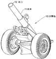
迫撃砲は、砲弾を概ね40゜以上の仰角で発射し、やまなりの弾道(曲射弾道)を描く砲であり、主として歩兵部隊の火力支援を目的として装備される。迫撃砲は、歩兵部隊が直接携行することもあれば、図1に示すように、トラックや牽引車などで牽引される牽引砲の形態で使用されることもある。 A mortar is a gun that fires bullets at an elevation angle of approximately 40 ° or more and draws a round trajectory (curved trajectory), and is equipped mainly for the purpose of supporting the firepower of infantry units. The mortar can be carried directly by an infantry unit, or it can be used in the form of a tow gun that is towed by a truck or a tow vehicle as shown in FIG.
図1に示す従来の迫撃砲110に砲弾20を装填するには、その砲身111の砲口112(砲の前方)から、図2に示す砲弾20を手で滑り込ませることにより行う。 The conventional mortar 110 shown in FIG. 1 is loaded with the cannonball 20 by sliding the cannonball 20 shown in FIG. 2 by hand from the muzzle 112 (front of the gun) of the barrel 111.
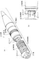
迫撃砲110に使用される砲弾20は、同図2に示すように、砲身111の砲口112(砲の前方)側の弾頭部21と、砲身111の砲尾(砲の後方)側の発射薬部22とから構成されており、発射薬部22は、弾頭部21に係合部材としてのクリップ23によって係合されている。
As shown in FIG. 2, the shell 20 used in the mortar 110 includes a bullet head 21 on the muzzle 112 (front side of the gun) side of the gun barrel 111 and a stern (rear side of the gun) side of the gun barrel 111. The projecting
迫撃砲110は、ライフル砲であり、砲身111の内壁には、ライフリング加工が施され、砲弾20に回転を与えるための施条溝(螺旋状の溝)が形成されている。一方、砲弾20の弾頭部21の後部外周には、弾帯24が円環状に形成されており、弾帯24には、砲身111側の施条溝に噛み合う突起25が形成されている。
The mortar 110 is a rifle, and the inner wall of the barrel 111 is rifle-processed to form a grooving groove (spiral groove) for rotating the cannonball 20. On the other hand, a bullet band 24 is formed in an annular shape on the outer periphery of the rear portion of the bullet head 21 of the cannonball 20, and a
砲弾20を砲口112から投入するに際し、弾頭部21を手で保持し弾頭部21の弾帯24の突起25が砲身111側の施条溝に噛み合うように調整する。そして、砲弾20が砲身111に投入されると、砲身111の底部にある撃針が砲弾20の発射薬部22に作用することで発射薬に点火する。これにより発射薬が燃焼し、高温高圧のガスが発生し、この高温高圧のガスによって、砲弾20が発射される。この際、砲弾20は、砲身111内で施条溝に倣って旋転し、回転力が付与されて砲口112から発射される。このため砲弾20は、安定して飛翔する。
When the cannonball 20 is introduced from the muzzle 112, the bullet head 21 is held by hand, and the
なお、従来、こうした迫撃砲20を自走砲として自走車両に搭載したものがあるが、この場合も上述した牽引砲と同じく、砲弾20の弾頭部21を手で保持し、砲口112から投入するというものである。 Conventionally, there is one in which such a mortar 20 is mounted on a self-propelled vehicle as a self-propelled gun, but in this case as well, the warhead 21 of the cannonball 20 is held by hand and the muzzle 112 is removed from the muzzle 112. It is to throw in.
ところが、防御、安全のため、迫撃砲用の砲弾20を車体内の砲尾から装填したいとの要請がある。既存の砲尾装填型迫撃砲搭載車両は、滑腔砲であり、砲身には上述した施条溝は形成されておらず、砲弾にも突起は形成されていない。砲弾には後部に安定翼が形成されており、砲弾は砲身内を滑って発射され、安定翼によって安定して飛翔する。また、この滑腔砲用の砲弾は、図2に示す迫撃砲用の砲弾20と異なり、一体に形成されており、砲弾の後端を保持することで容易に車体内の砲尾より砲弾を装填することができる。 However, there is a demand for loading the mortar shell 20 from the breech inside the vehicle body for defense and safety. An existing turret-mounted mortar-equipped vehicle is a smooth gun, and the above-mentioned grooving groove is not formed on the barrel, and no protrusion is formed on the shell. The shell has a stable wing at the rear, and the shell is slid within the barrel and fired stably by the stable wing. Further, unlike the mortar shell 20 shown in FIG. 2, this smooth shell cannon can be easily loaded from the turret of the vehicle body by holding the rear end of the shell. can do.
下記に砲身、砲弾に関する一般技術水準を示す文献を掲げる。 Listed below are general technical standards related to gun barrels and shells.
特許文献1には、砲身に施条溝を形成するとともに、砲弾の弾帯を軟質の材料で構成して、砲弾が砲身内を移動するときに砲弾の軟質材料が砲身の施条溝に噛み込むことで、砲弾に回転力が付与されるという発明が記載されている。 In Patent Document 1, a grooving groove is formed in the gun barrel, and the bullet band of the cannonball is made of a soft material, and when the cannonball moves through the gun barrel, the soft material of the cannonball bites into the grooving groove of the gun barrel. The invention that rotational force is imparted to the shell is described.
特許文献2には、砲身に施条溝を形成するとともに、砲弾の弾帯に突起を形成して、砲弾が砲身内を移動するときに砲弾の突起が砲身の施条溝に噛み合うことで砲弾に回転力が付与されるという発明が記載されている。 In Patent Document 2, a grooving groove is formed in the gun barrel, and a projection is formed in the shell of the shell, and when the shell moves through the gun barrel, the projection of the shell engages with the grooving groove of the gun barrel. Describes an invention in which a rotational force is applied.
特許文献3には、砲身に施条溝を形成するとともに、砲弾の弾帯を軟質(銅合金)の材料で構成して、砲弾を砲身の砲尾から装填し、砲弾が砲身内を移動するときに砲弾の軟質材料が砲身の施条溝に噛み込むことで、砲弾に回転力が付与されるという発明が記載されている。 In Patent Document 3, a grooving groove is formed in the gun barrel, the bullet band of the bullet is made of a soft (copper alloy) material, the bullet is loaded from the turret of the gun barrel, and the bullet moves in the barrel. There is a description of an invention in which a rotational force is imparted to a cannonball when a soft material of the cannonball sometimes bites into a ridge groove of a gun barrel.
また、上記特許文献1〜3には、砲弾が、図2に示す迫撃砲用の砲弾であるとの記述はない。 Further, Patent Documents 1 to 3 do not describe that the shell is a mortar shell shown in FIG.
特許文献4は、砲弾と発射薬が別体の分離装填弾を対象としており、図2に示す迫撃用の砲弾であるとの記述はない。特許文献4には、砲身の砲尾に発射薬を案内するトレイを設け、トレイを介して発射薬を装填するという発明が記載されている。
ところが、図2に示す迫撃砲用の砲弾20を、仮に車両内の砲身111の砲尾から装填しようとすると、発射薬部22を保持して、弾頭部21の突起25を砲身111内の施条溝に合わせるように、装填せざるを得ない。ここで、発射薬部22は弾頭部21に係合されているのみであるから、突起25を施条溝に合わせようとして発射薬部22に力を横方向に加えると(発射薬部22を捻ると)、発射薬部22が弾頭部21から外れるおそれがある。しかも、砲身111の施条溝は、砲尾にあっては、閉鎖機が装着されるスペースを確保するために奥まった場所にあり、施条溝に砲弾20の突起25を合わせにくい。このため砲弾20の装填に困難をきわめ、砲弾20の投射を迅速に行えないおそれがある。
However, if the mortar shell 20 shown in FIG. 2 is to be loaded from the stern of the barrel 111 in the vehicle, the
本発明は、こうした実状に鑑みてなされたものであり、迫撃砲を砲身の砲尾から装填するに際して容易に、早く行えるようにすることを解決課題とするものである。 The present invention has been made in view of such circumstances, and an object of the present invention is to make it easy and quick to load a mortar from a breech turret.
第1発明は、
迫撃砲に砲弾を装填する迫撃砲の装填装置において、
迫撃砲の砲身の内壁には、砲弾に回転を与えるための施条溝が形成され、
砲弾は、弾頭部と当該弾頭部に係合部材を介して係合される発射薬部とからなり、
砲弾の弾頭部には、前記施条溝に噛み合う突起が形成され、
迫撃砲の砲尾には、当該砲尾から砲弾を迫撃砲の砲身内に案内するガイドが設けられていること
を特徴とする。
The first invention is
In a mortar loading device that loads a mortar shell,
On the inner wall of the mortar barrel, a grooving groove is formed to give rotation to the shell,
The cannonball consists of a bullet head and a propellant part engaged with the bullet head via an engagement member,
On the warhead of the shell, a protrusion is formed that meshes with the grooving groove,
The mortar stern is provided with a guide for guiding the shell from the stern into the barrel of the mortar.
第2発明は、
迫撃砲に砲弾を装填する迫撃砲の装填装置において、
迫撃砲の砲身の内壁には、砲弾に回転を与えるための施条溝が形成され、
砲弾は、弾頭部と当該弾頭部に係合部材を介して係合される発射薬部とからなり、
砲弾の弾頭部には、前記施条溝に噛み合う突起が形成され、
迫撃砲の砲尾には、当該砲尾から砲弾を迫撃砲の砲身内に案内するガイドであって、砲身の内壁の施条溝に連続してつながる溝が形成されたガイドが設けられていること
を特徴とする。
The second invention is
In a mortar loading device that loads a mortar shell,
On the inner wall of the mortar barrel, a grooving groove is formed to give rotation to the shell,
The cannonball consists of a bullet head and a propellant part engaged with the bullet head via an engagement member,
On the warhead of the shell, a protrusion is formed that meshes with the grooving groove,
The mortar stern is provided with a guide that guides the shell from the stern into the barrel of the mortar, and is formed with a groove that is continuously connected to the ridge groove on the inner wall of the turret. It is characterized by this.
第3発明は、第1発明または第2発明において、
前記砲身と、前記ガイドは別体の部材であり、前記砲身と前記ガイドのそれぞれには嵌合部が形成されていること
を特徴とする。
The third invention is the first invention or the second invention,
The gun barrel and the guide are separate members, and a fitting portion is formed on each of the gun barrel and the guide.
第4発明は、
迫撃砲に砲弾を装填する迫撃砲の装填装置において、
砲弾の発射薬部には、焼尽材料で構成された位置決め用のストッパが設けられ、
迫撃砲の砲身の内壁の砲尾側には、当該砲尾から砲弾を装填した際に、前記位置決め用のストッパが突き当たる段差が形成されていること
を特徴とする。
The fourth invention is
In a mortar loading device that loads a mortar shell,
The projectile part of the shell is provided with a positioning stopper made of burnout material,
On the breech side of the inner wall of the mortar barrel, a step is formed in which the positioning stopper abuts when a bullet is loaded from the breech.
第5発明は、
迫撃砲に砲弾を装填する迫撃砲の装填装置において、
砲弾の発射薬部は、段差が形成されたアタッチメントで覆われ、かつ当該アタッチメントは砲弾の弾頭部に接合され、
迫撃砲の砲身の内壁の砲尾側には、当該砲尾から砲弾を装填した際に、前記アタッチメントの段差が突き当たる段差が形成されていること
を特徴とする。
The fifth invention
In a mortar loading device that loads a mortar shell,
The projectile part of the shell is covered with an attachment with a step, and the attachment is joined to the bullet head of the shell,
On the breech side of the inner wall of the barrel of the mortar, a step is formed in which the step of the attachment hits when a bullet is loaded from the breech.
第6発明は、
迫撃砲に砲弾を装填する迫撃砲の装填装置において、
前記迫撃砲は、当該迫撃砲の砲尾が車体内に位置されるように、車両に搭載され、
迫撃砲の砲身の内壁には、砲弾に回転を与えるための施条溝が形成され、
砲弾は、弾頭部と当該弾頭部に係合部材を介して係合される発射薬部とからなり、
砲弾の弾頭部には、前記施条溝に噛み合う突起が形成され、
砲弾は、迫撃砲の砲尾から装填されること
を特徴とする。
The sixth invention
In a mortar loading device that loads a mortar shell,
The mortar is mounted on the vehicle so that the mortar of the mortar is positioned in the vehicle body,
On the inner wall of the mortar barrel, a grooving groove is formed to give rotation to the shell,
The cannonball consists of a bullet head and a propellant part engaged with the bullet head via an engagement member,
On the warhead of the shell, a protrusion is formed that meshes with the grooving groove,
Cannonballs are loaded from the mortar stern.
第7発明は、第6発明において、
迫撃砲の砲尾には、当該砲尾から砲弾を迫撃砲の砲身内に案内するガイドが設けられていること
を特徴とする。
A seventh invention is the sixth invention,
The mortar stern is provided with a guide for guiding the shell from the stern into the barrel of the mortar.
第1発明によれば、図5、図8に示すように、迫撃砲210の砲身211の内壁には、砲弾20に回転を与えるための施条溝214が形成されている。砲弾20は、図2に示すように、弾頭部21と当該弾頭部21に係合部材23を介して係合される発射薬部22とからなっている。砲弾20の弾頭部21には、施条溝214に噛み合う突起25が形成されている。迫撃砲の211砲尾213には、当該砲尾213から砲弾20を迫撃砲210の砲身211内に案内するガイド220が設けられている。
According to the first aspect of the invention, as shown in FIGS. 5 and 8, the inner wall of the
第1発明によれば、迫撃砲210の砲尾213に、砲尾213から砲弾20を砲身211内に案内するガイド220を設けるようにしたため、砲弾20の発射薬部22を保持することなく、砲弾20の硬い弾頭部21を保持して、ガイド220上に載置することができる。このため砲弾20の弾頭部21が発射薬部22から外れることがなく容易に装填作業を行うことができる。また砲弾20をガイド220に載せて砲弾20を押し込むだけで、砲身211内に砲弾20が案内移動されるため、奥まった場所にある砲身211内の施条溝214に砲弾20の突起25を合わせる面倒な作業も不要となる。
According to the first invention, since the guide 220 for guiding the shell 20 from the breech 213 into the
このように第1発明によれば、砲弾20の装填作業を迅速かつ容易に行うことができるようになる。 As described above, according to the first aspect, the loading operation of the cannonball 20 can be performed quickly and easily.
また、第2発明では、第1発明の構成に加えて、更に、ガイド220の溝221を、砲身211の内壁の施条溝214に連続してつながるように形成したので、砲弾20をガイド220上から砲身211内に円滑に投入することができる。
Further, in the second invention, in addition to the structure of the first invention, the
また、第3発明では、第1発明の構成あるいは第2発明の構成に加えて、更に、砲身211と、ガイド220を別体の部材とし、砲身211とガイド220のそれぞれに嵌合部(図6、図7)を形成したので、両者の溝同士の位置決めを正確かつ容易に行え、ガイド220の脱着作業を迅速かつ容易に行うことができる。
In the third invention, in addition to the structure of the first invention or the structure of the second invention, the
また、第4発明では、砲弾20の発射薬部22に、焼尽材料で構成された位置決め用のストッパ28を設け、砲身211の後端に、砲尾213から砲弾20を装填した際に、位置決め用ストッパ28が突き当たる段差219を形成したので、砲弾装填位置の位置決めを正確かつ容易に行うことができる。すなわち、迫撃砲210を車両200に搭載した場合、砲身211を俯角方向に傾斜させて射撃を行うことがある。このように砲身211を俯角方向に傾斜させた場合であっても、ストッパ28は段差219に当接したまま砲身211から抜け落ちることがなく正確な装填位置を維持できる。また、ストッパ28が段差219に当接した位置で砲弾20が装填位置が定まるため、撃針と砲弾20との相対位置が正確に定まり、確実に撃針によって発射薬26を点火することができる。また、ストッパ28は、焼尽材料で構成されるため、砲弾20の発射に伴い燃え尽くされ砲身211内に残ることがない。このため発射毎に砲身211内を清掃する作業が不要で連続射撃を行う際の作業効率が向上する。なお、第4発明は、突起25が設けられた砲弾20に、更にストッパ28が装着される場合のみのみならず、ストッパ28が、突起25が設けられていない(たとえば軽合金等の柔らかい材質の弾帯を備えた)砲弾に装着される場合も含む。
In the fourth aspect of the invention, when the projecting
第5発明によれば、図9に示すように、砲弾20の発射薬部22を覆い弾頭部21に接合されるアタッチメント30を、砲弾20に装着するようにしたので、砲弾20を砲尾213から装填する作業を、ガイド220を使用することなく容易にかつ迅速に行うことができる。なお、第5発明は、突起25が設けられた砲弾20に、更にアタッチメント30が装着される場合のみのみならず、アタッチメント30が、突起25が設けられていない(たとえば軽合金等の柔らかい材質の弾帯を備えた)砲弾に装着される場合も含む。
According to the fifth aspect of the invention, as shown in FIG. 9, the attachment 30 that covers the
第6発明によれば、図3、図5、図8に示すように、迫撃砲210の砲尾213が車体201内に位置されるように、車両200に搭載するようにして、従来の迫撃砲110に使用されている砲弾と同じ砲弾20(図2)を車体201内で砲尾213から装填するようにしたため、砲弾の共通化によりコストを飛躍的に低減することができる。そして、砲弾20を、車体201内で安全に防護された状態で装填作業を行うことができるため、作業員が敵からの攻撃に晒されることがない。
According to the sixth invention, as shown in FIGS. 3, 5, and 8, the conventional mortar is mounted on the vehicle 200 such that the breech 213 of the mortar 210 is positioned in the
第7発明では、第6発明の構成に加えて第1発明と同様にガイド220を設けるようにしたので、砲弾20の装填作業を容易にかつ迅速に行うことができる。 In the seventh invention, in addition to the structure of the sixth invention, the guide 220 is provided in the same manner as in the first invention, so that the loading operation of the cannonball 20 can be performed easily and quickly.
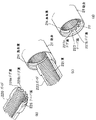
図3は、実施形態の装置の全体構成を示す。 FIG. 3 shows the overall configuration of the apparatus according to the embodiment.
すなわち、車両200には、図1に示す迫撃砲110と同様の構成の迫撃砲210が搭載される。迫撃砲210の砲身111は、砲口212が、車体201外に位置され、砲尾213が、車体201内に位置されるように、車両200に装着されている。
That is, a mortar 210 having the same configuration as the mortar 110 shown in FIG. The barrel 111 of the mortar 210 is mounted on the vehicle 200 such that the muzzle 212 is positioned outside the
実施形態の迫撃砲210に使用される砲弾20は、図2に示すように、従来の図1の迫撃砲110に使用される砲弾20と同一のものである。 The cannonball 20 used for the mortar 210 of the embodiment is the same as the cannonball 20 used for the conventional mortar 110 of FIG. 1, as shown in FIG.
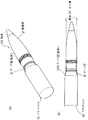
図2(a)は砲弾20を斜視図にて示し、図2(b)は砲弾20の弾頭部211と発射薬部22との係合部を拡大して示している。
2A is a perspective view of the cannonball 20, and FIG. 2B is an enlarged view of an engaging portion between the
図2(a)、(b)に示すように、砲弾20は、砲身211の砲口112(砲の前方)側の弾頭部21と、砲身211の砲尾(砲の後方)側の発射薬部22とから構成されている。発射薬部22は、軸27と、この軸27の外周に装着される複数の円環状の発射薬26とからなる。なお、発射薬26は、砲弾20を飛翔させたい距離に応じて、装着される個数を調整する。発射薬部22の軸27は、弾頭部21に係合部材としてのクリップ23によって係合されている。このクリップ23による結合力は、発射薬26の燃焼圧で外れる程度の大きさに調整されている。砲弾20の弾頭部21の後部外周には、弾帯24が円環状に形成されており、弾帯24には、砲身211側の後述する施条溝214に噛み合う突起25が形成されている。なお弾帯24は、弾頭部21と一体に形成されており、弾頭部21と同じ材質(たとえば鉄)で構成されている。なお、図2では弾帯24を弾頭部21の周方向の全体にわたり帯状に形成しているが、もちろん弾頭部21の周方向の一部に形成してもよい。
As shown in FIGS. 2 (a) and 2 (b), the shell 20 includes a bullet head 21 on the muzzle 112 (front of the gun) side of the
ただし、従来の迫撃砲110用の砲弾20と異なり、実施形態の砲弾20の発射薬部22の軸27には、ストッパ28が装着されている。ストッパ28は、発射薬26の後方に装着される。
However, unlike the cannonball 20 for the conventional mortar 110, a stopper 28 is attached to the shaft 27 of the
ストッパ28の形状は、図4に示される。同図4に示すように、ストッパ28は、発射薬部22の軸27に嵌合する開口部28aを有している。ストッパ28は、発射薬26の燃焼によって焼尽されるセルロース、紙(段ボール紙)等の焼尽材料で構成されている。ストッパ28は、発射薬部22の軸27に嵌合されて後述するガイド220に載置された際に、ガイド載置面側(下側)では弾頭部21の外径を超えずにガイド載置面に対向する側(上側)では弾頭部21の外径を超える形状、大きさに形成されている。
The shape of the stopper 28 is shown in FIG. As shown in FIG. 4, the stopper 28 has an opening 28 a that fits into the shaft 27 of the
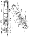
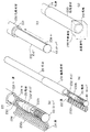
図5(a)は、車両200に搭載される迫撃砲210の全体構成を断面図にて示しており、図5(b)は迫撃砲210の砲尾213付近を拡大して示している。 5A is a sectional view showing the overall configuration of the mortar 210 mounted on the vehicle 200, and FIG. 5B is an enlarged view of the vicinity of the breech 213 of the mortar 210. FIG.
これら図5(a)、(b)に示すように、迫撃砲210は、大きくは、砲身211と、砲身211の後部に接続された砲尾部材222と、砲尾部材222の後端、つまり砲尾213の口を閉塞する閉鎖機215と、砲尾213から砲弾20を砲身211内に案内するガイド220とから構成されている。
As shown in FIGS. 5A and 5B, the mortar 210 is roughly composed of a
砲身211の内壁には、ライフリング加工が施され、砲弾20に回転を与えるための施条溝214(螺旋状の溝)が形成されている。
On the inner wall of the
砲身211の内壁の後部には、後方に行くほど径が大きくなるテーパ面223が形成されている。
A
砲尾部材222は、砲弾20が砲尾213から挿通される部材であり、内壁の後部には、閉鎖機215が螺着するスプライン218が形成されている。砲尾部材222は、砲身211との接続箇所で、その内径D1が、砲身211の後端の内径D2よりも大きくなるように形成されている。このため砲身211と砲尾部材222との接続箇所で内壁に、後方の径が前方の径よりも大きくなる段差219が形成される。この段差219は、砲弾20が砲尾213から装填された際に、砲弾20に装着されたストッパ28が突き当たる大きさ、形状に形成されている。
The
ガイド220は、砲弾20全体を載置できる大きさ、形状のトレーであり、たとえば断面が、砲弾20の直径に応じた曲率を有する円弧状に形成されている。ガイド220の砲弾載置面には、砲身211の内壁の施条溝214に連続してつながる螺旋状の溝221が形成されている。この溝221は、砲弾20がガイド220上に載置されたとき、砲弾20の突起25と噛み合う形状、大きさに形成されている。
The guide 220 is a tray having a size and shape on which the entire shell 20 can be placed. For example, the cross section is formed in an arc shape having a curvature corresponding to the diameter of the shell 20. On the shell mounting surface of the guide 220, a
閉鎖機215は、レバー217の操作によって、砲尾部材222の後端(砲尾213)の口を閉塞し、また解放することができるように、砲尾部材222に取り付けられている。
The closing machine 215 is attached to the
閉鎖機215には、砲尾部材222のスプライン218に螺着するスプライン216が形成されている。レバー217を操作して、閉鎖機215のスプライン216と砲尾部材222のスプライン218とを螺着させることで、砲尾部材222の後端(砲尾213)の口を閉塞することができ、また、レバー217を操作して、閉鎖機215のスプライン216と砲尾部材222のスプライン218との螺着状態を解除することで、砲尾部材222の後端(砲尾213)の口を解放することができる。
The closing machine 215 is formed with a
図6は、砲身211とガイド220との嵌合状態を説明する図である。
FIG. 6 is a diagram illustrating a fitting state between the
図6(a)は砲身211の後部を斜視図にて示しており、図6(b)はガイド220の前部を斜視図にて示しており、図6(c)は砲身211とガイド220とが嵌合した状態を示している。これら図6に示すように、砲身211と、ガイド222は別体の部材であり、砲身211とガイド220のそれぞれには嵌合部224、225が形成されている。すなわち、ガイド220には、両者の嵌合をスムーズに行うために、砲身211のテーパ面223に倣うテーパ面226が形成されている。砲身211の嵌合面には、複数のピン孔224が形成されており、一方、ガイド220の嵌合面には、複数のピン225が形成されており、ピン225がピン孔224に嵌合することで、砲身211とガイド220とが接続、固定される。また、ピン225がピン孔224が嵌合することで、ガイド220の溝221と砲身211の施条溝214との位置決めが行われ、両溝を連続してつなげることができる。
6A is a perspective view of the rear part of the
図7は、図6とは別の嵌合部材を用いた場合の砲身211とガイド220との嵌合状態を説明する図である。
FIG. 7 is a view for explaining a fitting state between the
図7(a)は砲身211の後部を斜視図にて示しており、図7(b)はガイド220の前部を斜視図にて示しており、図7(c)は砲身211とガイド220とが嵌合した状態を示している。
7A shows a rear portion of the
ガイド220には、両者の嵌合をスムーズに行うために、砲身211のテーパ面223′に倣うテーパ面226′が形成されている。砲身211の嵌合面には、複数のドグ歯227a、ドグ溝227bが形成されており、一方、ガイド220の嵌合面には、複数のドグ歯228a、ドグ溝228bが形成されており、ドグ歯227aがドグ溝228bに嵌合し、ドグ歯228aがドグ溝227bが嵌合することで、砲身211とガイド220とが接続、固定される。また、ドグ歯227aがドグ溝228bに嵌合し、ドグ歯228aがドグ溝227bが嵌合することで、ガイド220の溝221と砲身211の施条溝214との位置決めが行われ、両溝を連続してつなげることができる。
The guide 220 is formed with a
つぎに、砲弾20を迫撃砲210に装填する動作について説明する。 Next, the operation of loading the munition 20 into the mortar 210 will be described.
まず、図5に示すように、レバー217が操作され、閉鎖機215と砲尾部材222との螺着状態が解除され、砲尾部材222の後端つまり砲尾213から砲弾20を投入できる状態にされる。
First, as shown in FIG. 5, the lever 217 is operated to release the screwed state between the closing machine 215 and the
つぎに、ガイド220を砲身211に嵌合し、図6(c)ないしは図7(c)の状態にする。
Next, the guide 220 is fitted into the
つぎに砲弾20がガイド220上に載置される。この際、弾頭部21を手で保持し弾頭部21の弾帯24の突起25がガイド220側の溝221に噛み合うように調整する。そして、押し込み棒300を用いて砲弾20の後端を押すことで、砲弾20をガイド220上で移動させる。砲弾20は、溝221(螺旋状の溝)に倣い、回転しながらガイド220上を移動する。
Next, the cannonball 20 is placed on the guide 220. At this time, the warhead 21 is held by hand, and the
ガイド220の溝221と砲身211の施条溝214とは連続してつながっているため、砲弾20は、ガイド220から砲身211にスムーズに移動する。砲弾20は、施条溝214(螺旋状の溝)に倣い、回転しながら砲身211内を移動する。
Since the
図8(a)、(b)は砲弾20が装填された状態を示す。図8(a)は断面図で、図8(b)は斜視図である。 FIGS. 8A and 8B show a state in which the cannonball 20 is loaded. FIG. 8A is a cross-sectional view, and FIG. 8B is a perspective view.
同図8に示すように、砲弾20のストッパ28が砲身211と砲尾部材222との段差219に当接されると、押し込み棒300を砲弾20の後端から後方へ引き寄せる。つぎにガイド220と砲身211との嵌合状態(図6(c)ないしは図7(c))を解除し、ガイド220を砲尾213から取り除く。つぎに、レバー217が操作され、閉鎖機215のスプライン216と砲尾部材222のスプライン218とを螺着させて、砲尾213を閉塞する。
As shown in FIG. 8, when the stopper 28 of the cannonball 20 is brought into contact with the step 219 between the
このように砲弾20が砲身211に投入されると、撃針が砲弾20の発射薬部22に作用し、発射薬26に点火される。これにより発射薬26が燃焼し、高温高圧のガスが発生し、この高温高圧のガスによって、砲弾20が発射される。この際、砲弾20は、砲身211内で施条溝214に倣って旋転し、回転力が付与されて砲口112から発射される。このため砲弾20(の弾頭部21)は、安定して飛翔する。なお、発射薬部22は、弾頭部21とクリップ23を介して係合されているのみであるため、発射薬26の燃焼圧によって弾頭部21から外れて、落下する。また、ストッパ28は焼尽材料で構成されているため、発射薬26の燃焼により燃え尽くされる。
When the cannonball 20 is inserted into the
以上説明したように、本実施形態によれば、迫撃砲210の砲尾213に、砲尾213から砲弾20を砲身211内に案内するガイド220を設けるようにしたため、砲弾20の発射薬部22を保持することなく、砲弾20の硬い弾頭部21を保持して、ガイド220上に載置することができる。このため砲弾20の弾頭部21が発射薬部22から外れることがなく容易に装填作業を行うことができる。また砲弾20をガイド220に載せて砲弾20を押し込むだけで、砲身211内に砲弾20が案内移動されるため、奥まった場所にある砲身211内の施条溝214に砲弾20の突起25を合わせる面倒な作業も不要となる。
As described above, according to the present embodiment, since the guide 220 for guiding the shell 20 from the breech 213 into the
このように本実施形態の装置では、砲弾20の装填作業を迅速かつ容易に行うことができるようになる。 As described above, in the apparatus of the present embodiment, the loading operation of the cannonball 20 can be performed quickly and easily.
また、実施形態では、ガイド220の溝221を、砲身211の内壁の施条溝214に連続してつながるように形成したので、砲弾20をガイド220上から砲身211内に円滑に投入することができる。なお、ガイド220の溝221は、必ずしも、砲身211の内壁の施条溝214に連続してつながるように形成する必要はなく、砲弾20を円滑に砲身211内に投入できることができるのであれば、溝221と施条溝214とは不連続であったり、ずれがあったりしてもよい。
In the embodiment, the
また、実施形態では、砲身211と、ガイド220を別体の部材とし、砲身211とガイド220のそれぞれに嵌合部(図6、図7)を形成したので、両者の溝同士の位置決めを正確かつ容易に行え、ガイド220の脱着作業を迅速かつ容易に行うことができる。
Further, in the embodiment, the
また、実施形態では、砲弾20の発射薬部22に、焼尽材料で構成された位置決め用のストッパ28を設け、砲身211の後端に、砲尾213から砲弾20を装填した際に、位置決め用ストッパ28が突き当たる段差219を形成したので、砲弾装填位置の位置決めを正確かつ容易に行うことができる。すなわち、迫撃砲210を車両200に搭載した場合、砲身211を俯角方向に傾斜させて射撃を行うことがある。このように砲身211を俯角方向に傾斜させた場合であっても、ストッパ28は段差219に当接したまま砲身211から抜け落ちることがなく正確な装填位置を維持できる。また、ストッパ28が段差219に当接した位置で砲弾20が装填位置が定まるため、撃針と砲弾20との相対位置が正確に定まり、確実に撃針によって発射薬26を点火することができる。また、ストッパ28は、焼尽材料で構成されるため、砲弾20の発射に伴い燃え尽くされ砲身211内に残ることがない。このため発射毎に砲身211内を清掃する作業が不要で連続射撃を行う際の作業効率が向上する。
Further, in the embodiment, a positioning stopper 28 made of a burnout material is provided on the
以上のように本実施形態の装置は、迫撃砲210の砲尾213が車体201内に位置されるように、車両200に搭載するようにして、従来の迫撃砲110に使用されている砲弾と同じ砲弾20を車体201内で砲尾213から装填するようにしたため、砲弾の共通化によりコストを飛躍的に低減することができる。そして、砲弾20を、車体201内で安全に防護された状態で装填作業を
行うことができるため、作業員が敵からの攻撃に晒されることがない。
As described above, the apparatus according to the present embodiment is mounted on the vehicle 200 so that the breech 213 of the mortar 210 is positioned in the
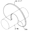
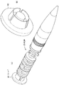
上述した実施形態では、砲弾20の発射薬部22の軸27に、図4に示す板状のストッパ28を装着しているが、図4に示す板状のストッパ28の代わりに、図9(a)、(b)に示す筒状のアタッチメント30をストッパ28と同等の機能のものとして使用してもよい。
In the embodiment described above, the plate-like stopper 28 shown in FIG. 4 is attached to the shaft 27 of the
図9(a)は、アタッチメント30が装着された砲弾20の斜視図を示し、図9(b)は、アタッチメント30が装着された砲弾20が砲身211′に装填された状態を示す。
FIG. 9A shows a perspective view of the cannonball 20 to which the attachment 30 is attached, and FIG. 9B shows a state in which the cannonball 20 to which the attachment 30 is attached is loaded in the
すなわち、アタッチメント30は、保持が容易で、発射薬部22の全体を覆うことができる形状(たとえば筒状)、材質、大きさで構成されている。
That is, the attachment 30 is configured with a shape (for example, a cylindrical shape), a material, and a size that can be easily held and can cover the
まず、砲弾20の飛翔距離に応じた数の発射薬26が発射薬部22の軸27に取り付けられ、その後、アタッチメント30が発射薬部22全体に被せられる。そして、アタッチメント30の弾頭部21との接合箇所で、「かしめ」による加工が施され、前方に行くほど径が小さくなるテーパ面31(段差)が形成されて、アタッチメント30が弾頭部21に接合される。つぎに、アタッチメント30を保持して、砲弾20が砲身211′内に直接装填される。アタッチメント30は、弾頭部21に接合されているため、ガイド220を使用せずに装填作業を行った場合であっても、発射薬部22が弾頭部21から外れることがない。
First, a number of propellants 26 corresponding to the flight distance of the cannonball 20 are attached to the shaft 27 of the
ただし、この実施例の砲身211′は、前述した図5に示す砲身211と異なり、図9(b)に示すように、砲身211′の内壁には、従来の薬きょうを用いた火砲の砲身と同様なテーパ面229(段差)が形成されている。この砲身211′のテーパ面229は、砲弾20のアタッチメント30のテーパ面31に倣う形状に形成されている。砲弾20のアタッチメント30のテーパ面31が砲身211′のテーパ面229に突き当たった位置で、砲弾装填位置が定まる。また、このように砲弾20のアタッチメント30のテーパ面31が砲身211′のテーパ面229に突き当たるため、砲身211′が俯角方向に傾斜した場合であっても、砲弾20が砲身211′から抜け落ちることもない。また、砲弾20と撃針との相対位置が正確に定まり、撃針により確実に発射薬26を点火することができる。
However, the
このように図9に示す実施例では、砲弾20の発射薬部22を覆い弾頭部21に接合されるアタッチメント30を、砲弾20に装着するようにしたので、砲弾20を砲尾213から装填する作業を、ガイド220を使用することなく容易にかつ迅速に行うことができる。
As described above, in the embodiment shown in FIG. 9, the attachment 30 that covers the
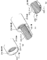
また、図10(a)に示すように、図4に示すストッパ28の代わりに、図10(b)に示す円板状のストッパ40を、砲弾20の後端、つまり発射薬部22の後端に取り付けてもよい。
Further, as shown in FIG. 10 (a), instead of the stopper 28 shown in FIG. 4, a disc-
図11を参照して、図5に示すガイド220とは別のガイド232を用いて、ストッパ40が装着された砲弾20を装填する装置について説明する。
With reference to FIG. 11, an apparatus for loading the cannonball 20 to which the
図11(a)は、装置の全体構成の外観を斜視図で示しており、大きくは、砲身211と、砲身211の後部に接続される砲尾部材230と、砲尾部材230の孔内に挿入される筒状のガイド232とから構成されている。筒状のガイド232は、縦(長手方向)断面で2分割されたガイド部材232a、232bで構成されている。
FIG. 11A is a perspective view showing the external appearance of the overall configuration of the apparatus. In general, a
砲身211は、後端に至るまで施条溝214が形成されている。砲身211の内径とガイド232の内径とは等しく、ガイド232の内壁には、図5に示すガイド220の溝221と同様な溝221が形成されている。砲尾部材230の内径は、ガイド232の外形とほぼ等しく、砲尾部材230の長さは、ガイド232の長さとほぼ等しい。ガイド232は、砲弾20を載せることができる長さで、かつガイド232の内径は、砲弾20の外径に応じた大きさになっている。
The
砲弾20に装着されるストッパ40の外径は、筒状のガイド232の内径よりも大きく設定されている。
The outer diameter of the
図11(b)は、ガイド232と砲尾部材230の構成を斜視図で示している。
FIG. 11B shows a configuration of the
砲尾部材232には、内壁の長手方向に沿ってキー溝231が形成されている。
A
ガイド232は、断面半円状の2分割された両ガイド部材232a、232bが蝶番等の可動部材233を介して接続されており、開閉自在となっている。ガイド232の外側の長手方向に沿って、キー溝231に歯合するキー234が形成されている。
The
つぎに砲弾20の装填作業の手順について図11(b)、(c)、(d)を順次参照して説明する。 Next, the procedure for loading the cannonball 20 will be described with reference to FIGS. 11B, 11C, and 11D sequentially.
まず、図11(b)に示すように、筒状のガイド232を開状態にして、一方のガイド部材232b上に砲弾20を載置する。この際に、弾頭部21を手で保持し弾頭部21の弾帯24の突起25がガイド部材232bの溝221に噛み合うように調整する。またストッパ40がガイド部材232bの後端面に当接するように位置決めする。
First, as shown in FIG. 11B, the
つぎに、図11(c)に示すように、ガイド232を閉状態にし、筒状となったガイド232のキー234を砲尾部材230のキー溝231に歯合させながら、ガイド232を、砲尾部材230内に挿通させる。
Next, as shown in FIG. 11C, the
図11(d)に示すように、ガイド232は、砲身211の後端に当接するまで挿通される。ガイド232のキー234を砲尾部材230のキー溝231に歯合させることで、ガイド232側の溝221と砲身211側の施条溝214との位置決めが行われる。このためガイド232が、砲身211の後端に当接する位置で、ガイド232の溝221が砲身211の施条溝214に連続してつながる。このときストッパ40の後端面は、砲尾部材230の後端面と同一面となる。
As shown in FIG. 11 (d), the
つぎに垂直鎖栓235が上昇し、砲尾部材230の後端面つまり砲尾213の口が閉塞される。
Next, the vertical chain stopper 235 is raised, and the rear end surface of the
このように砲弾20が装填されると、撃針が砲弾20の発射薬部22に作用し、発射薬26に点火される。これにより発射薬26が燃焼し、高温高圧のガスが発生し、この高温高圧のガスによって、砲弾20が発射される。この際、砲弾20は、ガイド232内で溝221に倣って旋転し、更に砲身211内で施条溝214に倣って旋転し、回転力が付与されて砲口112から発射される。このため砲弾20(の弾頭部21)は、安定して飛翔する。
When the cannonball 20 is loaded in this way, the firing pin acts on the
なお、上述した説明では、突起25が設けられた砲弾20に、更にストッパ28あるいはアタッチメント30あるいはストッパ40を装着しているが、これらストッパ28あるいはアタッチメント30あるいはストッパ40を、突起25が設けられていない(たとえば軽合金等の柔らかい材質の弾帯を備えた)砲弾に装着するような実施も可能である。
In the above description, the cannonball 20 provided with the
20 砲弾、21 弾頭部、22 発射薬部、23 クリップ(係合部材)、 25 突起、28 ストッパ、30 アタッチメント、31 テーパ面(段差)、40 ストッパ、200 車両、201 車体、210 迫撃砲、211 砲身、214 施条溝、219 段差、220 ガイド、221 溝、224 ピン孔(嵌合部)、225 ピン(嵌合部)、227a、228a ドグ歯(嵌合部)、227b、228b ドグ溝(嵌合部)、 229 テーパ面(段差) 20 shells, 21 warheads, 22 projectile parts, 23 clips (engaging members), 25 protrusions, 28 stoppers, 30 attachments, 31 taper surfaces (steps), 40 stoppers, 200 vehicles, 201 car bodies, 210 mortars, 211 Gun barrel, 214 ridge groove, 219 step, 220 guide, 221 groove, 224 pin hole (fitting part), 225 pin (fitting part), 227a, 228a dog tooth (fitting part), 227b, 228b dog groove ( Fitting part), 229 Tapered surface (step)
Claims (7)
迫撃砲の砲身の内壁には、砲弾に回転を与えるための施条溝が形成され、
砲弾は、弾頭部と当該弾頭部に係合部材を介して係合される発射薬部とからなり、
砲弾の弾頭部には、前記施条溝に噛み合う突起が形成され、
迫撃砲の砲尾には、当該砲尾から砲弾を迫撃砲の砲身内に案内するガイドが設けられていること
を特徴とする迫撃砲の装填装置。 In a mortar loading device that loads a mortar shell,
On the inner wall of the mortar barrel, a grooving groove is formed to give rotation to the shell,
The cannonball consists of a bullet head and a propellant part engaged with the bullet head via an engagement member,
On the warhead of the shell, a protrusion is formed that meshes with the grooving groove,
A mortar loading device, characterized in that the mortar breech is provided with a guide for guiding a shell from the breech into the barrel of the mortar.
迫撃砲の砲身の内壁には、砲弾に回転を与えるための施条溝が形成され、
砲弾は、弾頭部と当該弾頭部に係合部材を介して係合される発射薬部とからなり、
砲弾の弾頭部には、前記施条溝に噛み合う突起が形成され、
迫撃砲の砲尾には、当該砲尾から砲弾を迫撃砲の砲身内に案内するガイドであって、砲身の内壁の施条溝に連続してつながる溝が形成されたガイドが設けられていること
を特徴とする迫撃砲の装填装置。 In a mortar loading device that loads a mortar shell,
On the inner wall of the mortar barrel, a grooving groove is formed to give rotation to the shell,
The cannonball consists of a bullet head and a propellant part engaged with the bullet head via an engagement member,
On the warhead of the shell, a protrusion is formed that meshes with the grooving groove,
The mortar stern is provided with a guide that guides the shell from the stern into the barrel of the mortar, and is formed with a groove that is continuously connected to the ridge groove on the inner wall of the turret. A mortar loading device characterized by this.
を特徴とする請求項1または2記載の迫撃砲の装填装置。 The mortar loading apparatus according to claim 1 or 2, wherein the gun barrel and the guide are separate members, and a fitting portion is formed in each of the gun barrel and the guide.
砲弾の発射薬部には、焼尽材料で構成された位置決め用のストッパが設けられ、
迫撃砲の砲身の内壁の砲尾側には、当該砲尾から砲弾を装填した際に、前記位置決め用のストッパが突き当たる段差が形成されていること
を特徴とする迫撃砲の装填装置。 In a mortar loading device that loads a mortar shell,
The projectile part of the shell is provided with a positioning stopper made of burnout material,
A mortar loading device, characterized in that a step is formed on the breech side of the inner wall of the barrel of the mortar, on which the positioning stopper abuts when a bullet is loaded from the breech.
砲弾の発射薬部は、段差が形成されたアタッチメントで覆われ、かつ当該アタッチメントは砲弾の弾頭部に接合され、
迫撃砲の砲身の内壁の砲尾側には、当該砲尾から砲弾を装填した際に、前記アタッチメントの段差が突き当たる段差が形成されていること
を特徴とする迫撃砲の装填装置。 In a mortar loading device that loads a mortar shell,
The projectile part of the shell is covered with an attachment with a step, and the attachment is joined to the bullet head of the shell,
A mortar loading device, characterized in that a step is formed on the breech side of the inner wall of the barrel of the mortar, where a step of the attachment hits when a bullet is loaded from the breech.
前記迫撃砲は、当該迫撃砲の砲尾が車体内に位置されるように、車両に搭載され、
迫撃砲の砲身の内壁には、砲弾に回転を与えるための施条溝が形成され、
砲弾は、弾頭部と当該弾頭部に係合部材を介して係合される発射薬部とからなり、
砲弾の弾頭部には、前記施条溝に噛み合う突起が形成され、
砲弾は、迫撃砲の砲尾から装填されること
を特徴とする迫撃砲の装填装置。 In a mortar loading device that loads a mortar shell,
The mortar is mounted on the vehicle so that the mortar of the mortar is positioned in the vehicle body,
On the inner wall of the mortar barrel, a grooving groove is formed to give rotation to the shell,
The cannonball consists of a bullet head and a propellant part engaged with the bullet head via an engagement member,
On the warhead of the shell, a protrusion is formed that meshes with the grooving groove,
A mortar loading device, characterized in that the shell is loaded from the mortar breech.
を特徴とする請求項6記載の迫撃砲の装填装置。
The mortar loading device according to claim 6, wherein a guide for guiding a shell from the turret into a barrel of the mortar is provided in the mortar of the mortar.
Priority Applications (1)
| Application Number | Priority Date | Filing Date | Title |
|---|---|---|---|
| JP2004113293A JP2005299959A (en) | 2004-04-07 | 2004-04-07 | Mortar loading device |
Applications Claiming Priority (1)
| Application Number | Priority Date | Filing Date | Title |
|---|---|---|---|
| JP2004113293A JP2005299959A (en) | 2004-04-07 | 2004-04-07 | Mortar loading device |
Publications (1)
| Publication Number | Publication Date |
|---|---|
| JP2005299959A true JP2005299959A (en) | 2005-10-27 |
Family
ID=35331708
Family Applications (1)
| Application Number | Title | Priority Date | Filing Date |
|---|---|---|---|
| JP2004113293A Withdrawn JP2005299959A (en) | 2004-04-07 | 2004-04-07 | Mortar loading device |
Country Status (1)
| Country | Link |
|---|---|
| JP (1) | JP2005299959A (en) |
Cited By (8)
| Publication number | Priority date | Publication date | Assignee | Title |
|---|---|---|---|---|
| JP2009097763A (en) * | 2007-10-16 | 2009-05-07 | Ihi Aerospace Co Ltd | Flying object |
| JP2012021667A (en) * | 2010-07-12 | 2012-02-02 | Fuji Seisakusho:Kk | Gun barrel cleaning method and gun barrel cleaning device |
| TWI491843B (en) * | 2013-02-08 | 2015-07-11 | ||
| CN112042634A (en) * | 2020-06-19 | 2020-12-08 | 博德锐普(南京)科技有限公司 | Bird-scaring gun |
| CN113324434A (en) * | 2021-06-22 | 2021-08-31 | 无锡职业技术学院 | Gun carriage swinging type shell feeding device |
| CN113340152A (en) * | 2021-05-31 | 2021-09-03 | 南京理工大学 | Multilayer split type balance gun loading system and method |
| CN113916047A (en) * | 2021-11-04 | 2022-01-11 | 西安昆仑工业(集团)有限责任公司 | Artillery frame swinging type shell feeding device |
| CN117146637A (en) * | 2023-10-16 | 2023-12-01 | 南京理工大学 | A mortar dual-coordinated arm muzzle automatic loading system and method |
-
2004
- 2004-04-07 JP JP2004113293A patent/JP2005299959A/en not_active Withdrawn
Cited By (11)
| Publication number | Priority date | Publication date | Assignee | Title |
|---|---|---|---|---|
| JP2009097763A (en) * | 2007-10-16 | 2009-05-07 | Ihi Aerospace Co Ltd | Flying object |
| JP2012021667A (en) * | 2010-07-12 | 2012-02-02 | Fuji Seisakusho:Kk | Gun barrel cleaning method and gun barrel cleaning device |
| TWI491843B (en) * | 2013-02-08 | 2015-07-11 | ||
| CN112042634A (en) * | 2020-06-19 | 2020-12-08 | 博德锐普(南京)科技有限公司 | Bird-scaring gun |
| CN112042634B (en) * | 2020-06-19 | 2022-10-21 | 博德锐普(南京)科技有限公司 | Bird-scaring gun |
| CN113340152A (en) * | 2021-05-31 | 2021-09-03 | 南京理工大学 | Multilayer split type balance gun loading system and method |
| CN113340152B (en) * | 2021-05-31 | 2022-05-20 | 南京理工大学 | A multi-layer split balanced gun loading system and method |
| CN113324434A (en) * | 2021-06-22 | 2021-08-31 | 无锡职业技术学院 | Gun carriage swinging type shell feeding device |
| CN113324434B (en) * | 2021-06-22 | 2022-09-16 | 无锡职业技术学院 | Gun carriage swinging type shell feeding device |
| CN113916047A (en) * | 2021-11-04 | 2022-01-11 | 西安昆仑工业(集团)有限责任公司 | Artillery frame swinging type shell feeding device |
| CN117146637A (en) * | 2023-10-16 | 2023-12-01 | 南京理工大学 | A mortar dual-coordinated arm muzzle automatic loading system and method |
Similar Documents
| Publication | Publication Date | Title |
|---|---|---|
| RU2295100C2 (en) | Barrel assembly (modifications), weapon, method for transformation and loading of weapon | |
| KR101214057B1 (en) | Projectile | |
| JP6499649B2 (en) | Bullets for small or light weapons with projectile body | |
| US11047660B2 (en) | Muzzleloader systems | |
| US10030956B2 (en) | Muzzleloader systems | |
| JPH05502933A (en) | low energy cartridge | |
| CN1269008A (en) | Arrangement for supporting mortar shell into barrel | |
| US11668549B2 (en) | Muzzleloader systems | |
| JP2003533668A (en) | Projectile | |
| US7207275B1 (en) | Firearm projectile | |
| CA2559098A1 (en) | Safety mechanism for a rifle | |
| JP2005299959A (en) | Mortar loading device | |
| WO2018013650A1 (en) | Firearm bolt configured to prevent the firing of a conventional cartridge | |
| CN101970971B (en) | Arrangement for supporting mortar shell into breech-loading weapon barrel | |
| KR20190136686A (en) | Projectile | |
| US20080257192A1 (en) | High Muzzle Velocity Projectiles and Barrels | |
| JP2003522931A (en) | Removal of ammunition | |
| US8127684B2 (en) | Charge mount | |
| US12467727B2 (en) | Ammunition blank and corresponding bolt | |
| US12031786B1 (en) | Auto purge suppressor | |
| US9297619B1 (en) | Bullet for striking obstructed targets | |
| JP5165332B2 (en) | Flying object | |
| US20050193615A1 (en) | Combustion chamber for a muzzleloading firearm | |
| RU2422757C1 (en) | Artillery small-calibre cartridge | |
| KR20250152326A (en) | Cartridge detachable grenade and grenade launcher including the same |
Legal Events
| Date | Code | Title | Description |
|---|---|---|---|
| A300 | Withdrawal of application because of no request for examination |
Free format text: JAPANESE INTERMEDIATE CODE: A300 Effective date: 20070703 |