JP2005299956A - Heat exchanger - Google Patents
Heat exchanger Download PDFInfo
- Publication number
- JP2005299956A JP2005299956A JP2004113204A JP2004113204A JP2005299956A JP 2005299956 A JP2005299956 A JP 2005299956A JP 2004113204 A JP2004113204 A JP 2004113204A JP 2004113204 A JP2004113204 A JP 2004113204A JP 2005299956 A JP2005299956 A JP 2005299956A
- Authority
- JP
- Japan
- Prior art keywords
- refrigerant
- heat transfer
- heat exchanger
- tube
- heat
- Prior art date
- Legal status (The legal status is an assumption and is not a legal conclusion. Google has not performed a legal analysis and makes no representation as to the accuracy of the status listed.)
- Pending
Links
Images


Classifications
-
- F—MECHANICAL ENGINEERING; LIGHTING; HEATING; WEAPONS; BLASTING
- F28—HEAT EXCHANGE IN GENERAL
- F28F—DETAILS OF HEAT-EXCHANGE AND HEAT-TRANSFER APPARATUS, OF GENERAL APPLICATION
- F28F1/00—Tubular elements; Assemblies of tubular elements
- F28F1/10—Tubular elements and assemblies thereof with means for increasing heat-transfer area, e.g. with fins, with projections, with recesses
- F28F1/12—Tubular elements and assemblies thereof with means for increasing heat-transfer area, e.g. with fins, with projections, with recesses the means being only outside the tubular element
- F28F1/14—Tubular elements and assemblies thereof with means for increasing heat-transfer area, e.g. with fins, with projections, with recesses the means being only outside the tubular element and extending longitudinally
- F28F1/16—Tubular elements and assemblies thereof with means for increasing heat-transfer area, e.g. with fins, with projections, with recesses the means being only outside the tubular element and extending longitudinally the means being integral with the element, e.g. formed by extrusion
-
- F—MECHANICAL ENGINEERING; LIGHTING; HEATING; WEAPONS; BLASTING
- F28—HEAT EXCHANGE IN GENERAL
- F28D—HEAT-EXCHANGE APPARATUS, NOT PROVIDED FOR IN ANOTHER SUBCLASS, IN WHICH THE HEAT-EXCHANGE MEDIA DO NOT COME INTO DIRECT CONTACT
- F28D7/00—Heat-exchange apparatus having stationary tubular conduit assemblies for both heat-exchange media, the media being in contact with different sides of a conduit wall
- F28D7/0041—Heat-exchange apparatus having stationary tubular conduit assemblies for both heat-exchange media, the media being in contact with different sides of a conduit wall the conduits for only one medium being tubes having parts touching each other or tubes assembled in panel form
-
- F—MECHANICAL ENGINEERING; LIGHTING; HEATING; WEAPONS; BLASTING
- F28—HEAT EXCHANGE IN GENERAL
- F28D—HEAT-EXCHANGE APPARATUS, NOT PROVIDED FOR IN ANOTHER SUBCLASS, IN WHICH THE HEAT-EXCHANGE MEDIA DO NOT COME INTO DIRECT CONTACT
- F28D7/00—Heat-exchange apparatus having stationary tubular conduit assemblies for both heat-exchange media, the media being in contact with different sides of a conduit wall
- F28D7/16—Heat-exchange apparatus having stationary tubular conduit assemblies for both heat-exchange media, the media being in contact with different sides of a conduit wall the conduits being arranged in parallel spaced relation
Landscapes
- Engineering & Computer Science (AREA)
- Physics & Mathematics (AREA)
- Thermal Sciences (AREA)
- Mechanical Engineering (AREA)
- General Engineering & Computer Science (AREA)
- Geometry (AREA)
- Heat-Exchange Devices With Radiators And Conduit Assemblies (AREA)
- Air-Conditioning For Vehicles (AREA)
Abstract
【課題】 伝熱フィンを外周に有した冷媒チューブをハウジング内に複数備えた熱交換器の製造を容易にする。
【解決手段】 蓄冷熱交換器11は、蓄冷材13で充満されたハウジング15と、ハウジング15内を互いに平行に延び内部を冷媒が流れる複数の冷媒チューブ17と、伝熱面拡大のために各冷媒チューブ17の外周に設けられた伝熱フィン27とを備える。さらに、冷媒チューブ17の長手軸線と垂直な方向における伝熱フィン27の先端から側方に突出するガイドリブ31が伝熱フィン27の先端に沿って設けられている。
【選択図】 図1
PROBLEM TO BE SOLVED: To easily manufacture a heat exchanger provided with a plurality of refrigerant tubes having heat transfer fins on the outer periphery in a housing.
A cold storage heat exchanger (11) includes a housing (15) filled with a cold storage material (13), a plurality of refrigerant tubes (17) extending parallel to each other in the housing (15), and a refrigerant flowing through the housing (15). And heat transfer fins 27 provided on the outer periphery of the refrigerant tube 17. Furthermore, a guide rib 31 protruding laterally from the tip of the heat transfer fin 27 in a direction perpendicular to the longitudinal axis of the refrigerant tube 17 is provided along the tip of the heat transfer fin 27.
[Selection] Figure 1
Description
本発明は、流体で充満されたハウジングと該ハウジング内を互いに平行に延びる複数の冷媒チューブとを備え、冷媒チューブ内を流れる冷媒とハウジング内の流体との間で熱交換を行う熱交換器に関する。 The present invention relates to a heat exchanger that includes a housing filled with a fluid and a plurality of refrigerant tubes extending in parallel with each other in the housing, and performs heat exchange between the refrigerant flowing in the refrigerant tubes and the fluid in the housing. .
近年、停車中に車両エンジンを停止させ走行燃費を向上させる車両が実用化され始めた。ところが、車両用空調装置では、冷凍サイクルにおける圧縮機を車両エンジンにより駆動しているため、車両エンジンを停止させると、冷凍サイクルの圧縮機も停止してしまい、車室温度が上昇してしまうという問題が発生してしまう。そこで、冷凍サイクル中に蓄冷熱交換器を設けて車両エンジンの稼働中に蓄冷し、車両エンジンが停止して圧縮機が停止したときには蓄冷熱交換器の蓄冷熱を利用して凝縮させた液相冷媒を蒸発器に送ることにより、圧縮機を作動させることなく車室空気を冷却する車両用空調装置が開発されてきた。 In recent years, vehicles have been put into practical use in which the vehicle engine is stopped while the vehicle is stopped to improve running fuel efficiency. However, in the vehicle air conditioner, since the compressor in the refrigeration cycle is driven by the vehicle engine, if the vehicle engine is stopped, the compressor in the refrigeration cycle is also stopped, and the cabin temperature rises. A problem will occur. Therefore, a cold storage heat exchanger is provided in the refrigeration cycle to cool the vehicle engine during operation, and when the vehicle engine stops and the compressor stops, the liquid phase condensed using the cold storage heat of the cold storage heat exchanger Vehicle air conditioners have been developed that cool the passenger compartment air by sending refrigerant to the evaporator without activating the compressor.
このような車両用空調装置では、蓄冷材で充満されたハウジング内を複数の冷媒チューブが通過する蓄冷熱交換器、該蓄冷熱交換器を通過して凝縮した液相冷媒を貯留するタンク、該タンクから蒸発器に液相冷媒を送出する循環ポンプが新たに必要となるため、より多くの車両搭載スペースを必要とする。そこで、特許文献1は、車両搭載性を向上させるために、蓄冷熱交換器と循環ポンプとを同一タンク内に格納した車両用空調装置を提案している。 In such a vehicle air conditioner, a cold storage heat exchanger in which a plurality of refrigerant tubes pass through a housing filled with a cold storage material, a tank for storing liquid phase refrigerant condensed through the cold storage heat exchanger, Since a circulation pump for sending the liquid phase refrigerant from the tank to the evaporator is newly required, more vehicle mounting space is required. Therefore, Patent Document 1 proposes a vehicle air conditioner in which a cold storage heat exchanger and a circulation pump are stored in the same tank in order to improve the vehicle mountability.
特許文献1は、さらに、上記車両用空調装置において、蓄冷熱交換器における冷媒と蓄冷材との間の伝熱面積を増加させて熱交換効率を高めるために、冷媒チューブ毎に対応する円形平板状伝熱フィンを僅かな間隔をあけて積層してそれら伝熱フィンに形成されたチューブ挿入穴に冷媒チューブを挿入し、伝熱フィンと冷媒チューブとを接合する構造を採用することを提案している。冷媒チューブ毎に対応する円形平板状伝熱フィンを形成するのは、円形平板状の伝熱フィンに複数のチューブ挿入穴を形成して複数の冷媒チューブを挿入する方法をとると、チューブ挿入穴の穴ピッチのばらつきや挿入穴内径と冷媒チューブ外径の寸法のばらつき等により組立作業が非常に困難になるからである。 Patent Document 1 further describes a circular flat plate corresponding to each refrigerant tube in the vehicle air conditioner, in order to increase the heat transfer area between the refrigerant and the cold storage material in the cold storage heat exchanger and increase the heat exchange efficiency. Proposed to adopt a structure in which the heat transfer fins and the refrigerant tubes are joined by laminating the heat transfer fins at a slight interval and inserting the refrigerant tubes into the tube insertion holes formed in the heat transfer fins. ing. The circular flat heat transfer fins corresponding to each refrigerant tube are formed by forming a plurality of tube insertion holes in the circular flat heat transfer fins and inserting a plurality of refrigerant tubes. This is because the assembly work becomes very difficult due to variations in the hole pitch and variations in the inner diameter of the insertion hole and the outer diameter of the refrigerant tube.
ところで、蓄冷熱交換器では、隣接する冷媒チューブの伝熱フィン同士が重ならないに配置されていることが望ましい。しかしながら、微細な伝熱フィンを備えた多数の冷媒チューブを位置決めしつつハウジング内に取り付けることは多大な労力を要し、また、多数の冷媒チューブを束ねて外周から力を加えると、冷媒チューブの伝熱フィンが隣接する冷媒チューブの伝熱フィンの間に入り込んでしまい、複数の冷媒チューブを束ねて取り扱うことも困難である。したがって、特許文献1で提案されている蓄冷熱交換器の構造は、蓄冷熱交換器の生産性を悪化させるという問題を生じさせる。 By the way, in a cool storage heat exchanger, it is desirable to arrange | position so that the heat-transfer fins of an adjacent refrigerant | coolant tube may not overlap. However, positioning a large number of refrigerant tubes with fine heat transfer fins in the housing while positioning them requires a lot of labor, and if a large number of refrigerant tubes are bundled and force is applied from the outer periphery, The heat transfer fins enter between the heat transfer fins of adjacent refrigerant tubes, and it is difficult to bundle and handle a plurality of refrigerant tubes. Therefore, the structure of the cold storage heat exchanger proposed in Patent Document 1 causes a problem that the productivity of the cold storage heat exchanger is deteriorated.
そこで、本発明は、従来技術に存する問題を解消して、伝熱フィンを外周に有した冷媒チューブをハウジング内に複数備えた熱交換器の製造を容易にすることを目的とする。 Therefore, an object of the present invention is to solve the problems in the prior art and facilitate the manufacture of a heat exchanger provided with a plurality of refrigerant tubes having heat transfer fins on the outer periphery.
本発明は、上記目的に鑑み、流体で充満されたハウジングと、該ハウジング内を互いに平行に延び内部を冷媒が流れる複数の冷媒チューブと、伝熱面拡大のために各冷媒チューブの外周に設けられた伝熱フィンとを備え、前記冷媒チューブ内を流れる冷媒と前記ハウジング内の流体との間で熱交換を行う熱交換器であって、前記冷媒チューブの長手軸線と垂直な方向における前記伝熱フィンの先端から側方に突出するガイドリブが前記伝熱フィンの先端に沿って設けられている熱交換器を提供する。 In view of the above-described object, the present invention provides a housing filled with fluid, a plurality of refrigerant tubes that extend parallel to each other in the housing and through which the refrigerant flows, and an outer periphery of each refrigerant tube for expanding the heat transfer surface. A heat exchanger for exchanging heat between the refrigerant flowing in the refrigerant tube and the fluid in the housing, the heat transfer in a direction perpendicular to the longitudinal axis of the refrigerant tube. Provided is a heat exchanger in which a guide rib protruding laterally from the tip of a heat fin is provided along the tip of the heat transfer fin.
上記熱交換器では、冷媒チューブに複数の伝熱フィンが設けられ、各伝熱フィンが該冷媒チューブの長手軸線と垂直な方向に冷媒チューブの外周から同じ長さ分だけ突出していることが好ましい。 In the heat exchanger, it is preferable that a plurality of heat transfer fins are provided in the refrigerant tube, and each heat transfer fin protrudes from the outer periphery of the refrigerant tube by the same length in a direction perpendicular to the longitudinal axis of the refrigerant tube. .
伝熱フィンの先端に側方に突出するガイドリブが設けられているので、複数の冷媒チューブを束ねたときにガイドリブ同士が当接し、各冷媒チューブの伝熱フィンが隣接する冷媒チューブの伝熱フィンの間に入り込むことがなくなる。このため、各冷媒チューブは、他の冷媒チューブに対して、冷媒チューブの中心から伝熱フィンの先端までの距離のほぼ2倍の距離をあけて配置されることになる。したがって、従来の熱交換器では、組立ての際に各冷媒チューブを位置決めした後、互いを所定の距離を隔てた位置に保ちながら組立てを行う必要があったのに対して、本発明の熱交換器では、複数の冷媒チューブを束ねるだけで位置決めを行って互いに所定の距離を隔てた位置に保たれるので、熱交換器の製造が容易になる。 Since the guide ribs projecting sideways are provided at the tips of the heat transfer fins, the guide ribs come into contact with each other when a plurality of refrigerant tubes are bundled, and the heat transfer fins of the refrigerant tubes adjacent to each of the refrigerant tubes No longer get in between. For this reason, each refrigerant | coolant tube is arrange | positioned with the distance of the double of the distance from the center of a refrigerant | coolant tube to the front-end | tip of a heat transfer fin with respect to another refrigerant | coolant tube. Therefore, in the conventional heat exchanger, after the refrigerant tubes are positioned at the time of assembling, it is necessary to assemble them while keeping them at a predetermined distance from each other. In the heat exchanger, since the positioning is performed only by bundling a plurality of refrigerant tubes and they are kept at a predetermined distance from each other, the heat exchanger can be easily manufactured.
伝熱フィンは、冷媒チューブの長手軸線に垂直な断面において放射状に延び且つ冷媒チューブの長手軸線方向に冷媒チューブのほぼ全長にわたって延びている複数の伝熱フィンであることが好ましい。この場合、伝熱フィンから側方に延びるガイドリブを設けても、冷媒チューブを押出し加工により製造することができ、製造が容易になる。しかしながら、伝熱フィンは、冷媒チューブの長手軸線方向に間隔をあけて配置された環状の伝熱フィンであってもよく、冷媒チューブの外周面に沿って螺旋状に延びている単数又は複数の伝熱フィンであってもよい。 The heat transfer fins are preferably a plurality of heat transfer fins extending radially in a cross section perpendicular to the longitudinal axis of the refrigerant tube and extending substantially over the entire length of the refrigerant tube in the longitudinal axis direction of the refrigerant tube. In this case, even if a guide rib extending laterally from the heat transfer fin is provided, the refrigerant tube can be manufactured by extrusion processing, which facilitates manufacture. However, the heat transfer fins may be annular heat transfer fins arranged at intervals in the longitudinal axis direction of the refrigerant tube, and the single or plural heat transfer fins spirally extend along the outer peripheral surface of the refrigerant tube. It may be a heat transfer fin.
ガイドリブが伝熱フィンの先端から該伝熱フィンと垂直な方向に延びている場合には、複数の冷媒チューブを束ねると、互いに隣接する冷媒チューブのガイドリブ同士が常に冷媒チューブの外周面からほぼ同じ距離だけ離れた位置で当接することになり、円形の冷媒チューブを束ねるかのごとく、互いに隣接する三つの冷媒チューブが正三角形のほぼ頂点位置に位置決めされるので、冷媒チューブの位置決め及び取り扱いが容易になる。 When the guide rib extends from the tip of the heat transfer fin in a direction perpendicular to the heat transfer fin, when the plurality of refrigerant tubes are bundled, the guide ribs of the refrigerant tubes adjacent to each other are always substantially the same from the outer peripheral surface of the refrigerant tube. The three refrigerant tubes that are adjacent to each other are positioned almost at the apex position of the equilateral triangle as if the circular refrigerant tubes are bundled, so that the refrigerant tubes can be easily positioned and handled. become.
また、ガイドリブが冷媒チューブの長手軸線方向に延び且つ伝熱フィンの先端から隣接する伝熱フィンの先端に向けて延びていてもよい。この場合、特に冷媒チューブの外周に周方向に等間隔で六つのリブが設けられていれば、ガイドリブが面同士で接触して互いに隣接する三つの冷媒チューブが正三角形のほぼ頂点位置に位置決めされるので好ましい。 Further, the guide rib may extend in the longitudinal axis direction of the refrigerant tube and extend from the tip of the heat transfer fin toward the tip of the adjacent heat transfer fin. In this case, in particular, if six ribs are provided at equal intervals in the circumferential direction on the outer periphery of the refrigerant tube, the guide ribs are in contact with each other and the three refrigerant tubes adjacent to each other are positioned at substantially vertex positions of the equilateral triangle. Therefore, it is preferable.
以下、図面を参照して、本発明の熱交換器及びこれを用いた空調装置の実施形態について説明する。 Hereinafter, embodiments of a heat exchanger of the present invention and an air conditioner using the heat exchanger will be described with reference to the drawings.
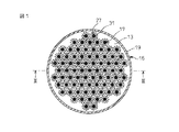
最初に、図1〜図4を参照して、本発明の熱交換器の第1の実施形態の構成について説明する。第1の実施形態の熱交換器は、いわゆるシェルアンドチューブタイプの蓄冷熱交換器11であり、蓄冷材13で充満されたハウジング15と、ハウジング15内を互いに平行に延び且つ内部を冷媒が流れる複数の冷媒チューブ17とを備える。ハウジング15は、詳細には、円筒状の胴部材であるシェル19と、シェル19の上下の開口端部に取り付けられる上側蓋板21及び下側蓋板23とによって構成されており、各部材はアルミニウム等の金属から形成されている。また、上側蓋板21には、ハウジング15内に蓄冷材13を封入するための注入口21bが形成されており、この注入口21bは蓄冷材13の注入完了後にプラグ25によって密封される。
Initially, with reference to FIGS. 1-4, the structure of 1st Embodiment of the heat exchanger of this invention is demonstrated. The heat exchanger according to the first embodiment is a so-called shell-and-tube type
蓄冷材13は、融点が低く、過冷却の発生しない物性を有するものが好ましく、例えばパラフィン等が蓄冷材13として使用され得る。また、冷媒としては、1,1,1,2−テトラフルオロエタン(HFC134a)などが使用される。
The
冷媒チューブ17の外周には、伝熱面を拡大して冷媒チューブ17内を流れる冷媒とハウジング15内の蓄冷材13との間の熱交換を効率良く行うために、複数の伝熱フィン27が設けられている。図1から図4に示されている実施形態では、12枚の伝熱フィン27が、冷媒チューブ17の外周に周方向に等間隔で設けられ、冷媒チューブ17の長手軸線29と垂直な断面において冷媒チューブ17の外周面から放射状に且つ冷媒チューブ17の長手軸線29(図4)の方向に冷媒チューブ17のほぼ全長にわたって延びている。また、各伝熱フィン27は、冷媒チューブ17の長手軸線29と垂直な方向に冷媒チューブ17の外周から同じ長さ分だけ突出しており、長手軸線29と垂直な方向の先端が同一の円上に位置するようになっている。
A plurality of
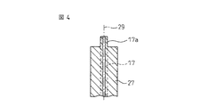
一方で、図4に示されているように、冷媒チューブ17は、その両端部に、伝熱フィン27が設けられていない円筒部17aを有しており、この円筒部17aを上側蓋板21及び下側蓋板23に形成された挿入穴21a、23aに挿入できるようになっている。冷媒チューブ17は、円筒部17aを挿入穴21a,23aに挿入した後、ろう付け等を行って上側蓋板21及び下側蓋板23に密封固定される。
On the other hand, as shown in FIG. 4, the
さらに、伝熱フィン27には、長手軸線29と垂直な方向における先端にそって、該先端から側方に突出するガイドリブ31が設けられている。詳細には、図2に示されているように、ガイドリブ31は伝熱フィン27の先端両側の伝熱面から、それぞれ、その伝熱面と垂直な方向に延びている。しかしながら、ガイドリブ31は伝熱フィン27の先端の一方側の伝熱面からのみ延びていてもよい。それぞれの冷媒チューブ17における隣接するガイドリブ31同士の周方向の隙間又はガイドリブ31と隣接する伝熱フィン27との周方向隙間は、他の冷媒チューブ17のガイドリブ31が通過できないような大きさに設計されている。
Further, the
これらガイドリブ31は、複数の冷媒チューブ17を束ねるなどして冷媒チューブ17同士を接近させたときに、隣接する二つの冷媒チューブ17のガイドリブ31がそれぞれの冷媒チューブ17の外周面からほぼ同じ距離だけ離れた位置で当接して、冷媒チューブ17同士がそれ以上近づくことを妨げるように機能する。
These
すなわち、隣接する二つの冷媒チューブ17は、ガイドリブ31の存在により、冷媒チューブ17の外周から伝熱フィン27の先端までの距離のほぼ2倍の間隔をあけて配置される。さらに、あたかも冷媒チューブ17の中心から伝熱フィン27までの距離を半径とした円形断面のチューブを束ねたかのように、互いに隣接する三つの冷媒チューブ17が、冷媒チューブ17の中心から伝熱フィン27までの距離の2倍の長さの辺を一辺とした正三角形のほぼ頂点位置に位置決めされる。後者の効果は、一つの冷媒チューブ17の外周の周方向に配置される伝熱フィン27の数を増加させ、ガイドリブ31がなす輪郭が円形に近づくほど高まる。もちろん、ガイドリブ31を円弧状に形成しても同様の効果を得ることができる。
That is, the two
冷媒チューブ17、伝熱フィン27、ガイドリブ31は、高い熱伝導率を有した金属、例えば、アルミニウム等から形成される。また、上述した冷媒チューブ17、伝熱フィン27及びガイドリブ31は、冷媒チューブ17の長手軸線29と垂直な断面が長手軸線29の方向に均一となるように延びているので、押出し加工により一体的に製造することができ、製造が容易であるという利点を有している。しかしながら、先端にガイドリブ31を備えた伝熱フィン27を冷媒チューブ17と別個に作成した後、伝熱フィンを27冷媒チューブ17の周囲に巻き付けてロウ付けや溶接等により接合するなど、他の方法により製造することも可能である。
The
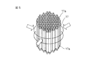
次に、図5から図7を参照して、図1から図4に示されている蓄冷熱交換器11の組立て手順について説明する。なお、図5においては、理解を容易にするために、伝熱フィン27及びガイドリブ31を備えた冷媒チューブ17を単なる円筒状に簡略して示している。
Next, with reference to FIGS. 5 to 7, an assembly procedure of the cold
先ず、図5に示されているように、押し出し加工等により製造された所定数の冷媒チューブ17を束ね外周方向から外力を作用させる。すると、ガイドリブ31の存在のために、各冷媒チューブ17のガイドリブ31が他の冷媒チューブ17のガイドリブ31と当接すると共に、冷媒チューブ17の周方向に隣り合う伝熱フィン27の間に他の冷媒チューブ17の伝熱フィン27が入り込むことを防止し、結果として、図2に示されるように、互いに隣接する三つの冷媒チューブ17が冷媒チューブ17の中心から伝熱フィン27の先端までの距離の2倍の長さの辺を一辺とする正三角形のほぼ頂点の位置に配置されるように、複数の冷媒チューブ17が互いに対して所定の位置に位置決めされる。
First, as shown in FIG. 5, a predetermined number of
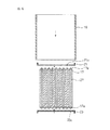
次に、互いに対して所定の相対位置に位置決めされた冷媒チューブ17の束をシェル19内に挿入し、冷媒チューブ17の束の上端及び下端にそれぞれ上側蓋板21及び下側蓋板23を取り付け、図3に示されるような蓄冷熱交換器11に組立てる。このとき、上側蓋板21及び下側蓋板23と伝熱フィン27の長手軸線方向端部との間には隙間が形成されるようにする。そして、ろう付け等により、シェル19、上側蓋板21、下側蓋板23及び冷媒チューブ17を接合する。
Next, the bundle of the
ここで、上側蓋板21及び下側蓋板23には、冷媒チューブ17の数と等しい数の挿入穴21a,23aが設けられており、各挿入穴21a,23aは、隣接する三つの挿入穴21a,23aが冷媒チューブ17の中心から伝熱フィン27の先端までの距離の2倍の長さの辺を一辺とする正三角形の頂点の位置に配置されるように形成されている。したがって、隣接する三つの冷媒チューブ17が冷媒チューブ17の中心から伝熱フィン27の先端までの距離の2倍の長さの辺を一辺とする正三角形のほぼ頂点の位置に位置決めされている冷媒チューブ17の束の上端及び下端を上側蓋板21及び下側蓋板23の挿入穴21a,23aに同時に挿入して冷媒チューブ17の束に上側蓋板21及び下側蓋板23を取り付けるのは容易である。
Here, the
このように、本発明に従って冷媒チューブ17の伝熱フィン27にガイドリブ31を設ければ、冷媒チューブ17を束ねることにより複数の冷媒チューブ17を互いから所定距離を隔てた所定の位置に容易に位置決めすることができ、冷媒チューブを束ねた状態で取り扱い、蓄冷熱交換器11の組立てを行うことが可能となる。したがって、蓄冷熱交換器11の組立てが容易になり、その生産性を向上させることが可能になる。
As described above, if the
このようにして組立てられた蓄冷熱交換器11には、注入口21bから蓄冷材13が注入される。このとき、注入された蓄冷材13は上側蓋板21及び下側蓋板23と冷媒チューブ17の伝熱フィン27の長手軸線方向端部との間の隙間から冷媒チューブ17の隣接する伝熱フィン27の間の空間に充満する。また、冷媒チューブ17における隣接する二つのガイドリブ31の周方向の隙間又はガイドリブ31の先端と隣接する伝熱フィン27との周方向の隙間が、隣接する二つの伝熱フィン27の間の空間にハウジング15内の蓄冷材13が進入することを助ける。
The
図7及び図8は、本発明の熱交換器の第2の実施形態を示している。第2の実施形態の熱交換器は、伝熱フィンの数及びガイドリブの配置を除いて、第1の実施形態の熱交換器と同様の構成を有している。すなわち、蓄冷熱交換器11′は、蓄冷材13で充満されたハウジング15と、ハウジング15内を互いに平行に延び且つ内部を冷媒が流れる複数の冷媒チューブ17とを備え、冷媒チューブ17の外周には、冷媒チューブ17の長手軸線29と垂直な断面において冷媒チューブ17の外周面から放射状に且つ冷媒チューブ17の長手軸線29の方向に冷媒チューブ17のほぼ全長にわたって延びる複数の伝熱フィン27が設けられている。
7 and 8 show a second embodiment of the heat exchanger of the present invention. The heat exchanger of the second embodiment has the same configuration as the heat exchanger of the first embodiment, except for the number of heat transfer fins and the arrangement of guide ribs. That is, the
しかしながら、本実施形態では、6枚の伝熱フィン27′が冷媒チューブ17の外周に周方向に等間隔(60°間隔)で設けられている点において、第1の実施形態と異なっている。さらに、第2の実施形態は、伝熱フィン27′の先端の伝熱面の両側からそれぞれ延びるガイドリブ31′が隣接する伝熱フィン27′の先端に向かって延びている点において、第1の実施形態と異なっている。すなわち、第2の実施形態のガイドリブ31′は、冷媒チューブ17の長手軸線29に垂直な断面において伝熱フィン27′の先端を頂点とした仮想上の正六角形の各辺に沿って延びている。他の部分については、第1の実施形態と同じであるので、ここでは詳しく説明しない。
However, this embodiment is different from the first embodiment in that six
第2の実施形態における冷媒チューブ17も第1の実施形態における冷媒チューブ17と同様に、冷媒チューブ17を束ねて外周方向から外力を作用させると、各冷媒チューブ17は、図8に示されているように、ガイドリブ31′の存在により、ガイドリブ31′同士を密着させた状態で、隣接する他の冷媒チューブ17と所定の距離を隔てて配置される。すなわち、冷媒チューブ17は、断面六角形の鉛筆を束ねたときの芯のように配置され、隣接する三つの冷媒チューブ17は、正三角形の各頂点の位置に配置されるようになる。
Similarly to the
ただし、このときの冷媒チューブ17の間の距離は、冷媒チューブ17の外周から伝熱フィン27の先端までの距離の2倍よりも小さくなる。したがって、第2の実施形態における冷媒チューブ17は第1の実施形態における冷媒チューブ17よりも密度の高い配置を可能とさせる利点を有する。
However, the distance between the
なお、この実施形態における伝熱フィン27′並びにガイドリブ31′も冷媒チューブ17の長手軸線29と垂直な断面が長手軸線29の方向に均一であることから、第1の実施形態の場合と同様に、冷媒チューブ17、伝熱フィン27′及びガイドリブ31′を押し出し加工により一体的に製造でき、その製造が容易である。
Note that the
第1の実施形態及び第2の実施形態では、伝熱フィン27、27′が冷媒チューブ17の長手軸線29の方向に延びているが、伝熱フィンは、冷媒チューブ17の長手軸線29の方向に間隔をあけて配置されている環状の伝熱フィンであってもよい(図示せず)。この場合、ガイドリブは、伝熱フィンの先端から、伝熱フィンの伝熱面と垂直方向、すなわち冷媒チューブ17の長手軸線29の方向に延びることになる。このため、伝熱フィン及びガイドリブを冷媒チューブと共に押し出し加工により製造することはできない。よって、例えば、環状の伝熱フィンと冷媒チューブ17とを鋳造や鍛造等により一体的に形成した後、環状の伝熱フィンの外周部を冷媒チューブ17の長手軸線29の方向に折り曲げることにより、または、伝熱フィンの外周に冷媒チューブ17の長手軸線29の方向に延びるガイドリブを溶接やろう付け等により接合することにより、冷媒チューブ17、伝熱フィン及びガイドリブを作成する必要がある。
In the first embodiment and the second embodiment, the
また、第1の実施形態及び第2の実施形態では、冷媒チューブ17の外周に複数の伝熱フィン27、27′が設けられている例が示されているが、本発明は複数の伝熱フィン27、27′に限定されるものではない。例えば、冷媒チューブ17の外周に螺旋状の伝熱フィンを設け、冷媒チューブ17の長手軸線29と垂直な方向における伝熱フィンの先端から該長手軸線29と平行に延びるガイドリブを設けてもよい。この場合、例えば、ガイドリブ付きの帯状伝熱フィンを押し出し加工等により作成した後、帯状伝熱フィンを冷媒チューブ17に螺旋状に巻き付けることにより、または、鋳造や鍛造等により螺旋状伝熱フィンと冷媒チューブ17とを一体的に形成した後、伝熱フィンの先端を折り曲げてガイドリブとすることにより、冷媒チューブ17、伝熱フィン及びガイドリブを作成すればよい。
In the first embodiment and the second embodiment, an example in which a plurality of
このような伝熱フィン及びガイドリブを有した冷媒チューブ17を用いても、第1の実施形態や第2の実施形態の場合と同様の効果を奏することができる。
Even if the
図9は、本発明の蓄冷熱交換器を用いた空調装置の一例である車両用空調装置33における冷凍サイクルの回路図を示している。車両用空調装置33は、冷媒を圧縮する圧縮機35と、圧縮機35から吐出された高圧冷媒の放熱を行う凝縮器37と、凝縮器37を通過した冷媒を減圧させる膨張弁39と、膨張弁39により減圧された低圧冷媒により冷却される蓄冷材13を有した第1の実施形態の蓄冷熱交換器11と、蓄冷熱交換器11を通過した液相冷媒を貯留する貯留タンク41と、冷媒の逆流を防止するための第1の逆止弁43と、液相冷媒を蒸発させることにより車室内空気を冷却する蒸発器45とを備え、この順番で各要素を管路で接続して冷却サイクルを構成している。
FIG. 9 shows a circuit diagram of a refrigeration cycle in the vehicle air conditioner 33 which is an example of an air conditioner using the cold storage heat exchanger of the present invention. The vehicle air conditioner 33 includes a
さらに、貯留タンク41と蒸発器45との間にある第1の逆止弁43と並列に循環ポンプ47が配置されていると共に、第2の逆止弁49を備えた枝管路51を介して蒸発器43と圧縮機35との間の管路を膨張弁39と蓄冷熱交換器11との間の管路と連通させている。
Further, a
圧縮機35はエンジン(図示せず)の動力を用いて駆動され、冷媒を上流側から吸入して圧縮し下流側に吐出する。通常の冷房モードすなわち蓄冷モードでは、圧縮機35により圧縮された高温高圧の過熱気相冷媒が凝縮器37により冷却され、過冷却状態の高圧液相冷媒となって膨張弁39に流入する。冷媒は、膨張弁39により減圧され、低圧の気液2相状態となり、蓄冷熱交換器11に流入する。なお、このとき、膨張弁39から出た冷媒の圧力により第2の逆止弁49は閉弁し、冷媒が枝管路51を通って圧縮機35の上流側に流れることはない。
The
蓄冷熱交換器11に流入した冷媒は、冷媒チューブ17内を通過する際にハウジング15内に封入された蓄冷材13を冷却させ、蓄冷する。蓄冷熱交換器11を通過して蓄冷材13に吸熱された冷媒は液相冷媒となって貯留タンク45内に貯留される。その後、貯留タンク45の冷媒の圧力により液相冷媒は貯留タンク45と第1の逆止弁43とを接続する管路を通って蒸発器45に至る。なお、貯留タンク45の冷媒圧力により第1の逆止弁43には下流側(蒸発器45側)に向かって圧力が作用し、開弁した状態となるので、液相冷媒の通過を許容することができる。また、循環ポンプ47は作動していないので、循環ポンプ47を介して蒸発器45に流入する冷媒や第1の逆止弁43を通った後循環ポンプ47を通って貯留タンク41に戻る冷媒はほとんどない。
The refrigerant that has flowed into the cold
蒸発器45に流入した低圧液相冷媒は、蒸発器45に送り込まれる車室内の空気から吸熱して蒸発し、気相冷媒となる。このとき冷却された空気が車室内に吹き出して車室の冷房を行う。一方、蒸発器45から送り出された気相冷媒は、再び圧縮機35の入口に送り込まれ、圧縮される。
The low-pressure liquid-phase refrigerant that has flowed into the
次に、エンジンが停止したときの放熱モードでの動作を説明する。
エンジンが停止して圧縮機35の作動が停止すると、制御装置(図示せず)が循環ポンプ47を作動させる。すると、貯留タンク41内に貯留された液相冷媒が循環ポンプ47により吸引され、蒸発器45の上流側に吐出される。これにより第1の逆止弁43には蒸発器45側から貯留タンク41側へ冷媒圧力が作用して第1の逆止弁43は閉弁するので、冷媒は蒸発器45へ導入されることになる。そして、蒸発器45に導入された液相冷媒は車室内空気から吸熱して蒸発し、気相冷媒となる。このとき、車室内空気が冷却されるので、エンジンが停止しても継続して車室内空気の冷房が行われる。
Next, the operation in the heat dissipation mode when the engine is stopped will be described.
When the engine is stopped and the operation of the
一方、圧縮機35は停止しているので、蒸発器45を出た気相冷媒は、第2の逆止弁49を備えた枝管路51を通って蓄冷熱交換器11に供給される。このとき、冷媒の圧力により第2の逆止弁49は開弁し、冷媒の通過を許容する。そして、蓄冷熱交換器11では、冷媒が冷媒チューブ17を通る際に蓄冷材13により冷却され、液相に変化し、貯留タンク41内に貯留される。このようにして、貯留タンク41内に液相冷媒が残存している限り、車室内冷房を継続することが可能となる。
On the other hand, since the
上記の空調装置33は一例であり、本発明の蓄熱熱交換器11は、他の構成の空調装置においても使用され得ることはいうまでもない。
The air conditioner 33 is an example, and it is needless to say that the heat
11…蓄冷熱交換器
13…蓄冷材
15…ハウジング
17…冷媒チューブ
27、27′…伝熱フィン
29…長手軸線
31、31′…ガイドリブ
33…空調装置
DESCRIPTION OF
Claims (8)
前記冷媒チューブの長手軸線と垂直な方向における前記伝熱フィンの先端から側方に突出するガイドリブが前記伝熱フィンの先端に沿って設けられていることを特徴とする熱交換器。 A housing filled with fluid, a plurality of refrigerant tubes that extend parallel to each other in the housing and through which the refrigerant flows, and heat transfer fins provided on the outer periphery of each refrigerant tube to expand the heat transfer surface, A heat exchanger for exchanging heat between the refrigerant flowing in the refrigerant tube and the fluid in the housing,
A heat exchanger characterized in that a guide rib protruding laterally from the tip of the heat transfer fin in a direction perpendicular to the longitudinal axis of the refrigerant tube is provided along the tip of the heat transfer fin.
Priority Applications (1)
| Application Number | Priority Date | Filing Date | Title |
|---|---|---|---|
| JP2004113204A JP2005299956A (en) | 2004-04-07 | 2004-04-07 | Heat exchanger |
Applications Claiming Priority (1)
| Application Number | Priority Date | Filing Date | Title |
|---|---|---|---|
| JP2004113204A JP2005299956A (en) | 2004-04-07 | 2004-04-07 | Heat exchanger |
Publications (1)
| Publication Number | Publication Date |
|---|---|
| JP2005299956A true JP2005299956A (en) | 2005-10-27 |
Family
ID=35331705
Family Applications (1)
| Application Number | Title | Priority Date | Filing Date |
|---|---|---|---|
| JP2004113204A Pending JP2005299956A (en) | 2004-04-07 | 2004-04-07 | Heat exchanger |
Country Status (1)
| Country | Link |
|---|---|
| JP (1) | JP2005299956A (en) |
Cited By (4)
| Publication number | Priority date | Publication date | Assignee | Title |
|---|---|---|---|---|
| WO2010017897A3 (en) * | 2008-08-11 | 2010-06-10 | Compact Dynamics Gmbh | Motor vehicle having a motor vehicle heat exchanger |
| RU2596685C2 (en) * | 2014-08-01 | 2016-09-10 | Общество с ограниченной ответственностью "Научно-производственный комплекс "ГАРАНТ" (ООО "НПК ГАРАНТ") | Heat exchange module |
| WO2022209359A1 (en) * | 2021-04-01 | 2022-10-06 | 三菱重工業株式会社 | Cooling system |
| CN119334171A (en) * | 2024-12-20 | 2025-01-21 | 平潭煜想时代科技有限公司 | A heat exchanger and a mold and method for preparing the heat exchanger |
-
2004
- 2004-04-07 JP JP2004113204A patent/JP2005299956A/en active Pending
Cited By (6)
| Publication number | Priority date | Publication date | Assignee | Title |
|---|---|---|---|---|
| WO2010017897A3 (en) * | 2008-08-11 | 2010-06-10 | Compact Dynamics Gmbh | Motor vehicle having a motor vehicle heat exchanger |
| RU2596685C2 (en) * | 2014-08-01 | 2016-09-10 | Общество с ограниченной ответственностью "Научно-производственный комплекс "ГАРАНТ" (ООО "НПК ГАРАНТ") | Heat exchange module |
| WO2022209359A1 (en) * | 2021-04-01 | 2022-10-06 | 三菱重工業株式会社 | Cooling system |
| JP2022158103A (en) * | 2021-04-01 | 2022-10-17 | 三菱重工業株式会社 | cooling system |
| US12501581B2 (en) | 2021-04-01 | 2025-12-16 | Mitsubishi Heavy Industries, Ltd. | Cooling system |
| CN119334171A (en) * | 2024-12-20 | 2025-01-21 | 平潭煜想时代科技有限公司 | A heat exchanger and a mold and method for preparing the heat exchanger |
Similar Documents
| Publication | Publication Date | Title |
|---|---|---|
| US9511458B2 (en) | Heat exchanger with thermal storage function and method of manufacturing the same | |
| JP5202030B2 (en) | Double tube heat exchanger | |
| US9109821B2 (en) | Condenser for vehicle | |
| US11059345B2 (en) | Storage evaporator having phase change material for use in vehicle air conditioning system | |
| JP6180281B2 (en) | Heat exchanger with heat storage function and manufacturing method thereof | |
| JP5768480B2 (en) | Cold storage heat exchanger | |
| JP5274175B2 (en) | Cold storage heat exchanger | |
| JP2015087086A5 (en) | ||
| JP2014224670A (en) | Double-pipe heat exchanger | |
| JP2009162396A (en) | Double-wall-tube heat exchanger | |
| JP2007032949A (en) | Heat exchanger | |
| KR101756213B1 (en) | Cold reserving heat exchanger | |
| JP4179092B2 (en) | Heat exchanger | |
| JP2001021234A (en) | Cooler | |
| JP2011191034A (en) | Dual-pipe heat exchanger | |
| JP2009041798A (en) | Heat exchanger | |
| JP2005299956A (en) | Heat exchanger | |
| JP5898892B2 (en) | Intermediate heat exchanger | |
| JP5202029B2 (en) | Double tube heat exchanger | |
| JP6573030B2 (en) | Cold storage heat exchanger | |
| JP2004183960A (en) | Heat exchanger | |
| JP2015017762A (en) | Double tube heat exchanger | |
| KR20160125033A (en) | Heat exchanger for refrigerator vehicle and manufacturing thereof | |
| JP2014095482A (en) | Double-pipe heat exchanger | |
| JP7151560B2 (en) | cold storage heat exchanger |