JP2005299939A - Waste combustion method in stoker furnace, and stoker furnace - Google Patents
Waste combustion method in stoker furnace, and stoker furnace Download PDFInfo
- Publication number
- JP2005299939A JP2005299939A JP2004112131A JP2004112131A JP2005299939A JP 2005299939 A JP2005299939 A JP 2005299939A JP 2004112131 A JP2004112131 A JP 2004112131A JP 2004112131 A JP2004112131 A JP 2004112131A JP 2005299939 A JP2005299939 A JP 2005299939A
- Authority
- JP
- Japan
- Prior art keywords
- combustion chamber
- air
- stoker
- secondary air
- waste
- Prior art date
- Legal status (The legal status is an assumption and is not a legal conclusion. Google has not performed a legal analysis and makes no representation as to the accuracy of the status listed.)
- Withdrawn
Links
- 239000002699 waste material Substances 0.000 title claims abstract description 54
- 238000009841 combustion method Methods 0.000 title claims abstract description 10
- 238000002485 combustion reaction Methods 0.000 claims abstract description 127
- 230000003647 oxidation Effects 0.000 claims abstract description 24
- 238000007254 oxidation reaction Methods 0.000 claims abstract description 24
- 239000007789 gas Substances 0.000 claims description 46
- QVGXLLKOCUKJST-UHFFFAOYSA-N atomic oxygen Chemical compound [O] QVGXLLKOCUKJST-UHFFFAOYSA-N 0.000 claims description 29
- 239000001301 oxygen Substances 0.000 claims description 29
- 229910052760 oxygen Inorganic materials 0.000 claims description 29
- 238000011144 upstream manufacturing Methods 0.000 claims description 24
- 230000009931 harmful effect Effects 0.000 abstract description 10
- 239000000126 substance Substances 0.000 abstract description 6
- 238000005979 thermal decomposition reaction Methods 0.000 abstract description 4
- HGUFODBRKLSHSI-UHFFFAOYSA-N 2,3,7,8-tetrachloro-dibenzo-p-dioxin Chemical compound O1C2=CC(Cl)=C(Cl)C=C2OC2=C1C=C(Cl)C(Cl)=C2 HGUFODBRKLSHSI-UHFFFAOYSA-N 0.000 abstract 1
- 239000010410 layer Substances 0.000 description 34
- 239000000428 dust Substances 0.000 description 19
- 150000002013 dioxins Chemical class 0.000 description 9
- 230000000694 effects Effects 0.000 description 6
- 229910001385 heavy metal Inorganic materials 0.000 description 6
- 239000010813 municipal solid waste Substances 0.000 description 6
- 238000002844 melting Methods 0.000 description 5
- 230000008018 melting Effects 0.000 description 5
- IJGRMHOSHXDMSA-UHFFFAOYSA-N Atomic nitrogen Chemical compound N#N IJGRMHOSHXDMSA-UHFFFAOYSA-N 0.000 description 4
- 238000001035 drying Methods 0.000 description 4
- 238000002309 gasification Methods 0.000 description 4
- 238000002156 mixing Methods 0.000 description 4
- 238000000197 pyrolysis Methods 0.000 description 4
- 238000003756 stirring Methods 0.000 description 4
- 239000002344 surface layer Substances 0.000 description 4
- XLYOFNOQVPJJNP-UHFFFAOYSA-N water Chemical compound O XLYOFNOQVPJJNP-UHFFFAOYSA-N 0.000 description 4
- 230000003247 decreasing effect Effects 0.000 description 3
- 238000005516 engineering process Methods 0.000 description 3
- 206010021143 Hypoxia Diseases 0.000 description 2
- 238000007664 blowing Methods 0.000 description 2
- 238000006243 chemical reaction Methods 0.000 description 2
- 230000007423 decrease Effects 0.000 description 2
- 239000000446 fuel Substances 0.000 description 2
- 238000000034 method Methods 0.000 description 2
- 229910052757 nitrogen Inorganic materials 0.000 description 2
- 229910017464 nitrogen compound Inorganic materials 0.000 description 2
- 150000002830 nitrogen compounds Chemical class 0.000 description 2
- OKTJSMMVPCPJKN-UHFFFAOYSA-N Carbon Chemical compound [C] OKTJSMMVPCPJKN-UHFFFAOYSA-N 0.000 description 1
- UGFAIRIUMAVXCW-UHFFFAOYSA-N Carbon monoxide Chemical compound [O+]#[C-] UGFAIRIUMAVXCW-UHFFFAOYSA-N 0.000 description 1
- 229910052799 carbon Inorganic materials 0.000 description 1
- 150000001875 compounds Chemical class 0.000 description 1
- 238000007796 conventional method Methods 0.000 description 1
- 238000001816 cooling Methods 0.000 description 1
- 238000010828 elution Methods 0.000 description 1
- 238000000605 extraction Methods 0.000 description 1
- 239000003546 flue gas Substances 0.000 description 1
- 238000010438 heat treatment Methods 0.000 description 1
- 239000002440 industrial waste Substances 0.000 description 1
- 238000004519 manufacturing process Methods 0.000 description 1
- 239000000463 material Substances 0.000 description 1
- 239000000155 melt Substances 0.000 description 1
- 239000000203 mixture Substances 0.000 description 1
- 238000005192 partition Methods 0.000 description 1
- 230000002250 progressing effect Effects 0.000 description 1
- 239000011269 tar Substances 0.000 description 1
Images


Landscapes
- Incineration Of Waste (AREA)
- Vertical, Hearth, Or Arc Furnaces (AREA)
- Furnace Details (AREA)
Abstract
Description
本発明は、ストーカ上に載置された廃棄物を移送しながらストーカ下部より一次空気を導入して燃焼処理するとともに、燃焼により発生した未燃ガスを二次空気の導入により二次燃焼させる構成としたストーカ炉における廃棄物燃焼方法及び該ストーカ炉に関し、特にNOX等の有害物質の発生を抑制可能としたストーカ炉における廃棄物燃焼方法及び該ストーカ炉に関する。 The present invention is a structure in which primary air is introduced from the lower part of the stalker while burning the waste placed on the stalker, and the unburned gas generated by the combustion is subjected to secondary combustion by introducing secondary air. and it was relates waste combustion method and the stoker in stoker, in particular to waste combustion method and the stoker in stoker which enables suppressing the generation of harmful substances such as NO X.
従来より、一般廃棄物、産業廃棄物等を焼却処理する際に、運転の安定性、経済性の面で優れたストーカ炉が広く用いられている。一般にストーカ炉は、ストーカ上に投入された廃棄物を移送しながら炉底より一次空気を導入し、前記ストーカ上に形成された一次燃焼室にて廃棄物の乾燥、熱分解を行なった後、ストーカ下流側にて後燃焼を行なう構成となっている。また、一次燃焼室にて発生した排ガス中に含まれる未燃分は、該一次燃焼室の上方に位置する二次燃焼室にて二次空気の導入により二次燃焼される。
このようなストーカ炉では、廃棄物の燃焼に伴い排ガス中に生成されるNOX、ダイオキシン類等の有害物質、焼却残渣に含まれる重金属類等の有害物質の処理が問題となっている。
Conventionally, when incinerating general waste, industrial waste, etc., a stoker furnace excellent in terms of operation stability and economy has been widely used. In general, a stoker furnace introduces primary air from the bottom of the furnace while transferring the waste charged on the stoker, and after drying and pyrolyzing the waste in the primary combustion chamber formed on the stoker, The post-combustion is performed on the downstream side of the stalker. Further, the unburned component contained in the exhaust gas generated in the primary combustion chamber is subjected to secondary combustion in the secondary combustion chamber located above the primary combustion chamber by introducing secondary air.
In such a stoker furnace, processing of harmful substances such as NO x and dioxins generated in the exhaust gas upon combustion of waste and heavy metals contained in incineration residue is a problem.
一般にNOXの発生は、廃棄物中の窒素分が燃焼過程でNH3等の中間窒素化合物を生成し、この中間窒素化合物がNOXに転化する反応が主であり、NOXの発生量は燃焼条件に深く関与し、炉内温度および空気過剰率の低下とともに減少することが判っている。
そこで、特許文献1(特開2003−329228号公報)では、NOXの発生を抑制するために、炉底より導入する一次空気を酸素富化空気とし、該一次空気の酸素濃度が廃棄物の進行方向に行くに従って低下するように構成している。これにより多くの酸素を必要とする廃棄物の燃焼初期においては酸素濃度の高い一次空気を供給し、燃焼終了近くで高温となっている部分では酸素濃度の低い一次空気を供給して、NOXの発生を抑制するとともに安定な燃焼を実現している。
Generation of general NO X, the nitrogen content in the waste to produce an intermediate nitrogen compounds such as NH 3 in the combustion process, the intermediate nitrogen compounds is the main reaction of converting the NO X, the generation amount of the NO X is It has been found that it is deeply involved in combustion conditions and decreases with decreasing furnace temperature and excess air ratio.
Therefore, Patent Document 1 (JP 2003-329228), in order to suppress the generation of NO X, the primary air introduced from the bottom of the furnace and oxygen-enriched air, the oxygen concentration of the primary air is waste It is configured to decrease as it goes in the direction of travel. Thereby supplying high oxygen concentration primary air in initial combustion of waste requires more oxygen, and supplies the primary air of low oxygen concentration at a portion which is a high temperature near the ends combustion, NO X Stable combustion is achieved while suppressing the generation of CO2.
しかし、特許文献1によれば廃棄物の進行方向下流側では酸素濃度の低い一次空気を導入しているためNOXの発生は殆どないが、上流側では酸素濃度が高い一次空気を導入しているため、NOXの発生は避けられない。
また、特許文献2(特開2001−263631号公報)では、ストーカ下部から導入する一次空気の供給量を一次空気比で1.2以下、好適には0.9〜1.1とするとともに、ストーカ下流側の燃焼排ガスを炉外へ引き抜き一次燃焼室を還元性雰囲気とし、この引き抜いた燃焼排ガスを二次燃焼室に吹き込み、さらにその上方に二次空気を導入する構成とし、未燃ガスや未燃物を三段燃焼させている。これによりNOX、ダイオキシン類等の有害成分を低減することが可能である。
However, according to Patent Document 1, primary air having a low oxygen concentration is introduced on the downstream side in the waste traveling direction, so that NO X is hardly generated. On the upstream side, primary air having a high oxygen concentration is introduced. Therefore, generation of NO X is inevitable.
Moreover, in patent document 2 (Unexamined-Japanese-Patent No. 2001-266331), the supply amount of the primary air introduce | transduced from a stoker lower part shall be 1.2 or less by a primary air ratio, Preferably it is 0.9-1.1, and combustion exhaust gas of the stoker downstream side The primary combustion chamber is pulled out of the furnace to a reducing atmosphere, the exhausted flue gas is blown into the secondary combustion chamber, and the secondary air is further introduced above it. It is burning. Thereby, harmful components such as NO x and dioxins can be reduced.
また、近年ではこれらのストーカ炉を改良し、低公害型でかつ排ガス量の大幅低減を可能とし、さらには重金属類の溶出性を低減できるストーカ炉が特許文献3(特開2003−166705号公報)等にて提案されている。
図4に示すようにかかるストーカ炉50では、廃棄物投入ホッパ51よりストーカ52上に投入された廃棄物を、上流側ストーカの下部から加熱一次空気60を空気過剰率1以下で吹き込みながら乾燥、熱分解、燃焼ガス化させるとともに、下流側ストーカの下部から常温または高温酸素富化空気61を吹き込んで、前記上流側ストーカで生成した焼却残渣を未燃炭素分の燃焼熱にて焙焼及び/または溶融を行なう構成としている。また、燃焼により発生した排ガスは、二次燃焼室55にて噴出ノズル56から二次空気を導入しながら二次燃焼する。
In recent years, a stoker furnace that improves these stoker furnaces, is a low-pollution type, can significantly reduce the amount of exhaust gas, and can further reduce the elution of heavy metals has been disclosed in Japanese Patent Application Laid-Open No. 2003-166705. ) Etc.
In the stalker furnace 50 as shown in FIG. 4, the waste charged on the stalker 52 from the
前記ストーカ炉50が特許文献1及び特許文献2に記載したストーカ炉と異なる点は、前記ストーカ下部から導入する一次空気の空気過剰率を1.0以下とした構成にあり、これにより廃棄物を積極的にガス化している。
また、熱分解/燃焼する上流側と、焙焼/溶融する下流側とにストーカ52を分離した構成も相違しており、これにより焼却〜灰処理までの一貫した処理をストーカ炉内で行なうことができ、設備の小型化、処理時間の短縮化が達成できる。また、前記ストーカ炉50では、上流側一次空気の条件を一次空気温度120〜800℃、酸素濃度8〜30%、空気過剰率0.2〜1.0とし、下流側一次空気の条件を酸素濃度21〜30%としており、このように空気過剰率を従来より大幅に低減することで排ガスの発生量を大幅に低減し、さらに空気過剰率の低減による燃焼の不安定化を一次空気温度等の他の条件により解決することにより、安定した燃焼を可能とし、灰及び排ガス性状の向上を可能としている。
The difference between the stoker furnace 50 and the stoker furnace described in Patent Document 1 and Patent Document 2 is that the excess air ratio of the primary air introduced from the lower part of the stoker is set to 1.0 or less. It is gasified.
Moreover, the structure which isolate | separated the stoker 52 into the upstream side which carries out pyrolysis / combustion, and the downstream side which carries out roasting / melting is also different, and this performs the consistent process from incineration to ash treatment in a stoker furnace. The equipment can be downsized and the processing time can be shortened. In the stoker furnace 50, the upstream primary air conditions are primary air temperature 120 to 800 ° C., the oxygen concentration is 8 to 30%, the excess air ratio is 0.2 to 1.0, and the downstream primary air conditions are oxygen concentrations 21 to 30. In this way, the amount of exhaust gas generated is greatly reduced by significantly reducing the excess air ratio as compared to the conventional method, and the instability of combustion due to the reduction of the excess air ratio is reduced to other conditions such as the primary air temperature. By solving the above, stable combustion is possible, and ash and exhaust gas properties can be improved.
上記したように、前記特許文献1及び2では一次空気の空気過剰率が大きいため排ガス量が多く、排ガス処理設備が大型化するという問題点があった。また、特許文献2では、一次燃焼室を還元性雰囲気にしてNOXを低減する構成としているが、空気過剰率が大きいため完全な還元性雰囲気は得られず、NOXの生成は回避できなかった。
特許文献3のストーカ炉はこのような従来の問題点が改善され、飛躍的に進歩した技術であるが、かかる装置も酸素を吹き込み燃焼させなければならないため、NOX、ダイオキシン類等の生成は避けられない問題であった。
従って、本発明は上記従来技術をさらに発展させた技術として、排ガス量の低減を図り炉のコンパクト化を可能とするとともに、NOX、ダイオキシン類等の有害物質の生成を最小限に抑えることができるストーカ炉における廃棄物燃焼方法及び該ストーカ炉を提供することを目的とする。
As described above, Patent Documents 1 and 2 have a problem that the amount of exhaust gas is large because the excess air ratio of the primary air is large, and the exhaust gas treatment facility is enlarged. In Patent Document 2 has a configuration for reducing the NO X by the primary combustion chamber in a reducing atmosphere, complete reduction atmosphere due to the large excess air ratio can not be obtained, generation of the NO X is not be avoided It was.
The stoker furnace of Patent Document 3 is a technology that has improved such conventional problems and has made great progress. However, since such an apparatus must also be blown and burned with oxygen, the production of NO x , dioxins, etc. It was an inevitable problem.
Therefore, the present invention is a technology that further develops the above-described conventional technology, which makes it possible to reduce the amount of exhaust gas and make the furnace compact, and to minimize the generation of harmful substances such as NO x and dioxins. It is an object of the present invention to provide a waste burning method in a stoker furnace and the stoker furnace.
そこで、本発明はかかる課題を解決するために、
ストーカ上方に設けられた一次燃焼室にてストーカ下部より高温一次空気を空気過剰率約0.5以下で導入し、主として廃棄物の熱分解を行なうとともに、前記一次燃焼室の上方に設けられた二次燃焼室にて前記一次燃焼室から発生した未燃ガスを二次空気の導入により二次燃焼させるストーカ炉における廃棄物燃焼方法において、
前記二次燃焼室のうち廃棄物層の直上に二次空気を導入して還元域を形成し、該還元域で前記未燃ガスの燃焼を行なった後に、前記還元域の上方に前記二次空気より空気過剰率が大である二次空気を導入して酸化域を形成し、該酸化域で前記未燃ガスの再燃焼を行なうことを特徴とする。
Therefore, in order to solve this problem, the present invention provides:
In the primary combustion chamber provided above the stoker, high-temperature primary air is introduced from the lower part of the stoker at an excess air ratio of about 0.5 or less, mainly to thermally decompose waste, and to the secondary combustion chamber provided above the primary combustion chamber. In a waste combustion method in a stoker furnace in which unburned gas generated from the primary combustion chamber in the combustion chamber is subjected to secondary combustion by introducing secondary air,
In the secondary combustion chamber, secondary air is introduced directly above the waste layer to form a reduction zone, and after burning the unburned gas in the reduction zone, the secondary air is placed above the reduction zone. Secondary air having a larger excess air ratio than air is introduced to form an oxidation zone, and the unburned gas is reburned in the oxidation zone.
本発明によれば、二次燃焼室を還元域と酸化域とに分けることで2段燃焼による脱硝効果が得られ、炉内ガス中のNOXを低減することが可能となる。また、本発明では前記一次空気の空気過剰率を約0.5以下と極めて低い値に設定しているため、完全に近い還元状態を達成することができ、脱硝効率を大幅に向上させることができる。このとき、二次空気を複数箇所から導入する構成とすると良く、炉内ガスとの撹拌、混合が十分に行なわれ、2段燃焼の効果を十分に発揮することができる。
また、本発明において、前記還元域に導入する二次空気の空気過剰率を約0.1〜0.6の範囲内とし、前記酸化域に導入する二次空気の空気過剰率を約0.3〜0.7の範囲内で前記還元域に導入する二次空気の空気過剰率より大である値に設定することが好ましい。これにより、前記還元域及び前記酸化域が最適な状態で形成され、脱硝効率が向上する。
According to the present invention, by dividing the secondary combustion chamber into the reduction zone and the oxidation zone, a denitration effect by the two-stage combustion can be obtained, and NO X in the furnace gas can be reduced. In the present invention, since the excess air ratio of the primary air is set to a very low value of about 0.5 or less, a nearly completely reduced state can be achieved, and the denitration efficiency can be greatly improved. At this time, it is preferable that the secondary air is introduced from a plurality of locations, and stirring and mixing with the in-furnace gas are sufficiently performed, and the effect of the two-stage combustion can be sufficiently exhibited.
In the present invention, the excess air ratio of the secondary air introduced into the reduction zone is in the range of about 0.1 to 0.6, and the excess air ratio of the secondary air introduced into the oxidation zone is in the range of about 0.3 to 0.7. It is preferable to set a value that is greater than the excess air ratio of the secondary air introduced into the reduction zone. Thereby, the reduction zone and the oxidation zone are formed in an optimal state, and the denitration efficiency is improved.
さらに、前記一次燃焼室の上流側にて導入する高温一次空気が、温度約200〜400℃、酸素濃度約8〜21%、空気過剰率約0.1〜0.5となるように設定することを特徴とする。
従来炉における燃焼反応は、炉内の放射熱の作用により廃棄物層の表層から着火して下方に向けて反応が進んでいた。しかし、本発明のような高温一次空気の条件とすることにより廃棄物層の底部より着火して上方に向けて燃焼が進行する反応が主体となる。
かかる構成により、火炎面より上側の廃棄物層は火炎面からの高温、低酸素濃度のガスが供給されるため熱分解ガス化が促進される。さらに、火炎面が上方に向けて進行する際に、熱の浮力が利用されて従来炉で見られる火炎面の下側移動よりも燃焼速度が速い。さらにまた、これらの作用によりストーカ炉をコンパクト化することができる。
Further, the high temperature primary air introduced on the upstream side of the primary combustion chamber is set to have a temperature of about 200 to 400 ° C., an oxygen concentration of about 8 to 21%, and an excess air ratio of about 0.1 to 0.5. To do.
The combustion reaction in the conventional furnace is ignited from the surface layer of the waste layer by the action of radiant heat in the furnace and proceeds downward. However, by using the conditions of high temperature primary air as in the present invention, the reaction is ignited mainly from the bottom of the waste layer and the combustion proceeds upward.
With such a configuration, the waste layer above the flame surface is supplied with high temperature, low oxygen concentration gas from the flame surface, so that pyrolysis gasification is promoted. Furthermore, when the flame surface travels upward, the buoyancy of heat is used, and the combustion speed is faster than the downward movement of the flame surface seen in conventional furnaces. Furthermore, the stoker furnace can be made compact by these actions.
また、前記高温一次空気の温度条件で下限を200℃とすることにより、上記したように廃棄物層下部に着火することができ、上方に向けて進行する燃焼反応を主体とすることができる。また、上限を400℃とすることで、ストーカ炉の耐久性を向上させることができる。
また、前記高温一次空気の酸素濃度を21%以下とすることで、廃棄物層内の火炎面での緩慢燃焼を実現することができる。これにより、急激な燃焼によって生じる局所的酸素不足領域が減少するため、NOX、ダイオキシン類の発生抑制が達成できる。さらに、酸素濃度を8%以下に下げすぎないことで、火炎面温度を高く保ち廃棄物層内の鉛等の重金属類を気化させることができ、主灰の再利用が可能となる。
Further, by setting the lower limit to 200 ° C. under the temperature condition of the high temperature primary air, the lower part of the waste layer can be ignited as described above, and the combustion reaction progressing upward can be mainly used. Moreover, durability of a stoker furnace can be improved by making an upper limit into 400 degreeC.
Further, by setting the oxygen concentration of the high temperature primary air to 21% or less, it is possible to realize slow combustion on the flame surface in the waste layer. Thereby, the local oxygen deficiency region generated by the rapid combustion is decreased, NO X, suppressing generation of dioxins can be achieved. Furthermore, by not reducing the oxygen concentration too much to 8% or less, the flame surface temperature can be kept high, and heavy metals such as lead in the waste layer can be vaporized, and the main ash can be reused.
さらに、前記還元域に導入する二次空気を、前記一次燃焼室の上流側に位置する廃棄物層直上より導入することを特徴とする。このように、還元域における二次空気の吹き込みを一次燃焼室上流側に集中させることで、該上流側のみから発生する高濃度の未燃ガスを効果的に二次空気と混合させることができる。
またこれらの発明によれば、還元域で十分混合された炉内ガスが酸化域に送られてくるため、効果的にガス燃焼が行なわれ、未燃分の低減、NOX、ダイオキシン類等の有害成分の低減が達成できる。
Further, the secondary air introduced into the reduction zone is introduced from directly above the waste layer located upstream of the primary combustion chamber. Thus, by concentrating the blowing of secondary air in the reduction zone on the upstream side of the primary combustion chamber, it is possible to effectively mix the high-concentration unburned gas generated only from the upstream side with the secondary air. .
In addition, according to these inventions, the in-furnace gas sufficiently mixed in the reduction zone is sent to the oxidation zone, so that the gas combustion is performed effectively, reducing unburned matter, NO x , dioxins, etc. Reduction of harmful components can be achieved.
また、上記した発明を好適に実施する装置の発明として、
ストーカ上方に一次燃焼室が設けられ、該一次燃焼室ではストーカ下部より高温一次空気が空気比約0.5以下で導入され主として廃棄物の熱分解が行なわれ、前記一次燃焼室の上方には前記一次燃焼室から発生した未燃ガスを二次空気の導入により二次燃焼させる二次燃焼室が設けられたストーカ炉において、
前記二次燃焼室には、廃棄物層の直上に配設された二次空気導入口から二次空気が導入されて還元域が形成されるとともに、前記還元域の上方に配設された二次空気導入口から前記二次空気より空気過剰率が大である二次空気が導入されて酸化域が形成されることを特徴とする。
In addition, as an invention of a device that suitably implements the above-described invention,
A primary combustion chamber is provided above the stoker. In the primary combustion chamber, high-temperature primary air is introduced from the lower portion of the stoker at an air ratio of about 0.5 or less to mainly thermally decompose waste. Above the primary combustion chamber, the primary combustion chamber is located above the primary combustion chamber. In a stoker furnace provided with a secondary combustion chamber in which unburned gas generated from the combustion chamber is subjected to secondary combustion by introducing secondary air,
In the secondary combustion chamber, secondary air is introduced from a secondary air introduction port disposed directly above the waste layer to form a reduction zone, and a secondary zone disposed above the reduction zone is formed. The secondary air having an excess air ratio larger than that of the secondary air is introduced from the secondary air inlet to form an oxidation zone.
さらに、前記還元域に導入する二次空気の空気過剰率を約0.1〜0.6の範囲内とし、前記酸化域に導入する二次空気の空気過剰率を約0.3〜0.7の範囲内で前記還元域に導入する二次空気の空気過剰率より大である値に設定することが好適である。
さらにまた、前記一次燃焼室の上流側にて導入される高温一次空気が、温度約200〜400℃、酸素濃度約8〜21%、空気過剰率約0.1〜0.5となるように設定されていることが好ましい。
Further, the excess air ratio of the secondary air introduced into the reduction zone is within the range of about 0.1 to 0.6, and the excess air ratio of the secondary air introduced into the oxidation zone is within the range of about 0.3 to 0.7. It is preferable to set a value that is larger than the excess air ratio of the secondary air introduced into the.
Furthermore, the high temperature primary air introduced upstream of the primary combustion chamber is set to have a temperature of about 200 to 400 ° C., an oxygen concentration of about 8 to 21%, and an excess air ratio of about 0.1 to 0.5. It is preferable.
また、前記還元域の二次空気導入口が、前記一次燃焼室の上流側に位置する廃棄物層の直上に設けられていることを特徴とする。
また、前記還元域の二次空気導入口が前記廃棄物の移送方向に対して側面側の炉壁に複数設けられており、該二次空気導入口が前記廃棄物層にほぼ平行な直線状に複数列置されるとともに、対面する二次空気導入口が夫々交互に位置するように配設されることを特徴とする。このような構成とすることで、前記還元域にて二次空気がエアーカーテンを形成し、廃棄物層からのガスと二次空気とを効果的に混合することができる。
In addition, the secondary air inlet of the reduction zone is provided directly above the waste layer located upstream of the primary combustion chamber.
A plurality of secondary air inlets in the reduction zone are provided on the side of the furnace wall with respect to the waste transfer direction, and the secondary air inlets are linearly parallel to the waste layer. And the secondary air inlets facing each other are alternately arranged. By setting it as such a structure, secondary air can form an air curtain in the said reduction | restoration area, and the gas from a waste layer and secondary air can be mixed effectively.
以上記載のごとく本発明によれば、二次燃焼室を還元域と酸化域とに分けることで2段燃焼による脱硝効果が得られ、炉内ガス中のNOXを低減することが可能となる。また、本発明では前記一次空気の空気過剰率を約0.5以下と極めて低い値に設定しているため、完全に近い還元域を形成することができ、脱硝効率を大幅に向上させることができる。このとき、二次空気を複数箇所から導入する構成とすると良く、炉内ガスとの撹拌、混合が十分に行なわれ、2段燃焼の効果を十分に発揮することができる。
また、ストーカの下部より上方に向けて燃焼反応を進行させることにより燃焼に要する時間の短縮化が図れ、燃焼効率が向上し、さらには炉のコンパクト化が可能となる。
さらに本発明によれば、還元域で十分混合された炉内ガスが酸化域に送られてくるため、効果的にガス燃焼が行なわれ、未燃分の低減、NOX、ダイオキシン類等の有害成分の低減が達成できる。
As described above, according to the present invention, the denitration effect by the two-stage combustion can be obtained by dividing the secondary combustion chamber into the reduction region and the oxidation region, and NO X in the furnace gas can be reduced. . In the present invention, since the excess air ratio of the primary air is set to a very low value of about 0.5 or less, a nearly complete reduction zone can be formed, and the denitration efficiency can be greatly improved. At this time, it is preferable that the secondary air is introduced from a plurality of locations, and stirring and mixing with the in-furnace gas are sufficiently performed, and the effect of the two-stage combustion can be sufficiently exhibited.
Further, by making the combustion reaction proceed upward from the lower part of the stoker, the time required for combustion can be shortened, the combustion efficiency can be improved, and further the furnace can be made compact.
Furthermore, according to the present invention, since the in-furnace gas sufficiently mixed in the reduction zone is sent to the oxidation zone, gas combustion is effectively carried out, reducing unburned matter, harmful effects such as NO x and dioxins. Component reduction can be achieved.
以下、図面を参照して本発明の好適な実施例を例示的に詳しく説明する。但しこの実施例に記載されている構成部品の寸法、材質、形状、その相対的配置等は特に特定的な記載がない限りは、この発明の範囲をそれに限定する趣旨ではなく、単なる説明例に過ぎない。
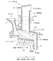
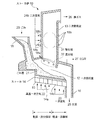
図1は本発明の実施例1に係るストーカ炉の概略断面図、図2は図1のストーカ炉のA−A線断面図(a)、B−B線断面図(b)、図3は本発明の実施例2に係るストーカ炉の概略断面図である。
Hereinafter, exemplary embodiments of the present invention will be described in detail with reference to the drawings. However, the dimensions, materials, shapes, relative arrangements, and the like of the components described in this embodiment are not intended to limit the scope of the present invention unless otherwise specified, but are merely illustrative examples. Not too much.
1 is a schematic cross-sectional view of a stoker furnace according to a first embodiment of the present invention, FIG. 2 is a cross-sectional view of the stoker furnace in FIG. 1 taken along line AA (a), a cross-sectional view of line BB (b), and FIG. It is a schematic sectional drawing of the stoker furnace which concerns on Example 2 of this invention.
図1において、本実施例に係るストーカ炉10は、ごみ20を受け入れて所定量ずつ炉内に供給するごみ投入ホッパ11と、ごみ20が積層されたごみ層21を移送するストーカ14を具備し、ごみを乾燥、熱分解、溶融/焙焼する一次燃焼室12と、該一次燃焼室12の上方に設けられ、燃焼により発生した排ガス中に含まれる未燃分を二次燃焼する二次燃焼室13と、を主要構成とする。
前記一次燃焼室12には、ストーカ14の下部より空気過剰率0.5以下で一次空気22、23を導入する一次空気導入口15が複数設けられ、前記ストーカ14のごみ移送方向上流側と下流側とに独立して一次空気22、23を供給する構成となっている。
In FIG. 1, a stalker furnace 10 according to the present embodiment includes a
The primary combustion chamber 12 is provided with a plurality of
前記ストーカ14は固定段と可動段が交互に配置された構造を有し、該ストーカ14の上流側に位置する上流側ストーカ14aは、ごみ投入ホッパ11より供給されたごみ層21に高温一次空気22を導入し、乾燥と部分燃焼による熱分解を惹起させてガス化する第1の燃焼域(乾燥・熱分解域)を形成する。該第1の燃焼域の上流側部位ではごみの乾燥による多量の水蒸気と未燃ガスを放出し、その下流側部位では前記未燃ガスを着火、輝炎燃焼させる。前記高温一次空気22の条件は、前記ごみ層21の下部から着火して上方に向けて燃焼が進行し、ごみ層21の表層に未燃分が残留するような温度、酸素濃度、空気過剰率とする。好適には、温度約200〜400℃、酸素濃度8〜21%、好ましくは酸素濃度約8〜15%、水蒸気濃度0〜15%、空気過剰率0.1〜0.5とする。
The stoker 14 has a structure in which a fixed stage and a movable stage are alternately arranged. The
本実施例において、前記高温一次空気22は、例えば前記一次燃焼室12より排出されるEGR(燃焼排ガス)27、空気、ボイラ蒸気のうち少なくとも2以上を組み合わせ、これらの配分比を調整することにより前記条件の高温一次空気22を生成することが好ましい。さらに、生成した一次空気が所定温度に達しない場合には、外部に併設したヒータ、又は前記ストーカ炉10の排ガスを利用した熱交換器等により昇温する。
このように、前記高温一次空気22の温度を約200〜400℃とすることで、ごみ層21の下部から着火することができ、主として上方に向けて燃焼反応が進行するため、燃焼が短時間で行なわれ、さらに炉のコンパクト化が図れる。勿論、ごみ層21を吹き抜けた高温一次空気22によりごみ層21の表層からの燃焼も同時に進行する。
また、本実施例のように、ごみ層21の下部より着火させた場合には、火炎面より上側のごみ層21は、火炎からの高温、低酸素濃度ガスが供給されるため熱分解ガス化が促進される。
In this embodiment, the high-temperature primary air 22 is obtained by combining at least two of the EGR (combustion exhaust gas) 27, air, and boiler steam discharged from the primary combustion chamber 12, and adjusting the distribution ratio thereof. It is preferable to generate the high temperature primary air 22 having the above conditions. Further, when the generated primary air does not reach a predetermined temperature, the temperature is raised by an external heater or a heat exchanger using the exhaust gas from the stoker furnace 10 or the like.
In this way, by setting the temperature of the high temperature primary air 22 to about 200 to 400 ° C., it is possible to ignite from the lower part of the dust layer 21, and the combustion reaction proceeds mainly upward, so that the combustion takes a short time. The furnace can be made more compact. Of course, combustion from the surface layer of the dust layer 21 also proceeds at the same time by the high temperature primary air 22 blown through the dust layer 21.
Further, as in this embodiment, when ignited from the lower part of the dust layer 21, the dust layer 21 above the flame surface is supplied with high temperature, low oxygen concentration gas from the flame, so that it is pyrolyzed and gasified. Is promoted.
また、前記高温一次空気22の酸素濃度を21%以下とすることで、ごみ層21の火炎面での緩慢燃焼を達成することができる。これにより、急激な燃焼によって生じる局所的酸素不足領域が減少するため、排ガスへのダイオキシン類、NOX等の有害物質の発生を抑制できる。さらに、酸素濃度を8%以下に下げ過ぎないことで火炎面温度を高く保ち、ごみ層21内の鉛等の重金属類を気化させることができる。ごみ層21から重金属類が除去されることにより、主灰の再利用が可能となる。
さらにまた、前記高温一次空気22には水蒸気を含有させることが好ましく、該水蒸気の作用によりごみ層21の熱分解反応時に発生するタール類のガス化が促進されるため、クリーンな燃焼が実現可能である。
Further, by setting the oxygen concentration of the high temperature primary air 22 to 21% or less, slow combustion on the flame surface of the dust layer 21 can be achieved. Thereby, the local oxygen deficiency region generated by the rapid combustion is decreased, dioxins into the exhaust gas, the generation of harmful substances such as NO X can be suppressed. Furthermore, the flame surface temperature can be kept high by not reducing the oxygen concentration too much to 8% or less, and heavy metals such as lead in the dust layer 21 can be vaporized. By removing heavy metals from the dust layer 21, the main ash can be reused.
Furthermore, it is preferable that the high-temperature primary air 22 contains water vapor, and the action of the water vapor promotes gasification of tars generated during the thermal decomposition reaction of the dust layer 21, so that clean combustion can be realized. It is.
また本実施例では、前記上流側ストーカ14aにてストーカ下部から上方に向けて燃焼を進行させ、未燃分がごみ層21の表層に残留する構成としている。残留させる未燃分量は、下流側ストーカ14bにおける焼却残渣の焙焼、溶融に要する燃焼熱を保有する未燃分量とする。
前記一次燃焼室の下流側に位置する下流側ストーカ14bには第2の燃焼域(焙焼・溶融域)が形成されている。該下流側ストーカ14bでは、ストーカ下部より導入される空気、または、酸素富化した一次空気23により、前記未燃分が燃焼して焼却残渣が加熱され、焼却残渣に含まれる鉛等の重金属類が気化する。ここで、焼却残渣中に含まれる有害物質が除去された主灰25は、灰出しシュート16より排出される。
前記下流側ストーカ14bに導入される空気、または、酸素富化した一次空気23は、温度が常温〜400℃、酸素濃度約21〜30%、空気過剰率0.1〜0.5とすることが好適である。
Further, in this embodiment, the
A second combustion zone (roasting / melting zone) is formed in the
It is preferable that the air introduced into the
また、本実施例1における特徴的な構成として、前記二次燃焼室13のうち、ストーカ上のごみ層21の直上に還元域32を形成し、さらにその上方に酸化域31を形成している。
前記還元域32には、二次空気噴出ノズル18aが複数設けられており、該二次空気噴出ノズル18aから炉内に空気過剰率約0.1〜0.6、好ましくは空気過剰率0.3程度の二次空気24a(図2参照)が導入される。該二次空気24aは、前記一次燃焼室12より炉外へ排出されたEGR(燃焼排ガス)27を用いることもでき、また空気に該EGRを混入させたものを配分比を調整して用いることもできる。
前記酸化域31には、二次空気噴出ノズル18bが複数設けられており、該二次空気噴出ノズル18bから炉内に空気過剰率約0.3〜0.7、好ましくは空気過剰率0.5程度の二次空気24bが導入される。
尚、本実施例にて、炉内に供給される全空気比は1.3程度であることが好ましい。
Further, as a characteristic configuration in the first embodiment, a
A plurality of secondary
A plurality of secondary
In this embodiment, the total air ratio supplied to the furnace is preferably about 1.3.
前記還元域32及び前記酸化域31の断面図を図2に示す。図2(a)は前記ストーカ炉10のA−A線断面図である。前記還元域32に設置される二次空気噴出ノズル18aは、前記ごみ層21の移送方向に対して側面側の炉壁に設けられており、該前記廃棄物層にほぼ平行な直線状に複数列置されるとともに、対面する二次空気噴出ノズル18aが夫々交互に位置するようにくし状に配置されると良い。これによりごみ層21の上方を覆うごとくエアーカーテンが形成され、ごみ層21からのガスと二次空気24aが十分混合される。
また、図2(b)は前記ストーカ炉10のB−B線断面図である。前記酸化域31に設置される二次空気噴出ノズル18bは、前記還元域32の二次空気噴出ノズル18aと略直交する方向に配設されることが好ましい。これにより、炉内ガスの撹拌混合が促進される。
A sectional view of the
FIG. 2B is a cross-sectional view of the stoker furnace 10 taken along the line BB. The secondary
前記還元域32では、炉内ガスに含まれる窒素成分をもつ化合物を熱分解させてNOXを低減し、前記酸化域31にて必要な酸素を供給して未燃分の二次燃焼を行なう。このように、前記還元域32と前記酸化域31とを具備する構成とすることにより、2段燃焼が達成され、脱硝効果によりNOXの発生を最小限に抑えることが可能となる。
また、前記二次空気噴出ノズル18a、18bの配置を上記した構成とすることにより、炉内ガスと二次空気との撹拌混合が促進され、2段燃焼の効果が十分に発揮されるとともに、未燃分の二次燃焼を促進でき、NOX、ダイオキシン類等の有害成分を低減できる。
さらにまた、本実施例では前記一次空気の空気過剰率を約0.5以下と極めて小さい値に設定しているため、前記還元域32の還元性雰囲気を容易に形成でき、NOXの低減に寄与する。
前記二次燃焼室13から排出される排ガス26は、後段の排ガス処理設備(不図示)に送給され、冷却、除塵等の処理が施され、外部へ放出される。
In the
Also, by arranging the secondary
Furthermore, in the present embodiment is set to an extremely small value of about 0.5 or less excess air ratio of the primary air, can be easily formed a reducing atmosphere in the reducing
The exhaust gas 26 discharged from the
図3に本実施例2に係るストーカ炉10を示す。本実施例2では前記実施例1と同様に、ごみ投入ホッパ11より炉内に供給されたごみ20は、ストーカ14上に積層されたごみ層21を形成し、該ごみ層21はストーカ下部より供給される一次空気22、23により乾燥、熱分解、焙焼、溶融され、主灰25は灰出しシュート16より排出される。
一方、前記一次燃焼室12にて発生した排ガスは、該一次燃焼室12の上方に設けられた二次燃焼室13に導かれ、二次空気の導入により二次燃焼される。尚、本実施例2において、前記実施例1と同様の構成については詳細な説明を省略する。
FIG. 3 shows a stoker furnace 10 according to the second embodiment. In the second embodiment, as in the first embodiment, the waste 20 supplied into the furnace from the
On the other hand, the exhaust gas generated in the primary combustion chamber 12 is guided to a
本実施例2の特徴とする構成は、前記二次燃焼室13のうち、上流側ストーカ14aのごみ層21の直上に二次空気噴出ノズル18aを設け、該二次空気噴出ノズル18aから導入する二次空気24aにより還元域32を形成するとともに、前記還元域32の上方に二次空気噴出ノズル18bを設け、該二次空気噴出ノズル18bから導入する二次空気24bにより酸化域31を形成した構成である。これらの二次空気噴出ノズル18a、18bから導入する二次空気条件は前記実施例1と同様とする。また、好ましくは前記上流側ストーカ14aと下流側ストーカ14bの上方空間を分離するごとく隔壁を設けると良い。
このように、還元域32を一次燃焼室12の上流側に集中させることで、ストーカ上流のみから発生する高濃度の未燃ガスを効果的に二次空気と混合させることができる。
The configuration characteristic of the second embodiment is that a secondary
In this way, by concentrating the
本実施例に示した下流側ストーカ14bを、キルン式焙焼炉、エコバーナを具備するバーナ式焙焼炉、固定床のバーナ加熱による表面溶融炉のうち何れかに置き換えることも可能である。
The
10 ストーカ炉
11 投入ホッパ
12 一次燃焼室
13 二次燃焼室
14 ストーカ
14a 上流側ストーカ
14b 下流側ストーカ
15 一次空気導入口
18a、18b 二次空気噴出ノズル
22、 高温一次空気
23 空気、または、酸素富化一次空気
24a、24b 二次空気
31 酸化域
32 還元域
DESCRIPTION OF SYMBOLS 10
Claims (9)
前記二次燃焼室のうち廃棄物層の直上に二次空気を導入して還元域を形成し、該還元域で前記未燃ガスの燃焼を行なった後に、前記還元域の上方に前記二次空気より空気過剰率が大である二次空気を導入して酸化域を形成し、該酸化域で前記未燃ガスの再燃焼を行なうことを特徴とするストーカ炉における廃棄物燃焼方法。 In the primary combustion chamber provided above the stoker, high-temperature primary air is introduced from the lower part of the stoker at an excess air ratio of about 0.5 or less, mainly to thermally decompose waste, and to the secondary combustion chamber provided above the primary combustion chamber. In a waste combustion method in a stoker furnace in which unburned gas generated from the primary combustion chamber in the combustion chamber is subjected to secondary combustion by introducing secondary air,
In the secondary combustion chamber, secondary air is introduced directly above the waste layer to form a reduction zone, and after burning the unburned gas in the reduction zone, the secondary air is placed above the reduction zone. A waste combustion method in a stoker furnace, wherein secondary air having an excess air ratio larger than that of air is introduced to form an oxidation zone, and the unburned gas is reburned in the oxidation zone.
前記二次燃焼室には、廃棄物層の直上に設けられた二次空気導入口から二次空気が導入されて還元域が形成されるとともに、前記還元域の上方に設けられた二次空気導入口から前記二次空気より空気過剰率が大である二次空気が導入されて酸化域が形成されていることを特徴とするストーカ炉。 A primary combustion chamber is provided above the stoker. In the primary combustion chamber, high-temperature primary air is introduced from the lower portion of the stoker at an air ratio of about 0.5 or less to mainly thermally decompose waste. Above the primary combustion chamber, the primary combustion chamber is located above the primary combustion chamber. In a stoker furnace provided with a secondary combustion chamber in which unburned gas generated from the combustion chamber is subjected to secondary combustion by introducing secondary air,
In the secondary combustion chamber, secondary air is introduced from a secondary air inlet provided directly above the waste layer to form a reduction zone, and secondary air provided above the reduction zone. A stoker furnace characterized in that secondary air having an excess air ratio larger than that of the secondary air is introduced from an inlet to form an oxidation zone.
A plurality of secondary air inlets in the reduction zone are provided on the side wall of the furnace with respect to the transfer direction of the waste, and a plurality of secondary air inlets are arranged in a straight line substantially parallel to the waste layer. 6. The stoker furnace according to claim 5, wherein the secondary air inlets facing each other are arranged so as to be alternately arranged.
Priority Applications (1)
| Application Number | Priority Date | Filing Date | Title |
|---|---|---|---|
| JP2004112131A JP2005299939A (en) | 2004-04-06 | 2004-04-06 | Waste combustion method in stoker furnace, and stoker furnace |
Applications Claiming Priority (1)
| Application Number | Priority Date | Filing Date | Title |
|---|---|---|---|
| JP2004112131A JP2005299939A (en) | 2004-04-06 | 2004-04-06 | Waste combustion method in stoker furnace, and stoker furnace |
Publications (1)
| Publication Number | Publication Date |
|---|---|
| JP2005299939A true JP2005299939A (en) | 2005-10-27 |
Family
ID=35331689
Family Applications (1)
| Application Number | Title | Priority Date | Filing Date |
|---|---|---|---|
| JP2004112131A Withdrawn JP2005299939A (en) | 2004-04-06 | 2004-04-06 | Waste combustion method in stoker furnace, and stoker furnace |
Country Status (1)
| Country | Link |
|---|---|
| JP (1) | JP2005299939A (en) |
Cited By (2)
| Publication number | Priority date | Publication date | Assignee | Title |
|---|---|---|---|---|
| JP2007292363A (en) * | 2006-04-24 | 2007-11-08 | Plantec Inc | Vertical waste incinerator for industrial waste incineration |
| WO2016039374A1 (en) * | 2014-09-12 | 2016-03-17 | 三菱重工環境・化学エンジニアリング株式会社 | Stoker-type incinerator |
-
2004
- 2004-04-06 JP JP2004112131A patent/JP2005299939A/en not_active Withdrawn
Cited By (6)
| Publication number | Priority date | Publication date | Assignee | Title |
|---|---|---|---|---|
| JP2007292363A (en) * | 2006-04-24 | 2007-11-08 | Plantec Inc | Vertical waste incinerator for industrial waste incineration |
| WO2016039374A1 (en) * | 2014-09-12 | 2016-03-17 | 三菱重工環境・化学エンジニアリング株式会社 | Stoker-type incinerator |
| JP2016057039A (en) * | 2014-09-12 | 2016-04-21 | 三菱重工環境・化学エンジニアリング株式会社 | Stoker incinerator |
| CN106687744A (en) * | 2014-09-12 | 2017-05-17 | 三菱重工环境·化学工程株式会社 | Stoker-type incinerator |
| CN106687744B (en) * | 2014-09-12 | 2019-01-29 | 三菱重工环境·化学工程株式会社 | Feeding incinerator |
| US10386064B2 (en) | 2014-09-12 | 2019-08-20 | Mitsubishi Heavy Industries Environmental & Chemical Engineering Co., Ltd. | Stoker-type incinerator |
Similar Documents
| Publication | Publication Date | Title |
|---|---|---|
| EP0445070B1 (en) | Process and apparatus for emission reduction from waste incineration | |
| CA2222819C (en) | Method and device for producing and utilizing gas from waste materials | |
| WO2004092648A1 (en) | Method of controlling combustion of waste incinerator and waste incinerator | |
| JP5180917B2 (en) | Waste melting treatment method and waste melting treatment apparatus | |
| EP0432293B1 (en) | Method for recovering waste gases from coal combustor | |
| KR100513932B1 (en) | A pyrolyser heating wastes directly by exhaust gas of a melting furnace and the pyrolysis process using the pyroser | |
| JP5510782B2 (en) | Waste melting treatment method and waste melting treatment apparatus | |
| JP2003166705A (en) | Waste treatment method and apparatus by stoker furnace | |
| KR20090103319A (en) | A Pyrolyser and Pyrolysis Process Using Exhaust Gas of Waste | |
| JP4015026B2 (en) | Advanced NOx reduction method for boilers | |
| JP2013234835A (en) | Gasification melting furnace and method for treating combustible material using the same | |
| JP2008215661A (en) | Combustion furnace, waste gasification system and combustible gas treatment method | |
| JPH07301409A (en) | Method and equipment for simultaneously generating effectivegas and inert inorganic residue and incinerating waste | |
| JP2005299939A (en) | Waste combustion method in stoker furnace, and stoker furnace | |
| CN218972677U (en) | Tail gas incinerator | |
| JP5574475B2 (en) | Waste melting treatment method and waste melting treatment apparatus | |
| JP2004077013A (en) | Operating method of waste incinerator and waste incinerator | |
| JP2003166706A (en) | Combustion method and combustion device of stoker type incinerator | |
| JP2003074819A (en) | Waste melting equipment and its operation method | |
| JP5255509B2 (en) | Waste melting treatment method and waste melting treatment apparatus | |
| JP2007163078A (en) | Waste treatment method and apparatus | |
| JP2004169955A (en) | Waste incinerator and its operation method | |
| JP5534500B2 (en) | Waste treatment method and waste treatment facility | |
| JP2019190729A (en) | Waste combustion device and waste combustion method | |
| JP2004077087A (en) | Waste incinerator |
Legal Events
| Date | Code | Title | Description |
|---|---|---|---|
| A300 | Withdrawal of application because of no request for examination |
Free format text: JAPANESE INTERMEDIATE CODE: A300 Effective date: 20070703 |