JP2005299928A - Molded plastic gasket - Google Patents
Molded plastic gasket Download PDFInfo
- Publication number
- JP2005299928A JP2005299928A JP2005110411A JP2005110411A JP2005299928A JP 2005299928 A JP2005299928 A JP 2005299928A JP 2005110411 A JP2005110411 A JP 2005110411A JP 2005110411 A JP2005110411 A JP 2005110411A JP 2005299928 A JP2005299928 A JP 2005299928A
- Authority
- JP
- Japan
- Prior art keywords
- gasket
- sealing bead
- beads
- gasket according
- sealing
- Prior art date
- Legal status (The legal status is an assumption and is not a legal conclusion. Google has not performed a legal analysis and makes no representation as to the accuracy of the status listed.)
- Pending
Links
- 239000002991 molded plastic Substances 0.000 title description 4
- 239000011324 bead Substances 0.000 claims abstract description 125
- 238000007789 sealing Methods 0.000 claims abstract description 70
- 239000002861 polymer material Substances 0.000 claims abstract description 3
- 239000000463 material Substances 0.000 claims description 5
- 239000006260 foam Substances 0.000 claims description 2
- 239000012815 thermoplastic material Substances 0.000 claims 4
- 239000011162 core material Substances 0.000 description 6
- 239000007789 gas Substances 0.000 description 6
- 239000004734 Polyphenylene sulfide Substances 0.000 description 4
- 239000003365 glass fiber Substances 0.000 description 4
- 239000004033 plastic Substances 0.000 description 4
- 229920003023 plastic Polymers 0.000 description 4
- 229920000069 polyphenylene sulfide Polymers 0.000 description 4
- IJGRMHOSHXDMSA-UHFFFAOYSA-N Atomic nitrogen Chemical compound N#N IJGRMHOSHXDMSA-UHFFFAOYSA-N 0.000 description 3
- 238000012986 modification Methods 0.000 description 3
- 230000004048 modification Effects 0.000 description 3
- 238000000465 moulding Methods 0.000 description 3
- 238000007493 shaping process Methods 0.000 description 3
- XKRFYHLGVUSROY-UHFFFAOYSA-N Argon Chemical compound [Ar] XKRFYHLGVUSROY-UHFFFAOYSA-N 0.000 description 2
- 239000004677 Nylon Substances 0.000 description 2
- 229920001778 nylon Polymers 0.000 description 2
- 239000007787 solid Substances 0.000 description 2
- 244000043261 Hevea brasiliensis Species 0.000 description 1
- 229920000459 Nitrile rubber Polymers 0.000 description 1
- 229920000299 Nylon 12 Polymers 0.000 description 1
- 239000004952 Polyamide Substances 0.000 description 1
- 229910052786 argon Inorganic materials 0.000 description 1
- 229910001873 dinitrogen Inorganic materials 0.000 description 1
- 239000013536 elastomeric material Substances 0.000 description 1
- 239000012530 fluid Substances 0.000 description 1
- 239000011261 inert gas Substances 0.000 description 1
- 229920003052 natural elastomer Polymers 0.000 description 1
- 229920001194 natural rubber Polymers 0.000 description 1
- 229910052757 nitrogen Inorganic materials 0.000 description 1
- 229920002647 polyamide Polymers 0.000 description 1
- 229920000642 polymer Polymers 0.000 description 1
Images
Classifications
-
- H—ELECTRICITY
- H01—ELECTRIC ELEMENTS
- H01R—ELECTRICALLY-CONDUCTIVE CONNECTIONS; STRUCTURAL ASSOCIATIONS OF A PLURALITY OF MUTUALLY-INSULATED ELECTRICAL CONNECTING ELEMENTS; COUPLING DEVICES; CURRENT COLLECTORS
- H01R31/00—Coupling parts supported only by co-operation with counterpart
- H01R31/06—Intermediate parts for linking two coupling parts, e.g. adapter
-
- F—MECHANICAL ENGINEERING; LIGHTING; HEATING; WEAPONS; BLASTING
- F16—ENGINEERING ELEMENTS AND UNITS; GENERAL MEASURES FOR PRODUCING AND MAINTAINING EFFECTIVE FUNCTIONING OF MACHINES OR INSTALLATIONS; THERMAL INSULATION IN GENERAL
- F16L—PIPES; JOINTS OR FITTINGS FOR PIPES; SUPPORTS FOR PIPES, CABLES OR PROTECTIVE TUBING; MEANS FOR THERMAL INSULATION IN GENERAL
- F16L23/00—Flanged joints
- F16L23/16—Flanged joints characterised by the sealing means
- F16L23/18—Flanged joints characterised by the sealing means the sealing means being rings
- F16L23/22—Flanged joints characterised by the sealing means the sealing means being rings made exclusively of a material other than metal
-
- H—ELECTRICITY
- H01—ELECTRIC ELEMENTS
- H01R—ELECTRICALLY-CONDUCTIVE CONNECTIONS; STRUCTURAL ASSOCIATIONS OF A PLURALITY OF MUTUALLY-INSULATED ELECTRICAL CONNECTING ELEMENTS; COUPLING DEVICES; CURRENT COLLECTORS
- H01R2107/00—Four or more poles
-
- H—ELECTRICITY
- H01—ELECTRIC ELEMENTS
- H01R—ELECTRICALLY-CONDUCTIVE CONNECTIONS; STRUCTURAL ASSOCIATIONS OF A PLURALITY OF MUTUALLY-INSULATED ELECTRICAL CONNECTING ELEMENTS; COUPLING DEVICES; CURRENT COLLECTORS
- H01R24/00—Two-part coupling devices, or either of their cooperating parts, characterised by their overall structure
- H01R24/58—Contacts spaced along longitudinal axis of engagement
-
- H—ELECTRICITY
- H01—ELECTRIC ELEMENTS
- H01R—ELECTRICALLY-CONDUCTIVE CONNECTIONS; STRUCTURAL ASSOCIATIONS OF A PLURALITY OF MUTUALLY-INSULATED ELECTRICAL CONNECTING ELEMENTS; COUPLING DEVICES; CURRENT COLLECTORS
- H01R24/00—Two-part coupling devices, or either of their cooperating parts, characterised by their overall structure
- H01R24/60—Contacts spaced along planar side wall transverse to longitudinal axis of engagement
Landscapes
- Engineering & Computer Science (AREA)
- General Engineering & Computer Science (AREA)
- Mechanical Engineering (AREA)
- Gasket Seals (AREA)
- Sealing With Elastic Sealing Lips (AREA)
Abstract
Description
本発明はガスケットに関し、より詳しくは、成形プラスチックガスケットに関する。 The present invention relates to gaskets, and more particularly to molded plastic gaskets.
ガスケットは、長年に亘って、相対的に静止している2つの部材間のシール連結を形成するのに使用されている。ガスケットが有効シールを形成するには、ガスケットは、一般に、シールすべき部材間に圧縮荷重を必要とする。例えば、エンジンブロックとオイルパンとの間、またはエンジンのシリンダヘッドとバルブ/カムカバーとの間のような2つの静止部材間に配置されるガスケットは、これらの要素間で圧縮される。 Gaskets have been used for many years to form a seal connection between two members that are relatively stationary. In order for a gasket to form an effective seal, the gasket generally requires a compressive load between the members to be sealed. For example, a gasket placed between two stationary members, such as between an engine block and an oil pan, or between an engine cylinder head and a valve / cam cover, is compressed between these elements.
1つのガスケット設計として、中央サービス孔を包囲する中実成形シーリングビードを備えた成形プラスチック本体がある。中実成形シーリングビードは、優れたシールを確保するには大きいクランプ力を必要とする。高クランプ力により高圧縮力が生じ、これによりプラスチックの経時変形が引起こされ、従ってシールの有効性が低下する。 One gasket design is a molded plastic body with a solid molded sealing bead surrounding the central service hole. Solid molded sealing beads require a large clamping force to ensure an excellent seal. A high clamping force results in a high compressive force, which causes plastic deformation over time, thus reducing the effectiveness of the seal.
従って、変形傾向が小さいシーリングビードを備えたガスケットが要望されている。 Accordingly, there is a need for a gasket having a sealing bead that has a low tendency to deform.
本発明は、少なくとも1つのサービス孔が形成された本体を備えたガスケットを提供する。シーリングビードは本体と一体に形成されかつサービス孔を包囲している。シーリングビードは、外方に延びている第一セグメントと、該第一セグメントに対向する第一凹状チャネルとを有している。第一凹状チャネルは、外方に延びている第二セグメントおよび外方に延びている第三セグメントにより形成されている。 The present invention provides a gasket with a body having at least one service hole formed therein. The sealing bead is integrally formed with the main body and surrounds the service hole. The sealing bead has a first segment extending outwardly and a first concave channel facing the first segment. The first concave channel is formed by a second segment extending outward and a third segment extending outward.
また本発明は、ガスケットが、少なくとも1つのサービス孔が形成されかつシーリングヘッドが一体に形成された本体を有している構成の一変更形態を提供する。シーリングヘッドは、本体に一体成形された環状シーリング部材を有し、該環状シーリング部材は外方に突出したシーリングビードセグメントに対向して配置されている。 The present invention also provides a modification of the configuration in which the gasket has a main body in which at least one service hole is formed and a sealing head is integrally formed. The sealing head has an annular sealing member formed integrally with the main body, and the annular sealing member is arranged to face the sealing bead segment protruding outward.
第二変更形態では、本発明は、少なくとも1つのサービス孔が形成された本体と、該本体と一体に形成されたシーリングビードとを有するガスケットを提供する。シーリングビードは、加圧ガスが充填される内部チャンバを有している。 In a second variation, the present invention provides a gasket having a body formed with at least one service hole and a sealing bead formed integrally with the body. The sealing bead has an internal chamber that is filled with pressurized gas.
ガスケットの第三変更形態は、第一ポリマー材料からなりかつ少なくとも1つのサービス孔が形成された本体を有している。本体には、シーリングビードが一体に形成されており、該シーリングビードは第二ポリマー材料が充填されるチャンバを形成している。 A third variation of the gasket has a body made of a first polymer material and having at least one service hole formed therein. The body is integrally formed with a sealing bead that forms a chamber filled with a second polymeric material.
本発明の他の適用領域は、以下に述べる詳細な説明から明らかになるであろう。本発明の好ましい実施形態を示す詳細な説明および特定例は、例示のみを目的とするものであって、本発明の範囲を限定するものではないことを理解すべきである。 Other areas of applicability of the present invention will become apparent from the detailed description provided hereinafter. It should be understood that the detailed description and specific examples, while indicating the preferred embodiment of the invention, are intended for purposes of illustration only and are not intended to limit the scope of the invention.
本発明は、以下の詳細な説明および添付図面からより完全に理解されよう。 The invention will be more fully understood from the following detailed description and the accompanying drawings.
好ましい実施形態についての以下の説明は本質の単なる例示であり、いかなる意味においても本発明、その用途または使用方法を限定するものではない。 The following description of the preferred embodiment is merely exemplary in nature and is not intended to limit the invention, its application, or uses in any way.
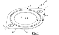
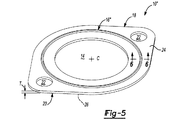
ここで図1を参照すると、本発明の原理によるガスケット10が示されている。ガスケット10の形状は例示のみを目的とするものであって、本発明の範囲を限定するものではないと理解されたい。図1〜図8に示すガスケット10を説明するが、これらの図面において同一または類似の要素を示すのに共通の参照番号が使用されている。概略的には、ガスケット10は、サービス孔14およびシーリングビード部分16を備えた本体12を有している。
Referring now to FIG. 1, a
図1〜図8に概略的に示すように、サービス孔14は、一般に、中心線Cに沿って本体12の中央に形成される。好ましくは、本体12は、自動車に使用する流体に対する優れた可撓性、抵抗性およびエンジン温度に対する抵抗性を有する例えばガラス繊維充填ポリアミド(または他のナイロン)またはガラス繊維充填ポリフェニレンスルフィド(PPS)等の耐熱性ポリマーから全体的に成形される。本体12は更に、第一端部18と、第二端部20と、厚さTとを有している。また第一端部18および第二端部20の各々は取付け孔22を有し、該取付け孔22は、これに挿通される例えばボルトまたはねじを受入れる。本体12はまた、第一表面24および第二表面26を有している。本体12はリング状のものが示されておりかつサービス孔14は円形のものが示されているが、シールすべき表面のサイズおよび形状に基いて他の形状を使用できることを理解すべきである。また、取付け孔22の数も、シールすべき表面のサイズおよび形状に基いて変えることができる。
As schematically shown in FIGS. 1 to 8, the
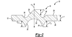
特に図1および図2に示す一実施形態では、シーリングビード部分16がサービス孔14を包囲しかつ本体12と一体に形成されている。図2に示すように、シーリングビード部分16は外方に延びている第一ビード28を有し、該第一ビード28は、本体12の第一表面24を越えて突出している。この外方に延びている第一セグメント28は、本体12の厚さTにほぼ等しい高さH1を有している。第一ビード28は、本体12の第二表面26に形成された第一凹状チャネル30に対向して配置されている。第一凹状チャネル30は、この一部が、外方に延びている第二ビード32および外方に延びている第三ビード34により形成されている。チャネル30の深さは、第二ビード32および第三ビード34のいずれか一方または両方の高さより大きくすることができる。第二ビード32および第三ビード34は、両方とも本体12の第二表面26上に形成されている。第二ビードは高さH2を有し、第三ビード34は高さH3を有している。一般に高さH2および高さH3は実質的に同じであるが、特定用途に従って両高さH2、H3を異ならせることができることに留意されたい。この実施形態では、両高さH2、H3のサイズは、本体12の厚さTにほぼ等しい。
In particular, in one embodiment shown in FIGS. 1 and 2, the
外方に延びている第二および第三ビード32、34も、それぞれ、第二および第三凹状チャネル36、38にほぼ対向して配置されている。第二および第三凹状チャネル36、38は、外方に延びている第一ビード28の両側で本体12の第一表面24に形成されている。この実施形態のシーリングビード部分16は、該部分16がシールの有効性を変えることなく圧力を受けて僅かに変形することを可能にする第一、第二および第三チャネル30、36、38を介して気密シールを確保する。外方に延びているビード28、32または34のいずれも、断面形状がほぼ三角形、円形、矩形または当業者が考え得る他の種々の断面形状にすることができる。これらのビードの全部またはいずれかは、本体12に対して同じ高さにすることができ、或いは、本体12に対する1つ以上のこれらのビードの高さを、1つ以上の他のいずれかのビードの高さとは異ならせることもできる。
The outwardly extending second and
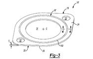
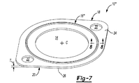
図3および図4には、他の実施形態によるガスケット10’が示されている。この実施形態では、シーリングビード部分16’が環状リング100を有し、該リング100内に圧縮可能リング102が受入れられる。圧縮可能リング102はシーリングビード部分16’と一体に形成するか、後工程で環状チャネル100に取付けることができる。圧縮可能リング102は、小さい圧縮応力弛緩を呈する例えば天然ゴムまたはニトリルゴム等の任意のエラストマー材料で形成できる。
3 and 4 show a gasket 10 'according to another embodiment. In this embodiment, the
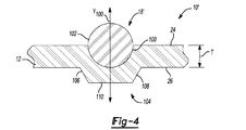
圧縮可能リング102に対向して、外方に延びているビード104が配置されている。ビード104は、ほぼ平らな頂部110から延びている第一傾斜側壁106および第二傾斜側壁108を有している。ビード104は、本体12の第二表面26から延びている。シーリングビード部分16’は、該部分16’のY軸線Y100の回りでほぼ対称的である。ビード104は多角形のものが示されているが、ビード104の形状は特定シーリング用途に従って変えることができることに留意されたい。シーリングビード部分16’の構造は、圧縮可能リング102の使用により、撓みに対する抵抗を付与する。より詳しくは、圧縮可能リング102はクランピングに対する弾性応力面を形成し、経時シールの有効性を確保する。
Opposed to the
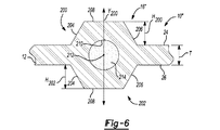
ここで、特に図5および図6を参照すると、第二変更形態によるガスケット10”が示されている。この実施形態では、シーリングビード部分16”は、本体12と一体に形成された外方に延びている第一ビード200および外方に延びている第二ビード202を有している。シーリングビード部分16”は、該部分16”のY軸線Y200の回りでほぼ対称的である。第一および第二ビード200、202の各々が、ほぼ平らな頂部208から延びている第一傾斜側壁204および第二傾斜側壁206を有している。外方に延びている第一ビード200は本体12の第一表面24から延びており、一方、外方に延びている第二ビード202は本体12の第二表面26から延びている。第一ビード200は高さH200を有し、第二ビード202は高さH202を有している。高さH200、H202は本体12の厚さTとほぼ同じであるが、特定用途に基いて、厚さTより大きくまたは小さくすることもできる。第一および第二ビード200、202は多角形のものが示されているが、両ビード200、202の形状は特定シーリング用途に従って変えることができる。
With particular reference now to FIGS. 5 and 6, a
第一および第二ビード200、202は互いにほぼ対向して配置されており、かつ本体12の中央212に環状チャネル210を形成している。チャネル210は、加圧ガス214を受入れるように構成されている。環状チャネル210内に収容される加圧ガス214として、窒素、アルゴンまたは他の不活性ガスを使用できる。加圧ガス214はシーリングビード内に収容される。
The first and
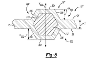
図7および図8には、本発明の第三変更形態によるガスケット10” ’が示されている。この実施形態のシーリングビード部分16” ’は本体12と一体に形成されておりかつ外方に延びている第一ビード300および外方に延びている第二ビード302を有している。第一および第二ビード300、302は、シーリングビード部分16” ’のY軸線Y300に関してほぼ対称的である。第一ビード300は本体12の第一表面24から延びており、一方、第二ビード302は本体12の第二表面26から延びている。第一および第二ビード300、302の各々は、第一傾斜側壁306と第二傾斜側壁308との間で延びている頂セグメント304を有している。第一ビード300は高さH300を有し、第二ビード302は高さH302を有している。高さH300、H302は本体12の厚さTより僅かに大きいが、特定用途に基いて、厚さTより小さくすることもできる。第一および第二ビード300、302は多角形のものが示されているが、両ビード300、302の形状並びにサイズは特定シーリング用途に従って変えることができる。
7 and 8 show a
外方に延びている第一および第二ビード300、302には、コア材料312を収容するための内部チャンバ310が形成されている。コア材料312は、可撓性および弾性を付与する窒素ガスの微孔ポケットを有するガラス繊維充填ポリアミド12(または他のナイロン)またはガラス繊維充填ポリフェニレンスルフィド(PPS)または他の同様な適当な材料からなる微孔発泡体で形成できる。コア材料312は内部チャンバ310内に収容されているところが示されているが、本体12の実質的に全体に配置できることにも留意されたい。コア材料312は弾性クランピング箇所を形成し、シールが経時一体性を維持することを可能にする。
The first and
概略的にいえば、本発明のガスケット10は、弾性クランピング箇所を設けることにより経時気密シールを確保する。より詳しくは、3つの凹状チャネル30、36、38はシーリング力を低下させることなく僅かに変形することを可能にし、一方、圧縮可能リング102、加圧ガス214およびコア材料312は、弾性シーリングビードを形成する。
Generally speaking, the
本発明の上記説明は本質の単なる例示であり、従って、本発明の本旨から逸脱しない変更は本発明の範囲内に包含されるものであり、そのような変更は本発明の精神および範囲から逸脱しないと考えるべきである。 The foregoing description of the invention is merely exemplary in nature and, thus, variations that do not depart from the spirit of the invention are intended to be included within the scope of the invention, and such variations depart from the spirit and scope of the invention. Should not be considered.
10、10’、10”、10” ’ ガスケット
12 本体
14 サービス孔
16、16’、16”、16” ’ シーリングビード部分
30、36、38 凹状チャネル
100、210 環状チャネル
102 圧縮可能リング
204、206、306、308 傾斜側壁
214 加圧ガス
310 内部チャンバ
312 コア材料
10, 10 ', 10 ", 10"'
Claims (34)
前記本体と一体でかつサービス孔を包囲しているシーリングビード部分を更に有し、該シーリングビード部分は、前記第一表面から外方に延びている第一ビードおよび該第一ビードに対向して前記第二表面に形成された第一凹状チャネルを備え、該第一凹状チャネルは、前記第二表面から外方に延びている第二ビードと同じく前記第二表面から外方に延びている第三ビードとの間に配置されていることを特徴とするガスケット。 Having a body with first and second surfaces, the body having at least one service hole formed therethrough,
A sealing bead portion integral with the body and surrounding the service hole, the sealing bead portion extending outwardly from the first surface and opposite the first bead; A first concave channel formed on the second surface, the first concave channel extending outward from the second surface in the same manner as a second bead extending outward from the second surface; A gasket characterized by being disposed between three beads.
第一端部と、
該第一端部に対向する第二端部と、
第一端部および第二端部の少なくとも1つに設けられた少なくとも1つの取付け孔とを有することを特徴とする請求項1記載のガスケット。 The body further includes
A first end;
A second end opposite the first end;
The gasket according to claim 1, further comprising at least one mounting hole provided in at least one of the first end and the second end.
前記外方に延びている第三ビードに対向する第三凹状チャネルとを更に有することを特徴とする請求項1記載のガスケット。 A second concave channel facing the outwardly extending second bead;
The gasket of claim 1, further comprising a third concave channel facing the outwardly extending third bead.
本体と一体に形成されかつサービス孔を包囲しているシーリングビード部分とを有し、該シーリングビード部分は、ガスが充填される内部チャンバを形成していることを特徴とするガスケット。 A body formed with at least one service hole;
A gasket having a sealing bead portion formed integrally with the main body and surrounding the service hole, wherein the sealing bead portion forms an internal chamber filled with gas.
前記本体の第一表面から外方に延びている第一シーリングビードを有し、該第一シーリングビードは、本体の第一表面に対して実質的に平行な頂セグメントに連結された1対の傾斜側壁を備え、
前記本体の第二表面から外方に延びている第二シーリングビードを有し、該第二シーリングビードは、本体の第二表面に対して実質的に平行な頂セグメントに連結された1対の傾斜側壁を備えていることを特徴とする請求項17記載のガスケット。 The sealing bead portion further includes
A first sealing bead extending outwardly from the first surface of the body, the first sealing bead coupled to a top segment substantially parallel to the first surface of the body. With inclined side walls,
A second sealing bead extending outwardly from the second surface of the body, the second sealing bead coupled to a top segment substantially parallel to the second surface of the body. The gasket according to claim 17, further comprising an inclined side wall.
第一端部と、
該第一端部に対向する第二端部と、
第一端部および第二端部の少なくとも1つに設けられた少なくとも1つの取付け孔とを有することを特徴とする請求項15記載のガスケット。 The body further includes
A first end;
A second end opposite the first end;
The gasket according to claim 15, further comprising at least one attachment hole provided in at least one of the first end and the second end.
該本体と一体に形成されかつサービス孔を包囲しているシーリングビード部分とを有し、該シーリングビード部分は第一ポリマー材料が充填されるチャンバを形成していることを特徴とするガスケット。 A body made of a first polymeric material and having at least one service hole formed thereon;
And a sealing bead portion integrally formed with the body and surrounding the service hole, wherein the sealing bead portion forms a chamber filled with a first polymer material.
前記本体の第一表面から外方に延びている第一シーリングビードを有し、該第一シーリングビードは、本体の第一表面に対して実質的に平行な頂セグメントに連結された1対の傾斜側壁を備え、
前記本体の第二表面から外方に延びている第二シーリングビードを有し、該第二シーリングビードは、本体の第二表面に対して実質的に平行な頂セグメントに連結された1対の傾斜側壁を備えていることを特徴とする請求項24記載のガスケット。 The sealing bead portion further includes
A first sealing bead extending outwardly from the first surface of the body, the first sealing bead coupled to a top segment substantially parallel to the first surface of the body. With inclined side walls,
A second sealing bead extending outwardly from the second surface of the body, the second sealing bead coupled to a top segment substantially parallel to the second surface of the body. The gasket according to claim 24, further comprising an inclined side wall.
第一端部と、
該第一端部に対向する第二端部と、
第一端部および第二端部の少なくとも1つに設けられた少なくとも1つの取付け孔とを有することを特徴とする請求項22記載のガスケット。 The body further includes
A first end;
A second end opposite the first end;
The gasket according to claim 22, further comprising at least one mounting hole provided in at least one of the first end and the second end.
サービス孔を包囲しているシーリングビード部分とを有し、該シーリングビード部分は、本体に成形された環状シーリング部材を備え、
該環状シーリング部材は本体の第一表面に配置されかつ本体の第二表面に形成された、外方に突出しているシーリングビードに対向していることを特徴とするガスケット。 A body formed with at least one service hole;
A sealing bead portion surrounding the service hole, the sealing bead portion comprising an annular sealing member molded into the body,
The gasket is characterized in that the annular sealing member is disposed on the first surface of the main body and faces the outwardly projecting sealing bead formed on the second surface of the main body.
第一端部と、
該第一端部に対向する第二端部と、
第一端部および第二端部の少なくとも1つに設けられた少なくとも1つの取付け孔とを有することを特徴とする請求項29記載のガスケット。 The body further includes
A first end;
A second end opposite the first end;
30. The gasket according to claim 29, further comprising at least one mounting hole provided in at least one of the first end and the second end.
Applications Claiming Priority (1)
| Application Number | Priority Date | Filing Date | Title |
|---|---|---|---|
| US10/819,538 US7121556B2 (en) | 2004-04-07 | 2004-04-07 | Molded plastic gasket |
Publications (1)
| Publication Number | Publication Date |
|---|---|
| JP2005299928A true JP2005299928A (en) | 2005-10-27 |
Family
ID=34912704
Family Applications (1)
| Application Number | Title | Priority Date | Filing Date |
|---|---|---|---|
| JP2005110411A Pending JP2005299928A (en) | 2004-04-07 | 2005-04-07 | Molded plastic gasket |
Country Status (7)
| Country | Link |
|---|---|
| US (1) | US7121556B2 (en) |
| EP (1) | EP1584850A1 (en) |
| JP (1) | JP2005299928A (en) |
| KR (1) | KR20060045519A (en) |
| BR (1) | BRPI0501242A (en) |
| CA (1) | CA2503060A1 (en) |
| TW (1) | TW200535355A (en) |
Cited By (1)
| Publication number | Priority date | Publication date | Assignee | Title |
|---|---|---|---|---|
| KR102237074B1 (en) * | 2019-11-19 | 2021-04-07 | 현대자동차 주식회사 | Intercooler assembly |
Families Citing this family (23)
| Publication number | Priority date | Publication date | Assignee | Title |
|---|---|---|---|---|
| GB0000712D0 (en) * | 2000-01-14 | 2000-03-08 | Flexitallic Ltd | Gasket |
| GB0329890D0 (en) * | 2003-12-23 | 2004-01-28 | Airbus Uk Ltd | Method of Sealing a Joint |
| US20050280214A1 (en) * | 2004-06-22 | 2005-12-22 | Richards Jeffrey L | Elastomer coated screen gasket |
| US9493936B2 (en) | 2004-10-08 | 2016-11-15 | Sdb Ip Holdings, Llc | System, method, and apparatus for monitoring wear in a flush valve using pressure detection |
| US7607448B2 (en) * | 2004-10-08 | 2009-10-27 | I-Con Systems, Inc. | Method for modifying a plastic body valve for use in a waste water system |
| US7735513B2 (en) | 2004-10-08 | 2010-06-15 | I-Con Systems, Inc. | Diaphragm valve with electronic pressure detection |
| GB0500470D0 (en) | 2005-01-11 | 2005-02-16 | Flexitallic Ltd | A gasket material and its process of production |
| EP2005041B1 (en) * | 2006-03-28 | 2012-07-11 | Interface Solutions, Inc. | Gasket formed from various material |
| USD536078S1 (en) * | 2006-03-31 | 2007-01-30 | Emerson Network Power, Energy Systems, North America, Inc. | Condenser shroud cover for DC cooler |
| USD536079S1 (en) * | 2006-03-31 | 2007-01-30 | Emerson Network Power, Energy Systems, North America, Inc. | Evaporator air mover cover for DC cooler |
| USD575381S1 (en) | 2006-03-31 | 2008-08-19 | Emerson Network Power | Condenser shroud for DC cooler |
| USD536077S1 (en) * | 2006-03-31 | 2007-01-30 | Emerson Network Power, Energy Systems, North America, Inc. | Evaporator shroud for DC cooler |
| US20080197582A1 (en) * | 2007-02-19 | 2008-08-21 | Botten Eric M | Outer door handle gasket for automotive vehicles |
| WO2010006561A1 (en) * | 2008-07-16 | 2010-01-21 | Mico, Spol. S.R.O. | Comby two-sided overlain gasket for sealing of dismountable flanged joints |
| US8579299B2 (en) * | 2009-04-03 | 2013-11-12 | Interface Solutions, Inc. | Gasket having adhesive element |
| GB0922625D0 (en) | 2009-12-24 | 2010-02-10 | Flexitallic Ltd | A gasket |
| FR2968533B1 (en) * | 2010-12-08 | 2013-09-06 | Brothier Lab | MEDICAL DEVICE FOR REINFORCING |
| CA2829072C (en) | 2013-10-02 | 2020-03-10 | Canplas Industries Ltd. | Bathtub drain and overflow kit |
| CN104500225A (en) * | 2014-12-12 | 2015-04-08 | 张家港市三林法兰锻造有限公司 | Internal combustion engine connecting plate |
| US10378676B2 (en) | 2015-12-15 | 2019-08-13 | Sdb Ip Holdings, Llc | System, method, and apparatus for optimizing a timing of a flush valve |
| KR20180024205A (en) * | 2016-08-29 | 2018-03-08 | (주)성창 | High Performance Sealing Metal Gasket |
| USD921168S1 (en) * | 2019-05-07 | 2021-06-01 | Wehrli Custom Fabrication, Inc. | Flow directing ring |
| EP4419186A4 (en) * | 2021-10-18 | 2025-04-09 | Colder Products Company | Fluid couplings |
Citations (5)
| Publication number | Priority date | Publication date | Assignee | Title |
|---|---|---|---|---|
| JPS63289376A (en) * | 1987-04-20 | 1988-11-25 | フェル−プロ インコーポレーテッド | Manufacture of gasket |
| JPH01134760U (en) * | 1988-03-09 | 1989-09-14 | ||
| JP2002168350A (en) * | 2000-11-30 | 2002-06-14 | Japan Metal Gasket Co Ltd | Metal gasket |
| WO2004007937A1 (en) * | 2002-07-12 | 2004-01-22 | Uchiyama Manufacturing Corp. | Gasket |
| JP2005003181A (en) * | 2003-06-16 | 2005-01-06 | Nok Corp | gasket |
Family Cites Families (22)
| Publication number | Priority date | Publication date | Assignee | Title |
|---|---|---|---|---|
| FR550298A (en) | 1920-02-20 | 1923-03-02 | Metal seal for pipes, boilers, various containers, etc. | |
| GB380853A (en) | 1931-06-29 | 1932-09-29 | Percy Wills | Improvements in or relating to metal joint washers or gaskets |
| FR1118630A (en) | 1955-02-02 | 1956-06-08 | Watertight seals | |
| US3166332A (en) * | 1961-05-26 | 1965-01-19 | Olson Richard Laurence | Pressure assembly comprising a sealing strip of elastomeric material having compressible gas cells |
| DE1917326A1 (en) | 1968-04-05 | 1969-10-23 | Robert Ford | Sealing ring washer provided with annular protuberances (21-27) around the washer hole (20) these being concentrically and alternatingly arranged on each side |
| US3909019A (en) * | 1972-06-14 | 1975-09-30 | Toma D Leko | Gaskets |
| US4140323A (en) | 1977-09-12 | 1979-02-20 | Felt Products Mfg. Co. | Embossed gasket |
| DE3035581A1 (en) | 1979-09-27 | 1981-04-09 | Neotecha Ag, Hombrechtikon | Plastic seal between solid bodies - has transverse corrugations of constant radius bearing against bodies |
| JPH0414681Y2 (en) | 1986-04-11 | 1992-04-02 | ||
| US5122214A (en) * | 1988-07-18 | 1992-06-16 | Fel-Pro Incorporated | Method of making a rubber laminated gasket |
| US4846482A (en) * | 1988-08-19 | 1989-07-11 | General Motors Corporation | High compliance seal and engine combination |
| US5421594A (en) * | 1991-02-14 | 1995-06-06 | Marine & Petroleum Mfg., Inc. | Gasket |
| US5228702A (en) * | 1992-05-01 | 1993-07-20 | Fel-Pro Incorporated | Molded plastic gasket having a combination sealing bead |
| US5364109A (en) * | 1992-11-13 | 1994-11-15 | Chrysler Corporation | Sealing gasket with hard interior backbone and integral crush limiters |
| US5295698A (en) | 1993-01-29 | 1994-03-22 | Fel-Pro Incorporated | Molded plastic gasket having an improved sealing bead |
| US5785322A (en) | 1993-06-30 | 1998-07-28 | Acadia Elastomers | Gasket for flange connections |
| DE4421219C5 (en) | 1994-02-12 | 2005-07-07 | STE Gesellschaft für Dichtungstechnik mbH | Metallic flat gasket with locally adjustable deformability |
| DE19731492C2 (en) | 1997-07-22 | 2001-07-19 | Reinz Dichtungs Gmbh | Metallic flat gasket |
| JPH11201287A (en) * | 1998-01-12 | 1999-07-27 | Ishikawa Gasket Co Ltd | Gasket and manufacturing method thereof |
| US6231053B1 (en) * | 1999-06-11 | 2001-05-15 | Nok Corporation | Gasket for fuel cell |
| DE19939869A1 (en) | 1999-08-23 | 2001-04-12 | Elringklinger Gmbh | gasket |
| US6769696B2 (en) * | 2001-09-29 | 2004-08-03 | Elringklinger Ag | At least substantially metallic cylinder head gasket |
-
2004
- 2004-04-07 US US10/819,538 patent/US7121556B2/en not_active Expired - Lifetime
-
2005
- 2005-03-02 EP EP05004507A patent/EP1584850A1/en not_active Withdrawn
- 2005-03-30 CA CA002503060A patent/CA2503060A1/en not_active Abandoned
- 2005-03-30 TW TW094109967A patent/TW200535355A/en unknown
- 2005-04-06 KR KR1020050028448A patent/KR20060045519A/en not_active Ceased
- 2005-04-06 BR BR0501242-2A patent/BRPI0501242A/en not_active IP Right Cessation
- 2005-04-07 JP JP2005110411A patent/JP2005299928A/en active Pending
Patent Citations (5)
| Publication number | Priority date | Publication date | Assignee | Title |
|---|---|---|---|---|
| JPS63289376A (en) * | 1987-04-20 | 1988-11-25 | フェル−プロ インコーポレーテッド | Manufacture of gasket |
| JPH01134760U (en) * | 1988-03-09 | 1989-09-14 | ||
| JP2002168350A (en) * | 2000-11-30 | 2002-06-14 | Japan Metal Gasket Co Ltd | Metal gasket |
| WO2004007937A1 (en) * | 2002-07-12 | 2004-01-22 | Uchiyama Manufacturing Corp. | Gasket |
| JP2005003181A (en) * | 2003-06-16 | 2005-01-06 | Nok Corp | gasket |
Cited By (1)
| Publication number | Priority date | Publication date | Assignee | Title |
|---|---|---|---|---|
| KR102237074B1 (en) * | 2019-11-19 | 2021-04-07 | 현대자동차 주식회사 | Intercooler assembly |
Also Published As
| Publication number | Publication date |
|---|---|
| EP1584850A1 (en) | 2005-10-12 |
| KR20060045519A (en) | 2006-05-17 |
| TW200535355A (en) | 2005-11-01 |
| US20050242527A1 (en) | 2005-11-03 |
| BRPI0501242A (en) | 2005-11-16 |
| US7121556B2 (en) | 2006-10-17 |
| CA2503060A1 (en) | 2005-10-07 |
Similar Documents
| Publication | Publication Date | Title |
|---|---|---|
| JP2005299928A (en) | Molded plastic gasket | |
| US9269933B2 (en) | Gasket | |
| US8474829B2 (en) | Sealing device | |
| JP2012154387A (en) | Seal material | |
| JP6653206B2 (en) | Liquid ring vibration isolator | |
| JP5029831B2 (en) | gasket | |
| EP2908034B1 (en) | Sealing device | |
| JP5392442B2 (en) | Gasket and sealing structure | |
| JP5144253B2 (en) | Pump sealing device | |
| JP2005195091A (en) | Gasket | |
| JP2006090463A (en) | Gasket | |
| US11644080B2 (en) | Lquid-filled vibration isolator | |
| KR101425947B1 (en) | Rubber Gasket Structure for Sealing T-joint Portion | |
| JP4691271B2 (en) | gasket | |
| JP2020026885A (en) | Sealing assembly for preventing damage from explosive decompression and block fitting assembly including the same | |
| US20080185247A1 (en) | Sealing structure for self leveling damper utilizing quadrangular-sectioned o-ring | |
| JP2008240889A (en) | Load ring and sealing device | |
| US20250215953A1 (en) | Liquid seal type vibration isolation device | |
| US7861643B2 (en) | Piston device | |
| JP7411221B2 (en) | Seal member | |
| JP2009156276A (en) | Seal structure of cylindrical member | |
| JP2003336601A (en) | Accumulator | |
| CN118517524A (en) | O-ring collar seal | |
| WO2016195757A1 (en) | Variable compression ratio engine gasket | |
| KR20190011427A (en) | Diaphragm Assembly |
Legal Events
| Date | Code | Title | Description |
|---|---|---|---|
| A131 | Notification of reasons for refusal |
Free format text: JAPANESE INTERMEDIATE CODE: A131 Effective date: 20080603 |
|
| A02 | Decision of refusal |
Free format text: JAPANESE INTERMEDIATE CODE: A02 Effective date: 20081118 |