JP2005299879A - Automatic transmission control device - Google Patents
Automatic transmission control deviceInfo
- Publication number
- JP2005299879A JP2005299879A JP2004120210A JP2004120210A JP2005299879A JP 2005299879 A JP2005299879 A JP 2005299879A JP 2004120210 A JP2004120210 A JP 2004120210A JP 2004120210 A JP2004120210 A JP 2004120210A JP 2005299879 A JP2005299879 A JP 2005299879A
- Authority
- JP
- Japan
- Prior art keywords
- shift map
- shift
- brake
- curve
- automatic transmission
- Prior art date
- Legal status (The legal status is an assumption and is not a legal conclusion. Google has not performed a legal analysis and makes no representation as to the accuracy of the status listed.)
- Withdrawn
Links
Images


Landscapes
- Control Of Transmission Device (AREA)
Abstract
【課題】カーブ走行時に運転者の意思に沿った制御を実行することが可能な自動変速機の制御装置を提供することである。
【解決手段】予め記憶されている通常シフトマップ及び複数のCSシフトマップに基づいて自動変速機の変速段を制御する自動変速機の制御装置であって、ブレーキのオン・オフを検出するブレーキ検出手段と、直線路を検出する直線路検出手段と、ブレーキオンが検出され且つ直線路が検出されたとき、ブレーキ作動による減速度を検出するブレーキ減速度検出手段とを含んでいる。制御装置は更に、減速度に応じて目標CSシフトマップを選択する目標CSシフトマップ選択手段と、選択された目標CSシフトマップと車速に応じて目標シフト段を検索する目標シフト段検索手段とを含んでいる。ダウンシフト実行手段が目標シフト段に応じてダウンシフトを実行し、実変速信号と車速に応じて、CSシフトマップ検索手段がCSシフトマップを検索する。そして、ブレーキオフが検出されたとき、CSシフトマップ確定手段が検索されたCSシフトマップを確定する。
【選択図】図2
To provide a control device for an automatic transmission capable of executing control in accordance with a driver's intention when driving on a curve.
A control device for an automatic transmission that controls a shift stage of an automatic transmission based on a normal shift map and a plurality of CS shift maps stored in advance, and detects a brake on / off. Means, a straight road detecting means for detecting a straight road, and a brake deceleration detecting means for detecting a deceleration due to a brake operation when the brake-on is detected and the straight road is detected. The control device further includes target CS shift map selection means for selecting a target CS shift map according to the deceleration, and target shift speed search means for searching for the target shift speed according to the selected target CS shift map and the vehicle speed. Contains. The downshift execution means executes a downshift according to the target shift stage, and the CS shift map search means searches the CS shift map according to the actual shift signal and the vehicle speed. Then, when the brake-off is detected, the CS shift map determining means determines the searched CS shift map.
[Selection] Figure 2
Description
本発明は、走行予定経路についての道路情報に基づいて車両の自動変速機を制御する自動変速機の制御装置に関する。 The present invention relates to a control device for an automatic transmission that controls an automatic transmission of a vehicle based on road information about a planned travel route.
最近では、一般の車両にナビゲーションシステムが搭載されるようになってきている。これは、地図を電子データとしてCD−ROM,DVDなどの記憶媒体によって保持する一方、自車両の位置を人工衛星を利用したGPS(グローバル・ポジショニング・システム)や自立航法(推定航法)などによって検出し、これらのデータを組み合わせることによって、自車両の現在位置や移動軌跡、或いは走行予定経路をLCDなどの表示装置に視覚的に出力し、また音声によって走行方向をガイドするように構成されている。 Recently, navigation systems have been installed in general vehicles. This means that the map is stored as electronic data on a storage medium such as a CD-ROM or DVD, while the position of the vehicle is detected by GPS (global positioning system) using an artificial satellite or autonomous navigation (estimated navigation). By combining these data, the current position of the host vehicle, the movement locus, or the planned traveling route is visually output to a display device such as an LCD, and the traveling direction is guided by voice. .
このナビゲーションシステムで使用される電子地図には、道路の配置や公共施設或いは河川などの情報以外に、道路の勾配や道路通行上の法規制などを併せて記憶させることができ、さらには、実際に走行することによって得られた路面摩擦係数などの各種の道路情報を追加して記憶させることができるようになってきている。 The electronic map used in this navigation system can store road gradients, public facilities, rivers, and other information, as well as road gradients and road traffic laws and regulations. Various road information such as a road surface friction coefficient obtained by traveling can be additionally stored.
従って、ナビゲーションシステムで得られる情報は、車両を目的地に誘導するだけでなく、走行中におけるエンジンや変速機、制動装置、車体懸架装置などの制御に利用することができる。 Therefore, the information obtained by the navigation system can be used not only for guiding the vehicle to the destination, but also for controlling the engine, the transmission, the braking device, the vehicle suspension system, and the like during traveling.
例えば、特許公報第2903380号には、走行予定経路中の特定位置から自車位置までの距離を算出し、その距離と車速とに基づいて、該特定位置に到達する前からシフトダウン制御を行う車両制御装置が開示されている。 For example, in Japanese Patent Publication No. 2903380, the distance from a specific position in the planned travel route to the vehicle position is calculated, and shift down control is performed before reaching the specific position based on the distance and the vehicle speed. A vehicle control device is disclosed.
特許公報第3277837号には、ナビゲーションシステム及びカーブ用のシフトマップを利用した変速機の制御装置が開示されている。 Japanese Patent No. 3277737 discloses a transmission control device using a navigation system and a shift map for a curve.
特開平10−281278号公報には、カーブ走行中は低い変速比を選択し、カーブ脱出までは変速を行わない車両駆動力制御装置が開示されている。 Japanese Patent Application Laid-Open No. 10-281278 discloses a vehicle driving force control device that selects a low gear ratio during curve traveling and does not perform gear shifting until exiting the curve.
さらに、特開2002−122225号には、カーブ路と路面勾配によってシフトアップ禁止領域を設定するようにした車両用変速制御装置が開示されている。
カーナビゲーションシステムの情報を利用した従来の自動変速機の制御装置では、スロットルがオフになったとき又はブレーキが踏まれたときに、前方のカーブまでの距離に応じて、カーブ進入時にシフトダウンする変速段を決定する方法や、前方走行路のカーブ曲率に対して推奨車速を設定し、その車速を目標にシフトダウンする技術が知られている。 In the conventional automatic transmission control device using the information of the car navigation system, when the throttle is turned off or the brake is stepped on, the gear shifts down when entering the curve according to the distance to the curve ahead. There are known methods for determining a gear position and a technique for setting a recommended vehicle speed with respect to a curve curvature of a forward traveling road and shifting down the vehicle speed to a target.
これらの制御は、予め決められた地図データ上の特定位置に対してなされるものである。また、カーブを走行できる車速を推定することで、その車速で走行することを前提として変速段を決定するため、運転者がどのくらいまで速度を落とすかは考慮されていない。このため、制御の実行が運転者の意思に沿わない場合が考えられる。 These controls are performed for a specific position on the predetermined map data. In addition, since the vehicle speed that can travel on the curve is estimated and the gear position is determined on the assumption that the vehicle travels at that vehicle speed, it is not considered how much the driver reduces the speed. For this reason, the case where execution of control does not follow a driver's intention can be considered.
よって、本発明の目的は、カーブ進入時のブレーキ減速度の大きさに応じて的確なシフトマップを選択し、カーブ走行時に運転者の意思に沿った制御を実行することが可能な自動変速機の制御装置を提供することである。 Therefore, an object of the present invention is to select an appropriate shift map according to the magnitude of the brake deceleration at the time of entering the curve, and to perform control in accordance with the driver's intention when traveling on the curve It is to provide a control device.
請求項1記載の発明によると、予め記憶されている通常シフトマップ及び複数のCSシフトマップに基づいて自動変速機の変速段を制御する自動変速機の制御装置であって、ブレーキのオン・オフを検出するブレーキ検出手段と、直線路を検出する直線路検出手段と、前記ブレーキ検出手段でブレーキオンが検出され且つ前記直線路検出手段で直線路が検出されたとき、ブレーキ作動による減速度を検出するブレーキ減速度検出手段と、前記減速度に応じて目標CSシフトマップを選択する目標CSシフトマップ選択手段と、選択された目標CSシフトマップと車速に応じて目標シフト段を検索する目標シフト段検索手段と、目標シフト段に応じてダウンシフトするダウンシフト実行手段と、実変速信号と車速に応じてCSシフトマップを検索するCSシフトマップ検索手段と、前記ブレーキ検出手段でブレーキオフが検出されたとき、前記検索されたCSシフトマップを確定するCSシフトマップ確定手段と、を具備したことを特徴とする自動変速機の制御装置が提供される。 According to the first aspect of the present invention, there is provided a control device for an automatic transmission that controls a shift stage of an automatic transmission based on a normal shift map and a plurality of CS shift maps stored in advance. A brake detecting means for detecting a straight road, a straight road detecting means for detecting a straight road, and when the brake on is detected by the brake detecting means and the straight road is detected by the straight road detecting means, the deceleration due to the brake operation is detected. Brake deceleration detecting means for detecting, target CS shift map selecting means for selecting a target CS shift map according to the deceleration, and target shift for searching for a target shift stage according to the selected target CS shift map and the vehicle speed A gear search means, a downshift execution means for downshifting according to the target shift speed, and a CS shift map according to the actual shift signal and the vehicle speed. An automatic transmission comprising: a CS shift map search means for performing the operation, and a CS shift map determination means for determining the searched CS shift map when a brake-off is detected by the brake detection means. A control device is provided.
請求項2記載の発明によると、道路のカーブ又は交差点走行中を検出するカーブ・交差点走行検出手段と、該カーブ・交差点走行検出手段により道路のカーブ又は交差点走行中であると検出されたとき、前記確定CSシフトマップをカーブ又は交差点走行中保持する第1保持手段とを更に具備した請求項1記載の自動変速機の制御装置が提供される。
According to the invention of
請求項3記載の発明によると、カーブ又は交差点出口を検出する出口検出手段と、カーブ又は交差点の出口から次のカーブ入口までの所要時間を演算する演算手段と、演算された所要時間が所定の設定時間よりも小さい場合には、前記確定されたCSシフトマップを保持する第2保持手段を更に具備した自動変速機の制御装置が提供される。
According to the invention described in
請求項4記載の発明によると、演算された所要時間が前記設定時間以上の場合には、確定CSシフトマップから通常シフトマップに復帰する復帰手段を更に具備した自動変速機の制御装置が提供される。 According to a fourth aspect of the present invention, there is provided an automatic transmission control device further comprising return means for returning from the confirmed CS shift map to the normal shift map when the calculated required time is equal to or longer than the set time. The
請求項5記載の発明によると、確定CSシフトマップから通常シフトマップ復帰時に、登坂シフトマップに切り替えてから通常シフトマップに復帰する自動変速機の制御装置が提供される。 According to the fifth aspect of the present invention, there is provided a control device for an automatic transmission that switches from a confirmed CS shift map to a normal shift map and then returns to the normal shift map after returning to the normal shift map.
請求項1記載の発明によると、カーブ進入時のブレーキの減速度の大きさに応じて、通常のシフトマップより高い車速で低速ギヤを選択するCSシフトマップに切り替えるため、通常時より車速の高い状態で低速の変速段に切り替えことができる。これにより、カーブ進入前に予め低いギヤで準備することが可能となり、カーブや交差点脱出時のスロットル踏み込みによる不用意なダウンシフトを防止できる。 According to the first aspect of the present invention, the vehicle speed is higher than the normal time because the CS shift map is selected to select the low-speed gear at a higher vehicle speed than the normal shift map according to the magnitude of the brake deceleration when entering the curve. It is possible to switch to a low gear position in the state. This makes it possible to prepare in advance with a low gear before entering the curve, and prevent an inadvertent downshift due to depression of the throttle when exiting a curve or intersection.
請求項2記載の発明によると、選択したCSシフトマップをカーブ又は交差点走行中保持することで、カーブ走行中の駆動力変化の防止及びカーブ立ち上がり時の変速比の急変によるシフトビジー感の発生を防止できる。 According to the second aspect of the present invention, the selected CS shift map is maintained while driving on a curve or at an intersection, thereby preventing a change in driving force while driving on a curve and generating a shift busy feeling due to a sudden change in the gear ratio when the curve starts. Can be prevented.
請求項3記載の発明によると、次のカーブまでの到達時間が短いと予想される場合は、持ち替えたCSシフトマップをそのまま保持することによりアクセルオフでのシフトアップが抑制される。 According to the third aspect of the present invention, when the arrival time to the next curve is expected to be short, the shift-up at the accelerator-off state is suppressed by maintaining the changed CS shift map as it is.
請求項4記載の発明によると、演算された所定時間が設定時間以上の場合には、確定CSシフトマップから通常シフトマップに復帰することにより直線路をスムーズに走行することができる。 According to the fourth aspect of the present invention, when the calculated predetermined time is equal to or longer than the set time, the vehicle can smoothly travel on the straight road by returning from the confirmed CS shift map to the normal shift map.
請求項5記載の発明によると、確定CSシフトマップから通常シフトマップへの復帰時には、登坂シフトマップに一度切り替えた後、勾配を判断して通常のシフトマップに基づく制御に復帰することで、シフトマップが移行した際の駆動力段差の急変を防止することができる。 According to the fifth aspect of the present invention, when returning from the confirmed CS shift map to the normal shift map, after switching to the uphill shift map, the gradient is determined and the control is returned to the control based on the normal shift map. It is possible to prevent a sudden change in driving force step when the map is shifted.
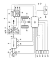
以下、本発明の実施形態を図面を参照して詳細に説明する。図1は本発明の実施形態に係る車両に搭載された自動変速機及びその制御装置の構成を示す図であり、内燃エンジン2のクランク軸4には自動変速機6が接続されている。
Hereinafter, embodiments of the present invention will be described in detail with reference to the drawings. FIG. 1 is a diagram showing a configuration of an automatic transmission mounted on a vehicle according to an embodiment of the present invention and a control device for the automatic transmission, and an
自動変速機6は、クランク軸4に連結され、ポンプインペラ8a及びタービンランナ8bを有するトルクコンバータ8と、ポンプインペラ8aとタービンランナ8bと連結するためのロックアップクラッチ10と、トルクコンバータ8の出力側に連結される多段変速ギヤ機構12と、ロックアップクラッチ10及び多段変速ギヤ機構12の動作を制御する油圧制御機構14とを備えている。
The
油圧制御機構14は、ロックアップクラッチ10の係合/非係合を切り替えるオンオフ型のソレノイド弁(以下「Aソレノイド弁」という)14aと、Aソレノイド弁14aがオンされ、ロックアップクラッチ10が係合状態にあるときの係合圧を制御するリニアソレノイド弁(以下「Bソレノイド弁」という)14bと、ギヤ機構12のシフト位置(ギヤ比)を制御する変速アクチュエータ14cとを含んでいる。
The
Aソレノイド弁14a,Bソレノイド弁14b及び変速アクチュエータ14cは、自動変速機制御用の電子コントロールユニット(以下「ECU」という)16に接続されており、ECU16はAソレノイド弁14a及びBソレノイド弁14bを介してロックアップクラッチ10の係合状態の制御を行うと共に、変速アクチュエータ14cを介して多段変速ギヤ機構12のシフト位置の制御を行う。
The
自動変速機6には、多段変速ギヤ12のシフト位置SRTDGを検出するシフト位置センサ18が設けられており、その検出信号はECU16に供給される。
The
エンジン2の出力は、クランク軸4からトルクコンバータ8、ギヤ機構12、差動装置20を順次経て、左右の駆動輪22,24に伝達され、これらを駆動する。また、自動変速機6の出力側には、当該車両の車速VPを検出する車速センサ26が設けられており、その検出信号はECU16に供給される。
The output of the
エンジン2には、吸気管28の途中に設けられたスロットル弁30の開度θTHを検出するスロットル弁開度センサ32と、エンジン冷却水温TWを検出するエンジン水温センサ34と、エンジン回転数NEを検出するエンジン回転数センサ36が設けられており、これらのセンサの検出信号はECU16に供給される。エンジン回転数センサ36は、クランク軸4の180度回転毎に所定クランク角度位置でTDC信号パルスを出力し、ECU16に供給する。
The
また、スロットル弁30には例えば電動モータからなるスロットルアクチュエータ38が連結されており、このスロットルアクチュエータ38はECU16に接続されている。ECU16には、車両のアクセルペダルの踏み込み量(以下「アクセル開度」という)APFZを検出するアクセル開度センサ40が接続されており、その検出信号がECU16に供給される。
Further, a
ECU16はアクセル開度APFZ等に応じて、スロットル弁開度θTHを制御する。即ち、本実施形態ではアクセルペダルとスロットル弁30とは機械的に連結されておらず、アクセル開度AP及び他の運転状態に応じてスロットル弁開度θTHが制御される。
The
ECU16には更に、自動変速機6の動作モードを選択するための選択レバー位置を検出する選択レバー位置センサ42、ブレーキペダルの踏み込みを検出するブレーキスイッチ44、操舵輪の舵角を検出する舵角センサ46及びヨーレイトセンサ48が接続されており、それらの検出信号はECU16に供給される。
The ECU 16 further includes a selection
ECU16には更にナビゲーション装置50が接続されている。ナビゲーション装置50は、GPSを利用して人工衛星からの電波(GPS信号)をアンテナ52を介して受信して現在位置を算出しつつ、予め記憶した地図内の道路上に車両の現在位置を表示させるとともに、車両の周辺道路例えば車両の進行方向の道路のコーナーの曲率半径Rや旋回角θを判定し、道路形状に則した制御信号を出力する。
A
尚、ECU16は、エンジン2に供給する燃料量(燃料噴射弁の開弁時間)及び点火時期等を制御する図示しないエンジン制御用電子コントロールユニットに接続されており、制御パラメータ情報を相互に伝達するように構成されている。 The ECU 16 is connected to an engine control electronic control unit (not shown) that controls the amount of fuel supplied to the engine 2 (opening time of the fuel injection valve), ignition timing, and the like, and transmits control parameter information to each other. It is configured as follows.
ECU16は、上述した各種センサからの入力信号波形を整形して電圧レベルを所定レベルに修正し、アナログ信号値をデジタル信号値に変換する等の機能を有する入力回路と、中央処理回路(CPU)と、CPUで実行される各種演算プログラムや後述するシフトマップ及び演算結果等を記憶するROM及びRAMからなる記憶回路と、Aソレノイド弁14a、Bソレノイド弁14b及び変速アクチュエータ14cに駆動信号を出力する出力回路とを備えている。
The
ECU16は、各種センサの検出信号に基づいてロックアップクラッチ10の係合状態、シフト位置及びスロットル弁開度θTHの制御を行う。尚、以下にフローチャートを参照して説明する処理は、ECU16のCPUで実行されるものであり、シフトマップはECU16のROMに記憶されているものである。
The
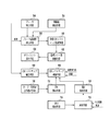
図2を参照すると、本発明にかかる自動変速機の制御装置の原理ブロック図が示されている。本発明の自動変速機の制御装置は、予め記憶されている通常シフトマップ及び複数のCSシフトマップ(コーナリングスポーツシフトマップ)に基づいて自動変速機の変速段を制御する。 Referring to FIG. 2, there is shown a principle block diagram of a control device for an automatic transmission according to the present invention. The control device for an automatic transmission according to the present invention controls a shift stage of the automatic transmission based on a normal shift map and a plurality of CS shift maps (cornering sport shift maps) stored in advance.
自動変速機の制御装置は、ブレーキのオン・オフを検出するブレーキ検出手段54及び直線路を検出する直線路検出手段56を含んでいる。ブレーキ検出手段54は、例えばブレーキスイッチ44から構成される。直線路であることは、例えばナビゲーション装置50からの情報により判断される。或いは、舵角又はヨーレイト等の車両情報から判断される。
The control device for the automatic transmission includes a brake detection means 54 for detecting on / off of the brake and a straight road detection means 56 for detecting a straight road. The brake detection means 54 is comprised from the
ブレーキ検出手段54でブレーキオンが検出され且つ直線路検出手段56で直線路が検出されたとき、ブレーキ減速度検出手段58によりブレーキ作動による減速度を検出する。この減速度は単位時間当たりの車速の変化から検出される。
When the brake on is detected by the
この検出された減速度に応じて、目標CSシフトマップ選択手段60により目標CSシフトマップを選択する。そして、選択された目標CSシフトマップと車速に応じて目標シフト段検索手段62で目標シフト段を検索する。 A target CS shift map is selected by the target CS shift map selection means 60 in accordance with the detected deceleration. Then, the target shift stage search means 62 searches for the target shift stage according to the selected target CS shift map and the vehicle speed.
ダウンシフト実行手段64が目標シフト段に応じてダウンシフトを実行する。このダウンシフトは目標シフト段に向かって一段づつ順次実行する。 The downshift execution means 64 executes a downshift according to the target shift stage. This downshift is sequentially executed step by step toward the target shift step.
ダウンシフト実行手段64で実行されたシフト段から出力される実変速信号及び車速に応じて、CSシフトマップ検索手段66がCSシフトマップを検索する。そして、ブレーキ検出手段54でブレーキオフが検出されたとき、CSシフトマップ確定手段68により検索されたCSシフトマップを確定する。
The CS shift map search means 66 searches the CS shift map according to the actual shift signal and vehicle speed output from the shift stage executed by the downshift execution means 64. Then, when the brake off is detected by the
カーブ・交差点走行検出手段70により道路のカーブ又は交差点走行中であると検出されたとき、第1保持手段72により確定されたCSシフトマップをカーブ又は交差点走行中保持する。 When the curve / intersection traveling detection means 70 detects that the vehicle is traveling on a road curve or an intersection, the CS shift map determined by the first retaining means 72 is retained during the curve or intersection traveling.
出口検出手段74によりカーブ又は交差点の出口を検出し、演算手段76によりカーブ又は交差点の出口から次のカーブ入口までの所要時間を演算する。この演算は、ナビゲーション情報から得られる次のカーブ入口までの距離と車速に基づいて行われる。そして、演算された所要時間が所定の設定時間よりも小さい場合には、第2保持手段76により確定されたCSシフトマップを保持する。
The
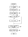
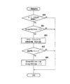
次に、図3以降のフローチャートを参照して、本発明の自動変速機の制御処理について説明する。図3は全体ジョブを示すフローチャートであり、本発明の制御はステップ10(図ではS10と記述する)のブレーキオンによるシフトダウン制御と、ステップ11のカーブホールド制御と、ステップ12の中間直線処理制御と、ステップ13の通常制御復帰処理から構成される。
Next, the control process of the automatic transmission according to the present invention will be described with reference to the flowcharts in FIG. FIG. 3 is a flowchart showing the entire job, and the control of the present invention is a shift down control by brake-on in step 10 (denoted as S10 in the figure), a curve hold control in step 11, and an intermediate straight line process control in
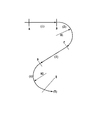
本発明の全体制御を図4のカーブ走行模式図を参照して簡単に説明する。 The overall control of the present invention will be briefly described with reference to the curve travel schematic diagram of FIG.
(1) まず区間A〜Bの直線減速部では、直線路であることをナビゲーション情報又は舵角、ヨーレイト等の車両情報から検出する。そして、カーブ進入前のブレーキ作動による減速度に応じて目標とするCSシフトマップを選択する。 (1) First, in the linear deceleration part of section A-B, it detects from a vehicle information, such as navigation information or a steering angle, a yaw rate, that it is a straight road. Then, a target CS shift map is selected according to the deceleration due to the brake operation before entering the curve.
この目標CSシフトマップと車速に応じて目標シフトダウンを設定し、ブレーキを踏んで減速している間、目標シフト段に向かって一段づつ順次シフトダウンを実行する。 The target shift down is set according to the target CS shift map and the vehicle speed, and while stepping on the brake and decelerating, the downshift is sequentially performed step by step toward the target shift step.
シフトダウンされた自動変速機からの実変速信号と車速に応じてCSシフトマップを検索し、ブレーキオフが検出されたとき検索されたCSシフトマップをFIXする(確定する)。 A CS shift map is searched in accordance with the actual shift signal from the downshifted automatic transmission and the vehicle speed, and when the brake-off is detected, the searched CS shift map is FIXed (determined).
(2) 区間B〜Cのカーブ走行中は、確定したCSシフトマップをホールドする。カーブであることは、ナビゲーション情報又は車両情報から検出する。エンジンブレーキ減速用のCSシフトマップをカーブ走行中も使用することで、カーブ走行中のアクセルペダル踏み込みによるダウンシフトを防止する。ただし、車速変化に対しては変速を許可する。 (2) Hold the confirmed CS shift map during the curve travel in the sections B to C. A curve is detected from navigation information or vehicle information. By using the CS shift map for engine brake deceleration while driving on a curve, downshifts caused by depressing the accelerator pedal while driving on a curve are prevented. However, shifting is permitted for changes in vehicle speed.
(3) 区間C〜Dのカーブとカーブの間の直線部においては、D点までの通過時間の予測によって制御をそのまま延長し、確定したCSシフトマップをホールドする。通過時間はC点からD点までのナビゲーション装置からの距離情報と車速から算出する。 (3) In the straight part between the curves of the sections C to D, the control is extended as it is by predicting the passing time to the point D, and the confirmed CS shift map is held. The passing time is calculated from the distance information from the navigation device from point C to point D and the vehicle speed.
(4) 区間D点〜E点までの2個目のカーブを走行中は、確定したCSシフトマップをホールドした状態でカーブへ進入する場合、B〜C間と同様な制御を行う。 (4) While traveling on the second curve from the section D point to the point E, when entering the curve while holding the confirmed CS shift map, the same control as between B to C is performed.
(5) E点以降のカーブ脱出時には、カーブ終了状態を検出してCSシフトマップから通常シフトマップに持ち替える。通常シフトマップへの復帰時には、登坂シフトマップ(軽登坂シフトマップ)に一度切り替えた後勾配を判断し、通常シフトマップに復帰することで、シフトマップが移行した際の駆動力段差の急変を防止する。 (5) When exiting the curve after point E, the end state of the curve is detected and the CS shift map is switched to the normal shift map. When returning to the normal shift map, after switching to the uphill shift map (light uphill shift map), the gradient is judged and then returned to the normal shift map to prevent sudden changes in the driving force step when the shift map is shifted. To do.
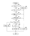
次に、図5のフローチャートを参照して、ブレーキ踏み込みによるダウンシフト処理について説明する。まず、ステップ20でブレーキオンか否かを検出し、ブレーキオンの場合には、ステップ21へ進んで下限車速V以上か否かを判断する。この下限車速Vは約20km/h〜30km/hに設定する。
Next, the downshift process by stepping on the brake will be described with reference to the flowchart of FIG. First, at
次いで、ステップ22へ進んでナビゲーション装置50からの情報により直線路を走行中か否かを判定する。直線路を走行中と判定された場合には、ステップ23へ進んで左右輪差回転、舵角、またはヨーレイトが一定以下か否かを判定する。このステップ23は車両情報から直線路か否かを判定するステップであり、ステップ22の判定をステップ23で再確認している。
Next, the routine proceeds to step 22 where it is determined whether or not the vehicle is traveling on a straight road based on information from the
ステップ23の判定が肯定判定の場合には、ステップ24へ進んでブレーキタイマーが0か否かを判定する。このブレーキタイマーは減算タイマーであり、ステップ28で例えば0.5秒にセットされる。
If the determination in
ステップ24が肯定判定の場合には、ステップ25でCSフラグを立て、ステップ26に進んでシフトマップの選択処理を実行する。ステップ24でブレーキタイマーが0でないと判定された場合には、ステップ27でブレーキタイマーの減算を実行する。
If the determination in
ステップ26のシフトマップ選択処理について、図6のフローチャートを参照して詳細に説明する。
The shift map selection process of
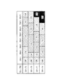
まず、ステップ30でブレーキ減速度を検出する。このブレーキ減速度は単位時間当たりの車速変化から検出する。次いで、ステップ31へ進んで減速度に応じた目標CSシフトマップを選択する。減速度に応じた目標CSシフトマップ選択表が表1に示されている。
First, at
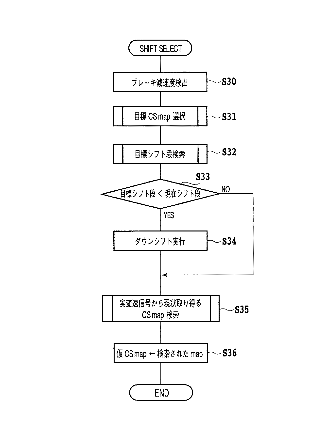
表1で、CSシフトマップはCS1,CS2,CS3の3種類からなり、番号が増えるにつれてより高い車速で低速ギヤを選択するシフトマップである。また、CS0は通常走行で選択しているシフトマップである。 In Table 1, the CS shift map is composed of three types of CS1, CS2, and CS3, and is a shift map that selects a low-speed gear at a higher vehicle speed as the number increases. Further, CS0 is a shift map that is selected during normal driving.
表1から明らかなように、減速度が小さく0.2G以下の場合には、車速の大小に係らずCS0を選択しているが、減速度が大きくなるにつれて高車速でより低速段を選択するCSシフトマップを選択するようになっている。 As is clear from Table 1, when the deceleration is small and 0.2 G or less, CS0 is selected regardless of the vehicle speed, but as the deceleration increases, the lower speed stage is selected at a higher vehicle speed. The CS shift map is selected.
次いで、ステップ32へ進んで選択された目標CSシフトマップと車速に応じて目標シフト段を検索する。選択された目標CSシフトマップと目標シフト段との関係は図8に示されている。 Next, the routine proceeds to step 32 where the target shift stage is searched according to the selected target CS shift map and the vehicle speed. The relationship between the selected target CS shift map and the target shift stage is shown in FIG.
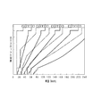
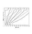
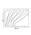
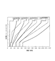
図9は車速とスロットル開度に応じた通常シフトマップを示している。実線がアップシフトを示し、1点鎖線がダウンシフトを示している。図10はCSシフトマップ1、図11はCSシフトマップ2、図12はCSシフトマップ3をそれぞれ示している。図9に示した通常シフトマップと同様に、実線がアップシフト、1点鎖線がダウンシフトを示している。
FIG. 9 shows a normal shift map according to the vehicle speed and the throttle opening. A solid line indicates an upshift, and a one-dot chain line indicates a downshift. 10 shows the
図6のフローチャートを再び参照すると、ステップ32の目標シフト段検索後、ステップ33へ進んで自動変速機の現在のシフト段が目標シフト段より大きいか否かを判定し、大きいと判定された場合にはステップ34へ進んでダウンシフトを実行する。すなわち、本実施形態では、ブレーキを踏んで減速している間、目標シフト段に向かって一段づつ順次シフトダウンを実行する。
Referring again to the flowchart of FIG. 6, after searching for the target shift stage in
ステップ35では、シフトダウンされた現在のシフト段(ギヤ位置)からの実変速信号と車速から図8を参照して現在とり得るCSシフトマップを検索する。検索されたCSシフトマップを、ステップ36で仮CSシフトマップとする。以上でCSシフトマップ選択処理が終了する。
In step 35, a currently available CS shift map is retrieved from the actual shift signal and the vehicle speed from the currently shifted gear position (gear position) with reference to FIG. The retrieved CS shift map is set as a temporary CS shift map in
再び図5のフローチャートを参照すると、ステップ20でブレーキオフと判定された場合、ステップ28へ進んでブレーキタイマーを例えば0.5秒にセットし、ステップ29へ進んで仮CSシフトマップをFIXする(確定する)。ステップ21、ステップ22及びステップ23の判定が否定判定の場合にも、ステップ29へ進んで仮CSシフトマップを確定する。
Referring to the flowchart of FIG. 5 again, if it is determined in
このCSシフトマップ確定処理を図7のフローチャートを参照して説明する。まず、ステップ40でブレーキオフか否かを判定し、ブレーキオフと判定された場合にはステップ41へ進んでCSフラグが立っているか否かを判定する。
This CS shift map determination process will be described with reference to the flowchart of FIG. First, it is determined in
ステップ41が肯定判定の場合には、ステップ42へ進んで仮CSシフトマップを確定CSシフトマップとする。そして、ステップ43でCSシフトマップFIXタイマー1をセットし、ステップ44でCS HOLDカウンターをセットする。
If step 41 is affirmative, the routine proceeds to step 42, where the temporary CS shift map is set as the confirmed CS shift map. In
CSシフトマップFIXタイマー1は、CSシフトマップがFIXされてからカーブに進入するまでCSシフトマップをホールドするためのタイマーである。2秒〜5秒程度に設定する。
The CS shift
この設定時間が短すぎると、ブレーキを解放してカーブに入るまでに通常制御に戻ってしまう。逆に長すぎると、車両前方がカーブでなく、シフトマップをホールドする必要がない状況で違和感が発生する。 If this set time is too short, normal control will be resumed before the brake is released and the curve is entered. On the other hand, if it is too long, the vehicle front is not a curve, and a sense of incongruity occurs in a situation where there is no need to hold the shift map.
CS HOLDカウンターはCS制御終了時に軽登坂マップを選択している時間を計時するものである。3秒〜5秒程度に設定する。 The CS HOLD counter measures the time during which the light uphill map is selected at the end of CS control. Set to about 3 to 5 seconds.
一方、ステップ40でブレーキがオンと判定された場合、またはステップ41でCSフラグが立っていないと判定された場合には、ステップ45に進んでCS0シフトマップ、即ち通常走行で選択しているシフトマップを確定シフトマップとする。
On the other hand, if it is determined in
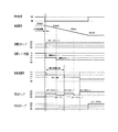
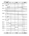
図13は80km/hから40km/hまでブレーキ減速したときのタイムチャートを示している。80km/hでブレーキ信号がオンとなり、ブレーキ減速度ΔVを検出して、車速と減速度に基づいて目標CSシフトマップとしてCSシフトマップ3を選択する。
FIG. 13 shows a time chart when the brake is decelerated from 80 km / h to 40 km / h. The brake signal is turned on at 80 km / h, the brake deceleration ΔV is detected, and the
この選択されたCSシフトマップ3と車速に応じて、目標シフト段(シフト位置)を検索する。この場合、車速条件等で最高段である6速からは2段シフトを許可している。よって、目標シフト段は車速に応じて4速、3速がセットされる。
A target shift stage (shift position) is searched according to the selected
ブレーキを踏んで減速している間、自動変速機はこの目標シフト段に向かって1段づつ順次シフトダウンを実行する。このシフトダウンに要する時間は自動変速機に依存する。自動変速機からはシフト位置を示す実変速信号が出力される。 While stepping on the brake and decelerating, the automatic transmission sequentially performs a downshift by one step toward the target shift step. The time required for this downshift depends on the automatic transmission. An actual transmission signal indicating the shift position is output from the automatic transmission.
よって、実変速信号と車速に応じて、図8のCSシフトマップを検索し、この検索したCSシフトマップを仮CSシフトマップとする。本実施形態では、仮CSシフトマップが、車速に応じてCSシフトマップ2、CSシフトマップ1、CSシフトマップ2、…と変化している。
Therefore, the CS shift map of FIG. 8 is searched according to the actual shift signal and the vehicle speed, and the searched CS shift map is set as a temporary CS shift map. In the present embodiment, the provisional CS shift map changes as
車速40km/hでブレーキがオフにされたため、このブレーキオフ信号に応じて車速40km/hでセットされていた仮CSシフトマップ3をCSシフトマップ3として確定する。
Since the brake is turned off at the vehicle speed of 40 km / h, the provisional
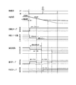
図14は図13に示したタイムチャートに対して、車速約55km/hでブレーキを解放した場合のフローチャートである。比較のため図13のタイムチャートの各信号は破線で示されている。 FIG. 14 is a flowchart when the brake is released at a vehicle speed of about 55 km / h with respect to the time chart shown in FIG. For comparison, each signal in the time chart of FIG. 13 is indicated by a broken line.
すなわち、この場合には、ブレーキオフ時に自動変速機は4速までしかシフトダウンされないため、4速の実変速信号と車速からブレーキオフ時にセットされていたCSシフトマップ2を確定CSシフトマップとする。
That is, in this case, since the automatic transmission is shifted down to only the fourth speed when the brake is off, the
図13のタイムチャートと図14のタイムチャートの比較から明らかなように、ブレーキが高い車速で解放された場合には、より段階の低いCSシフトマップが確定CSシフトマップとされる。 As is clear from the comparison between the time chart of FIG. 13 and the time chart of FIG. 14, when the brake is released at a high vehicle speed, the CS shift map at a lower stage is set as the confirmed CS shift map.
次に、図15のフローチャートを参照して、カーブ走行中確定されたCSシフトマップをホールドする処理について説明する。まず、ステップ50でCSシフトマップFIXタイマー1又は2が0か否かを判定する。
Next, with reference to the flowchart of FIG. 15, the process of holding the CS shift map determined during curve driving will be described. First, in
CSシフトマップFIXタイマー2は、CSシフトマップがFIXされてからカーブに進入するまでCSシフトマップをホールドするためのタイマーである。ナビ情報がある場合に次のカーブまでの到達時間を推定できるため、FIXタイマー2として別持ちとする。FIXタイマー2の設定時間はFIXタイマー1と同様な考え方でよく、先のカーブが特定できるため長めのタイマー設定が可能である。
The CS shift
肯定判定の場合には、ステップ51へ進んでカーブ又は交差点走行中か否かを判定する。このカーブ又は交差点走行中か否かの判定はナビゲーション装置50からの情報に基づいて判定する。
If the determination is affirmative, the routine proceeds to step 51 where it is determined whether the vehicle is traveling on a curve or an intersection. Whether the vehicle is traveling on a curve or an intersection is determined based on information from the
ステップ51でカーブ又は交差点走行中と判定された場合には、ステップ52へ進んで左右輪の差回転、又は舵角、又はヨーレイトが一定以上か否かを判定する。このステップ52は車両情報からカーブ又は交差点を走行中か否かを判定しているステップであり、ステップ51の判定を確認するステップである。
If it is determined in
ステップ52が肯定判定の場合には、ステップ53へ進んでCSシフトマップHOLDタイマー1をセットし、CSシフトマップHOLDタイマー2をリセットする。CSシフトマップHOLDタイマー1をセットしたことにより、このタイマーがリセットされるまでは図7のフローチャートのステップ42で確定されたCSシフトマップがホールドされる。
If
CSシフトマップHOLDタイマー1は、カーブ走行が終了し、一定時間CSシフトマップをホールドするためのタイマーである。2秒〜5秒程度に設定する。カーブ終了判断にばらつきが発生する場合を想定し、確実にカーブが終了してから通常制御に移行するための時間を確保するためのタイマーである。
The CS shift
CSシフトマップHOLDタイマー2は、カーブが終了し、一定時間CSシフトマップをホールドするためのタイマーである。ナビ情報からカーブ走行終了を判断した後のホールドタイマーとしてHOLDタイマー1とは別持ちである。1秒〜2秒程度に設定する。ナビ情報により、カーブ終了判断のばらつきが少ないと考えられるため短く設定する。
The CS shift
ステップ54では、CSシフトマップFIXタイマー1及びCSシフトマップFIXタイマー2のいずれもリセットし、本処理を終了する。
In
ステップ50の判定が否定判定の場合には、ステップ55へ進んでCSシフトマップHOLDタイマー2が0か否かを判定する。ステップ55の判定が肯定判定の場合には本処理を終了し、否定判定の場合には、ステップ51へ進んでカーブ又は交差点走行中か否かを判定する。
If the determination in
ステップ51でカーブ又は交差点走行中でないと判定された場合には、ステップ56に進んでナビゲーション装置50からの情報に基づいて、次のカーブ又は交差点開始点までの所要時間を演算する。
If it is determined in
ステップ57では、この演算された所要時間が設定時間より小さいか否かを判定し、肯定判定の場合にはステップ58へ進んでCSシフトマップFIXタイマー2をセットし、CSシフトマップFIXタイマー1をリセットする。ステップ57の判定が否定判定の場合には、本処理を終了する。
In
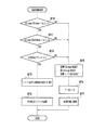
次に、図16のフローチャートを参照して、カーブとカーブの間の中間の直線路走行処理について説明する。まず、ステップ60でカーブ又は交差点出口通過後か否かを判定する。この判定はナビゲーション装置50からの情報に基づいて行う。
Next, with reference to the flowchart of FIG. 16, an intermediate straight road traveling process between curves will be described. First, in
ステップ60が肯定判定の場合には、ステップ61へ進んでCSシフトマップHOLDタイマ−1が0以外か否かを判定する。肯定判定の場合には、ステップ62へ進んで次のカーブ入口までの所要時間を演算する。この演算はナビゲーション装置50から得られた距離及び車速に基づいて行う。本実施形態では、次の交差点は除くものとする。
If
ステップ63では、演算された所要時間が設定時間より小さいか否かを判定し、肯定判定の場合にはステップ64へ進んでCSシフトマップHOLDタイマー2をセットし、CSシフトマップHOLDタイマー1を0にリセットする。
In step 63, it is determined whether or not the calculated required time is smaller than the set time. If the determination is affirmative, the routine proceeds to step 64 where the CS shift
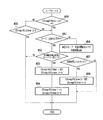
次に、図17のフローチャートを参照して、通常制御復帰処理について説明する。まず、ステップ70で、CSシフトマップFIXタイマー1及び2が0か否かを判定する。肯定判定の場合には、ステップ71へ進んでCSシフトマップHOLDタイマー1及び2が0か否かを判定する。ステップ71が肯定判定の場合には、ステップ72に進んでCS HOLDカウンターが0以外か否かを判定する。
Next, the normal control return processing will be described with reference to the flowchart of FIG. First, at
ステップ72が肯定判定の場合には、ステップ73に進んでシフトマップに軽登坂シフトマップをセットする。この軽登坂シフトマップの一例が図18に示されている。次いで、ステップ74に進んでCS HOLDカウンターを減算する。
If
一方、ステップ70、ステップ71、又はステップ72の判定が否定判定の場合には、ステップ75へ進んで目標CSシフトマップをリセットし、仮CSシフトマップをリセットし、目標シフト段をリセットする。次いで、ステップ76でCSフラグに0を代入し、ステップ77で通常制御に復帰する。
On the other hand, if the determination in
通常制御復帰時に、ステップ73でシフトマップに軽登坂シフトマップをセットしているのは、シフトマップが移行した際の駆動力段差の急変を防止するためである。 The reason why the light uphill shift map is set in the shift map in step 73 when returning to the normal control is to prevent a sudden change in the driving force step when the shift map is shifted.
図19は本制御全体のタイムチャートを示している。即ち、直線路から第1のカーブに進入し、中間直線路を進行して次のカーブに進入し、カーブが終了した直線路で本制御処理から抜け出るまでのタイムチャートである。 FIG. 19 shows a time chart of the entire control. That is, it is a time chart for entering the first curve from the straight road, proceeding through the intermediate straight road, entering the next curve, and exiting from the present control process on the straight road where the curve is completed.
2 エンジン
6 自動変速機
12 多段変速ギヤ機構
14 油圧制御機構
16 電子コントロールユニット(ECU)
26 車速センサ
32 スロットル弁開度センサ
36 エンジン回転数センサ
44 ブレーキスイッチ
46 舵角センサ
48 ヨーレイトセンサ
50 ナビゲーション装置
2
26
Claims (5)
ブレーキのオン・オフを検出するブレーキ検出手段と、
直線路を検出する直線路検出手段と、
前記ブレーキ検出手段でブレーキオンが検出され且つ前記直線路検出手段で直線路が検出されたとき、ブレーキ作動による減速度を検出するブレーキ減速度検出手段と、
前記減速度に応じて目標CSシフトマップを選択する目標CSシフトマップ選択手段と、
選択された目標CSシフトマップと車速に応じて目標シフト段を検索する目標シフト段検索手段と、
目標シフト段に応じてダウンシフトするダウンシフト実行手段と、
実変速信号と車速に応じてCSシフトマップを検索するCSシフトマップ検索手段と、
前記ブレーキ検出手段でブレーキオフが検出されたとき、前記検索されたCSシフトマップを確定するCSシフトマップ確定手段と、
を具備したことを特徴とする自動変速機の制御装置。 A control device for an automatic transmission that controls a shift stage of an automatic transmission based on a normal shift map and a plurality of CS shift maps stored in advance,
Brake detection means for detecting on / off of the brake;
Straight road detection means for detecting a straight road;
Brake deceleration detection means for detecting deceleration due to brake operation when brake on is detected by the brake detection means and a straight road is detected by the straight road detection means;
Target CS shift map selecting means for selecting a target CS shift map according to the deceleration;
A target shift stage search means for searching for a target shift stage according to the selected target CS shift map and the vehicle speed;
Downshift execution means for downshifting according to the target shift stage;
CS shift map search means for searching for a CS shift map according to the actual shift signal and the vehicle speed;
CS shift map determining means for determining the searched CS shift map when brake-off is detected by the brake detecting means;
A control device for an automatic transmission, comprising:
該カーブ・交差点走行検出手段により道路のカーブ又は交差点走行中であると検出されたとき、前記確定CSシフトマップをカーブ又は交差点走行中保持する第1保持手段とを更に具備したことを特徴とする請求項1記載の自動変速機の制御装置。 Curve / intersection driving detection means for detecting road curve or intersection driving;
And a first holding means for holding the fixed CS shift map during a curve or intersection traveling when the curve / intersection traveling detection means detects that the vehicle is traveling on a road curve or an intersection. The control device for an automatic transmission according to claim 1.
カーブ又は交差点の出口から次のカーブ入口までの所要時間を演算する演算手段と、
演算された所要時間が所定の設定時間よりも小さい場合には、前記確定されたCSシフトマップを保持する第2保持手段とを更に具備したことを特徴とする請求項2記載の自動変速機の制御装置。 Exit detection means for detecting a curve or intersection exit;
A calculation means for calculating the time required from the exit of the curve or intersection to the next curve entrance;
3. The automatic transmission according to claim 2, further comprising a second holding unit that holds the determined CS shift map when the calculated required time is smaller than a predetermined set time. Control device.
Priority Applications (1)
| Application Number | Priority Date | Filing Date | Title |
|---|---|---|---|
| JP2004120210A JP2005299879A (en) | 2004-04-15 | 2004-04-15 | Automatic transmission control device |
Applications Claiming Priority (1)
| Application Number | Priority Date | Filing Date | Title |
|---|---|---|---|
| JP2004120210A JP2005299879A (en) | 2004-04-15 | 2004-04-15 | Automatic transmission control device |
Publications (1)
| Publication Number | Publication Date |
|---|---|
| JP2005299879A true JP2005299879A (en) | 2005-10-27 |
Family
ID=35331643
Family Applications (1)
| Application Number | Title | Priority Date | Filing Date |
|---|---|---|---|
| JP2004120210A Withdrawn JP2005299879A (en) | 2004-04-15 | 2004-04-15 | Automatic transmission control device |
Country Status (1)
| Country | Link |
|---|---|
| JP (1) | JP2005299879A (en) |
Cited By (2)
| Publication number | Priority date | Publication date | Assignee | Title |
|---|---|---|---|---|
| DE112011102162T5 (en) | 2010-06-28 | 2013-05-16 | Honda Motor Co., Ltd. | Vehicle control unit and control method |
| DE102019126882A1 (en) | 2018-10-30 | 2020-04-30 | Toyota Jidosha Kabushiki Kaisha | SWITCHING CONTROL DEVICE FOR A VEHICLE |
-
2004
- 2004-04-15 JP JP2004120210A patent/JP2005299879A/en not_active Withdrawn
Cited By (4)
| Publication number | Priority date | Publication date | Assignee | Title |
|---|---|---|---|---|
| DE112011102162T5 (en) | 2010-06-28 | 2013-05-16 | Honda Motor Co., Ltd. | Vehicle control unit and control method |
| DE102019126882A1 (en) | 2018-10-30 | 2020-04-30 | Toyota Jidosha Kabushiki Kaisha | SWITCHING CONTROL DEVICE FOR A VEHICLE |
| US10890249B2 (en) | 2018-10-30 | 2021-01-12 | Toyota Jidosha Kabushiki Kaisha | Shift control device for vehicle |
| DE102019126882B4 (en) | 2018-10-30 | 2023-03-30 | Toyota Jidosha Kabushiki Kaisha | SHIFT CONTROL DEVICE FOR A VEHICLE |
Similar Documents
| Publication | Publication Date | Title |
|---|---|---|
| KR100582491B1 (en) | Deceleration control apparatus and method for a vehicle | |
| CN101462494B (en) | System for providing fuel-efficient driving information for vehicles | |
| US6970779B2 (en) | Vehicle speed control system and program | |
| JP6919315B2 (en) | Vehicle control unit | |
| JPH10141496A (en) | Vehicle control device | |
| JP2000065200A (en) | Control device for automatic transmission | |
| JP7506994B2 (en) | Control device and control method for vehicle equipped with automatic transmission | |
| JP4531876B2 (en) | Vehicle shift control device | |
| JP2018194043A (en) | Vehicle control device | |
| JP2000179676A (en) | Control device for automatic transmission | |
| WO2018207870A1 (en) | Vehicle control device | |
| JP6863064B2 (en) | Vehicle control unit | |
| JP4617915B2 (en) | Vehicle traveling path estimation device and vehicle deceleration control device | |
| JP2020008031A (en) | Control device of vehicle | |
| JP6881013B2 (en) | Vehicle control device | |
| JPH10299890A (en) | Vehicle control device | |
| WO2018207834A1 (en) | Vehicle control device and vehicle control method | |
| JP2000027981A (en) | Vehicle shift control device | |
| JP2005299879A (en) | Automatic transmission control device | |
| JP3955158B2 (en) | Control device for automatic transmission | |
| JP5034222B2 (en) | Vehicle driving force control device | |
| JP3913909B2 (en) | Control device for automatic transmission | |
| WO2018207869A1 (en) | Vehicle control device | |
| JP3913908B2 (en) | Control device for automatic transmission | |
| JP2001221339A (en) | Control device for automatic transmission |
Legal Events
| Date | Code | Title | Description |
|---|---|---|---|
| A300 | Withdrawal of application because of no request for examination |
Free format text: JAPANESE INTERMEDIATE CODE: A300 Effective date: 20070703 |