JP2005299853A - Exhaust pipe - Google Patents
Exhaust pipe Download PDFInfo
- Publication number
- JP2005299853A JP2005299853A JP2004119325A JP2004119325A JP2005299853A JP 2005299853 A JP2005299853 A JP 2005299853A JP 2004119325 A JP2004119325 A JP 2004119325A JP 2004119325 A JP2004119325 A JP 2004119325A JP 2005299853 A JP2005299853 A JP 2005299853A
- Authority
- JP
- Japan
- Prior art keywords
- exhaust pipe
- exhaust gas
- exhaust
- modification
- rectifying plate
- Prior art date
- Legal status (The legal status is an assumption and is not a legal conclusion. Google has not performed a legal analysis and makes no representation as to the accuracy of the status listed.)
- Granted
Links
Images


Classifications
-
- Y—GENERAL TAGGING OF NEW TECHNOLOGICAL DEVELOPMENTS; GENERAL TAGGING OF CROSS-SECTIONAL TECHNOLOGIES SPANNING OVER SEVERAL SECTIONS OF THE IPC; TECHNICAL SUBJECTS COVERED BY FORMER USPC CROSS-REFERENCE ART COLLECTIONS [XRACs] AND DIGESTS
- Y02—TECHNOLOGIES OR APPLICATIONS FOR MITIGATION OR ADAPTATION AGAINST CLIMATE CHANGE
- Y02E—REDUCTION OF GREENHOUSE GAS [GHG] EMISSIONS, RELATED TO ENERGY GENERATION, TRANSMISSION OR DISTRIBUTION
- Y02E60/00—Enabling technologies; Technologies with a potential or indirect contribution to GHG emissions mitigation
- Y02E60/30—Hydrogen technology
- Y02E60/50—Fuel cells
Landscapes
- Fuel Cell (AREA)
- Pipe Accessories (AREA)
- Rigid Pipes And Flexible Pipes (AREA)
Abstract
【課題】 本発明は排気管に関し、排気ガスの流通抵抗を増大させることなく、水分を含む排気ガスが大気中へ放出されたときの白煙の発生を抑制できるようにする。
【解決手段】 排気管2の内部に整流板4を配置する。整流板は、例えば排気ガスの流れ方向に螺旋状に形成したり、排気ガスの流れ方向に間隔をおいて複数配置したりしてもよい。
【選択図】 図1PROBLEM TO BE SOLVED: To suppress the generation of white smoke when exhaust gas containing moisture is released into the atmosphere without increasing the exhaust gas flow resistance.
A rectifying plate is disposed inside an exhaust pipe. For example, the rectifying plates may be formed in a spiral shape in the flow direction of the exhaust gas, or a plurality of rectifying plates may be arranged at intervals in the flow direction of the exhaust gas.
[Selection] Figure 1
Description
本発明は、水分(水蒸気や水滴)を含む排気ガスを大気中へ放出するための排気管に関する。 The present invention relates to an exhaust pipe for releasing exhaust gas containing moisture (water vapor or water droplets) into the atmosphere.
燃料電池は、アノードに水素を含む燃料ガスが接触しカソードに空気などの酸素を含む酸化ガスが接触することにより両電極で電気化学反応が起こり、起電力が発生する仕組みになっている。その際、カソードでは、アノード側から電解質膜を透過してきた水素イオンと酸素が反応して水が生成される。生成された水は水蒸気となり、カソードから排出されるオフガス(カソードオフガス)に含まれて大気中に放出される。 The fuel cell has a mechanism in which an electrochemical reaction occurs at both electrodes when a fuel gas containing hydrogen contacts the anode and an oxidizing gas containing oxygen such as air contacts the cathode, thereby generating an electromotive force. At that time, at the cathode, hydrogen ions that have permeated through the electrolyte membrane from the anode side react with oxygen to generate water. The generated water becomes water vapor and is contained in an off gas (cathode off gas) discharged from the cathode and released into the atmosphere.
通常、燃料電池は高温(例えば、比較的運転温度の低い固体高分子型燃料電池でも約80℃)で運転されているために、カソードオフガスの温度は大気温よりも高くなっている。このため、カソードオフガスが大気中へ放出された途端、急激な冷却によりカソードオフガスの温度は露点温度以下まで低下し、カソードオフガスに含まれる水蒸気が凝結して白煙が発生する。特に、大気温が低い冬季には白煙の発生は顕著になる。 Usually, since the fuel cell is operated at a high temperature (for example, about 80 ° C. even in a polymer electrolyte fuel cell having a relatively low operation temperature), the temperature of the cathode offgas is higher than the atmospheric temperature. For this reason, as soon as the cathode off gas is released into the atmosphere, the temperature of the cathode off gas is lowered to a dew point temperature or less due to rapid cooling, and water vapor contained in the cathode off gas is condensed to generate white smoke. In particular, white smoke is prominent in winter when the temperature is low.
白煙は外観上、また、それを見る者への心象においても好ましくない。特に、近年、燃料電池を搭載した電気自動車(燃料電池自動車)が開発されているが、燃料電池自動車を実用化する上で白煙についての対策は十分に検討される必要がある。多量の白煙は後続車両のドライバに不快感を与える可能性があるからである。また、白煙は燃料電池だけの問題ではなく、プラント等、他の分野においても問題になっている。 White smoke is undesirable in appearance and in the image of the viewer. In particular, in recent years, an electric vehicle (fuel cell vehicle) equipped with a fuel cell has been developed. However, measures for white smoke need to be fully studied in order to put the fuel cell vehicle into practical use. This is because a large amount of white smoke may cause discomfort to the driver of the following vehicle. In addition, white smoke is not only a problem for fuel cells, but also for other fields such as plants.
従来、白煙の発生を抑制する技術としては、例えば特許文献1に記載された技術が知られている。この従来技術は、プレクーリング工法による冷却コンクリートの製造時に発生する白煙を除去するための技術であり、排気管の内部に多数の邪魔板を櫛歯状に交互に配置している。排気ガスは排気管を流れる際に各邪魔板に衝突し、その際、排気ガスに含まれる水分が邪魔板に付着して除去されることで、白煙の大気中への放出が抑制される。
しかしながら、上記の従来技術では、邪魔板の設置によって排気管内の流通抵抗は極めて大きくなってしまう。排気管内の流通抵抗の増大は背圧を増大させ排気流量を減少させることになり、システムの運転性能の低下を招いてしまう。例えば、上記従来技術を燃料電池のカソードオフガスの排気管に適用した場合には、カソードへの酸素の供給が阻害され、燃料電池の発電性能は大きく低下してしまう。 However, in the above prior art, the flow resistance in the exhaust pipe becomes extremely large due to the installation of the baffle plate. An increase in the flow resistance in the exhaust pipe increases the back pressure and decreases the exhaust flow rate, leading to a decrease in the operating performance of the system. For example, when the above prior art is applied to the cathode offgas exhaust pipe of a fuel cell, the supply of oxygen to the cathode is hindered, and the power generation performance of the fuel cell is greatly reduced.
本発明は、上述のような課題を解決するためになされたもので、排気ガスの流通抵抗を増大させることなく、水分を含む排気ガスが大気中へ放出されたときの白煙の発生を抑制できるようにした排気管を提供することを目的とする。 The present invention has been made to solve the above-described problems, and suppresses the generation of white smoke when exhaust gas containing moisture is released into the atmosphere without increasing the flow resistance of the exhaust gas. An object of the present invention is to provide an exhaust pipe that can be made.
第1の発明は、上記の目的を達成するため、水分を含む排気ガスを大気中へ放出するための排気管であって、内部に整流板が配置されていることを特徴としている。 In order to achieve the above-mentioned object, the first invention is an exhaust pipe for discharging exhaust gas containing moisture into the atmosphere, and is characterized in that a rectifying plate is disposed inside.
第2の発明は、第1の発明において、前記整流板は前記排気ガスの流れ方向に螺旋状に形成されていることを特徴としている。 According to a second aspect, in the first aspect, the rectifying plate is formed in a spiral shape in the flow direction of the exhaust gas.
第3の発明は、第1又は第2の発明において、前記整流板は前記排気ガスの流れ方向に間隔をおいて複数配置されていることを特徴としている。 According to a third invention, in the first or second invention, a plurality of the rectifying plates are arranged at intervals in the flow direction of the exhaust gas.
第1の発明によれば、排気ガスに含まれる水蒸気は整流板との接触により熱を奪われて液化し整流板に付着する。また、水蒸気が排気ガス中で凝結してできた水滴も整流板との接触によって整流板に付着する。これにより、排気ガスに含まれる水分は排気管を通過することで排気ガス中から除去され、排気ガスが大気中へ放出されたときの白煙の発生は抑制される。また、整流板は排気ガスの流れを整流するものであるので、整流板の配置により排気管内の流通抵抗が大きく増大することはない。 According to the first invention, the water vapor contained in the exhaust gas is deprived of heat by contact with the rectifying plate and liquefies and adheres to the rectifying plate. Further, water droplets formed by condensing water vapor in the exhaust gas also adhere to the rectifying plate by contact with the rectifying plate. Thereby, the moisture contained in the exhaust gas is removed from the exhaust gas by passing through the exhaust pipe, and the generation of white smoke when the exhaust gas is released into the atmosphere is suppressed. Further, since the rectifying plate rectifies the flow of the exhaust gas, the flow resistance in the exhaust pipe does not increase greatly due to the arrangement of the rectifying plate.
第2の発明によれば、螺旋状に形成された整流板に沿って排気ガスが回転しながら流れることで、排気ガスに含まれる水滴には遠心力が作用する。この遠心力によって排気ガスからの水滴の分離が促進される。 According to the second aspect of the invention, the centrifugal force acts on the water droplets contained in the exhaust gas as the exhaust gas flows while rotating along the spirally rectifying plate. This centrifugal force promotes the separation of water droplets from the exhaust gas.
第3の発明によれば、整流板の設置部位と非設置部位とで排気ガスの流速に変化が生じる。これにより、流速が低下する部分において排気ガスからの水滴の分離が促進される。 According to the third aspect, the flow rate of the exhaust gas varies between the installation site and the non-installation site of the current plate. Thereby, separation of water droplets from the exhaust gas is promoted at a portion where the flow velocity is reduced.
実施の形態1.
以下、図1を参照して、本発明の実施の形態1について説明する。
本発明の排気管は、例えば車両に搭載される車両用燃料電池に適用することができる。
The first embodiment of the present invention will be described below with reference to FIG.
The exhaust pipe of the present invention can be applied to, for example, a vehicle fuel cell mounted on a vehicle.
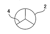
図1は、本発明の実施の形態1としての排気管の概略構成図である。本実施の形態の排気管2は、車両用燃料電池のカソードに接続され、カソードから排出される排気ガスを大気中へ放出するための排気管として構成されている。燃料電池では、電気化学反応によって起電力が発生する際、アノード側から電解質膜を透過してきた水素イオンと酸素が反応してカソードに水が生成される。燃料電池は高温で運転されるため生成された水は水蒸気となり、水蒸気はカソードから排出される排気ガスに含まれて排気管2へ排出される。
FIG. 1 is a schematic configuration diagram of an exhaust pipe as a first embodiment of the present invention. The
排気管2の内部には、排気ガスの流れを整流する整流板4が配置されている。整流板4は排気ガスの流れ方向に平行に、排気管2の内部を均等に4分割するように配置されている。排気ガスはこの整流板4の表面に沿って排気管2内を通過し、大気中へ放出される。
A rectifying
このように排気管2の内部に整流板4が配置されることで、排気ガスに含まれる水蒸気は排気管2内を通過する際に整流板4との接触により熱を奪われて液化し、水滴となって整流板4に付着する。また、水蒸気が排気ガス中で凝結してできた水滴も整流板4との接触によって整流板4に付着する。これにより排気ガスに含まれる水分(水蒸気及び水滴)の多くは排気ガス中から除去されることになり、排気ガスが大気中へ放出されたときの白煙の発生は抑制される。
By arranging the rectifying
また、整流板4は排気ガスの流れを整流するものであるので、邪魔板のように排気管2内の流通抵抗が大きく増大させてしまうことはない。したがって、整流板4が配置されることでカソードへの酸素の供給が阻害されることはなく、燃料電池の発電性能が低下してしまうこともない。
Further, since the rectifying
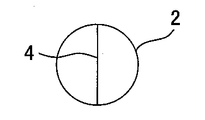
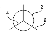
なお、図1では、排気管2の内部を均等に4分割するように整流板4を配置しているが、図2A,図2B,図2C,図2D,図2Eに示すような構成をとることもできる。図2Aに示す構成では、排気管2の内部を均等に8分割するように整流板4を配置している。図2Bに示す構成では、排気管2の内部を均等に3分割するように整流板4を配置している。図2Cに示す構成では、排気管2の内部を均等に2分割するように整流板4を配置している。また、図2Dに示す構成のように、排気管2の内部に整流板4を配置するとともに排気管2の外周面に放熱用のフィン6を設けてもよい。排気管2の熱をフィン6から放熱することで、整流板4による排気ガスの冷却効果を促進することができる。フィン6の形状や配置には限定はない。また、整流板4は平板に限定されず、図2Eに示す構成のように、整流板4を管状に形成することも可能である。
In FIG. 1, the
実施の形態2.
以下、図3を参照して、本発明の実施の形態2について説明する。
Hereinafter, the second embodiment of the present invention will be described with reference to FIG.
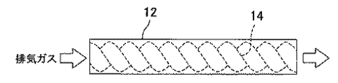
図3は、本発明の実施の形態2としての排気管の概略構成図である。本実施の形態の排気管12は、実施の形態1と同様、排気管12の内部に排気ガスの流れを整流する整流板14が配置されている。ただし、実施の形態1にかかる整流板4が排気ガスの流れ方向に平行に配置されているのに対し、本実施の形態にかかる整流板14は排気ガスの流れ方向に螺旋状(スパイラル状)に形成されている。
FIG. 3 is a schematic configuration diagram of an exhaust pipe as a second embodiment of the present invention. In the
このように整流板14が螺旋状に形成されることで、排気ガスは排気管12内を整流板14に沿って回転しながら流れることになる。このとき、排気ガスに含まれる水蒸気は整流板14との接触により熱を奪われて液化し、水滴となって整流板14に付着する。また、水蒸気が排気ガス中で凝結してできた水滴も整流板14との接触によって整流板14に付着する。螺旋状の整流板14は、実施の形態1にかかる整流板4のような平板状のものに比較して排気ガスとの接触面積が大きく、より効率的に排気ガス中の水分を除去することができる。
Thus, by forming the rectifying
さらに、螺旋状の整流板14によれば、排気ガスが回転しながら流れることで排気ガスに含まれる水滴には遠心力が作用することになり、この遠心力によって排気ガスからの水滴の分離が促進されるという効果もある。また、螺旋状の整流板14によっても排気ガスを乱れることなく流通させることができるので、排気管12内の流通抵抗を大きく増大させてしまうこともない。
Furthermore, according to the
なお、整流板14の枚数には限定はない。実施の形態1のように排気管12の内部をその断面内で4分割するように配置してもよく、より複数、或いは少数に分割するように配置してもよい。また、排気管12の外周面に放熱用のフィンを設けてもよい。
There is no limitation on the number of rectifying
実施の形態3.
以下、図4を参照して、本発明の実施の形態3について説明する。
Embodiment 3 FIG.
The third embodiment of the present invention will be described below with reference to FIG.
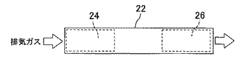
図4は、本発明の実施の形態3としての排気管の概略構成図である。本実施の形態の排気管22は、実施の形態1や実施の形態2と同様、排気管22の内部に排気ガスの流れを整流する整流板24,26が配置されている。ただし、先の実施の形態では、排気管の内部一箇所に整流板が配置されているのに対し、本実施の形態では、排気ガスの流れ方向に間隔をおいて2つの整流板24,26が配置されている。
FIG. 4 is a schematic configuration diagram of an exhaust pipe as a third embodiment of the present invention. In the
整流板24,26の設置箇所と非設置箇所とでは流路面積の違いにより排気ガスの流速が異なる。このため、間隔を開けて2つの整流板24,26が配置されることで排気ガスの流速には変化が生じ、整流板24と整流板26の間で排気ガスの流速は低下する。排気ガスの流速低下によって排気ガスに含まれる水滴は滴下を促され、排気ガスからの水滴の分離が促進される。
The flow rate of the exhaust gas differs depending on the flow path area between the installation location and the non-installation location of the rectifying
なお、各整流板24,26の構成には限定はない。実施の形態1にかかる整流板4の構成を適用してもよく、実施の形態1にかかる整流板14の構成を適用してもよい。また、上流の整流板24と下流の整流板26とで別々の構成を採用してもよい。また、図4では排気管22の内部に2つの整流板24,26を配置しているが、より多数の整流板を排気ガスの流れ方向に間隔をおいて配置してもよい。排気管22の外周面には放熱用のフィンを設けてもよい。
In addition, there is no limitation in the structure of each
その他.
以上、本発明の実施の形態について説明したが、本発明は上記実施の形態に限定されるものではなく、本発明の趣旨を逸脱しない範囲で種々変形して実施することができる。例えば、次のように変形して実施してもよい。
Others.
While the embodiments of the present invention have been described above, the present invention is not limited to the above-described embodiments, and various modifications can be made without departing from the spirit of the present invention. For example, the following modifications may be made.
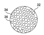
図5は、上記実施の形態の変形例1としての排気管の概略構成図である。本変形例では、排気管32の内部に整流壁34が設けられている。この整流壁34には多数の細孔36が形成されている。細孔36は排気ガスの流れ方向に平行に形成され、整流壁34の上流と下流とを連通させている。このような構成によれば、排気ガスに含まれる水分は細孔36を通過する際に細孔36の側壁に付着して排気ガス中から除去される。本変形例にかかる整流壁34は上記記実施の形態にかかる整流板の代わりに用いてもよく、或いは、整流板とともに用いてもよい。
FIG. 5 is a schematic configuration diagram of an exhaust pipe as a first modification of the above embodiment. In this modification, a rectifying
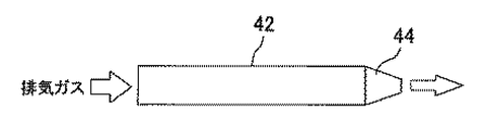
図6は、上記実施の形態の変形例2としての排気管の概略構成図である。本変形例は排気管42の出口部の構成に特徴がある。本変形例では、排気管42はその出口部にオリフィス44を備えている。排気管42から放出される排気ガスの流速は、排気管42の出口に生じる白煙の濃度に影響する。流速が小さいときには排気ガスが滞留することで白煙濃度は高まり、流速が大きいときには排気ガスが空気中に速やかに拡散されることで白煙濃度は低下する。本変形例によれば、排気ガスはオリフィス44を通過することでその流速が上昇し、大気中に速やかに拡散される。これにより、排気管42の出口に生じる白煙の濃度は低下して外部から白煙を視認しにくくなる。本変形例にかかる排気管42の構成を上記実施の形態の排気管2,12,22に適用することで、白煙の発生をより確実に抑制することが可能になる。
FIG. 6 is a schematic configuration diagram of an exhaust pipe as a second modification of the above embodiment. This modification is characterized by the configuration of the outlet portion of the
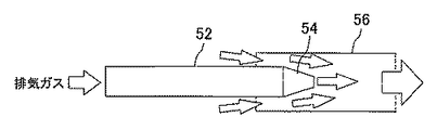
図7は、上記実施の形態の変形例3としての排気管の概略構成図である。本変形例も排気管52の出口部の構成に特徴がある。本変形例では、排気管52はその出口部にオリフィス54を備え、さらにその外側に筒状のバッフル56を備えている。本変形例によれば、排気ガスはオリフィス54を通過することでその流速が上昇する。排気ガスの流速の上昇により排気管52の出口における気圧は低下し、この圧力低下によりバッフル56と排気管52との隙間からバッフル56内に外気が取り込まれる。取り込まれた外気が排気ガスに混合することで排気ガスの露点は低下し、バッフル56の出口から大気中へ放出されたときの白煙の発生は抑制される。本変形例にかかる排気管52の構成を上記実施の形態の排気管2,12,22に適用することで、白煙の発生をより確実に抑制することが可能になる。
FIG. 7 is a schematic configuration diagram of an exhaust pipe as a third modification of the embodiment. This modification is also characterized by the configuration of the outlet portion of the
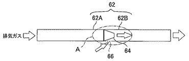
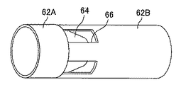
図8Aは、上記実施の形態の変形例4としての排気管の概略構成図である。図8Bは、図8Aの矢視A部を拡大して示す図である。本変形例では、排気管62は上流側排気管62Aと下流側排気管62Bとに分割されている。上流側排気管62Aはその出口部にオリフィス64を備えている。下流側排気管62Bはその入口部に複数の切り込み66を形成されている。上流側排気管62Aと下流側排気管62Bとはオリフィス64に切り込み66が重なるように接続されている。本変形例によれば、排気ガスはオリフィス64を通過することでその流速が上昇する。排気ガスの流速の上昇により流側排気管62Aの出口における気圧は低下し、この圧力低下により各切り込み66から下流側排気管62B内に外気が取り込まれる。取り込まれた外気が排気ガスに混合することで排気ガスの露点は低下し、下流側排気管62Bの出口から大気中へ放出されたときの白煙の発生は抑制される。本変形例にかかる排気管62の構成を上記実施の形態の排気管2,12,22に適用することで、白煙の発生をより確実に抑制することが可能になる。
FIG. 8A is a schematic configuration diagram of an exhaust pipe as a fourth modification of the embodiment. FIG. 8B is an enlarged view showing an arrow A part in FIG. 8A. In this modification, the
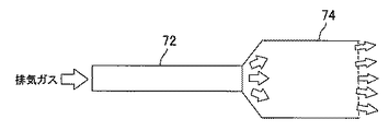
図9は、上記実施の形態の変形例5としての排気管の概略構成図である。本変形例は排気管72の出口部の構成に特徴がある。本変形例では、排気管72はその出口部に拡管74を備えている。拡管74は排気管72の本体部分よりも流路面積を格段に大きく形成されている。本変形例によれば、排気ガスは出口面積の広い拡管74から分散して放出されるので、排気ガス中の水滴を大気中に拡散させて白煙として認知されにくくすることができる。本変形例にかかる排気管72の構成を上記実施の形態の排気管2,12,22に適用することで、白煙の発生をより確実に抑制することが可能になる。
FIG. 9 is a schematic configuration diagram of an exhaust pipe as a fifth modification of the above embodiment. This modification is characterized by the configuration of the outlet portion of the
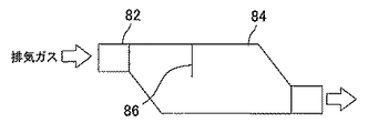
図10は、上記実施の形態の変形例6としての排気管の概略構成図である。本変形例では、排気管82はその出口部の近傍にバッファ84を備えている。バッファ84は排気管82の本体部分よりも流路面積を格段に大きく形成されている。また、バッファ84の出口は入口に対してずらして設けられている。また、バッファ84内には排気ガスの流れ方向に垂直に衝立86が設けられている。本変形例によれば、排気ガスが流路面積の広いバッファ84内を通過する際、排気ガスの流速は低下する。このとき、バッファ84の出口と入口とが同軸上にないことからバッファ84内では排気ガスの壁面への衝突が起き、また、途中に設けられた衝立86への排気ガスの衝突も起きる。その際、排気ガスに含まれる水分はバッファ84の内壁面や衝立86に付着して排気ガス中から除去される。さらに、排気ガスの流速低下によって排気ガスに含まれる水滴は滴下を促され、排気ガスからの水滴の分離が促進される。これにより、排気ガスに含まれる水分の多くは排気ガス中から除去されることになり、排気ガスが大気中へ放出されたときの白煙の発生は抑制される。本変形例にかかる排気管82の構成を上記実施の形態の排気管2,12,22に適用することで、白煙の発生をより確実に抑制することが可能になる。その際、整流板の下流にバッファを設けてもよく、上流にバッファを設けてもよい。或いは、バッファ内に整流板を設けてもよい。
FIG. 10 is a schematic configuration diagram of an exhaust pipe as a sixth modification of the embodiment. In this modification, the
図11は、上記実施の形態の変形例7としての排気管の概略構成図である。本変形例では、排気管92はその内部に電動ファン94を備えている。本変形例によれば、電動ファン94を回転させることで排気管92から放出される排気ガスの流速を高めることができ、排気ガスを大気中に速やかに拡散することができる。これにより、排気管92の出口に生じる白煙の濃度は低下して外部から白煙を視認しにくくなる。また、本変形例によれば、排気管92内の排気ガスを強制的に吸い出すことで、カソードへの酸素供給系の背圧を低下させることもできるという利点もある。本変形例にかかる排気管92の構成を上記実施の形態の排気管2,12,22に適用することで、白煙の発生をより確実に抑制することが可能になる。
FIG. 11 is a schematic configuration diagram of an exhaust pipe as Modification 7 of the above embodiment. In this modification, the
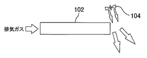
図12は、上記実施の形態の変形例8としての排気管の概略構成図である。本変形例では、排気管102はその外部であって出口の近傍に電動ファン104を備えている。電動ファン104はその送風方向を排気管102は出口に向けて配置されている。本変形例によれば、電動ファン102を回転させることで排気管102から放出される排気ガスを強制的に大気中に拡散させ、排気管102の出口に生じる白煙を外部から視認しにくくすることができる。本変形例にかかる排気管102の構成を上記実施の形態の排気管2,12,22に適用することで、白煙の発生をより確実に抑制することが可能になる。なお、ここでは排気ガスを強制的に拡散させる手段として電動ファン104を用いているが、他装置の排気ガスを誘導して排気管102の出口に吹き付けるようにしてもよい。
FIG. 12 is a schematic configuration diagram of an exhaust pipe as a modification 8 of the embodiment. In this modification, the
また、上記実施の形態では、車両用燃料電池においてカソードオフガスの排気時に発生する白煙を抑制するための手段として本発明を用いているが、本発明の用途はこれに限定されるものではない。例えば、燃料電池の場合、カソード側の水分の一部は電解質膜を透過してアノード側に漏れるため、アノードから排出されるアノードオフガスにも水蒸気が含まれている。或いは、炭化水素原料を改質して水素を得る燃料電池の場合、改質ガス中には水蒸気が含まれるため、アノードから排出されるアノードオフガスにも水蒸気が含まれている。このような場合においても本発明を適用することで、アノードオフガスを大気中へ放出するときの水蒸気白煙の発生を防止することが可能になる。その他、本発明は水分を含む排気ガスを大気中へ放出するための排気管であるならば、その用途を問わず広く適用することができる。 In the above-described embodiment, the present invention is used as means for suppressing white smoke generated during exhaust of cathode off gas in a vehicle fuel cell. However, the application of the present invention is not limited to this. . For example, in the case of a fuel cell, a part of the moisture on the cathode side permeates the electrolyte membrane and leaks to the anode side, so that the anode off-gas discharged from the anode also contains water vapor. Alternatively, in the case of a fuel cell in which hydrogen is obtained by reforming a hydrocarbon raw material, since the reformed gas contains water vapor, the anode off-gas discharged from the anode also contains water vapor. Even in such a case, by applying the present invention, it becomes possible to prevent generation of water vapor white smoke when the anode off-gas is discharged into the atmosphere. In addition, the present invention can be widely applied regardless of its use as long as it is an exhaust pipe for releasing exhaust gas containing moisture into the atmosphere.
2,12,22,32,42,52,62,72,82,92,102 排気管
4,14,24,26 整流板
6 フィン
34 整流壁
36 細孔
44,54,64 オリフィス
56 バッフル
66 切り込み
74 拡管
84 バッファ
86 衝立
94,104 電動ファン
2, 12, 22, 32, 42, 52, 62, 72, 82, 92, 102
Claims (3)
内部に整流板が配置されていることを特徴とする排気管。 An exhaust pipe for releasing exhaust gas containing moisture into the atmosphere,
An exhaust pipe having a rectifying plate disposed therein.
The exhaust pipe according to claim 1 or 2, wherein a plurality of the rectifying plates are arranged at intervals in the flow direction of the exhaust gas.
Priority Applications (1)
| Application Number | Priority Date | Filing Date | Title |
|---|---|---|---|
| JP2004119325A JP4568011B2 (en) | 2004-04-14 | 2004-04-14 | Exhaust pipe for fuel cell |
Applications Claiming Priority (1)
| Application Number | Priority Date | Filing Date | Title |
|---|---|---|---|
| JP2004119325A JP4568011B2 (en) | 2004-04-14 | 2004-04-14 | Exhaust pipe for fuel cell |
Publications (2)
| Publication Number | Publication Date |
|---|---|
| JP2005299853A true JP2005299853A (en) | 2005-10-27 |
| JP4568011B2 JP4568011B2 (en) | 2010-10-27 |
Family
ID=35331620
Family Applications (1)
| Application Number | Title | Priority Date | Filing Date |
|---|---|---|---|
| JP2004119325A Expired - Fee Related JP4568011B2 (en) | 2004-04-14 | 2004-04-14 | Exhaust pipe for fuel cell |
Country Status (1)
| Country | Link |
|---|---|
| JP (1) | JP4568011B2 (en) |
Cited By (4)
| Publication number | Priority date | Publication date | Assignee | Title |
|---|---|---|---|---|
| WO2009016492A3 (en) * | 2007-08-01 | 2009-05-22 | Toyota Motor Co Ltd | Exhaust state control device for fuel cell for mobile unit |
| JP2018085223A (en) * | 2016-11-24 | 2018-05-31 | トヨタ自動車株式会社 | Exhaust pipe structure |
| JP2019089442A (en) * | 2017-11-14 | 2019-06-13 | トヨタ自動車株式会社 | Exhaust pipe for fuel cell vehicle |
| JP2022098188A (en) * | 2020-12-21 | 2022-07-01 | 株式会社豊田自動織機 | Fuel cell unit |
Citations (1)
| Publication number | Priority date | Publication date | Assignee | Title |
|---|---|---|---|---|
| JPH09256845A (en) * | 1996-03-19 | 1997-09-30 | Michimasa Yamaguchi | Gas exhausting method for internal combustion engine |
-
2004
- 2004-04-14 JP JP2004119325A patent/JP4568011B2/en not_active Expired - Fee Related
Patent Citations (1)
| Publication number | Priority date | Publication date | Assignee | Title |
|---|---|---|---|---|
| JPH09256845A (en) * | 1996-03-19 | 1997-09-30 | Michimasa Yamaguchi | Gas exhausting method for internal combustion engine |
Cited By (6)
| Publication number | Priority date | Publication date | Assignee | Title |
|---|---|---|---|---|
| WO2009016492A3 (en) * | 2007-08-01 | 2009-05-22 | Toyota Motor Co Ltd | Exhaust state control device for fuel cell for mobile unit |
| US9531023B2 (en) | 2007-08-01 | 2016-12-27 | Toyota Jidosha Kabushiki Kaisha | Exhaust state control device for fuel cell for mobile unit |
| JP2018085223A (en) * | 2016-11-24 | 2018-05-31 | トヨタ自動車株式会社 | Exhaust pipe structure |
| JP2019089442A (en) * | 2017-11-14 | 2019-06-13 | トヨタ自動車株式会社 | Exhaust pipe for fuel cell vehicle |
| JP2022098188A (en) * | 2020-12-21 | 2022-07-01 | 株式会社豊田自動織機 | Fuel cell unit |
| JP7479692B2 (en) | 2020-12-21 | 2024-05-09 | 株式会社豊田自動織機 | Fuel Cell Unit |
Also Published As
| Publication number | Publication date |
|---|---|
| JP4568011B2 (en) | 2010-10-27 |
Similar Documents
| Publication | Publication Date | Title |
|---|---|---|
| US6472095B2 (en) | Hybrid fuel cell reactant flow fields | |
| CN108432011B (en) | Humidifier for fuel cell system with integrated dehydrator, fuel cell system and vehicle with such fuel cell system | |
| US8003278B2 (en) | Fuel cell | |
| JPH06267564A (en) | Solid high polymer electrolyte fuel cell | |
| US20060147774A1 (en) | Humidifier for fuel cell system | |
| US20170358804A1 (en) | Separator of fuel cell and fuel cell having the same | |
| JP2003523047A (en) | Refrigerant treatment system for direct antifreeze-cooled fuel cell assembly | |
| WO2012007998A1 (en) | Fuel cell | |
| US7691511B2 (en) | Fuel cell having coolant flow field wall | |
| JP5245315B2 (en) | Fuel cell | |
| JP5102574B2 (en) | Fuel cell system | |
| JP4672989B2 (en) | Fuel cell stack | |
| JP2005299853A (en) | Exhaust pipe | |
| JP2003523057A (en) | Fuel cell block | |
| JP5224646B2 (en) | Fuel cell separator | |
| JP2009048775A (en) | Fuel cell | |
| KR101976901B1 (en) | Unit cell of fuel cell | |
| JP7188323B2 (en) | Fuel cell separator and fuel cell | |
| JP2004259637A (en) | Fuel cell | |
| JP7028742B2 (en) | Fuel cell system | |
| JP2006236841A (en) | Fuel cell stack | |
| JP4453426B2 (en) | Fuel cell | |
| JP2005222897A (en) | Fuel cell system | |
| JP4939103B2 (en) | Fuel cell | |
| JP2003168468A (en) | Solid polymer type fuel cell |
Legal Events
| Date | Code | Title | Description |
|---|---|---|---|
| A621 | Written request for application examination |
Free format text: JAPANESE INTERMEDIATE CODE: A621 Effective date: 20070410 |
|
| A977 | Report on retrieval |
Free format text: JAPANESE INTERMEDIATE CODE: A971007 Effective date: 20090826 |
|
| A131 | Notification of reasons for refusal |
Free format text: JAPANESE INTERMEDIATE CODE: A131 Effective date: 20090908 |
|
| A521 | Request for written amendment filed |
Free format text: JAPANESE INTERMEDIATE CODE: A523 Effective date: 20091102 |
|
| A131 | Notification of reasons for refusal |
Free format text: JAPANESE INTERMEDIATE CODE: A131 Effective date: 20100518 |
|
| A521 | Request for written amendment filed |
Free format text: JAPANESE INTERMEDIATE CODE: A523 Effective date: 20100706 |
|
| TRDD | Decision of grant or rejection written | ||
| A01 | Written decision to grant a patent or to grant a registration (utility model) |
Free format text: JAPANESE INTERMEDIATE CODE: A01 Effective date: 20100803 |
|
| A01 | Written decision to grant a patent or to grant a registration (utility model) |
Free format text: JAPANESE INTERMEDIATE CODE: A01 |
|
| A61 | First payment of annual fees (during grant procedure) |
Free format text: JAPANESE INTERMEDIATE CODE: A61 Effective date: 20100806 |
|
| R151 | Written notification of patent or utility model registration |
Ref document number: 4568011 Country of ref document: JP Free format text: JAPANESE INTERMEDIATE CODE: R151 |
|
| FPAY | Renewal fee payment (event date is renewal date of database) |
Free format text: PAYMENT UNTIL: 20130813 Year of fee payment: 3 |
|
| R250 | Receipt of annual fees |
Free format text: JAPANESE INTERMEDIATE CODE: R250 |
|
| R250 | Receipt of annual fees |
Free format text: JAPANESE INTERMEDIATE CODE: R250 |
|
| R250 | Receipt of annual fees |
Free format text: JAPANESE INTERMEDIATE CODE: R250 |
|
| R250 | Receipt of annual fees |
Free format text: JAPANESE INTERMEDIATE CODE: R250 |
|
| R250 | Receipt of annual fees |
Free format text: JAPANESE INTERMEDIATE CODE: R250 |
|
| R250 | Receipt of annual fees |
Free format text: JAPANESE INTERMEDIATE CODE: R250 |
|
| R250 | Receipt of annual fees |
Free format text: JAPANESE INTERMEDIATE CODE: R250 |
|
| R250 | Receipt of annual fees |
Free format text: JAPANESE INTERMEDIATE CODE: R250 |
|
| R250 | Receipt of annual fees |
Free format text: JAPANESE INTERMEDIATE CODE: R250 |
|
| LAPS | Cancellation because of no payment of annual fees |