JP2005299842A - Pulley - Google Patents
Pulley Download PDFInfo
- Publication number
- JP2005299842A JP2005299842A JP2004119077A JP2004119077A JP2005299842A JP 2005299842 A JP2005299842 A JP 2005299842A JP 2004119077 A JP2004119077 A JP 2004119077A JP 2004119077 A JP2004119077 A JP 2004119077A JP 2005299842 A JP2005299842 A JP 2005299842A
- Authority
- JP
- Japan
- Prior art keywords
- pulley
- bearing
- fan
- boss
- rim
- Prior art date
- Legal status (The legal status is an assumption and is not a legal conclusion. Google has not performed a legal analysis and makes no representation as to the accuracy of the status listed.)
- Pending
Links
Images
Classifications
-
- F—MECHANICAL ENGINEERING; LIGHTING; HEATING; WEAPONS; BLASTING
- F16—ENGINEERING ELEMENTS AND UNITS; GENERAL MEASURES FOR PRODUCING AND MAINTAINING EFFECTIVE FUNCTIONING OF MACHINES OR INSTALLATIONS; THERMAL INSULATION IN GENERAL
- F16H—GEARING
- F16H57/00—General details of gearing
- F16H57/04—Features relating to lubrication or cooling or heating
- F16H57/0412—Cooling or heating; Control of temperature
- F16H57/0415—Air cooling or ventilation; Heat exchangers; Thermal insulations
Landscapes
- Engineering & Computer Science (AREA)
- General Engineering & Computer Science (AREA)
- Mechanical Engineering (AREA)
- Pulleys (AREA)
Abstract
【課題】プーリからの負荷を受ける軸受の冷却効果を高める。
【解決手段】回転軸6に結合されるボス2とベルトが巻き掛けられるリム3とを有するプーリ1において、ボス2とリム3とをスポーク4により連結するとともに、このスポーク4をファンの羽根として構成し、この羽根によりプーリ1に軸方向の送風を生じさせるようにする。プーリ1をファンに兼用して送風を発生させることにより、プーリ1からの負荷を受ける軸受8を効果的に冷却することができる。しかも、ファンの羽根はプーリ内部に構成されるためプーリ1の外形寸法を拡大することがなく、また羽根はスポーク4を兼用するため部品点数が増えることもない。
【選択図】 図1
A cooling effect of a bearing that receives a load from a pulley is enhanced.
In a pulley 1 having a boss 2 coupled to a rotating shaft 6 and a rim 3 around which a belt is wound, the boss 2 and the rim 3 are connected by a spoke 4, and the spoke 4 is used as a fan blade. The blades are configured so as to cause the pulley 1 to blow in the axial direction. By generating air by using the pulley 1 also as a fan, the bearing 8 that receives a load from the pulley 1 can be effectively cooled. In addition, since the fan blades are configured inside the pulley, the outer dimensions of the pulley 1 are not enlarged, and the blades also serve as the spokes 4, so that the number of parts does not increase.
[Selection] Figure 1
Description
この発明は、ベルト伝動用のプーリに関し、特に全閉外扇形モータに適したプーリに関する。 The present invention relates to a pulley for belt transmission, and more particularly to a pulley suitable for a fully closed outer fan motor.
機内の空気が外部と流通しない全閉形モータにおいては、一般に回転軸の反負荷側にファンを取り付け、このファンからの冷却風によりモータ外皮を冷却するようにしている(全閉外扇形モータ)。この全閉外扇形モータの負荷側には、軸端にしばしばプーリが結合され、このプーリに巻き掛けられたベルトを介して負荷の回転駆動が行われる。その場合、回転軸の負荷側軸受はベルトからの張力により大きな負荷力を受けろため軸受損失が大きくなり、軸受温度が上昇しやすい。そこで、従来はモータ外皮を通過させた冷却風の排風を負荷側軸受部に当てて冷却するようにしている。このような全閉外扇形モータについては、例えば特許文献1に記載されている。
ところが、上記した従来の軸受冷却はモータ外皮を冷却した後の排風を利用しているため冷却風の温度が高く、十分な冷却効果を得ることが困難であった。そこで、この発明の課題は、プーリからの負荷を受ける軸受の冷却効果を高めることにある。 However, the conventional bearing cooling described above uses exhaust air after cooling the motor skin, so that the temperature of the cooling air is high and it is difficult to obtain a sufficient cooling effect. Therefore, an object of the present invention is to enhance the cooling effect of a bearing that receives a load from a pulley.
上記課題を解決するために、この発明は、回転軸に結合されるボスとベルトが巻き掛けられるリムとを有するプーリにおいて、前記ボスとリムとをスポークにより連結するとともに、このスポークをファンの羽根として構成し、この羽根により軸方向に送風を生じさせるようにするものとする(請求項1)。 In order to solve the above-mentioned problems, the present invention provides a pulley having a boss coupled to a rotating shaft and a rim around which a belt is wound. The blade is configured to generate air in the axial direction (claim 1).
この発明は、プーリのボスとリムとを連結するスポークを軸方向に送風するファンの羽根として構成し、プーリに軸流ファンの機能を持たせるものである。このようにプーリをファンに兼用して送風を発生させることにより、プーリからの負荷を受ける軸受を新鮮な外気で効果的に冷却することができる。その場合、羽根はプーリ内部に構成されるためプーリの外形寸法を拡大させることがなく、またスポークを羽根として兼用するため部品点数が増えることもない。 According to the present invention, a spoke connecting the boss and rim of a pulley is configured as a fan blade for blowing air in the axial direction, and the pulley has a function of an axial fan. In this way, by generating air by using the pulley also as a fan, the bearing that receives the load from the pulley can be effectively cooled with fresh outside air. In that case, since the blade is configured inside the pulley, the outer dimension of the pulley is not enlarged, and the number of parts is not increased because the spoke is also used as the blade.
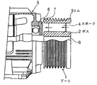
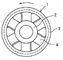
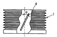
以下、図1〜図3に基づいて、全閉外扇形モータに用いられるプーリにおけるこの発明の実施の形態を示す。ここで、図1はプーリが取り付けられたモータ負荷側の要部を断面で示した側面図、図2は図1におけるプーリの右正面図、図3は図2の要部を破断した上面図である。図1〜図3において、プーリ1はVベルト用で、ボス2、リム3及びこれらを連結する複数(図示は6本)のスポーク4からなり、リム3には図示しないVベルトが巻き掛けられる複数のV溝が形成されている。図示の場合、プーリ1は全閉外扇形モータ5における回転軸6の負荷側端部に、ボス2を介して結合されている。
Hereinafter, based on FIGS. 1-3, embodiment of this invention in the pulley used for a fully-closed outer fan motor is shown. Here, FIG. 1 is a side view showing a cross section of a main part on the motor load side to which a pulley is attached, FIG. 2 is a right front view of the pulley in FIG. 1, and FIG. 3 is a top view in which the main part of FIG. It is. 1 to 3, the
ここで、プーリ1のボス2から放射状に伸びるスポーク4は、図3に示すように軸方向に対して角度θだけ傾斜し、軸方向に送風するファンの羽根として構成されている。そこで、プーリ1が図2の矢印方向に回転すると、図1の矢印方向に送風が発生し、プーリ1の反モータ側(図1におけるプーリ1の右側)の外気は冷却風として、モータ5の負荷側軸受箱7に吹き付けられる。その結果、軸受箱7は新鮮な外気で冷却され、軸受8の温度が低下するため、グリース寿命が大幅に延びて密封軸受の採用によるメンテナンスフリー化も可能になる。
Here, the
図示実施の形態では、全閉外扇形モータに用いられるプーリの例を示したが、この発明はプーリ一般に適用可能であり、プーリが取り付けられる軸を支持する軸受の冷却に効果がある。また、プーリによる送風は必ずしも軸受の冷却に限定されるものではなく、他の用途に振り向けることは自由である。更に、負荷を軸端に直結するカップリングにこの発明を応用し、カップリングにファン機能を持たせることも可能である。 In the illustrated embodiment, an example of a pulley used in a fully-enclosed external fan motor has been described. However, the present invention is applicable to a pulley in general and is effective in cooling a bearing that supports a shaft to which the pulley is attached. Further, the air blow by the pulley is not necessarily limited to cooling the bearing, and can be freely used for other purposes. Furthermore, the present invention can be applied to a coupling in which a load is directly connected to the shaft end, and the fan function can be given to the coupling.
1 プーリ
2 ボス
3 リム
4 スポーク
5 モータ
6 回転軸
7 軸受箱
8 軸受
1 Pulley 2 Boss 3 Rim 4 Spoke 5
Claims (1)
In a pulley having a boss coupled to a rotating shaft and a rim around which a belt is wound, the boss and the rim are connected by a spoke, and the spoke is configured as a fan blade, and air is blown in the axial direction by the blade. A pulley characterized by being generated.
Priority Applications (1)
| Application Number | Priority Date | Filing Date | Title |
|---|---|---|---|
| JP2004119077A JP2005299842A (en) | 2004-04-14 | 2004-04-14 | Pulley |
Applications Claiming Priority (1)
| Application Number | Priority Date | Filing Date | Title |
|---|---|---|---|
| JP2004119077A JP2005299842A (en) | 2004-04-14 | 2004-04-14 | Pulley |
Publications (1)
| Publication Number | Publication Date |
|---|---|
| JP2005299842A true JP2005299842A (en) | 2005-10-27 |
Family
ID=35331610
Family Applications (1)
| Application Number | Title | Priority Date | Filing Date |
|---|---|---|---|
| JP2004119077A Pending JP2005299842A (en) | 2004-04-14 | 2004-04-14 | Pulley |
Country Status (1)
| Country | Link |
|---|---|
| JP (1) | JP2005299842A (en) |
Cited By (5)
| Publication number | Priority date | Publication date | Assignee | Title |
|---|---|---|---|---|
| FR2914720A1 (en) * | 2007-04-04 | 2008-10-10 | Skf Ab | ROLLER OR ROLLER DEVICE |
| KR20160000090A (en) * | 2014-06-23 | 2016-01-04 | 동양물산기업 주식회사 | Tension pulley assembly having cooling function |
| DE102015118194A1 (en) * | 2015-10-26 | 2017-04-27 | Nsk Deutschland Gmbh | Pulley, traction drive and engine and motor vehicle |
| JP2019137315A (en) * | 2018-02-14 | 2019-08-22 | 株式会社丸山製作所 | vehicle |
| DE102021002614A1 (en) | 2020-06-05 | 2021-12-09 | Sew-Eurodrive Gmbh & Co Kg | Drive, in particular gear driven by an electric gate, with a shaft |
-
2004
- 2004-04-14 JP JP2004119077A patent/JP2005299842A/en active Pending
Cited By (7)
| Publication number | Priority date | Publication date | Assignee | Title |
|---|---|---|---|---|
| FR2914720A1 (en) * | 2007-04-04 | 2008-10-10 | Skf Ab | ROLLER OR ROLLER DEVICE |
| KR20160000090A (en) * | 2014-06-23 | 2016-01-04 | 동양물산기업 주식회사 | Tension pulley assembly having cooling function |
| KR101648258B1 (en) * | 2014-06-23 | 2016-08-16 | 동양물산기업 주식회사 | Tension pulley assembly having cooling function |
| DE102015118194A1 (en) * | 2015-10-26 | 2017-04-27 | Nsk Deutschland Gmbh | Pulley, traction drive and engine and motor vehicle |
| JP2019137315A (en) * | 2018-02-14 | 2019-08-22 | 株式会社丸山製作所 | vehicle |
| DE102021002614A1 (en) | 2020-06-05 | 2021-12-09 | Sew-Eurodrive Gmbh & Co Kg | Drive, in particular gear driven by an electric gate, with a shaft |
| WO2021244856A1 (en) | 2020-06-05 | 2021-12-09 | Sew-Eurodrive Gmbh & Co. Kg | A drive mechanism, in particular for a transmission driven by an electric motor, comprising a shaft |
Similar Documents
| Publication | Publication Date | Title |
|---|---|---|
| KR100720350B1 (en) | Fully-enclosed fan-cooled motor | |
| JP6444946B2 (en) | robot | |
| JP2016174529A (en) | Fan module | |
| US10205372B2 (en) | Motor-generator shaft with centrifugal fan blades | |
| JP2010098791A (en) | Totally enclosed rotary electric motor | |
| US8025546B2 (en) | Ducted fan assembly for radio-controlled model | |
| JP2002218704A (en) | Fully enclosed fan motor | |
| US7507068B2 (en) | Heat-dissipating mechanism for a motor | |
| KR20090108407A (en) | Automotive Cooling Fan Assembly | |
| US20140183990A1 (en) | Arrangement and method for cooling an electric machine | |
| JP2008029150A (en) | Fully closed motor | |
| KR100446783B1 (en) | Cooling fan for motor | |
| US6916149B2 (en) | Vortex blower | |
| JP2006207379A (en) | Blast fan | |
| AU2014322794A1 (en) | An electric or hybrid vehicle using motor-generator having shaft with centrifugal fan blades for cooling | |
| KR101644782B1 (en) | The handpiece | |
| JP2007318919A (en) | Fully enclosed motor for vehicles | |
| JP7573364B2 (en) | Cooling tower reduction gear | |
| KR950001030Y1 (en) | Ventilator of flanged general-purpose motor | |
| JP2003324894A (en) | Rotary drive | |
| CN223553148U (en) | A high-safety-performance motor rotor | |
| JP7145938B2 (en) | Electric motor | |
| JP6525313B2 (en) | motor | |
| KR102673279B1 (en) | Oil cooling type inwheel motor device | |
| JP3656665B2 (en) | Industrial robot arm drive cooling system |