JP2005299836A - Flow regulating valve - Google Patents
Flow regulating valve Download PDFInfo
- Publication number
- JP2005299836A JP2005299836A JP2004118510A JP2004118510A JP2005299836A JP 2005299836 A JP2005299836 A JP 2005299836A JP 2004118510 A JP2004118510 A JP 2004118510A JP 2004118510 A JP2004118510 A JP 2004118510A JP 2005299836 A JP2005299836 A JP 2005299836A
- Authority
- JP
- Japan
- Prior art keywords
- valve
- shaft
- valve body
- valve shaft
- valve stem
- Prior art date
- Legal status (The legal status is an assumption and is not a legal conclusion. Google has not performed a legal analysis and makes no representation as to the accuracy of the status listed.)
- Pending
Links
- 230000001105 regulatory effect Effects 0.000 title abstract 2
- 239000012530 fluid Substances 0.000 claims description 6
- 238000013459 approach Methods 0.000 claims description 2
- XLYOFNOQVPJJNP-UHFFFAOYSA-N water Substances O XLYOFNOQVPJJNP-UHFFFAOYSA-N 0.000 description 9
- 238000007789 sealing Methods 0.000 description 5
- 230000002093 peripheral effect Effects 0.000 description 4
- 238000010586 diagram Methods 0.000 description 3
- 230000007704 transition Effects 0.000 description 1
Images
Landscapes
- Details Of Valves (AREA)
- Lift Valve (AREA)
- Electrically Driven Valve-Operating Means (AREA)
Abstract
Description
本発明は、配管途中に設置され、モータの作動によって配管中の流量を調節する流量調節弁に関する。 The present invention relates to a flow rate control valve that is installed in the middle of piping and adjusts the flow rate in the piping by the operation of a motor.
従来のこの種の流量調節弁は、サーボモータの回転軸に対して、軸線方向に移動自在に係合した弁軸を備え、かつ弁軸の外周面にネジ部を設けると共に、ハウジングに固定されたナット部をこのネジ部に螺合させている。従って、サーボモータを回転駆動すると弁軸が回転する。この弁軸にはナット部が螺合しており、かつナット部は固定されているので弁軸は軸線方向に移動する。弁軸の先端には弁体が取り付けられており、弁体が弁座に近づくことにより流路が狭くなり流量が減少するように構成されている(例えば、特許文献1参照)。
上記弁軸の外周にはOリングがシール部材として取り付けられている。弁軸は上述のように回転しながら往復移動するのでこのシール部材に対して大きなストレスが作用する。そのためシール部材の耐久性が短くなる。シール部材でのシール性が低下すると水等の流体がサーボモータ側に漏出するので、頻繁にシール部材を交換しなければならない。 An O-ring is attached to the outer periphery of the valve shaft as a seal member. Since the valve shaft reciprocates while rotating as described above, a large stress acts on the seal member. Therefore, the durability of the seal member is shortened. Since the fluid such as water leaks to the servo motor side when the sealing performance of the sealing member is deteriorated, the sealing member must be frequently replaced.
そこで本発明は、上記の問題点に鑑み、弁軸に取り付けられたシール部材の寿命を長くすることのできる流量調節弁を提供することを課題とする。 Then, this invention makes it a subject to provide the flow control valve which can lengthen the lifetime of the sealing member attached to the valve stem in view of said problem.
上記課題を解決するために本発明による流量調節弁は、往復移動可能な弁軸に取り付けた弁体を、流体の流路途中に設けた弁座に対して往復移動させ、弁座と弁体との距離を変化させることにより流体の流量を調節をする流量調節弁であって、正逆回転可能なモータと、このモータの正逆回転力を弁軸の往復移動に変換するネジ機構とを備えたものにおいて、上記弁軸を囲繞するシール部材を備え、かつ、弁軸を回転させることなく往復移動方向にガイドする回り止め手段を設けると共に、上記ネジ機構の構成要素であるネジ部とナット部とのうちの一方を弁軸に設け、他方をモータの回転軸によって回転自在に設けたことを特徴とする。 In order to solve the above problems, a flow rate adjusting valve according to the present invention reciprocates a valve body attached to a valve shaft capable of reciprocating movement with respect to a valve seat provided in the middle of a fluid flow path. A flow control valve that adjusts the flow rate of the fluid by changing the distance between the motor and a motor that can rotate forward and backward, and a screw mechanism that converts the forward and reverse rotational force of the motor into a reciprocating movement of the valve shaft. And a screw member and a nut which are components of the screw mechanism, provided with a seal member that surrounds the valve shaft, and provided with a detent means for guiding the valve shaft in the reciprocating direction without rotating. One of the parts is provided on the valve shaft, and the other is provided rotatably by a rotating shaft of a motor.
ネジ機構はネジ部とナット部とで構成される。例えば弁軸にはネジ部を設けると共に回り止め手段を設け、ナット部側をモータで回転させるように構成したので、弁軸は回転することなく往復移動のみを行う。これにより弁軸にシール部材を取り付けても回転力がシール部材に作用しないのでシール部材に作用するストレスが従来のものより低減され、シール部材の摩耗が抑制される。なお、ナット部を弁軸に設けて、このナット部に螺合するネジ部をモータで回転するように構成してもよい。 The screw mechanism includes a screw portion and a nut portion. For example, since the valve shaft is provided with a screw portion and a rotation preventing means, and the nut portion side is rotated by a motor, the valve shaft does not rotate but only reciprocates. Thereby, even if the seal member is attached to the valve shaft, the rotational force does not act on the seal member, so that the stress acting on the seal member is reduced as compared with the conventional one, and the wear of the seal member is suppressed. Note that a nut portion may be provided on the valve shaft, and a screw portion screwed into the nut portion may be rotated by a motor.
上記弁体を弁軸に沿って摺動自在に設けると共に、弁体を弁座方向に付勢する付勢手段を弁体と弁軸との間に縮設してもよい。 While providing the said valve body so that sliding is possible along a valve axis | shaft, the urging | biasing means which urges | biases a valve body to a valve seat direction may be shrunk between a valve body and a valve shaft.
なお、上記付勢手段をバネとすれば、弁軸が弁体よりも相対的に弁座に近づくとバネが縮められ付勢力が増加するように設定できる。 If the urging means is a spring, it can be set so that the urging force increases when the valve shaft is closer to the valve seat than the valve body and the spring is contracted.
また、弁軸の弁座方向への移動距離が、弁体の弁座方向への移動距離より所定距離長くなると、弁軸と弁体とが相互に係合して上記付勢手段を介さず弁軸が弁体を直接弁座方向へ移動させる係合手段を設けてもよい。 Further, when the moving distance of the valve shaft in the valve seat direction is longer than the moving distance of the valve body in the valve seat direction by a predetermined distance, the valve shaft and the valve body are engaged with each other and do not go through the biasing means. The valve shaft may be provided with engagement means for moving the valve body directly in the valve seat direction.
以上の説明から明らかなように、本発明は、弁軸が往復移動する際に回転しないので弁軸にシール部材を取り付けてもシール部材の摩耗が少なくなり、このシール部材のシール不良による漏水が防止され、あるいはシール部材の交換スパンが長くなる。 As is clear from the above description, the present invention does not rotate when the valve shaft reciprocates, so even if a seal member is attached to the valve shaft, wear of the seal member is reduced, and water leakage due to a seal failure of this seal member is reduced. Is prevented, or the replacement span of the seal member is increased.
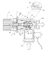
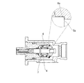
図1を参照して、1は本発明による流量調節弁であり、ケーシング12の左端の開口部にはブラケット板11が取り付けられている。このブラケット板11には正逆回転可能なサーボモータ2が取り付けられている。このサーボモータ2の回転軸21の内周面にはセレーションが形成されており、ナット部材3がそのセレーションに係合している。このナット部材3はブラケット板11に回転自在に係合している。したがって、回転軸21が正逆回転するとナット部材3も回転軸21と共に正逆回転する。
Referring to FIG. 1, reference numeral 1 denotes a flow control valve according to the present invention, and a
このナット部材3には雌ネジ部31が形成されており、弁軸5の一端部に形成されたネジ部51がこの雌ねじ部31に螺合している。ケーシング12内には保持部材4が固定されており、上記弁軸5はこの保持部材4に往復移動自在に保持されている。なお、弁軸5の中央部分にはOリングからなるシール部材52が取り付けられている。また、弁軸5の他端部には弁体6が取り付けられている。弁軸5の他端部にはストッパ部54が形成されており、この弁体6はストッパ部54に当接して弁軸5から抜けないように構成されている。ただし、弁体6は弁軸5に沿って摺動自在に保持されており、かつ弁軸5と弁体6との間にはバネ7が縮設され、弁体6はこのバネ7によってストッパ部54に対し所定の大きさの付勢力によって押接されている。弁体6には弁座13に当接して流路を閉塞するための弁シール61と、保持部材4との間でのシールを行うOリングであるシール部材62とが巻着されている。
The
図1に示すように、バネ7によって弁体6がストッパ部54に押接されている状態では所定の距離を介して対峙するように係合部5a,6aが各々弁軸5および弁体6に形成されている。
As shown in FIG. 1, when the
この流量調節弁1は配管途中に取り付けられ、例えば流体として水配管の場合、流入口1inから流入する水を流出口1outから流出させるものである。そして、水の流路途中に位置する弁座13に対して弁体6の弁シール61を近づけ、あるいは遠ざけることによって流出口1outから流出する水の流量を調節するものである。なお、実際の流量は流量計8によって検出される。
This flow control valve 1 is attached in the middle of the piping. For example, in the case of a water piping as a fluid, the water flowing in from the inflow port 1in is flowed out from the outflow port 1out. The flow rate of water flowing out from the outlet 1out is adjusted by bringing the
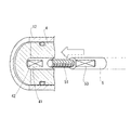
図2を参照して、保持部材4の中央には弁軸5が挿通されるガイド穴41が形成されており、弁軸5はこのガイド穴41にガイドされて往復移動することができる。そして更に、ガイド穴41の内周面には回り止めガイド42が突設されており、弁軸5の外周面にはこの回り止めガイドと対峙する平面部53が形成されている。したがって、ガイド穴41に挿通された状態の弁軸5は回転することなく図において左右方向に往復移動自在に保持されることになる。
With reference to FIG. 2, a
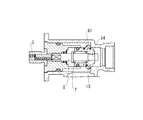
図1に示す状態は、開度が全開の状態を示している。この状態からサーボモータ2を正転させ、図3に示すように、弁体6の取り付けられている弁シール61が弁座13に当接した状態が止水状態である。ただし、この時点ではバネ7による付勢力はストッパ部54が受けており、弁シール61は弁座13に単に接触しているだけである。
The state shown in FIG. 1 shows a state where the opening degree is fully open. From this state, the
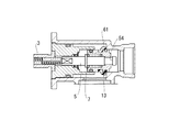
この止水状態からサーボモータ2をさらに正転させると、図4に示すように、弁軸5は図において右方向にさらに移動する。ところが、弁体6は弁シール61が弁座13に当接しているため右方向に移動することができず、止水状態のままで留まる。すると、ストッパ部54から弁体6が離れて、バネ7の付勢力は弁シール61を介して弁座13に作用する。すなわち、バネ7の付勢力によって弁シール61が弁座13に押接される。この状態を全閉状態とする。止水状態からこの全閉状態に移行する間にバネ7は若干であるが圧縮されるのでバネ7の付勢力は若干増加することになる。
When the
ところで、上記図1に示した全開状態から弁軸5を閉弁方向に移動させる際に、弁体6が保持部材4に引っ掛かって、弁軸5のみが閉弁方向に移動し、弁体6が移動しない不具合が生じるおそれがある。
By the way, when the
このような場合には、バネ7が圧縮されて弁体6を閉弁方向に付勢する付勢力が増加する。そのため保持部材4に対する引っかかりが外れやすくなる。ところが、付勢力の増加だけでは保持部材4に対する引っかかりが解消されない場合には、図5に示すように、係合部5a,6aが相互に当接し、サーボモータ2から弁軸5に対する推力がバネ7を介することなく直接弁体6に作用し、大きな力で弁体6を閉弁方向に押し、保持部材4に対する引っかかりを外すことができる。
In such a case, the urging force for urging the
ところで、上述の実施の形態では、サーボモータ2の回転軸21によってナット部材3を回転させ、弁軸5にネジ部51を形成したが、サーボモータ2によって回転するネジ部材を設けると共に、弁軸5の端部にこのネジ部材に螺合するナット部を形成し、ネジ部材が回転することによってナット部を介して弁軸が往復移動するように構成してもよい。
Incidentally, in the above-described embodiment, the
なお、本発明は上記した形態に限定されるものではなく、本発明の要旨を逸脱しない範囲内において種々の変更を加えてもかまわない。 In addition, this invention is not limited to an above-described form, You may add a various change in the range which does not deviate from the summary of this invention.
1 流量調節弁
2 サーボモータ
3 ナット部材
4 保持部材
5 弁軸
5a,6a 係合部
6 弁体
7 バネ
8 流量計
13 弁座
31 雌ネジ部
51 ネジ部
53 平面部
61 弁シール
DESCRIPTION OF SYMBOLS 1
Claims (4)
When the travel distance of the valve shaft in the valve seat direction is longer than the travel distance of the valve body in the valve seat direction by a predetermined distance, the valve shaft and the valve body are engaged with each other so that the valve shaft does not pass through the biasing means. The flow rate adjusting valve according to claim 2 or 3, further comprising an engaging means for directly moving the valve body in a valve seat direction.
Priority Applications (1)
| Application Number | Priority Date | Filing Date | Title |
|---|---|---|---|
| JP2004118510A JP2005299836A (en) | 2004-04-14 | 2004-04-14 | Flow regulating valve |
Applications Claiming Priority (1)
| Application Number | Priority Date | Filing Date | Title |
|---|---|---|---|
| JP2004118510A JP2005299836A (en) | 2004-04-14 | 2004-04-14 | Flow regulating valve |
Publications (1)
| Publication Number | Publication Date |
|---|---|
| JP2005299836A true JP2005299836A (en) | 2005-10-27 |
Family
ID=35331604
Family Applications (1)
| Application Number | Title | Priority Date | Filing Date |
|---|---|---|---|
| JP2004118510A Pending JP2005299836A (en) | 2004-04-14 | 2004-04-14 | Flow regulating valve |
Country Status (1)
| Country | Link |
|---|---|
| JP (1) | JP2005299836A (en) |
Cited By (6)
| Publication number | Priority date | Publication date | Assignee | Title |
|---|---|---|---|---|
| JP2011526988A (en) * | 2008-07-02 | 2011-10-20 | オーリンス・レイシング・エービー | Electric control valve assembly for shock absorber |
| JP2013245707A (en) * | 2012-05-23 | 2013-12-09 | Rinnai Corp | Control device of electric flow control valve |
| JP2014001780A (en) * | 2012-06-18 | 2014-01-09 | Rinnai Corp | Flow control valve |
| JP2014020457A (en) * | 2012-07-18 | 2014-02-03 | Rinnai Corp | Electric flow rate regulating valve |
| CN114689130A (en) * | 2022-02-15 | 2022-07-01 | 宁波隆兴气割工具有限公司 | Gas flowmeter with regulatory function |
| CN115388204A (en) * | 2021-12-31 | 2022-11-25 | 青岛经济技术开发区海尔热水器有限公司 | One advances two outlet valve and water heater |
-
2004
- 2004-04-14 JP JP2004118510A patent/JP2005299836A/en active Pending
Cited By (6)
| Publication number | Priority date | Publication date | Assignee | Title |
|---|---|---|---|---|
| JP2011526988A (en) * | 2008-07-02 | 2011-10-20 | オーリンス・レイシング・エービー | Electric control valve assembly for shock absorber |
| JP2013245707A (en) * | 2012-05-23 | 2013-12-09 | Rinnai Corp | Control device of electric flow control valve |
| JP2014001780A (en) * | 2012-06-18 | 2014-01-09 | Rinnai Corp | Flow control valve |
| JP2014020457A (en) * | 2012-07-18 | 2014-02-03 | Rinnai Corp | Electric flow rate regulating valve |
| CN115388204A (en) * | 2021-12-31 | 2022-11-25 | 青岛经济技术开发区海尔热水器有限公司 | One advances two outlet valve and water heater |
| CN114689130A (en) * | 2022-02-15 | 2022-07-01 | 宁波隆兴气割工具有限公司 | Gas flowmeter with regulatory function |
Similar Documents
| Publication | Publication Date | Title |
|---|---|---|
| CA2746189C (en) | Stemless ball valve | |
| US20200056706A1 (en) | Valve device | |
| TWI699493B (en) | valve | |
| KR20150090144A (en) | Butterfly pressure control valve | |
| CN101270822A (en) | valve | |
| KR101814423B1 (en) | Flow control valve | |
| US7703743B2 (en) | Valve drive device, its control method and pump | |
| JP2005299836A (en) | Flow regulating valve | |
| CN205504121U (en) | Clamp type valve gap subassembly and have axial -flow type control valve of this subassembly | |
| US8251086B2 (en) | Rotary gate valve with secondary seal | |
| CN219841044U (en) | Electronic expansion valve, thermal management system with electronic expansion valve and vehicle | |
| JP5675777B2 (en) | Face-sealing annular valve for fluid-operated equipment | |
| JP2007024274A (en) | Valve device | |
| KR102056217B1 (en) | Optimum kinetic speed variable controller for nozzle check valve disc | |
| JP4548823B2 (en) | Safety valve device | |
| JPH0942489A (en) | Ball valve having check valve | |
| WO2016163096A1 (en) | Valve device | |
| JP2007532835A (en) | Hybrid butterfly valve for flow adjustment | |
| RU2336451C1 (en) | Multipurpose device | |
| KR101407905B1 (en) | A piston type opening and closing valve with a linear flow path | |
| CN110836275A (en) | Valve switch mechanism for diaphragm valve and diaphragm valve | |
| RU2313023C1 (en) | Shutoff-and-control device | |
| KR101127896B1 (en) | Ball valve for waterworks | |
| KR101178770B1 (en) | Butterfly valve | |
| JP2007032675A (en) | Motor operated valve |
Legal Events
| Date | Code | Title | Description |
|---|---|---|---|
| A621 | Written request for application examination |
Effective date: 20060323 Free format text: JAPANESE INTERMEDIATE CODE: A621 |
|
| A977 | Report on retrieval |
Effective date: 20070726 Free format text: JAPANESE INTERMEDIATE CODE: A971007 |
|
| A131 | Notification of reasons for refusal |
Effective date: 20070807 Free format text: JAPANESE INTERMEDIATE CODE: A131 |
|
| A521 | Written amendment |
Free format text: JAPANESE INTERMEDIATE CODE: A523 Effective date: 20071005 |
|
| A131 | Notification of reasons for refusal |
Free format text: JAPANESE INTERMEDIATE CODE: A131 Effective date: 20080415 |
|
| A521 | Written amendment |
Free format text: JAPANESE INTERMEDIATE CODE: A523 Effective date: 20080616 |
|
| A02 | Decision of refusal |
Free format text: JAPANESE INTERMEDIATE CODE: A02 Effective date: 20081111 |