JP2005299832A - Driving method of active vibration isolator - Google Patents
Driving method of active vibration isolator Download PDFInfo
- Publication number
- JP2005299832A JP2005299832A JP2004118290A JP2004118290A JP2005299832A JP 2005299832 A JP2005299832 A JP 2005299832A JP 2004118290 A JP2004118290 A JP 2004118290A JP 2004118290 A JP2004118290 A JP 2004118290A JP 2005299832 A JP2005299832 A JP 2005299832A
- Authority
- JP
- Japan
- Prior art keywords
- signal
- frequency
- control signal
- control
- vibration
- Prior art date
- Legal status (The legal status is an assumption and is not a legal conclusion. Google has not performed a legal analysis and makes no representation as to the accuracy of the status listed.)
- Granted
Links
Images


Classifications
-
- F—MECHANICAL ENGINEERING; LIGHTING; HEATING; WEAPONS; BLASTING
- F16—ENGINEERING ELEMENTS AND UNITS; GENERAL MEASURES FOR PRODUCING AND MAINTAINING EFFECTIVE FUNCTIONING OF MACHINES OR INSTALLATIONS; THERMAL INSULATION IN GENERAL
- F16F—SPRINGS; SHOCK-ABSORBERS; MEANS FOR DAMPING VIBRATION
- F16F15/00—Suppression of vibrations in systems; Means or arrangements for avoiding or reducing out-of-balance forces, e.g. due to motion
- F16F15/02—Suppression of vibrations of non-rotating, e.g. reciprocating systems; Suppression of vibrations of rotating systems by use of members not moving with the rotating systems
-
- G—PHYSICS
- G05—CONTROLLING; REGULATING
- G05D—SYSTEMS FOR CONTROLLING OR REGULATING NON-ELECTRIC VARIABLES
- G05D19/00—Control of mechanical oscillations, e.g. of amplitude, of frequency, of phase
- G05D19/02—Control of mechanical oscillations, e.g. of amplitude, of frequency, of phase characterised by the use of electric means
-
- F—MECHANICAL ENGINEERING; LIGHTING; HEATING; WEAPONS; BLASTING
- F16—ENGINEERING ELEMENTS AND UNITS; GENERAL MEASURES FOR PRODUCING AND MAINTAINING EFFECTIVE FUNCTIONING OF MACHINES OR INSTALLATIONS; THERMAL INSULATION IN GENERAL
- F16F—SPRINGS; SHOCK-ABSORBERS; MEANS FOR DAMPING VIBRATION
- F16F15/00—Suppression of vibrations in systems; Means or arrangements for avoiding or reducing out-of-balance forces, e.g. due to motion
Landscapes
- Engineering & Computer Science (AREA)
- General Engineering & Computer Science (AREA)
- Physics & Mathematics (AREA)
- Acoustics & Sound (AREA)
- Aviation & Aerospace Engineering (AREA)
- Mechanical Engineering (AREA)
- General Physics & Mathematics (AREA)
- Automation & Control Theory (AREA)
- Arrangement Or Mounting Of Propulsion Units For Vehicles (AREA)
- Vibration Prevention Devices (AREA)
- Combined Controls Of Internal Combustion Engines (AREA)
Abstract
【課題】 簡易な電磁アクチュエーターを駆動することにより、車両の広い範囲の運転状態において騒音の発生を抑えつつ適正な駆動力を確保でき、簡易かつ安価にエンジン振動を減衰させることができる能動型防振装置の駆動方法を提供する。
【解決手段】 車両のアイドル運転状態での低周波数の振動と、走行運転状態での高周波数の振動に対して、それぞれ異なったアイドル制御信号と走行制御信号に分けて電磁アクチュエータを駆動するようにした。アイドル運転状態では、アイドル制御信号は、制御周波数である正弦波または矩形波の基本波と、2次及び3次高調波信号成分を合成した信号にされる。走行運転状態では、走行制御信号は、制御周波数の正弦波である基本波のみで2次及び3次高調波信号成分を含まない正弦波信号について補正を加えた矩形波信号にされる。
【選択図】 図1PROBLEM TO BE SOLVED: To secure an appropriate driving force while suppressing generation of noise in a wide range of driving conditions of a vehicle by driving a simple electromagnetic actuator, and to easily and inexpensively attenuate engine vibration. Provided is a method for driving a vibration device.
SOLUTION: An electromagnetic actuator is driven by dividing it into a different idle control signal and a traveling control signal for a low-frequency vibration in a vehicle idle operation state and a high-frequency vibration in a traveling operation state, respectively. did. In the idle operation state, the idle control signal is a signal obtained by synthesizing the fundamental wave of the sine wave or rectangular wave that is the control frequency and the second and third harmonic signal components. In the traveling operation state, the traveling control signal is a rectangular wave signal obtained by correcting a sine wave signal including only the fundamental wave that is a sine wave of the control frequency and not including the second and third harmonic signal components.
[Selection] Figure 1
Description
本発明は、車両のエンジン振動を能動的に抑制する能動型防振装置の駆動方法に関する。 The present invention relates to a driving method of an active vibration isolator that actively suppresses engine vibration of a vehicle.
従来、この種の能動型防振装置の駆動方法としては、例えばボイスコイルモータ等の線形性の高いアクチュエータを用いて正弦波の制御信号で駆動することにより、加振力が高くしかも騒音の少ない振動制御が行われている。しかし、このような高性能のアクチュエータは、価格が高価であるため、エンジン振動を簡易かつ安価に抑制しようとする車両用に使用することは難しい。 Conventionally, as a driving method of this type of active vibration isolator, for example, by driving with a sinusoidal control signal using a highly linear actuator such as a voice coil motor, the excitation force is high and the noise is low. Vibration control is performed. However, since such a high-performance actuator is expensive, it is difficult to use it for a vehicle that attempts to suppress engine vibration easily and inexpensively.
また、他の能動型防振装置としては、例えば特許文献1に示すように、振動発生源である車体側に取り付けられる取付金具に、電磁石を収容したヨークを取り付け、さらにヨークに対してゴム弾性体により弾性支持されたマス部材を設けた電磁式の制振器と、電磁石に電気制御信号を入力して電気制御信号の大きさに対応した大きさの駆動力を生じさせる駆動制御手段とを設けた電磁式加振装置が知られている。この加振装置は、電磁石を駆動させることによりマス部材を振動させ、マス部材の振動に基づく加振力により振動発生源の振動を能動的に抑えようとするものである。
この電磁式加振装置は、振動発生源の振動周波数に相関した周波数の回転パルスセンサ等の出力である入力パルス信号に対して、これと同期すると共に位相をずらせ、かつ振動発生源の振動振幅に対応した制御振幅の大きさをデューティ比の大きさに相関させたパルス制御信号を形成し、このパルス制御信号に基づいて駆動手段によりマス部材に振動を与え、この振動に基づく加振力により車体振動を抑制していた。 This electromagnetic excitation device synchronizes with and shifts the phase of the input pulse signal, which is the output of a rotation pulse sensor or the like having a frequency correlated with the vibration frequency of the vibration source, and the vibration amplitude of the vibration source. A pulse control signal that correlates the magnitude of the control amplitude corresponding to the duty ratio is formed, and the mass member is vibrated by the driving means based on the pulse control signal, and the excitation force based on the vibration causes The car body vibration was suppressed.
しかし、上記電磁式加振装置では、パルス制御信号のオンオフにより、電磁石を駆動する駆動信号に基準周波数に対する2次、3次高調波信号成分が発生する。このようなパルス制御信号による電磁アクチュエータの駆動により、制御周波数の高い車両の走行状態では制御周波数に対する2次,3次の高調波信号成分の振動は問題にならないが、アイドル運転状態では、このような2次及び3次の高調波信号成分により、騒音が発生するという問題がある。一方、走行運転状態で、正弦波の制御信号により、応答性の遅い電磁アクチュエータを駆動しようとすると、応答性が遅いことにより十分な加振力が得られないという問題がある。 However, in the above-described electromagnetic vibration device, second and third harmonic signal components with respect to the reference frequency are generated in the drive signal for driving the electromagnet by turning on and off the pulse control signal. By driving the electromagnetic actuator with such a pulse control signal, the vibration of the second-order and third-order harmonic signal components with respect to the control frequency does not become a problem in the running state of the vehicle having a high control frequency. There is a problem that noise is generated by the second and third harmonic signal components. On the other hand, when driving an electromagnetic actuator having a slow response with a sine wave control signal in a running operation state, there is a problem that a sufficient excitation force cannot be obtained due to the slow response.
本発明は、上記した問題を解決しようとするもので、簡易な電磁アクチュエーターを駆動することにより、車両の広い範囲の運転状態において騒音の発生を抑えつつ適正な駆動力を確保でき、簡易かつ安価にエンジン振動を減衰させることができる能動型防振装置の駆動方法を提供することを目的とするものである。 The present invention is intended to solve the above-mentioned problems, and by driving a simple electromagnetic actuator, it is possible to secure an appropriate driving force while suppressing noise generation in a wide range of driving conditions of the vehicle, and it is simple and inexpensive. Another object of the present invention is to provide a driving method of an active vibration isolator capable of dampening engine vibration.
上記目的を達成するために、本発明の構成上の特徴は、車両のエンジンからの周期性のパルス信号に基づく制御周波数の制御信号を生成し、制御信号に基づいて能動型防振装置の電磁アクチュエータを駆動し、電磁アクチュエータの加振力によりエンジンの振動を抑制する能動型防振装置の駆動方法において、車両のアイドル運転領域においては、制御周波数の正弦波信号あるいは正弦波信号を矩形波に変換した矩形波信号に、制御周波数に対する2次及び3次高調波信号成分を加えたアイドル制御信号に基づいて、電磁アクチュエータを駆動し、車両の走行運転領域においては、制御周波数の正弦波信号を矩形波に変換した矩形波信号である走行制御信号に基づいて電磁アクチュエータを駆動することにある。 In order to achieve the above object, the structural feature of the present invention is that a control signal having a control frequency based on a periodic pulse signal from a vehicle engine is generated, and an electromagnetic of an active vibration isolator is generated based on the control signal. In the driving method of the active vibration isolator that drives the actuator and suppresses the vibration of the engine by the excitation force of the electromagnetic actuator, the sine wave signal or sine wave signal of the control frequency is changed to a rectangular wave in the idle operation region of the vehicle. The electromagnetic actuator is driven on the basis of the idle control signal obtained by adding the second and third harmonic signal components with respect to the control frequency to the converted rectangular wave signal, and the sine wave signal of the control frequency is generated in the traveling operation region of the vehicle. The electromagnetic actuator is driven based on a traveling control signal which is a rectangular wave signal converted into a rectangular wave.
上記のように構成した本発明においては、低周波数の振動領域である車両のアイドル運転領域においては、制御周波数の正弦波信号あるいは正弦波信号を矩形波に変換した矩形波信号に、制御周波数に対する2次及び3次高調波信号成分を加えたアイドル制御信号に基づいて電磁アクチュエータを駆動している。それにより、制御周波数のエンジン振動を適正に減衰させることができると共に、制御周波数に対する2次及び3次高調波信号成分による騒音の発生を抑えることができる。そして、制御周波数の信号を矩形波信号とすることにより、応答性の遅い電磁アクチュエータに対しても、不十分な応答性を補って防振装置の加振力を高めることができる。 In the present invention configured as described above, in a vehicle idle operation region that is a low-frequency vibration region, a sine wave signal of a control frequency or a rectangular wave signal obtained by converting a sine wave signal into a rectangular wave is applied to the control frequency. The electromagnetic actuator is driven based on an idle control signal to which the second and third harmonic signal components are added. Thereby, the engine vibration at the control frequency can be appropriately attenuated, and the generation of noise due to the second and third harmonic signal components with respect to the control frequency can be suppressed. And by making the signal of control frequency into a rectangular wave signal, it is possible to increase the excitation force of the vibration isolator while compensating for insufficient response even for an electromagnetic actuator having a slow response.
一方、高周波数の振動領域である車両の走行運転領域においては、正弦波信号を矩形波に変換した矩形波信号である走行制御信号に基づいて電磁アクチュエータを駆動することにより、応答性の遅い電磁アクチュエータの応答遅れを矩形波信号によりカバーすることができ、十分な加振力が得られる。その結果、走行運転領域における高周波数の振動を適正に抑えることができる。 On the other hand, in a vehicle driving operation region that is a high-frequency vibration region, an electromagnetic actuator having a slow response is driven by driving an electromagnetic actuator based on a traveling control signal that is a rectangular wave signal obtained by converting a sine wave signal into a rectangular wave. The response delay of the actuator can be covered by the rectangular wave signal, and a sufficient excitation force can be obtained. As a result, it is possible to appropriately suppress high-frequency vibrations in the traveling operation region.
本発明によれば、車両のアイドル運転状態での低周波数の振動と、走行運転状態での高周波数の振動に対しては、それぞれ異なった制御信号に分けて電磁アクチュエータの駆動を行うようにしたことにより、アイドル状態での制御周波数に対する2次3次の高調波信号成分による騒音の発生を抑えると共に、走行状態での応答性の遅い安価な電磁アクチュエータに対しても十分な加振力を確保できる。その結果、本発明においては、車両の広い範囲の運転状態全体にわたって、安価な電磁アクチュエータを用いることによっても、騒音の発生を抑えつつエンジン振動を有効に抑えることができる。 According to the present invention, the low-frequency vibration in the idling operation state of the vehicle and the high-frequency vibration in the driving operation state are divided into different control signals to drive the electromagnetic actuator. As a result, the generation of noise due to the second and third harmonic signal components for the control frequency in the idle state is suppressed, and sufficient excitation force is secured even for inexpensive electromagnetic actuators with slow response in the running state. it can. As a result, in the present invention, engine vibration can be effectively suppressed while suppressing the generation of noise by using an inexpensive electromagnetic actuator over the entire driving state of the vehicle.
以下、本発明の一実施例を図面を用いて説明する。
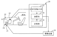
図1は、実施例を適用した車両Mのエンジン振動を除去する制御システムを構成図により概略的に示したものである。制御システムは、車両Mに搭載されて車体10にエンジン11を支持する能動型防振装置であるアクチュエータ搭載エンジンマウント(以下、エンジンマウントと記す)16と、制御信号を生成する制御装置20と、制御信号に基づいてアクチュエータを駆動する駆動装置25等を備えている。
Hereinafter, an embodiment of the present invention will be described with reference to the drawings.
FIG. 1 schematically shows a control system for removing engine vibrations of a vehicle M to which the embodiment is applied. The control system includes an actuator-mounted engine mount (hereinafter referred to as an engine mount) 16 that is an active vibration isolator that is mounted on the vehicle M and supports the engine 11 on the
エンジンマウント14は、筒状のケース(図示しない)内に、防振ゴムの変位によりエンジンの動的変位を制御するソレノイド、電磁石等である電磁アクチュエータ15を備えている。エンジンンマウント14は、下方の図示しない固定軸によって車体10に固定され、上方の図示しない固定軸にエンジン11を取り付けることにより、エンジン11を支持している。エンジン11のクランク軸には、回転パルスセンサ12が取り付けられており、回転パルスセンサ12は、エンジン回転数を検出して回転パルス信号を出力する。
The
制御装置20は、回転パルスセンサ12からの回転パルス信号Sを入力し、その周波数と各種運転状態(振幅及び位相に相関する)を読み取る信号読取り部21と、予め入力パルス信号Sに基づいて形成されたアイドル運転状態に対応する多数のアイドル制御信号データ及び走行運転状態に対応する走行制御信号データを記憶する記憶部22と、信号読取り部21からのデータ信に基づいて記憶部22から適正な制御信号データを選択し、制御信号を生成して出力する演算部23とにより構成されている。演算部23出力側には、電磁アクチュエータ15への通電をオンオフさせる上記駆動装置25が接続されている。
The
つぎに、制御信号Cの形成について説明する。
(1)アイドル運転状態
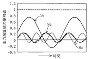
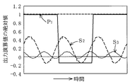
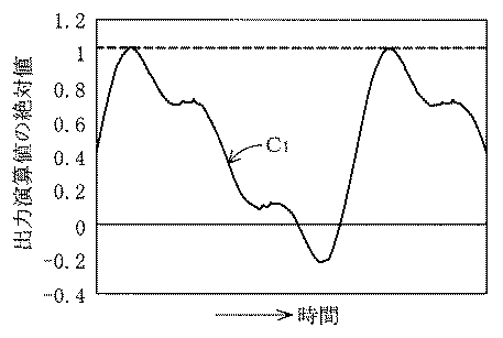
まず、車両のアイドル運転状態では、制御信号は、下記数1で表される制御周波数の正弦波信号である基本波S1、2次及び3次高調波信号成分S2,S3を合成した信号である。式中、k=1,2,3が周波数の次数を表し、an,φnは振幅及び位相を、nは時間を、ofsetは出力演算値のオフセット量をそれぞれ表す。図2−1は、基本波S1、2次成分及び3次成分S2,S3の正弦波信号を表し、図2−2はそれらを合成した出力演算値C1を表す。この出力演算値C1が、アイドル運転状態での各周波数についてデータマップとして記憶部22に記憶されている。
Next, the formation of the control signal C will be described.
(1) Idle operation state First, in the vehicle's idle operation state, the control signal is a fundamental wave S1, second and third harmonic signal components S2, S3 which are sine wave signals of a control frequency expressed by the following
(2)走行運転状態
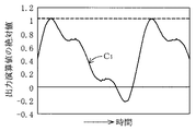
走行運転状態では、制御信号は、下記数2で表される制御周波数の正弦波信号である基本波S1のみで2次及び3次高調波信号成分を含まない正弦波信号について、下記数3で表される補正を加えた矩形波である出力演算値C2である。式中、k=1,2,3が周波数の次数を表し、an,φnは振幅及び位相を、nは時間を、ofsetは出力演算値のオフセット量をそれぞれ表す。図3−1は、正弦波信号である基本波を表し、図3−2は基本波を数3に従って補正した出力演算値C2を表す。この出力演算値C2が、走行運転状態での各周波数についてデータマップとして記憶部22に記憶されている。
(2) Traveling operation state In the traveling operation state, the control signal is a sine wave signal including only the fundamental wave S1, which is a sine wave signal having a control frequency expressed by the following
![]()
![]()
つぎに、上記のように構成された実施例の動作について説明する。
車両がアイドル運転状態にあるとき、制御装置20に入力パルス信号Sが入力され信号読取り部21で読み込まれる。さらに、演算部23において、信号読み取り部21からの入力パルス信号の周波数での振幅及び位相に対応するアイドル制御信号データが記憶部22から読み出される。演算部23は、アイドル制御信号データである制御周波数の基本波と2次及び3次高調波成分を重ね合せた出力演算値に基づいて、アイドル制御信号を生成して駆動装置25に出力する。駆動装置25は、入力されたアイドル制御信号に基づいて駆動信号を生成し、電磁アクチュエータ15に通電する。電磁アクチュエータ15が駆動されることにより、エンジンマウント14の加振力がエンジン側に及ぼされて、アイドル運転状態でのエンジン11の振動が抑制される。
Next, the operation of the embodiment configured as described above will be described.
When the vehicle is in an idle operation state, an input pulse signal S is input to the
ここで、アイドル制御信号には、制御周波数の正弦波信号である基本波成分に加えて2次及び3次高調波成分が含まれている。そのため、制御周波数のエンジン振動を適正に抑えることができると共に、制御周波数の2次及び3次高調波信号成分による騒音の発生を適正に抑えることができる。 Here, the idle control signal includes the second and third harmonic components in addition to the fundamental component which is a sine wave signal of the control frequency. Therefore, engine vibration at the control frequency can be properly suppressed, and generation of noise due to the second and third harmonic signal components of the control frequency can be appropriately suppressed.
一方、車両が高周波数の走行運転状態になると、演算部23において、信号読み取り部21からの入力パルス信号の周波数での振幅及び位相に対応する走行制御信号データが記憶部22から読み出される。演算部23は、走行制御信号データである制御周波数の正弦波信号を、上記数2に基づいて補正した出力演算値C2に基づいて、走行制御信号を演算により生成して駆動装置25に出力する。駆動装置25は、入力された走行制御信号に基づいて駆動信号を生成し、電磁アクチュエータ15に通電する。電磁アクチュエータ15が駆動されることにより、エンジンマウント14の加振力がエンジン側に及ぼされて、走行運転状態でのエンジン11の振動が抑制される。このように、走行制御信号は、正弦波の制御信号を矩形波に変換した矩形波信号であることにより、応答性の遅い電磁アクチュエータ15を駆動する際に、電磁アクチュエータ15の応答遅れを矩形波信号によりカバーすることができ、エンジンマウント14の十分な加振力が得られる。
On the other hand, when the vehicle is in a driving operation state at a high frequency, the
以上に説明したように、上記実施例によれば、車両のアイドル運転状態での低周波数の振動と、走行運転状態での高周波数の振動に対しては、それぞれ異なったアイドル制御信号と走行制御信号に分けて電磁アクチュエータ15を駆動するようにしたことにより、アイドル状態での2次及び3次の高調波成分による騒音の発生を抑えると共に、高周波数の走行状態での振動を応答性の遅い安価な電磁アクチュエータ15を用いても十分な加振力を確保できる。その結果、車両の広い範囲の運転状態全体にわたって、安価な電磁アクチュエータ15を用いることによっても騒音の発生を抑えつつエンジン振動を有効に抑えることができる。
As described above, according to the above-described embodiment, different idle control signals and traveling control are performed for low-frequency vibration in the idling operation state of the vehicle and high-frequency vibration in the traveling operation state. By driving the
つぎに、上記実施例の変形例について説明する。
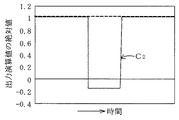
変形例においては、アイドル運転状態でのアイドル制御信号yは、下記数4で表されるように基本波を矩形波信号P1とし、2次及び3次高調波成分S2,S3を上記実施例と同様に正弦波信号とし、これらを重ね合せた信号としたものである。式中の符号については上記数1〜数3と同様である。図3−1は、基本波である矩形波信号P1と、2次及び3次高調波信号成分S2,S3の正弦波信号を表し、図3−2はそれらを合成した出力演算値C3を表す。ただし、出力演算値C3の絶対値の上限は1にされている。この出力演算値C3が、アイドル運転状態での各周波数についてデータマップとして記憶部22に記憶されている。
Next, a modification of the above embodiment will be described.
In the modified example, the idle control signal y in the idle operation state has a fundamental wave as a rectangular wave signal P1 as expressed by the following equation 4, and the second and third harmonic components S2 and S3 are the same as those in the above embodiment. Similarly, a sine wave signal is used and a signal obtained by superimposing these signals. The symbols in the formula are the same as in the
上記変形例においては、車両がアイドル運転状態にあるとき、アイドル制御信号には、制御周波数の矩形波信号である基本波成分に加えて2次及び3次高調波成分が含まれている。このように、制御周波数の信号を矩形波信号とすることにより、応答性の遅い電磁アクチュエータ15に対しても、不十分な応答性を補ってエンジンマウント14の加振力を高めることができ、制御周波数のエンジン振動を適正に抑えることができる。また、制御周波数に対する2次及び3次高調波信号成分による騒音の発生も適正に抑えられる。
In the above modification, when the vehicle is in the idling operation state, the idle control signal includes the second and third harmonic components in addition to the fundamental wave component which is a rectangular wave signal of the control frequency. Thus, by making the signal of the control frequency a rectangular wave signal, it is possible to increase the excitation force of the
なお、上記実施例においては、アイドル制御信号及び走行制御信号について、予め求めた制御信号データを記憶部に記憶し、入力信号に応じて演算部で記憶部から制御信号データを選択して制御信号を生成しているが、これに限らず、制御信号を適用制御法により形成するようにしてもよい。その他、上記実施例に示した能動型防振装置の制御装置については一例であり、本発明の趣旨を逸脱しない範囲において種々変更して実施することが可能である。 In the above-described embodiment, the control signal data obtained in advance for the idle control signal and the travel control signal is stored in the storage unit, and the control signal data is selected from the storage unit by the arithmetic unit according to the input signal. However, the present invention is not limited to this, and the control signal may be formed by an applied control method. In addition, the control device for the active vibration isolator shown in the above embodiment is merely an example, and various modifications can be made without departing from the spirit of the present invention.
本発明は、車両のアイドル運転状態での低周波数の振動と、走行運転状態での高周波数の振動に対しては、それぞれ異なった制御信号に分けて電磁アクチュエータを駆動するようにしたことにより、アイドル状態での制御周波数に対する2次及び3次の高調波信号成分による騒音の発生を抑えると共に、走行状態での高い周波数において、応答性の遅い安価な電磁アクチュエータを用いても十分な加振力を確保できる。このように、本発明は、車両の広い範囲の運転状態全体にわたって、安価な電磁アクチュエータを用いることによっても、騒音の発生を抑えつつエンジン振動を有効に抑えることができるので有用である。 According to the present invention, the low-frequency vibration in the idling operation state of the vehicle and the high-frequency vibration in the driving operation state are divided into different control signals to drive the electromagnetic actuator. Suppressing the generation of noise due to the second and third harmonic signal components with respect to the control frequency in the idle state, and sufficient excitation force even with the use of an inexpensive electromagnetic actuator with a slow response at a high frequency in the running state Can be secured. As described above, the present invention is useful because the engine vibration can be effectively suppressed while suppressing the generation of noise even by using an inexpensive electromagnetic actuator over a wide range of driving states of the vehicle.
11…エンジン、12…回転パルスセンサ、14…エンジンマウント、15…電磁アクチュエータ、20…制御装置、21…信号読取り部、22…記憶部、23…演算部、25…駆動装置。 DESCRIPTION OF SYMBOLS 11 ... Engine, 12 ... Rotation pulse sensor, 14 ... Engine mount, 15 ... Electromagnetic actuator, 20 ... Control apparatus, 21 ... Signal reading part, 22 ... Memory | storage part, 23 ... Calculation part, 25 ... Drive apparatus.
Claims (1)
車両のアイドル運転領域においては、前記制御周波数の正弦波信号あるいは該正弦波信号を矩形波に変換した矩形波信号に、該制御周波数に対する2次及び3次高調波信号成分を加えたアイドル制御信号に基づいて前記電磁アクチュエータを駆動し、
車両の走行運転領域においては、前記制御周波数の正弦波信号を矩形波に変換した矩形波信号である走行制御信号に基づいて前記電磁アクチュエータを駆動する
ことを特徴とする能動型防振装置の駆動方法。 A control signal having a control frequency based on a periodic pulse signal from the engine of the vehicle is generated, and an electromagnetic actuator of an active vibration isolator is driven based on the control signal. In a driving method of an active vibration isolator that suppresses vibration,
In an idle operation region of a vehicle, an idle control signal obtained by adding second and third harmonic signal components for the control frequency to a sine wave signal of the control frequency or a rectangular wave signal obtained by converting the sine wave signal into a rectangular wave. Driving the electromagnetic actuator based on
In the traveling operation region of a vehicle, the electromagnetic actuator is driven based on a traveling control signal that is a rectangular wave signal obtained by converting a sine wave signal of the control frequency into a rectangular wave. Method.
Priority Applications (4)
| Application Number | Priority Date | Filing Date | Title |
|---|---|---|---|
| JP2004118290A JP4016966B2 (en) | 2004-04-13 | 2004-04-13 | Driving method of active vibration isolator |
| GB0506815A GB2413193B (en) | 2004-04-13 | 2005-04-04 | Method for actuating active vibration insulators |
| US11/100,478 US7409268B2 (en) | 2004-04-13 | 2005-04-07 | Method for actuating active vibration insulators |
| CNB2005100651709A CN100442188C (en) | 2004-04-13 | 2005-04-13 | Actuation method of active type anti-vibration device |
Applications Claiming Priority (1)
| Application Number | Priority Date | Filing Date | Title |
|---|---|---|---|
| JP2004118290A JP4016966B2 (en) | 2004-04-13 | 2004-04-13 | Driving method of active vibration isolator |
Publications (2)
| Publication Number | Publication Date |
|---|---|
| JP2005299832A true JP2005299832A (en) | 2005-10-27 |
| JP4016966B2 JP4016966B2 (en) | 2007-12-05 |
Family
ID=34587751
Family Applications (1)
| Application Number | Title | Priority Date | Filing Date |
|---|---|---|---|
| JP2004118290A Expired - Fee Related JP4016966B2 (en) | 2004-04-13 | 2004-04-13 | Driving method of active vibration isolator |
Country Status (4)
| Country | Link |
|---|---|
| US (1) | US7409268B2 (en) |
| JP (1) | JP4016966B2 (en) |
| CN (1) | CN100442188C (en) |
| GB (1) | GB2413193B (en) |
Cited By (7)
| Publication number | Priority date | Publication date | Assignee | Title |
|---|---|---|---|---|
| JP2007285377A (en) * | 2006-04-14 | 2007-11-01 | Aisin Seiki Co Ltd | Vibration damping device |
| JP2007285378A (en) * | 2006-04-14 | 2007-11-01 | Aisin Seiki Co Ltd | Vibration damping device |
| WO2007129627A1 (en) * | 2006-05-08 | 2007-11-15 | Shinko Electric Co., Ltd. | Damper for automobiles for reducing vibration of automobile body |
| JP2008120115A (en) * | 2006-11-08 | 2008-05-29 | Aisin Seiki Co Ltd | Active vibration isolator |
| JP2013028303A (en) * | 2011-07-29 | 2013-02-07 | Nissan Motor Co Ltd | Anti-vibration device for vehicle |
| CN102981522A (en) * | 2012-11-29 | 2013-03-20 | 中国科学院武汉物理与数学研究所 | Small active vibration control system based on piezoelectric ceramic and piezoelectric accelerometer |
| JP2015175461A (en) * | 2014-03-17 | 2015-10-05 | Necプラットフォームズ株式会社 | On-vehicle vibration suppression device |
Families Citing this family (15)
| Publication number | Priority date | Publication date | Assignee | Title |
|---|---|---|---|---|
| JP4370933B2 (en) * | 2004-02-20 | 2009-11-25 | 東海ゴム工業株式会社 | Vibration control method and vibration control device for active vibration isolator |
| JP2006194271A (en) * | 2005-01-11 | 2006-07-27 | Honda Motor Co Ltd | Active anti-vibration support device |
| DE102007042222A1 (en) * | 2007-09-05 | 2009-03-12 | Robert Bosch Gmbh | Method and device for reducing vibrations when stopping or starting engines, in particular internal combustion engines |
| EP2278188A4 (en) * | 2008-05-14 | 2013-04-03 | Sinfonia Technology Co Ltd | Vibration control device and vehicle |
| WO2010084842A1 (en) * | 2009-01-20 | 2010-07-29 | 本田技研工業株式会社 | Vehicle-mounted active vibration reducing device |
| JP5569195B2 (en) * | 2010-07-02 | 2014-08-13 | シンフォニアテクノロジー株式会社 | Linear actuator drive unit |
| DE102016213483B4 (en) | 2016-07-22 | 2022-03-31 | Ford Global Technologies, Llc | Device for compensating free mass forces of a reciprocating internal combustion engine |
| CN108327503B (en) * | 2017-01-20 | 2019-12-20 | 比亚迪股份有限公司 | Hybrid electric vehicle and active vibration damping control method and device thereof |
| CN108327504B (en) * | 2017-01-20 | 2019-12-20 | 比亚迪股份有限公司 | Automobile and active vibration damping control method and device thereof |
| CN108327505B (en) * | 2017-01-20 | 2020-01-03 | 比亚迪股份有限公司 | Automobile and active vibration damping control method and device thereof |
| JP6846213B2 (en) * | 2017-01-20 | 2021-03-24 | 山洋電気株式会社 | Motor control device |
| CN108327507B (en) * | 2017-01-20 | 2020-05-19 | 比亚迪股份有限公司 | Hybrid electric vehicle and active vibration reduction control method and device thereof |
| CN110657193B (en) * | 2018-06-29 | 2021-04-20 | 比亚迪股份有限公司 | Automobile and active vibration damping control method and device thereof |
| CN116146342B (en) * | 2021-11-23 | 2025-12-02 | 中车株洲电力机车研究所有限公司 | Engine active suspension hybrid control method, device, equipment and storage medium |
| CN115234602B (en) * | 2022-07-08 | 2024-10-29 | 南京航空航天大学 | Control strategy and operation method of active vibration damping device for safe transportation of large precision equipment |
Family Cites Families (16)
| Publication number | Priority date | Publication date | Assignee | Title |
|---|---|---|---|---|
| JPS5011784B1 (en) * | 1969-08-22 | 1975-05-06 | ||
| JPH0778680B2 (en) * | 1989-07-24 | 1995-08-23 | 日産自動車株式会社 | Vehicle interior noise reduction device |
| DE4104168C1 (en) * | 1991-02-12 | 1992-04-02 | Fa. Carl Freudenberg, 6940 Weinheim, De | |
| JP3550153B2 (en) * | 1991-07-05 | 2004-08-04 | 本田技研工業株式会社 | Reference signal generation device for active vibration control device related to internal combustion engine |
| DE69423531T2 (en) * | 1993-02-02 | 2000-07-20 | Honda Giken Kogyo K.K., Tokio/Tokyo | Vibration / noise reduction device |
| US5893892A (en) * | 1994-12-29 | 1999-04-13 | Dana Corporation | Vibration sensing and diagnostic system for vehicle drive train components |
| JP3751359B2 (en) * | 1996-03-21 | 2006-03-01 | 本田技研工業株式会社 | Vibration noise control device |
| JPH09280307A (en) * | 1996-04-10 | 1997-10-28 | Nissan Motor Co Ltd | Active vibration control device for vehicles |
| JP3228153B2 (en) * | 1996-11-08 | 2001-11-12 | 日産自動車株式会社 | Active vibration control device |
| JP3451891B2 (en) * | 1997-06-13 | 2003-09-29 | 日産自動車株式会社 | Active vibration control device |
| JP3952584B2 (en) | 1997-12-05 | 2007-08-01 | 東海ゴム工業株式会社 | Active vibration isolator |
| JP3575270B2 (en) * | 1998-03-04 | 2004-10-13 | 東海ゴム工業株式会社 | Active vibration isolator |
| JP3719067B2 (en) | 1999-10-21 | 2005-11-24 | 東海ゴム工業株式会社 | Control method of electromagnetic vibration device and electromagnetic vibration device |
| JP2002005227A (en) * | 2000-06-19 | 2002-01-09 | Tokai Rubber Ind Ltd | Control data setting method and data recording medium for active mount control device |
| JP2002174288A (en) * | 2000-12-05 | 2002-06-21 | Tokai Rubber Ind Ltd | Pneumatic active vibration isolator |
| CN1367390A (en) * | 2001-01-20 | 2002-09-04 | 上海科星自动化技术有限公司 | Impulse current signal detection device |
-
2004
- 2004-04-13 JP JP2004118290A patent/JP4016966B2/en not_active Expired - Fee Related
-
2005
- 2005-04-04 GB GB0506815A patent/GB2413193B/en not_active Expired - Fee Related
- 2005-04-07 US US11/100,478 patent/US7409268B2/en active Active
- 2005-04-13 CN CNB2005100651709A patent/CN100442188C/en not_active Expired - Fee Related
Cited By (15)
| Publication number | Priority date | Publication date | Assignee | Title |
|---|---|---|---|---|
| JP2007285378A (en) * | 2006-04-14 | 2007-11-01 | Aisin Seiki Co Ltd | Vibration damping device |
| JP2007285377A (en) * | 2006-04-14 | 2007-11-01 | Aisin Seiki Co Ltd | Vibration damping device |
| US8047512B2 (en) | 2006-04-14 | 2011-11-01 | Aisin Seiki Kabushiki Kaisha | Vibration damping apparatus |
| US8626386B2 (en) | 2006-05-08 | 2014-01-07 | Shinko Electric Co., Ltd. | Damping apparatus for reducing vibration of automobile body |
| WO2007129627A1 (en) * | 2006-05-08 | 2007-11-15 | Shinko Electric Co., Ltd. | Damper for automobiles for reducing vibration of automobile body |
| JPWO2007129627A1 (en) * | 2006-05-08 | 2009-09-17 | シンフォニアテクノロジー株式会社 | Vibration control device |
| US8892338B2 (en) | 2006-05-08 | 2014-11-18 | Shinko Electric Co., Ltd. | Damping apparatus for reducing vibration of automobile body |
| US8401735B2 (en) | 2006-05-08 | 2013-03-19 | Shinko Electric Co., Ltd. | Damping apparatus for reducing vibration of automobile body |
| US8818625B2 (en) | 2006-05-08 | 2014-08-26 | Shinko Electric Co., Ltd. | Damping apparatus for reducing vibrations |
| US8504239B2 (en) | 2006-05-08 | 2013-08-06 | Shinko Electric Co., Ltd. | Damping apparatus for reducing vibration of automobile body |
| JP2008120115A (en) * | 2006-11-08 | 2008-05-29 | Aisin Seiki Co Ltd | Active vibration isolator |
| JP2013028303A (en) * | 2011-07-29 | 2013-02-07 | Nissan Motor Co Ltd | Anti-vibration device for vehicle |
| CN102981522A (en) * | 2012-11-29 | 2013-03-20 | 中国科学院武汉物理与数学研究所 | Small active vibration control system based on piezoelectric ceramic and piezoelectric accelerometer |
| CN102981522B (en) * | 2012-11-29 | 2015-03-25 | 中国科学院武汉物理与数学研究所 | Small active vibration control system based on piezoelectric ceramic and piezoelectric accelerometer |
| JP2015175461A (en) * | 2014-03-17 | 2015-10-05 | Necプラットフォームズ株式会社 | On-vehicle vibration suppression device |
Also Published As
| Publication number | Publication date |
|---|---|
| US7409268B2 (en) | 2008-08-05 |
| CN100442188C (en) | 2008-12-10 |
| JP4016966B2 (en) | 2007-12-05 |
| GB2413193B (en) | 2006-04-05 |
| GB2413193A (en) | 2005-10-19 |
| GB0506815D0 (en) | 2005-05-11 |
| CN1684014A (en) | 2005-10-19 |
| US20050248070A1 (en) | 2005-11-10 |
Similar Documents
| Publication | Publication Date | Title |
|---|---|---|
| JP4016966B2 (en) | Driving method of active vibration isolator | |
| JP5522038B2 (en) | Vibration control device and vehicle | |
| CN103140698B (en) | The controlling method of active damper, vehicle, active damper | |
| KR101140925B1 (en) | Damper for automobiles for reducing vibration of automobile body | |
| JP5522037B2 (en) | Vibration control device and vehicle | |
| JP5098796B2 (en) | Vibration control device and vehicle | |
| JP3297024B2 (en) | Device for supporting vibration components | |
| JP4370933B2 (en) | Vibration control method and vibration control device for active vibration isolator | |
| JP5120707B2 (en) | Vibration control device and vehicle | |
| WO2013133189A1 (en) | Vibration suppression device for vehicle | |
| JP2009275820A (en) | Vibration damping device and vehicle | |
| JP5085360B2 (en) | Active vibration isolator | |
| JP2010216494A (en) | Transmitted vibration reducing structure | |
| JP2020070895A (en) | Vibration damping device | |
| HK1154642B (en) | Vibration control device and vehicle | |
| JPH06109059A (en) | Vehicle vibration reduction device | |
| HK1154643B (en) | Vibration control device and vehicle | |
| JPH08177966A (en) | Active vibration control device and active vibration control method | |
| HK1127795B (en) | Damper for automobiles for reducing vibration of automobile body |
Legal Events
| Date | Code | Title | Description |
|---|---|---|---|
| A621 | Written request for application examination |
Free format text: JAPANESE INTERMEDIATE CODE: A621 Effective date: 20060823 |
|
| A977 | Report on retrieval |
Free format text: JAPANESE INTERMEDIATE CODE: A971007 Effective date: 20070516 |
|
| A131 | Notification of reasons for refusal |
Free format text: JAPANESE INTERMEDIATE CODE: A131 Effective date: 20070529 |
|
| A521 | Request for written amendment filed |
Free format text: JAPANESE INTERMEDIATE CODE: A523 Effective date: 20070730 |
|
| TRDD | Decision of grant or rejection written | ||
| A01 | Written decision to grant a patent or to grant a registration (utility model) |
Free format text: JAPANESE INTERMEDIATE CODE: A01 Effective date: 20070828 |
|
| A61 | First payment of annual fees (during grant procedure) |
Free format text: JAPANESE INTERMEDIATE CODE: A61 Effective date: 20070910 |
|
| R150 | Certificate of patent or registration of utility model |
Ref document number: 4016966 Country of ref document: JP Free format text: JAPANESE INTERMEDIATE CODE: R150 Free format text: JAPANESE INTERMEDIATE CODE: R150 |
|
| FPAY | Renewal fee payment (event date is renewal date of database) |
Free format text: PAYMENT UNTIL: 20100928 Year of fee payment: 3 |
|
| FPAY | Renewal fee payment (event date is renewal date of database) |
Free format text: PAYMENT UNTIL: 20110928 Year of fee payment: 4 |
|
| FPAY | Renewal fee payment (event date is renewal date of database) |
Free format text: PAYMENT UNTIL: 20110928 Year of fee payment: 4 |
|
| FPAY | Renewal fee payment (event date is renewal date of database) |
Free format text: PAYMENT UNTIL: 20120928 Year of fee payment: 5 |
|
| FPAY | Renewal fee payment (event date is renewal date of database) |
Free format text: PAYMENT UNTIL: 20120928 Year of fee payment: 5 |
|
| FPAY | Renewal fee payment (event date is renewal date of database) |
Free format text: PAYMENT UNTIL: 20130928 Year of fee payment: 6 |
|
| LAPS | Cancellation because of no payment of annual fees |