JP2005299812A - Fluid-pressure actuator - Google Patents
Fluid-pressure actuator Download PDFInfo
- Publication number
- JP2005299812A JP2005299812A JP2004117692A JP2004117692A JP2005299812A JP 2005299812 A JP2005299812 A JP 2005299812A JP 2004117692 A JP2004117692 A JP 2004117692A JP 2004117692 A JP2004117692 A JP 2004117692A JP 2005299812 A JP2005299812 A JP 2005299812A
- Authority
- JP
- Japan
- Prior art keywords
- rod
- chamber
- fluid pressure
- diaphragm
- vibration
- Prior art date
- Legal status (The legal status is an assumption and is not a legal conclusion. Google has not performed a legal analysis and makes no representation as to the accuracy of the status listed.)
- Granted
Links
Images


Landscapes
- Actuator (AREA)
Abstract
Description
本発明は、流体圧によるエネルギーを機械的エネルギーに変換する流体圧アクチュエータに関するものである。 The present invention relates to a fluid pressure actuator that converts energy generated by fluid pressure into mechanical energy.
従来、吸気制御弁,バタフライバルブ,ターボチャージャの過給圧を制御するウェイストゲートバルブなどの各種制御弁の駆動や、その他の駆動部品の駆動を行うために用いられる流体圧アクチュエータが知られている(例えば、特許文献1参照)。この種の流体アクチュエータとしては、例えば、図9に示すものがある。図9は従来例に係る流体圧アクチュエータの模式的断面図である。 Conventionally, fluid pressure actuators used for driving various control valves such as an intake control valve, a butterfly valve, a waste gate valve for controlling a supercharging pressure of a turbocharger, and other driving components are known. (For example, refer to Patent Document 1). An example of this type of fluid actuator is shown in FIG. FIG. 9 is a schematic sectional view of a fluid pressure actuator according to a conventional example.
図示のように、流体圧アクチュエータ100は、ロアーカップ101とアッパーカップ102からなるケース内にダイアフラム103が設けられる。このダイアフラム103によって、ケース内が、2つの室に区画される。そして、ロアーカップ101側の室の内部は大気圧に保たれる。一方、アッパーカップ102側の室の内部に外気が導入され、または当該室内から空気が排出されることによって、室内の流体圧力は変動する。この流体圧力の変動に応じてダイアフラム103は変形する。このダイアフラム103の変形にしたがって、ダイアフラム103に固定されたロッド104は移動する。
As illustrated, the
このように、アッパーカップ102側の室内の流体圧力を変えて、ダイアフラム103の変形による変位量を制御することで、ロッド104を往復移動させることが可能となる。また、ロッド104のダイアフラム103への固定側とは反対側の端部には、機械的な運動を行わせるための機構が設けられている。例えば、回転軸に固定された回転体の回転中心と偏心する位置に、ロッド104の端部が固定されることで、ロッド104の往復運動を回転軸の回転運動に変換させることができる。この場合、ロッド104は往復移動を行いつつ、揺動することになる。従って、ロッド104の軸受け105は、ロッド104の揺動を許容しつつ、往復移動するロッド104を支持するように構成されている。図示の例では、軸受け105は、断面が樽形状で構成されることにより、ロッド104の揺動を許容しつつ、往復移動するロッド104を支持することができる。
In this way, the
以上のように構成される流体圧アクチュエータ100においては、使用環境等によっては、ロッド104やロッド104が固定されたダイアフラム103が激しく振動してしまうことがある。例えば、自動車内の各種制御弁を駆動するために、流体圧アクチュエータ100を用いた場合、吸気や排気の脈動によって、ロッド104が細かく、かつ激しく振動することがある。かかる振動は、ロッド104及びダイアフラム103や、ロッド104に連結された各部部品の磨耗を促進してしまったり、騒音を発生させたりする原因となる。
本発明の目的の1つとして、ロッドの振動を抑制することが挙げられる。 One of the objects of the present invention is to suppress the vibration of the rod.
本発明の目的の1つとして、耐久性の向上を図ることが挙げられる。 One of the objects of the present invention is to improve durability.
本発明の目的の1つとして、騒音の発生を抑制することが挙げられる。 One of the objects of the present invention is to suppress the generation of noise.
本発明は、上記課題を解決するために以下の手段を採用した。 The present invention employs the following means in order to solve the above problems.
本発明の流体圧アクチュエータは、
ケースの内部を、室内の流体圧力が制御される第1室と室内が大気圧に保たれる第2室に区画するダイアフラムと、
第1室内の流体圧力の変化に応じて変形するダイアフラムに連動して、揺動しつつ往復運動を行うロッドと、を備え、
第1室内の流体圧力によるエネルギーを、前記ダイアフラム及びロッドを利用して機械的エネルギーに変換する流体圧アクチュエータであって、
第2室内に設けられると共に、ロッドの揺動を許容しつつ、往復移動するロッドを支持する軸受けと、
第2室内に設けられると共に、周方向に複数設けられた凸部がロッドに当接して、該ロッドの振動を吸収する環状の防振部材と、を備えることを特徴とする。
The fluid pressure actuator of the present invention is
A diaphragm that divides the interior of the case into a first chamber in which the fluid pressure in the chamber is controlled and a second chamber in which the chamber is maintained at atmospheric pressure;
A rod that reciprocates while swinging in conjunction with a diaphragm that deforms in response to a change in fluid pressure in the first chamber,
A fluid pressure actuator that converts energy generated by fluid pressure in the first chamber into mechanical energy using the diaphragm and the rod,
A bearing that is provided in the second chamber and supports the rod that reciprocates while allowing the rod to swing;
An annular vibration isolating member that is provided in the second chamber and has a plurality of convex portions provided in the circumferential direction abuts on the rod and absorbs vibration of the rod.
本発明の構成によれば、防振部材によって、ロッドの振動が吸収される。また、本発明においては、周方向に複数設けられた凸部がロッドに当接することで、ロッドの振動を吸収する。そのため、ロッドの全周に防振部材が当接する訳ではないので、ロッドに対する摺動抵抗が高くなり過ぎることもない。また、第2室内を密封してしまうこともなく、第2室内は大気圧状態が好適に維持される。以上のことから、ロッドの滑らかな移動を維持できる。 According to the configuration of the present invention, the vibration of the rod is absorbed by the vibration isolating member. Moreover, in this invention, the convex part provided in the circumferential direction contact | abuts to a rod, and absorbs the vibration of a rod. Therefore, since the vibration isolating member does not contact the entire circumference of the rod, the sliding resistance against the rod does not become too high. In addition, the second chamber is suitably maintained in an atmospheric pressure state without sealing the second chamber. From the above, the smooth movement of the rod can be maintained.
また、前記防振部材の外周に、複数の凸部のロッドに対する押圧力を増加させる締め付け部材が設けられるとよい。 Moreover, it is good for the outer periphery of the said vibration-proof member to provide the fastening member which increases the pressing force with respect to the rod of a some convex part.
このように締め付け部材を設ければ、ロッドが停止した際に、ロッドに残る振動を素早く停止させることができる。また、防振部材の凸部が経時劣化により磨耗した場合にあっても、凸部をロッドに対して当接させた状態を維持できる。従って、経時的な防振効果の低下を抑制できる。 If the tightening member is provided in this way, the vibration remaining on the rod can be quickly stopped when the rod is stopped. Moreover, even when the convex portion of the vibration isolating member is worn due to deterioration with time, the state in which the convex portion is in contact with the rod can be maintained. Therefore, it is possible to suppress a decrease in the vibration isolation effect over time.
以上説明したように、本発明によれば、ロッドの振動を抑制できる。また、これに伴い、各部品の磨耗を抑制することができ、耐久性の向上を図ることができる。更に、ロッドの振動を起因とする騒音の発生を抑制できる。 As described above, according to the present invention, the vibration of the rod can be suppressed. Further, along with this, it is possible to suppress wear of each component, and to improve durability. Furthermore, the generation of noise due to rod vibration can be suppressed.
以下に図面を参照して、この発明を実施するための最良の形態を、実施例に基づいて例示的に詳しく説明する。ただし、この実施例に記載されている構成部品の寸法、材質、形状、その相対配置などは、特に特定的な記載がない限りは、この発明の範囲をそれらのみに限定する趣旨のものではない。 The best mode for carrying out the present invention will be exemplarily described in detail below with reference to the drawings. However, the dimensions, materials, shapes, relative arrangements, and the like of the components described in this embodiment are not intended to limit the scope of the present invention only to those unless otherwise specified. .
図1〜図4を参照して、本発明の実施例1に係る流体圧アクチュエータについて説明する。 A fluid pressure actuator according to a first embodiment of the present invention will be described with reference to FIGS.
<流体圧アクチュエータの全体説明>
図1を参照して、本発明の実施例1に係る流体圧アクチュエータ全体の構成について説明する。図1は本発明の実施例1に係る流体圧アクチュエータの模式的断面図である。
<Overall description of fluid pressure actuator>
With reference to FIG. 1, the structure of the whole fluid pressure actuator which concerns on Example 1 of this invention is demonstrated. FIG. 1 is a schematic cross-sectional view of a fluid pressure actuator according to a first embodiment of the present invention.
図示のように、流体圧アクチュエータ1は、ロアーカップ10とアッパーカップ20か
らなるケースと、ケース内に設けられるダイアフラム30と、ダイアフラム30に一端が固定されるロッド40とを備える。ロアーカップ10は、おおよそカップの形状をしており、その底に、ロッド40が挿通される挿通孔11が設けられている。アッパーカップ20も、おおよそカップの形状をしており、その底に、配管70が接続される貫通孔21が設けられている。これらのロアーカップ10とアッパーカップ20は、その開口端部同士が合わさるように固定される。そして、ダイアフラム30は、その周囲が、これらのロアーカップ10とアッパーカップ20の固定部にて固定されている。これにより、ダイアフラム30は、ケースの内部を第1室R1と第2室R2に区画している。
As illustrated, the
ロッド40は、その一端が、ダイアフラム30に対して、例えばネジ止めにより固定される。ここで、ダイアフラム30とロッド40の固定部においては、ダイアフラム30を挟み込むように、第1リテーナ81及び第2リテーナ82が設けられている。これらの第1リテーナ81及び第2リテーナ82によって、ダイアフラム30は、中央付近は変形せず、その周囲のみが変形するように機能する。これにより、ダイアフラム30は、ある程度規則的に変形する。なお、ロッド40はダイアフラム30に対して直接固定させることもできるし、第1リテーナ81及び第2リテーナ82を介して間接的に固定させることもできる(例えば、第1リテーナ81及び第2リテーナ82をロッド40の端部にボルトで締結することによって、これらのリテーナによりダイアフラム30を挟み込んでロッド40を間接的にダイアフラムに固定できる)。また、ダイアフラム30は、ゴムや樹脂などの柔軟性の高い材料によって構成される。そして、第1リテーナ81及び第2リテーナ82は、金属等の剛性の高い材料によって構成される。
One end of the
また、ロアーカップ10の内部には、スプリング60が設けられる。このスプリング60は、その一端が、第2リテーナ82に当接し、他端が、ロアーカップ10の底に当接するように配設される。また、ロアーカップ10の底の外側には、流体圧アクチュエータ1を所望の位置に取り付けるための支持部材90が設けられている。
A
<流体圧アクチュエータの動作>
上述のように構成された流体圧アクチュエータ1において、配管70を介して、第1室R1内に気体(例えば空気)が導入され、または第1室R1内から気体が排出される。このような第1室R1内の気体の量に応じて、第1室R1の内部の流体圧力は変動する。一方、第2室R2内は大気圧に保たれる。また、第1室R1内部の流体圧力の変動に応じてダイアフラム30は変形する。このダイアフラム30の変形は、上記の通りある程度規則性がある。そして、第1室R1内の流体圧力とスプリング60のバネ力との釣り合いによって、ダイアフラム30の変形に伴うロッド40の変位量が定まる。
<Operation of fluid pressure actuator>
In the
以上のことから、第1室R1内への気体の導入量や排出量を制御することで、第1室R1の内部の流体圧力が変動し、ロッド40の変位量を制御することができる。これにより、例えば、ロッド40を往復運動させることができる。
From the above, by controlling the amount of gas introduced into and discharged from the first chamber R1, the fluid pressure inside the first chamber R1 varies, and the displacement of the
ロッド40におけるダイアフラム30への固定部と反対側の端部には、機械的な運動を行わせるための機構(不図示)への取り付け部41が設けられている。例えば、回転軸に固定された回転体(回転板)に対して、回転軸と偏心する位置に、この取り付け部41が固定される。これにより、ロッド40が往復移動することにより、回転体が回転し回転軸が回転する。これにより、例えば、回転軸に取り付けられた弁体が回転し、弁を開いたり閉じたりする制御を行うことができる。なお、ロッド40の往復運動を他の部材の回転運動に変換する機構等については、公知技術であるので、その詳細説明は省略する。
An
以上のように、流体圧アクチュエータ1は、流体圧(気圧)によるエネルギーを機械的エネルギーに変換することができる。
As described above, the
<軸受け及び防振部材>
特に、図2〜図4を参照して、本発明の実施例1に係る軸受け及び防振部材について説明する。図2は図1中A部の拡大図である。図3は本発明の実施例1に係る防振部材の平面図である。図4は本発明の実施例1に係る防振部材の模式的断面図(軸心を通るように切断した断面図)である。
<Bearing and vibration isolation member>
In particular, a bearing and a vibration isolating member according to
ロアーカップ10の底に設けられた挿通孔11付近には、ロッド40の軸受け52が設けられている。この軸受け52は環状の部材であり、ロッド40の外周に嵌め込まれる。この軸受け52は、金属や樹脂材など、比較的剛性の高い材料により構成される。また、軸受け52の内周面とロッド40の外周面との間には適度なクリアランスが設けられている。そして、このクリアランスを介して、気体は、第2室R2の内外を自由に行き来することができる。
Near the
ここで、上記の通り、ロッド40の往復運動を回転軸の回転運動に変換する場合には、ロッド40の端部に設けられた取り付け部41は、回転軸の周囲を回転するように移動する。そのため、ロッド40は往復移動を行いつつ、揺動することになる。従って、軸受け52は、ロッド40の揺動を許容しつつ、往復移動するロッド40を支持するように構成されている。図示の例では、軸受け52は、断面が樽形状で構成されることにより、ロッド40の揺動を許容しつつ、往復移動するロッド40を支持することができる。
Here, as described above, when the reciprocating motion of the
また、軸受け52に隣接して、防振部材53が設けられている。この防振部材53も環状の部材であり、ロッド40の外周に嵌め込まれる。この防振部材53は、ゴム(例えば、HNBR,シリコン、フッ素系ゴム)や樹脂材など弾性材料により構成される。
Further, a
この防振部材53は、軸受け52に当接して、軸受け52の軸方向の位置決めを行う当接部53aと、ロッド40に当接する凸部53b,53cと、支持部材51が嵌め込まれる溝53dとを備えている。凸部53b,53cは、軸方向の一端側(軸受け52側)と他端側に、それぞれ周方向に等間隔に4個づつ設けられている。これらの凸部53b,53cは、ある程度の締め代をもってロッド40に対して当接するように構成されている。また、これらの凸部53b,53cによるロッド40に対する摺動抵抗は、ロッド40の円滑な移動が妨げられないようにする必要がある。この摺動抵抗の調整は、防振部材53の材質や硬度、あるいは、凸部53b,53cの形状,個数及び締め代等により行うことができる。
The
以上のような構成により、ロッド40の振動は、複数の凸部53b,53cを介して防振部材53に吸収されるため、ロッド40の振動が抑制される。また、防振部材53は、複数の凸部53b,53cがロッド40に対して部分的に当接することから、ロッド40の外周面と防振部材53の内周面との間には気体の通り道がある。そのため、気体は、第2室R2の内外を自由に行き来することができる。従って、第2室R2内は大気圧状態が保たれる。
With the above configuration, the vibration of the
支持部材51は、筒状の部材であり、軸受け52と防振部材53の外周に嵌め込まれる。この支持部材51は、金属など、比較的剛性の高い材料により構成される。また、この支持部材51は、筒状部分の一端は外側に折り曲げられており、他端は内側に折り曲げられている。そして、外側に折り曲げられた部分がロアーカップ10の底側に固定され、内側に折り曲げられた部分が防振部材53の溝53dに嵌め込まれる。この支持部材51が、防振部材53の位置決めを行う。
The
<本実施例に係る流体圧アクチュエータの効果>
本実施例に係る流体圧アクチュエータ1によれば、防振部材53を設けたことにより、ロッド40の振動を抑制することができる。これにより、各種部品(特に、ロッド40の移動によって駆動される部品)の磨耗を抑制することができる。従って、各種部品の耐久性の向上を図ることができる。また、ロッド40の振動を起因とする騒音の発生を抑制できる。なお、上記の通り、防振部材53を設けても、ロッド40の円滑な運動を妨げるものでもなく、かつ、第2室R2内の大気圧状態は良好に保たれる。
<Effect of the fluid pressure actuator according to this embodiment>
According to the
図5及び図6には、本発明の実施例2が示されている。本実施例では、防振部材の形状の変更例を説明する。その他の基本的な構成および作用については実施例1と同一なので、同一の構成部分については、その説明は省略する。図5は本発明の実施例2に係る防振部材の平面図である。図6は本発明の実施例2に係る防振部材の模式的断面図(軸心を通るように切断した断面図)である。 5 and 6 show a second embodiment of the present invention. In this embodiment, an example of changing the shape of the vibration isolation member will be described. Since other basic configurations and operations are the same as those in the first embodiment, the description of the same components will be omitted. FIG. 5 is a plan view of a vibration isolating member according to Embodiment 2 of the present invention. FIG. 6 is a schematic cross-sectional view (cross-sectional view cut along the axis) of the vibration isolator according to Embodiment 2 of the present invention.
本実施例に係る防振部材53Aは、周方向に等間隔に4個のスリット53eが設けられている。本実施例に係る防振部材53Aにおいては、これらのスリット53e以外の部分が上記実施例1における防振部材53の凸部53bに相当する。つまり、これらのスリット53e以外の部分がロッド40に当接する。なお、本実施例に係る防振部材53Aの内周面側の径は、軸方向で異なっている。すなわち、スリット53eが設けられている領域における径はロッド40の径よりも僅かに小さく、スリット53eが設けられていない領域における径はロッド40の径よりも僅かに大きい。従って、径方向におけるスリット53eが設けられている領域においてのみ、スリット53eが設けられていない部分がロッド40に当接する。
The
以上のように構成された防振部材53Aにおいても、上記実施例1と同様の効果を得ることができることは言うまでもない。
It goes without saying that the same effects as those of the first embodiment can be obtained in the
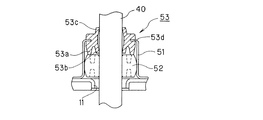
図7及び図8には、本発明の実施例3が示されている。本実施例では、上記実施例1の構成に、締め付け部材を加えた例を説明する。その他の基本的な構成および作用については実施例1と同一なので、同一の構成部分については、同一の符号を付して、その説明は省略する。図7は本発明の実施例3に係る防振部材の模式的断面図(軸心を通るように切断した断面図)である。図8は本発明の実施例3に係る流体圧アクチュエータの模式的断面図の一部拡大図(実施例1における図2に相当する図)である。 7 and 8 show a third embodiment of the present invention. In this embodiment, an example in which a tightening member is added to the configuration of the first embodiment will be described. Since other basic configurations and operations are the same as those of the first embodiment, the same components are denoted by the same reference numerals and description thereof is omitted. FIG. 7 is a schematic cross-sectional view (cross-sectional view cut along the axis) of the vibration isolator according to Embodiment 3 of the present invention. FIG. 8 is a partially enlarged view of a schematic cross-sectional view of a fluid pressure actuator according to a third embodiment of the present invention (a diagram corresponding to FIG. 2 in the first embodiment).
本実施例に係る防振部材53Bの基本的な構成は、上記実施例1における防振部材53とほぼ同一である。ただし、本実施例に係る防振部材53Bにおいては、一方の端部側の外周に、締め付け部材としてのスプリング54が嵌め込まれる点のみが実施例1における防振部材53と異なる。このスプリング54を設けたことにより、防振部材53Bが外周側から締め付けられ、凸部53cのロッド40に対する押圧力を増加させることができる。これにより、ロッド40が停止した際に、ロッド40に残る振動を素早く停止させることができる。また、凸部53cが経時劣化により磨耗した場合にあっても、凸部53cをロッド40に対して当接させた状態を維持できる。従って、経時的な防振効果の低下を抑制できる。
The basic configuration of the
1 流体圧アクチュエータ
10 ロアーカップ
11 挿通孔
20 アッパーカップ
21 貫通孔
30 ダイアフラム
40 ロッド
41 取り付け部
51 支持部材
52 軸受け
53,53A,53B 防振部材
53a 当接部
53b,53c 凸部
53d 溝
53e スリット
54 スプリング
60 スプリング
70 配管
81 第1リテーナ
82 第2リテーナ
90 支持部材
R1 第1室
R2 第2室
DESCRIPTION OF
Claims (2)
第1室内の流体圧力の変化に応じて変形するダイアフラムに連動して、揺動しつつ往復運動を行うロッドと、を備え、
第1室内の流体圧力によるエネルギーを、前記ダイアフラム及びロッドを利用して機械的エネルギーに変換する流体圧アクチュエータであって、
第2室内に設けられると共に、ロッドの揺動を許容しつつ、往復移動するロッドを支持する軸受けと、
第2室内に設けられると共に、周方向に複数設けられた凸部がロッドに当接して、該ロッドの振動を吸収する環状の防振部材と、を備えることを特徴とする流体圧アクチュエータ。 A diaphragm that divides the interior of the case into a first chamber in which the fluid pressure in the chamber is controlled and a second chamber in which the chamber is maintained at atmospheric pressure;
A rod that reciprocates while swinging in conjunction with a diaphragm that deforms in response to a change in fluid pressure in the first chamber,
A fluid pressure actuator that converts energy generated by fluid pressure in the first chamber into mechanical energy using the diaphragm and the rod,
A bearing that is provided in the second chamber and supports the rod that reciprocates while allowing the rod to swing;
A fluid pressure actuator comprising: an annular vibration isolating member that is provided in the second chamber and that has a plurality of protrusions provided in the circumferential direction in contact with the rod and absorbs vibration of the rod.
Priority Applications (1)
| Application Number | Priority Date | Filing Date | Title |
|---|---|---|---|
| JP2004117692A JP4207830B2 (en) | 2004-04-13 | 2004-04-13 | Fluid pressure actuator |
Applications Claiming Priority (1)
| Application Number | Priority Date | Filing Date | Title |
|---|---|---|---|
| JP2004117692A JP4207830B2 (en) | 2004-04-13 | 2004-04-13 | Fluid pressure actuator |
Publications (2)
| Publication Number | Publication Date |
|---|---|
| JP2005299812A true JP2005299812A (en) | 2005-10-27 |
| JP4207830B2 JP4207830B2 (en) | 2009-01-14 |
Family
ID=35331585
Family Applications (1)
| Application Number | Title | Priority Date | Filing Date |
|---|---|---|---|
| JP2004117692A Expired - Lifetime JP4207830B2 (en) | 2004-04-13 | 2004-04-13 | Fluid pressure actuator |
Country Status (1)
| Country | Link |
|---|---|
| JP (1) | JP4207830B2 (en) |
Cited By (1)
| Publication number | Priority date | Publication date | Assignee | Title |
|---|---|---|---|---|
| JP2016191427A (en) * | 2015-03-31 | 2016-11-10 | 株式会社Ihi | Diaphragm type actuator |
-
2004
- 2004-04-13 JP JP2004117692A patent/JP4207830B2/en not_active Expired - Lifetime
Cited By (3)
| Publication number | Priority date | Publication date | Assignee | Title |
|---|---|---|---|---|
| JP2016191427A (en) * | 2015-03-31 | 2016-11-10 | 株式会社Ihi | Diaphragm type actuator |
| US20180010620A1 (en) * | 2015-03-31 | 2018-01-11 | Ihi Corporation | Diaphragm type actuator |
| US10480545B2 (en) * | 2015-03-31 | 2019-11-19 | Ihi Corporation | Diaphragm type actuator |
Also Published As
| Publication number | Publication date |
|---|---|
| JP4207830B2 (en) | 2009-01-14 |
Similar Documents
| Publication | Publication Date | Title |
|---|---|---|
| US7721625B2 (en) | Harmonic gear drive | |
| WO1999028652A2 (en) | Rotary belt tensioner with hydraulic damping | |
| JP2006300327A (en) | Torsion vibration damper | |
| JP4345569B2 (en) | Fluid pressure actuator | |
| JP4207830B2 (en) | Fluid pressure actuator | |
| JP2005127519A (en) | Hydraulic bearing | |
| JP4977170B2 (en) | Fluid pressure actuator | |
| EP0846885A2 (en) | Vibration damper including mass member displaceable by fluid pressure change in working chamber | |
| TW201842282A (en) | Torsional vibration damper | |
| US20030153419A1 (en) | Tensioning idler | |
| JP2005291223A (en) | Electric control valve | |
| JP2016033411A (en) | Torsional rubber damper | |
| JP2003028155A (en) | Bearing | |
| JP7178930B2 (en) | torsional damper | |
| JP7542480B2 (en) | Diaphragm Pump | |
| JP4867039B2 (en) | Belt pulley | |
| JP7449100B2 (en) | Diaphragm pump | |
| US20070227848A1 (en) | Piston arrangement | |
| JP2006090530A (en) | Vibration control device for rotary shaft | |
| JP4075062B2 (en) | Active fluid filled vibration isolator | |
| JP4503447B2 (en) | Compressor electromagnetic control valve mounting structure | |
| KR200254791Y1 (en) | Seat retainer for ball valve | |
| JP6204306B2 (en) | Telescopic actuator | |
| JP3885734B2 (en) | Fluid pressure actuator | |
| JP3858134B2 (en) | Small pump |
Legal Events
| Date | Code | Title | Description |
|---|---|---|---|
| A621 | Written request for application examination |
Free format text: JAPANESE INTERMEDIATE CODE: A621 Effective date: 20070323 |
|
| TRDD | Decision of grant or rejection written | ||
| A01 | Written decision to grant a patent or to grant a registration (utility model) |
Free format text: JAPANESE INTERMEDIATE CODE: A01 Effective date: 20080930 |
|
| A977 | Report on retrieval |
Free format text: JAPANESE INTERMEDIATE CODE: A971007 Effective date: 20080930 |
|
| A01 | Written decision to grant a patent or to grant a registration (utility model) |
Free format text: JAPANESE INTERMEDIATE CODE: A01 |
|
| A61 | First payment of annual fees (during grant procedure) |
Free format text: JAPANESE INTERMEDIATE CODE: A61 Effective date: 20081013 |
|
| R150 | Certificate of patent or registration of utility model |
Ref document number: 4207830 Country of ref document: JP Free format text: JAPANESE INTERMEDIATE CODE: R150 Free format text: JAPANESE INTERMEDIATE CODE: R150 |
|
| FPAY | Renewal fee payment (event date is renewal date of database) |
Free format text: PAYMENT UNTIL: 20111031 Year of fee payment: 3 |
|
| FPAY | Renewal fee payment (event date is renewal date of database) |
Free format text: PAYMENT UNTIL: 20111031 Year of fee payment: 3 |
|
| S111 | Request for change of ownership or part of ownership |
Free format text: JAPANESE INTERMEDIATE CODE: R313113 |
|
| FPAY | Renewal fee payment (event date is renewal date of database) |
Free format text: PAYMENT UNTIL: 20111031 Year of fee payment: 3 |
|
| R350 | Written notification of registration of transfer |
Free format text: JAPANESE INTERMEDIATE CODE: R350 |
|
| FPAY | Renewal fee payment (event date is renewal date of database) |
Free format text: PAYMENT UNTIL: 20111031 Year of fee payment: 3 |
|
| FPAY | Renewal fee payment (event date is renewal date of database) |
Free format text: PAYMENT UNTIL: 20121031 Year of fee payment: 4 |
|
| FPAY | Renewal fee payment (event date is renewal date of database) |
Free format text: PAYMENT UNTIL: 20121031 Year of fee payment: 4 |
|
| FPAY | Renewal fee payment (event date is renewal date of database) |
Free format text: PAYMENT UNTIL: 20131031 Year of fee payment: 5 |
|
| R250 | Receipt of annual fees |
Free format text: JAPANESE INTERMEDIATE CODE: R250 |
|
| R250 | Receipt of annual fees |
Free format text: JAPANESE INTERMEDIATE CODE: R250 |
|
| R250 | Receipt of annual fees |
Free format text: JAPANESE INTERMEDIATE CODE: R250 |
|
| R250 | Receipt of annual fees |
Free format text: JAPANESE INTERMEDIATE CODE: R250 |
|
| R250 | Receipt of annual fees |
Free format text: JAPANESE INTERMEDIATE CODE: R250 |
|
| R250 | Receipt of annual fees |
Free format text: JAPANESE INTERMEDIATE CODE: R250 |
|
| R250 | Receipt of annual fees |
Free format text: JAPANESE INTERMEDIATE CODE: R250 |
|
| R250 | Receipt of annual fees |
Free format text: JAPANESE INTERMEDIATE CODE: R250 |
|
| R250 | Receipt of annual fees |
Free format text: JAPANESE INTERMEDIATE CODE: R250 |
|
| R250 | Receipt of annual fees |
Free format text: JAPANESE INTERMEDIATE CODE: R250 |
|
| EXPY | Cancellation because of completion of term |