JP2005299750A - Heat sensitive clip - Google Patents
Heat sensitive clip Download PDFInfo
- Publication number
- JP2005299750A JP2005299750A JP2004114316A JP2004114316A JP2005299750A JP 2005299750 A JP2005299750 A JP 2005299750A JP 2004114316 A JP2004114316 A JP 2004114316A JP 2004114316 A JP2004114316 A JP 2004114316A JP 2005299750 A JP2005299750 A JP 2005299750A
- Authority
- JP
- Japan
- Prior art keywords
- temperature
- color
- thermochromic
- color change
- clip
- Prior art date
- Legal status (The legal status is an assumption and is not a legal conclusion. Google has not performed a legal analysis and makes no representation as to the accuracy of the status listed.)
- Pending
Links
Images

Landscapes
- Details Of Rigid Or Semi-Rigid Containers (AREA)
- Clamps And Clips (AREA)
- Measuring Temperature Or Quantity Of Heat (AREA)
Abstract
Description
本発明は示温性クリップに関する。詳細には、対象物、或いは対象箇所の温度を色変化により視覚判別させる、繰り返しの再使用性と軽便性を備えた示温性クリップに関する。 The present invention relates to a temperature indicating clip. Specifically, the present invention relates to a temperature indicating clip having reusability and convenience that allows visual recognition of the temperature of an object or a target location by color change.
従来より、対象物の表面温度を色変化により視覚判別させる手段として、感温変色性ラベルの貼付、感温変色性塗料の塗布、等による手段が多数、開示されている(例えば、特許文献1乃至3参照)。
しかしながら、対象物の一部を挟持性部材により挟持して、挟持性部材の色変化により対象物の温度を視覚判別させる効果的な手段は、未だ開示されていない。
However, an effective means for sandwiching a part of the object with the sandwiching member and visually discriminating the temperature of the object by the color change of the sandwiching member has not been disclosed yet.
前記したラベルの貼付の系では、対象物の凹凸性や、ラベル背面の粘着剤との接合性等の表面特性により左右され、適用に不向きな対象物も存在する上、不要時にはラベルの剥離の手間を要し、更には、一度使用したラベルは、実質的に再使用し難い。
一方、感温変色性塗料の塗布の系では、対象物表面にその都度、塗布して感温変色層を形成する手間と煩雑性に加えて、不要時には消去の手間を要する上、対象物を汚染しがちである。又、繰り返しの適用に対しては、その都度の塗料の消費も免れない。
本発明は、対象物、或いは対象箇所の温度を挟持性部材の色変化により視覚判別させる新たな手段を開示し、前記した従来の手段の不具合を解消し、繰り返し実用に供し得る、再使用性と軽便性を備えた示温性クリップを提供しようとするものである。
In the label affixing system described above, there are objects that are unsuitable for application, depending on the surface characteristics such as the unevenness of the object and the adhesiveness to the adhesive on the back of the label. In addition, it takes time and the label once used is substantially difficult to reuse.
On the other hand, in the system of applying the temperature-sensitive color-changing paint, in addition to the labor and complexity of forming a temperature-sensitive color-changing layer by applying to the surface of the object each time, it also requires the time and effort of erasing when unnecessary. Prone to contamination. In addition, for repeated applications, the consumption of paint is inevitable.
The present invention discloses a new means for visually discriminating the temperature of an object or a target location by a color change of a sandwiching member, resolving the problems of the conventional means described above, and being able to be repeatedly put into practical use. It is intended to provide a temperature-indicating clip that is easy to use.
本発明を図面について説明する(図1〜図9参照)。
本発明は、対象物、或いは対象箇所の温度を軽便に検知する手段であって、少なくとも一方が感温変色性の一対の挟持片2を有し、前記挟持片の先端部が互いに近接する方向に付勢されて、前記対象物7、或いは対象箇所を圧接狭持し、付勢応力の開放により原状に復帰する着脱自在性のクリップ特性を備えてなり、前記圧接狭持状態における挟持片2の色変化により温度を視覚判別させるよう構成した示温性クリップ1を要件とする。
更には、対向状に取付られた一対の挟持片21、22は、中間部に配したバネ体3による弾圧力により、互いの先端部を近接方向に付勢されてなること、一対の挟持片21、22は、中間部の屈曲部23を境に対向状に設けられてなること、一対の挟持片21、22は、プラスチック材による板状の成形体であり、第2の挟持片22は第1の挟持片21の内縁基端部を残して配した間隙部24を境として区分される小挟持片であること、等を要件とする。
更には、前記挟持片2の感温変色性は、(イ)電子供与性呈色性有機化合物、(ロ)電子受容性化合物、(ハ)前記両者の呈色の生起温度を決める反応媒体を必須三成分として含む均質相溶体からなる可逆熱変色性組成物をマイクロカプセルに内包させたマイクロカプセル形態の熱変色性顔料を色材として適用することにより、発色状態からの加熱により消色する加熱消色型、発色状態又は消色状態を互変的に特定温度域で記憶保持する色彩記憶保持型、又は消色状態からの加熱により発色する加熱発色型の熱変色性顔料から選ばれてなること、等を要件とする。
更には、挟持片2の表面に熱変色性顔料を分散状態にバインダ─樹脂に固着させた感温変色層4を設けて感温変色性を付与したこと、挟持片2は、熱可塑性樹脂中に熱変色性顔料が分散状態に固着された一体成型体として、感温変色性を付与されてなること、等を要件とする。
更には、熱変色性顔料が、温度−色濃度曲線における、高温側変色開始温度(t3 )と高温側完全変色温度(t4 )との間、或いは低温側変色開始温度(t2 )と低温側完全変色温度(t1 )との間の各過渡的変色温度域の温度幅が1〜10℃の範囲にある顔料から選ばれること、熱変色性顔料は、高温側完全変色温度(t4 )が20℃〜100℃、且つ低温側完全変色温度(t1 )が−30℃〜+20℃の範囲にある顔料から選ばれること、等を要件とする。
更には、高温側変色開始温度(t3 )及び低温側変色開始温度(t2 )を異にし、色相を異にする二種以上の熱変色性顔料を配合してなること、非熱変色性着色剤の配合により、過渡的変色温度域において色相変化による多段変化を示すこと、更には、挟持片2の表面には、文字、記号、英数字、顔文字、図柄、語句から選ばれる像61が形成されてなること、更には、感温変色域を徐々に拡大させて、加熱又は冷却の適正状態を色変化により視覚判別させる構成であること、等を要件とする。
The present invention will be described with reference to the drawings (see FIGS. 1 to 9).
The present invention is a means for lightly detecting the temperature of an object or a target location, at least one of which has a pair of temperature-sensitive color-changing
Further, the pair of
Furthermore, the temperature-sensitive color change of the
Furthermore, a thermochromic layer 4 in which a thermochromic pigment is fixed to a binder-resin in a dispersed state is provided on the surface of the
Further, the thermochromic pigment is used in the temperature-color density curve between the high temperature side color change start temperature (t 3 ) and the high temperature side complete color change temperature (t 4 ), or the low temperature side color change start temperature (t 2 ). The pigment is selected from pigments having a temperature range of each transitional color change temperature range between 1 to 10 ° C. between the low temperature side complete color change temperature (t 1 ) and the thermochromic pigment is a high temperature side complete color change temperature (t 4 ) is selected from pigments having a temperature of 20 ° C to 100 ° C and a low temperature side complete color change temperature (t 1 ) in the range of -30 ° C to + 20 ° C.
Furthermore, it comprises two or more thermochromic pigments having different hues at different high temperature side color change start temperatures (t 3 ) and low temperature side color change start temperatures (t 2 ), and non-thermochromic properties. It shows a multistage change due to a hue change in the transitional discoloration temperature range due to the blending of the colorant. Furthermore, an
対象物、或いは対象箇所をクリップする単純な操作によって、挟持片の色変化により温度を簡便に目視により視覚判別でき、軽便性を満たす。
更には、繰り返しの再使用性、汎用性や携帯性を備えており、クリップ可能な対象物、或いは対象箇所を備えた多様な分野での適用性を満たす。
保温、保冷、加熱、冷却、適温管理分野等において有効であり、例えば、食品、食材、飲料、酒類等にあっては、これらを収容させた包装体、或いは、容器の縁部をクリップすることにより、実用に供される。薬剤、薬液等の温度管理分野においても、前記同様に適用できる。
更には、複数部材の合わせ目をクリップして両部材を接触状態に保持でき、挟持圧の開放により非接触状態となすクリップ特性を有しており、開閉性の蓋と容器の開口縁部との合せ目をクリップして内蔵の食品、飲料等の加熱、或いは冷却処理等における温度管理にも適用できる。この際、挟持片表面の感温変色域を徐々に拡大させて、加熱又は冷却の適正状態を色変化により視覚判別させることができる。
更には、被検知要素の対象箇所のみに係止させて、必要箇所の温度を色変化により視覚させる利便性を有する。
本発明は、前記適用性に加えて、過渡的変色温度域が広域の熱変色性顔料を適用した系では、変色を開始してから完全変色するまでの温度幅が広く、単一の熱変色顔料の適用によっても、色彩の濃淡変化に伴う温度変化の過程を広域的に視覚でき、更に複数の色相を異にする熱変色性顔料及び/又は非熱変色性着色剤を適用すれば、色彩の多段変化を視覚させることができ、前記効果を倍加させて温度変化の過程を広域的に視覚判別させる。
By simple operation of clipping the target object or target part, the temperature can be easily visually determined by the color change of the holding piece, and the convenience is satisfied.
Furthermore, it has repeated reusability, versatility, and portability, and satisfies the applicability in various fields including a clipable object or a target location.
It is effective in the field of heat insulation, cold insulation, heating, cooling, appropriate temperature management, etc. For example, in the case of foods, foodstuffs, beverages, alcoholic beverages, etc., clip the package or the edge of the container containing them. Therefore, it is put to practical use. The present invention can also be applied to the temperature management field of drugs, chemical solutions, and the like.
Furthermore, it has a clip characteristic that can clip both joints of a plurality of members and keep both members in contact, and is brought into a non-contact state by releasing the clamping pressure, and has an openable lid and an opening edge of the container. It can also be applied to temperature management in heating or cooling processing of built-in foods and beverages by clipping the seam. At this time, the temperature-sensitive color change region on the surface of the sandwiching piece can be gradually expanded, and the appropriate state of heating or cooling can be visually discriminated by the color change.
Furthermore, it has the convenience which is made to latch only to the target location of a to-be-detected element, and visually recognize the temperature of a required location by a color change.
In the present invention, in addition to the above applicability, in a system in which a thermochromic pigment having a wide range of transitional discoloration temperature is applied, the temperature range from the start of discoloration to complete discoloration is wide. Even by applying pigments, the process of temperature change accompanying color shade changes can be viewed in a wide area, and if a thermochromic pigment and / or a non-thermochromic colorant having different hues are applied, the color Multi-stage changes can be visually recognized, and the effect is doubled to visually distinguish the process of temperature changes over a wide area.
本発明の示温性クリップ1は、少なくとも一方が感温変色性の一対の挟持片2を有し、前記先端部が互いに近接する方向に付勢されて、目的の対象物7、或いは対象箇所を圧接狭持し、付勢応力の開放により原状に復帰する着脱自在性のクリップ特性を備えたことを要件とするものであり、以下に具体的に例示する。
The temperature-indicating clip 1 of the present invention has a pair of temperature-sensitive color-changing
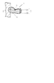
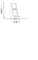
前記示温性クリップ1の構成として、一対の挟持片21、22が対向状に取付られ、中間部に配したバネ体3による弾圧力により、互いの先端部を近接方向に付勢された構造を例示できる(図1参照)。
ここで、前記一対の挟持片21、22は、内面中間部の突部で互いに軸支されており、前記突部近傍にコイルバネ又はU字形板バネ等のバネ体3が配されてなる、従来より公知の手段が適用できる。
挟持片2は、プラスチック、金属、木材、板紙等により適宜形状、寸法に形成される。
前記バネ体3による系は、対象物7或いは対象箇所の厚みの影響を受ける度合いが少ないので、多様な対象物に対して適正な挟持性を保持して適用できる。
As a configuration of the temperature indicating clip 1, a structure in which a pair of
Here, the pair of
The
Since the system using the spring body 3 is less affected by the thickness of the object 7 or the target portion, it can be applied to various objects while maintaining proper clamping.
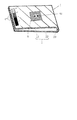
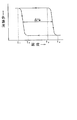
次に、一対の挟持片21、22が、中間部の屈曲部23を境に対向状に設けられた構造を例示できる(図2参照)。
ここで、互いの挟持片21、22は、プラスチック材又は金属材によって形成され、適正な挟持圧を先端部に発現させるため、互いの先端部は、後方より間隙を近接して形成される。
前記屈曲部23による系は、挟持片2を幅広、且つ大面積に形成でき、複数の検知温度を設定した感温変色層4を配することができ、色変化による視覚判別性に効果的に寄与する。
Next, a structure in which the pair of
Here, the
In the system using the
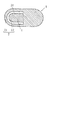
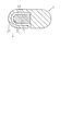
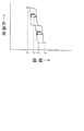
更には、一対の挟持片2が、プラスチック材又は金属材による板状の成形体であり、第2の挟持片22が、第1の挟持片21の内縁基端部を残して配した間隙部24を境として区分される小挟持片を設けた構造を例示できる(図3、図4参照)。
ここで、前記内縁基端部の近傍を段状の折曲起立部となして、肉厚の対象物の挿入性の向上を図ることができる。
前記小挟持片の内在の系は、一体加工により形成でき、生産性を満たす。
Furthermore, the pair of
Here, the vicinity of the inner edge base end portion can be used as a stepped bent upright portion to improve the insertability of a thick object.
The internal system of the small clamping piece can be formed by integral processing and satisfies the productivity.
前記した一対の挟持片21、22の少なくとも一方の挟持片には、以下に例示する熱変色性顔料を色材として適用し、感温変色層4が形成される。
前記熱変色性顔料は、従来より公知の(イ)電子供与性呈色性有機化合物、(ロ)電子受容性化合物、及び(ハ)前記両者の呈色反応の生起温度を決める反応媒体、の必須三成分を含む可逆熱変色性組成物をマイクロカプセル中に内包させた、マイクロカプセル形態の顔料が有効であり、発色状態からの加熱により消色する加熱消色型としては、本出願人が提案した、特公昭51−44706号公報、特公昭51−44707号公報、特公平1−29398号公報等に記載のものが利用できる。
前記顔料は、図5の温度ー色濃度曲線に示す如く、所定の温度(変色点)を境としてその前後で変色し、高温側完全変色温度(t4 )以上の温度域で消色状態を呈し、低温側完全変色温度(t1 )以下の温度域で発色状態を呈し、前記両状態のうち常温域では特定の一方の状態しか存在しない。即ち、もう一方の状態は、その状態が発現するのに要した熱又は冷熱が適用されている間は維持されるが、前記熱又は冷熱の適用がなくなれば常温域で呈する状態に戻る、ヒステリシス幅が比較的小さい特性(ΔHA =1〜8℃)を有する。
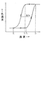
又、加熱消色型熱変色性顔料として、本出願人が提案した特公平4−17154号公報、特開平7−179777号公報、特開平7−33997号公報、特開平8−39936号公報等、大きなヒステリシス特性(ΔHB =8〜80℃)を示す、即ち、温度変化による着色濃度の変化をプロットした曲線の形状が、温度を変色温度域より低温側から上昇させていく場合と、逆に変色温度域より高温側から下降させていく場合とで大きく異なる経路を辿って変色し、低温側完全変色温度(t1 )以下の低温域での発色状態、又は高温側完全変色温度(t4 )以上の高温域での消色状態が、特定温度域〔t2 〜t3 の間の温度域(実質的二相保持温度域)〕で互変化的に記憶保持できる色彩記憶保持型熱変色性顔料も利用できる(図6参照)。
更には、加熱発色型熱変色性顔料として、消色状態からの加熱により発色し、温度降下により消色する、本出願人の提案による、電子受容性化合物として、炭素数3乃至18の直鎖又は側鎖アルキル基を有する特定のアルコキシフェノール化合物を適用した系(特開平11−129623号公報、特開平11−5973号公報)、特定のヒドロキシ安息香酸エステルを適用した系(特開2001−105732号公報)、更には、特定の没食子酸エステル等を適用した系(特開2003−253149号公報)等を応用できる(図7参照)。
A thermochromic pigment exemplified below is applied as a color material to at least one of the pair of
The thermochromic pigment is a conventionally known (a) electron donating color-forming organic compound, (b) an electron-accepting compound, and (c) a reaction medium that determines the temperature at which the color reaction of both occurs. A pigment in the form of a microcapsule, in which a reversible thermochromic composition containing the essential three components is encapsulated in a microcapsule, is effective. The proposed ones described in JP-B-51-44706, JP-B-51-44707, JP-B-1-29398 and the like can be used.
As shown in the temperature-color density curve of FIG. 5, the pigment discolors before and after a predetermined temperature (discoloration point), and exhibits a decolored state in a temperature range above the high temperature side complete discoloration temperature (t 4 ). It exhibits a colored state in the temperature range below the complete color change temperature (t 1 ) on the low temperature side, and only one specific state exists in the normal temperature range among the two states. That is, the other state is maintained while the heat or cold necessary to develop the state is applied, but when the heat or cold is not applied, the state returns to the state exhibited in the normal temperature range. The width is relatively small (ΔH A = 1-8 ° C.).
Further, as a heat-decoloring type thermochromic pigment, Japanese Patent Publication No. 4-17154, Japanese Patent Application Laid-Open No. 7-179777, Japanese Patent Application Laid-Open No. 7-33997, Japanese Patent Application Laid-Open No. 8-39936, etc. proposed by the present applicant. , Showing a large hysteresis characteristic (ΔH B = 8 to 80 ° C.), that is, the shape of the curve plotting the change of the color density due to the temperature change is opposite to the case where the temperature is raised from the lower temperature side than the color change temperature range. The color changes by following a very different path from the case where the temperature is lowered from the high temperature side to the color change temperature range, and the color development state in the low temperature range below the low temperature side complete color change temperature (t 1 ) or the high temperature side complete color change temperature (t 4 ) Color memory retention type heat in which the decolored state in the above high temperature range can be stored and retained in a specific temperature range [temperature range between t 2 and t 3 (substantially two-phase retention temperature range)]. A color-changing pigment can also be used (see FIG. 6).
Furthermore, as an electron-accepting compound proposed by the present applicant that develops color by heating from a decolored state as a heat-colorable thermochromic pigment, and decolorizes by a temperature drop, a straight chain having 3 to 18 carbon atoms. Alternatively, a system to which a specific alkoxyphenol compound having a side chain alkyl group is applied (Japanese Patent Laid-Open Nos. 11-129623 and 11-5973), a system to which a specific hydroxybenzoic acid ester is applied (Japanese Patent Laid-Open No. 2001-105732). In addition, a system to which a specific gallic acid ester or the like is applied (Japanese Patent Laid-Open No. 2003-253149) can be applied (see FIG. 7).
本発明で適用する顔料は、前記加熱消色型熱変色性顔料(色彩記憶保持型を含む)のうち、高温側変色開始温度(t3 )と高温側完全変色温度(t4 )との間、又は、低温側変色開始温度(t2 )と低温側完全変色温度(t1 )との間の各過渡的変色温度域の温度幅が、1〜10℃の範囲にあるものが有効である。
前記温度幅が1〜3℃の範囲の系は、高感度の変色性を示して完全変色状態に移行し、変色過渡期における中間色を視覚させ難いが、温度幅が概ね3℃を超えると変色過渡期の様相を緩徐に視覚させて完全変色状態に移行し、一方、温度幅が10℃を超えると色彩変化に伴う様相変化が緩慢に過ぎて温度の識別効果を満たし難い。
前記過渡的変色温度域の温度幅が3〜10℃の系における、単一の熱変色性顔料による有色−無色の系では、中間の色濃度を視覚させ、変色特性の異なる複数の熱変色性顔料を併用した系では、多段変色の様相を視覚させ、非熱変色性着色剤を併存させた系では、有色(1)−有色(2)間の中間色を視覚させる(図8参照)。
過渡的変色温度域における色濃度は、温度−色濃度曲線(図5、図6、図7、図8参照)にみられるように、完全変色前後の中間的色濃度を呈し、前記多段変色の系では色相の変化に伴う様相を多段的に視覚させる。
前記低温側完全変色温度(t1 )は、−30℃〜+20℃の範囲、高温側完全変色温度(t4 )は、20℃〜90℃の範囲から選ばれる任意の温度に設定できる。
尚、加熱発色型熱変色顔料の系では、前記(t3 )と(t4 )、(t2 )と(t1 )の各関係を、それぞれ(T3 )と(T4 )、(T2 )と(T1 )の関係に置き換えて、過渡的変色温度域における効果を説明できる。
The pigment to be applied in the present invention is a temperature between the high temperature side color change starting temperature (t 3 ) and the high temperature side complete color change temperature (t 4 ) among the heat decoloring type thermochromic pigments (including the color memory retention type). Alternatively, it is effective that the temperature range of each transitional discoloration temperature region between the low temperature side color change start temperature (t 2 ) and the low temperature side complete color change temperature (t 1 ) is in the range of 1 to 10 ° C. .
The system having a temperature range of 1 to 3 ° C shows a highly sensitive discoloration and shifts to a completely discolored state, making it difficult to see the intermediate color during the discoloration transition period, but discoloration when the temperature range exceeds approximately 3 ° C. The transitional phase is slowly visualized to shift to a completely discolored state. On the other hand, when the temperature width exceeds 10 ° C., the mode change accompanying the color change is too slow to satisfy the temperature discrimination effect.
In a colored-colorless system using a single thermochromic pigment in a system where the temperature range of the transitional color temperature range is 3 to 10 ° C., a plurality of thermochromic properties having different color-changing characteristics can be obtained by visualizing an intermediate color density. In the system using the pigment in combination, the appearance of multistage discoloration is visualized, and in the system in which the non-thermochromic colorant coexists, an intermediate color between colored (1) and colored (2) is visualized (see FIG. 8).
As shown in the temperature-color density curve (see FIGS. 5, 6, 7, and 8), the color density in the transitional color change temperature range exhibits an intermediate color density before and after complete color change, In the system, the appearance accompanying the change in hue is visualized in multiple stages.
The low temperature side complete color change temperature (t 1 ) can be set to an arbitrary temperature selected from the range of −30 ° C. to + 20 ° C., and the high temperature side complete color change temperature (t 4 ) can be selected from the range of 20 ° C. to 90 ° C.
In the heat coloring type thermochromic pigment system, the relationships (t 3 ) and (t 4 ), (t 2 ) and (t 1 ) are represented by (T 3 ), (T 4 ), (T By substituting the relationship between 2 ) and (T 1 ), the effect in the transitional discoloration temperature region can be explained.
本発明に適用するマイクロカプセル顔料5は、円形断面の形態のものの適用を拒まないが、非円形断面の形態(図9参照)のものが効果的である。
前記非円形断面の形態のマイクロカプセル顔料5は、外力の付加に対して外力を緩和する形状に微妙に弾性変形し、マイクロカプセル顔料5の壁膜aの破壊が抑制され、熱変色機能を損なうことなく有効に発現させることができる。ここで、非円形断面形状のマイクロカプセル顔料5は、最大外径の平均値が1〜30μmの範囲にあり、且つ可逆熱変色性組成物/壁膜=7/1〜1/1(重量比)の範囲を満たしたものが有効である。
The
The
前記マイクロカプセル顔料5(円形断面形状のものを含む)は、最大外径の平均値が、30μmを超える系では、加工適性、分散安定性の低下を来し、一方、最大外径の平均値が、1μm未満の系では高濃度の発色性を示し難く、最大外径の平均値が、5〜20μmの範囲が好適である。
可逆熱変色性組成物cの壁膜aに対する比率が前記範囲より大になると、壁膜aの厚みが肉薄となり過ぎ、圧力や熱に対する耐性の低下を来し、逆に、壁膜aの可逆熱変色性組成物cに対する比率が前記範囲より大になると発色時の色濃度及び鮮明性の低下を免れず、好適には、可逆熱変色性組成物/壁膜=6/1〜1/1(重量比)である。
The microcapsule pigment 5 (including those having a circular cross-sectional shape) has a decrease in processability and dispersion stability when the average value of the maximum outer diameter exceeds 30 μm, while the average value of the maximum outer diameter. However, in a system having a size of less than 1 μm, it is difficult to exhibit high density color development, and the average value of the maximum outer diameter is preferably in the range of 5 to 20 μm.
When the ratio of the reversible thermochromic composition c to the wall film a is larger than the above range, the wall film a becomes too thin, resulting in a decrease in resistance to pressure and heat. When the ratio to the thermochromic composition c is larger than the above range, the color density and sharpness during color development are unavoidable, and preferably the reversible thermochromic composition / wall film = 6/1 to 1/1. (Weight ratio).
前記可逆熱変色性組成物cのマイクロカプセル化は、界面重合法、界面重縮合法、in−Situ重合法、コアセルベート法等の公知の手段が適用できるが、本発明の前記した要件を満たす粒子径範囲の、非円形断面形状のマイクロカプセル顔料5を得るためには、凝集、合一化が生じ難い界面重合法又は界面重縮合法を適用することができる。
For the microencapsulation of the reversible thermochromic composition c, known means such as an interfacial polymerization method, an interfacial polycondensation method, an in-situ polymerization method, a coacervate method, etc. can be applied, but the particles satisfying the above-mentioned requirements of the present invention In order to obtain the
挟持片2の少なくとも一方に配設される感温変色層4は、前記した熱変色性顔料5をバインダ─樹脂100重量部に対して、20〜400重量部(好適には、30〜300重量部)の割合で分散状態で固着させた、10〜400μm(好ましくは、15〜200μm)の厚みが有効であり、従来より公知の塗布、印刷、スプレ─等の手段により、挟持片2の表面に形成される。
The temperature-sensitive color-changing layer 4 disposed on at least one of the
前記におけるバインダ─樹脂は、例えば、各種合成樹脂エマルジョン、水溶性乃至油溶性の合成樹脂、紫外線硬化樹脂等、従来より汎用の各種バインダ─が有効である。
前記において、熱変色性顔料の割合が20重量部未満では、鮮明な色変化を示さず、一方、400重量部を超えると消色時に残色を生じがちである。
前記感温変色層4は、単層に限らず、熱変色特性が相異なる複数層を積層したものが有効であり、更には、上層又は下層に非熱変色性着色層6を設けることができる。又、変色温度を異にする感温変色層4を並設したものが有効である。
ここで、前記感温変色層4は、紙、プラスチックシート材に予め印刷形成されたものを挟持片2の表面に貼付して形成することができる。
尚、前記感温変色層4及び非熱変色性着色層6は、ベタ印刷に限らず、文字、記号、英数字、顔文字、図柄、語句等の像61であってもよい。
As the binder resin, for example, various conventional binders such as various synthetic resin emulsions, water-soluble or oil-soluble synthetic resins, and ultraviolet curable resins are effective.
In the above, when the ratio of the thermochromic pigment is less than 20 parts by weight, a clear color change is not exhibited, while when it exceeds 400 parts by weight, a residual color tends to be generated during decoloring.
The temperature-sensitive color-changing layer 4 is not limited to a single layer, and a layer in which a plurality of layers having different thermochromic properties are laminated is effective. Further, a non-thermochromic
Here, the temperature-sensitive color changing layer 4 can be formed by sticking a surface of the
The temperature-sensitive color changing layer 4 and the non-thermochromic
挟持片2が熱可塑性プラスチック材による系では、熱変色性顔料5を前記プラスチック材に対して、0.1〜30重量%の範囲(好ましくは、5〜20重量%)でブレンドして一体成型されたものを適用できる。0.1重量%未満では、色濃度が不十分であり、30重量%を超えると顕著な色濃度の向上がみられない上、消色時の残色を発生させる。
熱変色特性が異なる複数の熱変色性顔料や非熱変色性着色剤等の適宜量を併存させることができる。
In a system in which the
Appropriate amounts of a plurality of thermochromic pigments and non-thermochromic colorants having different thermochromic properties can coexist.
前記感温変色層4中には、非熱変色性着色剤として、汎用の着色顔料に限らず、蛍光顔料、蓄光顔料、金属光沢顔料、コレステリック液晶型光輝性顔料等を配合して色彩効果を高めることができる。更には、香料成分を配合して温度の色変化による識別性に加えて芳香性を付与することができる。 The temperature-sensitive color changing layer 4 is not limited to a general-purpose color pigment as a non-thermochromic colorant, but includes a fluorescent pigment, a phosphorescent pigment, a metallic luster pigment, a cholesteric liquid crystal-type glitter pigment, and the like to achieve a color effect. Can be increased. Furthermore, a fragrance | flavor component can be mix | blended and aromaticity can be provided in addition to the discriminability by the color change of temperature.
本発明は、前記したとおり、感温変色性の挟持片2を介して対象物7、或いは対象箇所の温度を色変化により視覚判別させるものであり、前記挟持片2の伝熱性に依存して、感温変色域を徐々に拡大させて、加熱又は冷却の適正状態を色変化により視覚判別させることができる。
前記挟持片2の伝熱性は、材質の選択に依存するが、同一材質にあっては、形状、大きさ等を目的に合せて設定することにより、前記効果を奏することができる。
以下に実施例を示す。尚、実施例中の部は重量部である。
As described above, the present invention visually discriminates the temperature of the object 7 or the target portion by the color change through the temperature-sensitive color-changing
The heat conductivity of the
Examples are shown below. In addition, the part in an Example is a weight part.
実施例1
発色状態で青色を呈し、加熱により消色する加熱消色型熱変色性顔料〔高温側変色点(t3 :30℃、t4 :32℃)、低温側変色点(t1 :26℃、t2 :28℃)〕の5部とポリプロピレン樹脂95部の比率で均質に溶融混合して得られた熱変色性ペレットを用いて、射出成型により一対の挟持片21、22を得た。前記挟持片21、22にバネ体3(コイルバネ)を取り付けて示温性クリップ1を構成した(図1参照)。
温度変化による様相変化
高温側変色開始温度(t3 :30℃)と高温側完全変色温度(t4 :32℃)との間、及び低温側変色開始温度(t2 :28℃)と低温側完全変色温度(t1 :26℃)との間の各過渡的変色温度域において、過渡的な淡青色を実質的に視覚させることなく、直ちに無色の様相を視覚判別させた。
(適用例)
前記示温性クリップ1を室内のカーテン、ブラインドにクリップし、室内温度管理用として適用した。
前記示温性クリップ1は、室内温度が32℃以上で無色、26℃以下では、青色を呈し室内温度調整の目安となった。前記変色の様相は、繰り返しの適用において再現された。
Example 1
Heat-erasable type thermochromic pigment which exhibits blue in a colored state and is decolored by heating [high temperature side color change point (t 3 : 30 ° C., t 4 : 32 ° C.), low temperature side color change point (t 1 : 26 ° C., t 2 : 28 ° C.)] and a thermochromic pellet obtained by uniformly melting and mixing at a ratio of 95 parts of polypropylene resin, a pair of sandwiching
Aspect change due to temperature change Between high temperature side discoloration start temperature (t 3 : 30 ° C) and high temperature side complete color change temperature (t 4 : 32 ° C), and low temperature side discoloration start temperature (t 2 : 28 ° C) and low temperature side In each transitional discoloration temperature region between the complete discoloration temperature (t 1 : 26 ° C.), the colorless aspect was immediately discriminated without substantially visualizing the transient light blue color.
(Application example)
The temperature indicating clip 1 was clipped to an indoor curtain or blind and applied for indoor temperature management.
The temperature-indicating clip 1 was colorless when the room temperature was 32 ° C. or higher, and blue when the room temperature was 26 ° C. or lower, which was a measure for adjusting the room temperature. The discoloration aspect was reproduced in repeated applications.
実施例2
発色状態で青色を呈し、加熱により消色する加熱消色型熱変色性顔料〔高温側変色点(t3 :32℃、t4 :36℃)、低温側変色点(t1 :24℃、t2 :30℃)〕5部、非熱変色性ピンク色顔料1部とポリプロピレン樹脂94部の比率で均質に溶融混合して得られた熱変色性ペレットを用いて、射出成型により一対の挟持片21、22を得た。前記挟持片21、22にバネ体3(コイルバネ)を取り付けて示温性クリップ1を構成した(図1参照)。
温度変化による様相変化
高温側変色開始温度(t3 :32℃)と高温側完全変色温度(t4 :34℃)との間、及び低温側変色開始温度(t2 :30℃)と低温側完全変色温度(t1 :24℃)との間の各過渡的変色温度域において中間色を経て、ピンク色又は紫色に緩徐に変化する様相を視覚させた。
(適用例)
前記示温性クリップ1を陶器製食品容器の上縁にクリップし、容器温度確認用として適用した。
前記示温性クリップ1は、容器が空の状態では、紫色を呈し、容器内に加熱調理した食品を入れると徐々にピンク色に変化し、容器温度が上昇していることが目視で判別できた。前記様相の変化は、繰り返し再現できた。
Example 2
Heat-decolorable thermochromic pigment that exhibits blue in a colored state and decolors by heating [high-temperature side color change point (t 3 : 32 ° C., t 4 : 36 ° C.), low-temperature side color change point (t 1 : 24 ° C., t 2 : 30 ° C)] 5 parts, a pair of non-thermochromic pink pigments and 94 parts of polypropylene resin, and a pair of sandwiched by injection molding using thermochromic pellets obtained by homogeneous
Aspect change due to temperature change Between high temperature side discoloration start temperature (t 3 : 32 ° C) and high temperature side complete discoloration temperature (t 4 : 34 ° C), and low temperature side discoloration start temperature (t 2 : 30 ° C) and low temperature side In each transitional discoloration temperature region between the complete discoloration temperature (t 1 : 24 ° C.), an appearance of slowly changing to pink or purple via an intermediate color was visualized.
(Application example)
The temperature-indicating clip 1 was clipped to the upper edge of a ceramic food container and applied for container temperature confirmation.
The temperature-indicating clip 1 is purple when the container is empty, and when the cooked food is put into the container, it gradually changes to pink, and it can be visually determined that the container temperature is rising. . The change in appearance could be repeated repeatedly.
実施例3
実施例1の加熱消色型熱変色性顔料に換えて、発色状態でピンク色を呈し、加熱により消色して消色状態に変移し、常温域で前記消色状態を保持し、冷却によりピンク色の発色状態に復し、常温域で発色状態を保持する色彩記憶型熱変色性顔料〔高温側変色点(t3 :26℃、t4 :31℃)、低温側変色点(t1 :13℃、t2 :18℃)〕を用いた以外は、実施例1と同様の方法にて示温性クリップ1を構成した(図1参照)。
温度変化による様相変化
前記示温性クリップ1は、常温域ではピンク色を呈し、26℃を超える温度域において、ピンク色の視覚濃度を緩徐に漸減させ、31℃以上では、完全に無色に変移し、18℃〜26℃の温度域では、無色の状態を維持し、18℃以下の温度域においては、ピンク色に緩徐に変化し、13℃以下で完全にピンク色に変移し、元の様相に復した。
(適用例)
前記示温性クリップ1を薬剤包装体の適所にクリップし、薬剤の保管温度確認用として適用した。
前記示温性クリップ1は、薬剤の適切な保管温度域である、18℃〜26℃の範囲において、択一的にピンク色、又は無色を呈し、31℃以上になると無色に、13℃以下になるとピンク色にそれぞれ変移し、不適切な保管温度で保管されたことを目視で判別できた。前記様相変化は、繰り返しの適用において、再現された。
Example 3
Instead of the heat decoloring type thermochromic pigment of Example 1, it exhibits a pink color in a colored state, decolored by heating and changed to a decolored state, maintained in the decolored state at room temperature, and cooled. Color memory type thermochromic pigment that returns to the pink color development state and maintains the color development state in the normal temperature range [high temperature side color change point (t 3 : 26 ° C., t 4 : 31 ° C.), low temperature side color change point (t 1 : 13 ° C., t 2 : 18 ° C.)] was used, and the temperature indicating clip 1 was constructed in the same manner as in Example 1 (see FIG. 1).
Change in appearance due to temperature change The temperature-indicating clip 1 exhibits a pink color at room temperature, gradually decreases the visual density of pink at temperatures exceeding 26 ° C, and changes completely colorless at temperatures above 31 ° C. In the temperature range of 18 ° C. to 26 ° C., it maintains a colorless state, and in the temperature range of 18 ° C. or less, it gradually changes to pink, and completely changes to pink at 13 ° C. or less. Reverted to.
(Application example)
The temperature-indicating clip 1 was clipped to an appropriate position of the medicine package and applied for checking the storage temperature of the medicine.
In the range of 18 ° C. to 26 ° C., which is an appropriate storage temperature range for the medicine, the thermophilic clip 1 is alternatively pink or colorless, and when it is 31 ° C. or higher, it is colorless and 13 ° C. or lower. Then, each color changed to pink, and it was visually determined that it was stored at an inappropriate storage temperature. The modal change was reproduced in repeated applications.
実施例4
実施例2の熱変色性ペレットを用いて、小挟持片内在の一体成型示温性クリップ1を構成した(図3参照))。
前記示温性クリップ1は、実施例2と同様の様相変化を呈した。
(適用例)
前記示温性クリップ1を犬、猫の耳にクリップし、ペットの簡易体温確認用として適用した。
前記示温性クリップ1は、ペットの体温(人間より平熱が約1℃高く、約38℃)により、紫色からピンク色に緩徐に変移し、変色具合により簡易にペットの健康状態を目視で確認できた。前記様相変化は、繰り返しの適用において、再現された。
Example 4
Using the thermochromic pellet of Example 2, an integrally molded temperature-indicating clip 1 with a small sandwiching piece was constructed (see FIG. 3)).
The temperature-indicating clip 1 exhibited the same change in appearance as in Example 2.
(Application example)
The temperature-indicating clip 1 was clipped to the ears of dogs and cats, and applied for simple body temperature confirmation of pets.
The temperature-indicating clip 1 slowly changes from purple to pink depending on the body temperature of the pet (normal heat is about 1 ° C higher than that of humans, about 38 ° C). It was. The modal change was reproduced in repeated applications.
実施例5
発色状態で橙色を呈する加熱消色型熱変色性顔料A〔高温側変色点(t3 :10℃、t4 :12℃)、低温側変色点(t1 :7℃、t2 :9℃)〕、発色状態で緑色を呈する加熱消色型熱変色性顔料B〔高温側変色点(t3 :20℃、t4 :22℃)、低温側変色点(t1 :17℃、t2 :19℃)〕、発色状態で青色を呈する加熱消色型熱変色性顔料C〔高温側変色点(t3 :30℃、t4 :32℃)、低温側変色点(t1 :27℃、t2 :29℃)〕、発色状態で黒色を呈する加熱消色型熱変色性顔料D〔高温側変色点(t3 :38℃、t4 :40℃)、低温側変色点(t1 :35℃、t2 :37℃)〕、の四種の熱変色性顔料各40部を、それぞれエチレンー酢酸ビニル共重合樹脂エマルジョン(固形分50重量%)を含む水性ビヒクル中に分散させた四種の感温変色性インキを得た。
次いで、白色合成紙(背面に粘着剤が塗布されてなる)の表面に前記四種の感温変色性インキを用いて、スクリーン印刷により方形状の四種の感温変色層4を配した印刷物を得た。
更に、前記熱変色性顔料Cの発色時に呈する青色と同色の非熱変色性着色層6及び非熱変色性黒色文字「適温」(像61)を前記と同様の白色合成紙表面に印刷形成した。
ポリプロピレン樹脂からなる、屈曲部23を備えた挟持片21、22の一体成型クリップの、挟持片21の先端部表面に前記四種の感温変色層4を設けた印刷物を貼付し、中央部表面に前記非熱変色性着色層6(青色)及び像61(黒色)の印刷物を貼付して、示温性クリップ1を構成した(図2参照)。
温度変化による様相変化
7℃以下では、前記四種の感温変色層4が発色して、橙色、緑色、青色、黒色の各方形状の着色を呈し、12℃、22℃、32℃、40℃を超えると、順次、前記各層における変色過渡期の様相を殆ど視覚させることなく無色に変移した様相を視覚させた。
(適用例)
前記示温性クリップ1を、適温の温度域管理用(22℃〜30℃)として適用した。
クリップした温度管理箇所の温度が、適温範囲にあると黒色及び青色が視覚され、22℃以下になると、黒色、青色に加えて緑色が視覚された。更に低温になると、橙色が視覚され、適温の温度域を下回っていることを視覚判別できた。一方、30℃を上回ると、青色が消え、黒色のみ視覚され、更に高温になると総てが消色状態になり、温度管理箇所が、適温の温度域を上回っていることを視覚判別させた。
ここで、前記の前記非熱変色性着色層6は、管理温度の指標の役目を果たし、像61は視覚判別性の表示効果を果たす。前記様相変化は、繰り返しの適用において、再現された。
Example 5
Heat-decolorable thermochromic pigment A that exhibits an orange color in a colored state [high-temperature side color change point (t 3 : 10 ° C., t 4 : 12 ° C.), low-temperature side color change point (t 1 : 7 ° C., t 2 : 9 ° C. )], A heat decoloring type thermochromic pigment B exhibiting a green color (high temperature side color change point (t 3 : 20 ° C., t 4 : 22 ° C.), low temperature side color change point (t 1 : 17 ° C., t 2) : 19 ° C.)], a heat-erasable thermochromic pigment C exhibiting a blue color in a colored state (high temperature side discoloration point (t 3 : 30 ° C., t 4 : 32 ° C.), low temperature side color change point (t 1 : 27 ° C.) , T 2 : 29 ° C.)], a heat-erasable thermochromic pigment D exhibiting black in a colored state [high temperature side color change point (t 3 : 38 ° C., t 4 : 40 ° C.), low temperature side color change point (t 1 : 35 ℃, t 2: 37 ℃) ], of the four types of thermochromic pigments each 40 parts of aqueous each containing ethylene-vinyl acetate copolymer resin emulsion (solid content 50 wt%) Bihiku To obtain four kinds of thermochromic ink dispersed in.
Next, a printed matter in which four types of temperature-sensitive color-changing layers 4 are arranged by screen printing on the surface of white synthetic paper (the back surface of which is coated with an adhesive) using the four types of temperature-sensitive color-changing inks. Got.
Further, the non-thermochromic
A printed material provided with the four types of temperature-sensitive color-changing layers 4 is pasted on the surface of the tip of the
Change in appearance due to temperature change Below 7 ° C., the four types of temperature-sensitive color changing layers 4 are colored and have orange, green, blue, and black coloration, 12 ° C., 22 ° C., 32 ° C., 40 ° C. When the temperature was higher than 0 ° C., the appearance of transition to colorless was made visible with little visual appearance of the appearance of the color transition period in each layer.
(Application example)
The temperature-indicating clip 1 was applied for temperature range management (22 ° C. to 30 ° C.) at an appropriate temperature.
When the temperature of the clipped temperature control point was within the appropriate temperature range, black and blue were visually recognized. When the temperature was 22 ° C. or lower, green was observed in addition to black and blue. When the temperature was further lowered, an orange color was visually recognized, and it was visually determined that the temperature was below the appropriate temperature range. On the other hand, when the temperature exceeded 30 ° C., the blue color disappeared and only black color was visually recognized, and when the temperature was further increased, all were in a decolored state, and it was visually discriminated that the temperature control points were above the appropriate temperature range.
Here, the non-thermochromic
実施例6
発色状態でピンク色を呈する加熱消色型熱変色性顔料〔高温側変色点(t3 :0℃、t4 :2℃)、低温側変色点(t1 :−3℃、t2 :−1℃)〕20部、発色状態で緑色を呈する加熱消色型熱変色性顔料〔高温側変色点(t3 :10℃、t4 :12℃)、低温側変色点(t1 :7℃、t2 :9℃)〕20部、非熱変色性黄色顔料5部をウレタン系樹脂(固形分35重量%)を含む水性ビヒクル中に分散させた感温変色性インキにより、白色合成紙(背面に粘着剤を塗布してなる)の表面に円形状の感温変色層4を形成し、その上層に透明ポリプロピレン樹脂にてラミネート処理を施し、感温変色性印刷物を得た。
ポリエステル樹脂からなる、小挟持片内在の一体成型クリップの挟持片22の表面に前記感温変色性印刷物を貼付して示温性クリップ1を構成した(図4参照)。
温度変化による様相変化
−3℃以下では、黒色、2℃を超えると緑色、12℃を超えると黄色の円形状の感温変色層4に過渡的変色の様相を実質的に視覚させることなく変移した。
(適用例)
前記示温性クリップ1を食品等の温度管理用として適用し、包装体の外面の適所をクリップすることにより、黄色状態では冷凍温度が高温で不適、緑色状態では冷凍温度が適温、黒色状態では過冷状態であることを、目視による色変化により視覚判別できた。
前記様相変化は、繰り返しの適用において、再現された。
Example 6
Heat-decolorable thermochromic pigment exhibiting pink color in the color development state [high temperature side color change point (t 3 : 0 ° C., t 4 : 2 ° C.), low temperature side color change point (t 1 : −3 ° C., t 2 : − 1 part), 20 parts, heat decoloring type thermochromic pigment exhibiting green color (high temperature side discoloration point (t 3 : 10 ° C., t 4 : 12 ° C.), low temperature side discoloration point (t 1 : 7 ° C.) , T 2 : 9 ° C.)] 20 parts, 5 parts of non-thermochromic yellow pigment was dispersed in an aqueous vehicle containing a urethane resin (solid content 35% by weight) using a temperature-sensitive color-changing ink to produce white synthetic paper ( A circular temperature-sensitive color-changing layer 4 was formed on the surface of the back surface (applied with an adhesive), and the upper layer was laminated with a transparent polypropylene resin to obtain a temperature-sensitive color-changing printed matter.
The temperature-indicating clip 1 was constructed by sticking the temperature-sensitive color-changing printed matter to the surface of the
Change in appearance due to temperature change Less than -3 ° C, transition to black without exceeding 2 ° C, green color above 12 ° C, and yellow to 12 ° C. did.
(Application example)
By applying the temperature-indicating clip 1 for temperature control of foods and the like, and clipping the appropriate place on the outer surface of the package, the freezing temperature is unsatisfactory when it is yellow, the refrigerating temperature is appropriate when it is green, and excessive when it is black The cold state could be visually discriminated by visual color change.
The modal change was reproduced in repeated applications.
実施例7
発色状態でピンク色を呈する加熱消色型熱変色性顔料〔高温側変色点(t3 :0℃、t4 :2℃)、低温側変色点(t1 :−3℃、t2 :−1℃)〕8部、発色状態で緑色を呈する加熱消色型熱変色性顔料〔高温側変色点(t3 :10℃、t4 :12℃)、低温側変色点(t1 :7℃、t2 :9℃)〕8部、非熱変色性黄色顔料2部をアクリル系樹脂(固形分50重量%を含むキシレン溶液)50部、メチルイソブチルケトン30部を攪拌混合した塗料を用いて、アクリロニトリル−ブタジエン−スチレン共重合体からなる、小挟持片を内在一体成型したクリップの挟持片22の表面にスプレーガンでスプレー塗装して、感温変色層4を備えた示温性クリップ1を構成した(図3参照)。
前記示温性クリップ1は、実施例6と同様の変色挙動を呈し、冷凍食品の温度管理用に適用した。
Example 7
Heat-decolorable thermochromic pigment exhibiting pink color in the color development state [high temperature side color change point (t 3 : 0 ° C., t 4 : 2 ° C.), low temperature side color change point (t 1 : −3 ° C., t 2 : − 8 parts, heat decoloring type thermochromic pigment exhibiting green color (high temperature side discoloration point (t 3 : 10 ° C., t 4 : 12 ° C.), low temperature side discoloration point (t 1 : 7 ° C.) , T 2 : 9 ° C.)] 8 parts, 2 parts of non-thermochromic yellow pigment, 50 parts of acrylic resin (xylene solution containing 50% by weight of solid content), and 30 parts of methyl isobutyl ketone were mixed with stirring. A temperature-indicating clip 1 having a temperature-sensitive discoloration layer 4 is constructed by spray-coating with a spray gun on the surface of a
The temperature-indicating clip 1 exhibited a discoloration behavior similar to that in Example 6, and was applied for temperature control of frozen food.
実施例8
常温で消色状態であり、加熱により青色を呈する加熱発色型熱変色性顔料〔高温側変色点(T3 :32℃、T4 :40℃)、低温側変色点(T1 :22℃、T2 :30℃)〕の5部、非熱変色性ピンク色顔料1部をポリオレフィン系樹脂94部に分散状態に溶融ブレンドされた熱変色性ペレットを用いて、小挟持片の内在一体成型の示温性クリップ1を構成した(図3参照)。
温度変化による様相変化
常温域では、ピンク色を呈し、加熱により青色の発色状態への移行に伴い、徐々に紫色に変化する過渡的変色移行状態を緩徐に視覚させて完全に紫色を呈した。
(適用例)
前記示温性クリップ1は食品の温度管理用として適用でき、食品の適正保管温度域では、ピンク色を呈し、保管温度が40℃を超えると徐々に紫色を呈して、食品の適正保管温度域を逸脱していることが簡便に目視により視覚判別できた。
前記様相変化は、繰り返しの適用において再現された。
Example 8
Heat-developing thermochromic pigment that is decolored at room temperature and exhibits a blue color upon heating [high-temperature side color change point (T 3 : 32 ° C., T 4 : 40 ° C.), low-temperature side color change point (T 1 : 22 ° C., 5 parts of T 2 : 30 ° C.) and 1 part of non-thermochromic pink pigment in 94 parts of polyolefin resin in a dispersed state and melt blended. A temperature indicating clip 1 was constructed (see FIG. 3).
Change in appearance due to temperature change In the normal temperature range, it showed a pink color, and with the transition to a blue color development state upon heating, the transitional color transition state gradually changing to purple was slowly visualized to give a complete purple color.
(Application example)
The temperature-indicating clip 1 can be used for temperature control of food, and in the proper storage temperature range of food, it exhibits a pink color, and gradually becomes purple when the storage temperature exceeds 40 ° C. It was possible to visually distinguish the deviation from the eye easily.
The modal change was reproduced in repeated applications.
実施例9
発色状態でピンク色を呈する加熱消色型熱変色性顔料〔高温側変色点(t3 :31℃、t4 :35℃)、低温側変色点(t1 :25℃、t2 :29℃)〕5部、非熱変色性黄色顔料1部、ポリプロピレン樹脂94部の比率で均質に溶融ブレンドして得られた熱変色性ペレットを用いて、射出成型により一対の挟持片21、22を得た。前記挟持片21、22にバネ体3(コイルバネ)を取り付けて示温性クリップ1を構成した(図1参照)。
温度変化による様相変化
高温側変色開始温度(t3 :31℃)と高温側完全変色温度(t4 :35℃)との間、及び低温側変色開始温度(t2 :29℃)と低温側完全変色温度(t1 :25℃)との間の各過渡的変色温度域において中間色を経て、赤色、又は黄色に緩徐に変化する様相を視覚させた。
(適用例)
前記示温性クリップ1を即席スープ入り樹脂性容器の開口縁部と蓋との合せ目にクリップし、適正加熱状態確認用として適用した。
前記示温性クリップ1は、クリップ初期には赤色を呈しており、前記樹脂容器内に熱湯を注ぐと徐々に黄色へと変色域を拡大させ、最終的にすべて黄色に変色して、容器内のスープの飲み頃となる、適正加熱条件(約1分)を目視で判別できた。
前記様相変化は、繰り返しの適用において再現された。
Example 9
Heat-decolorable thermochromic pigment exhibiting a pink color in a colored state [high temperature side color change point (t 3 : 31 ° C., t 4 : 35 ° C.), low temperature side color change point (t 1 : 25 ° C., t 2 : 29 ° C. )] 5 parts, 1 part of non-thermochromic yellow pigment, 94 parts of polypropylene resin, and using thermochromic pellets obtained by homogenous melt blending, a pair of sandwiched
Change in appearance due to temperature change Between high temperature side discoloration start temperature (t 3 : 31 ° C) and high temperature side complete discoloration temperature (t 4 : 35 ° C), and low temperature side discoloration start temperature (t 2 : 29 ° C) and low temperature side In each transitional discoloration temperature region between the complete discoloration temperature (t 1 : 25 ° C.), an appearance of slowly changing to red or yellow via a neutral color was visualized.
(Application example)
The temperature-indicating clip 1 was clipped at the joint between the opening edge of the instant soup-filled resin container and the lid, and applied for checking the proper heating state.
The temperature-indicating clip 1 is red in the initial stage of the clip, and when hot water is poured into the resin container, the discoloration region gradually expands to yellow, and finally all the color changes to yellow. Appropriate heating conditions (about 1 minute) that would make it easy to drink soup could be visually discriminated.
The modal change was reproduced in repeated applications.
1 示温性クリップ
2 挟持片
21 第1の挟持片
22 第2の挟持片
23 屈曲部
24 間隙部
3 バネ体
4 感温変色層
5 熱変色性マイクロカプセル顔料
6 非熱変色性着色層
61 像
7 対象物
a 壁膜
b 窪み
c 可逆熱変色性組成物
ΔHA ヒステリシス温度幅(加熱消色型)
ΔHB ヒステリシス温度幅(加熱消色−色彩記憶保持型)
ΔHC ヒステリシス温度幅(加熱発色型)
t1 加熱消色型マイクロカプセル顔料の低温側完全変色温度
t2 加熱消色型マイクロカプセル顔料の低温側変色開始温度
t3 加熱消色型マイクロカプセル顔料の高温側変色開始温度
t4 加熱消色型マイクロカプセル顔料の高温側完全変色温度
T1 加熱発色型マイクロカプセル顔料の低温側完全変色温度
T2 加熱発色型マイクロカプセル顔料の低温側変色開始温度
T3 加熱発色型マイクロカプセル顔料の高温側変色開始温度
T4 加熱発色型マイクロカプセル顔料の高温側完全変色温度
DESCRIPTION OF SYMBOLS 1 Temperature-indicating
ΔH B hysteresis temperature range (heat decoloration-color memory retention type)
ΔH C Hysteresis temperature range (heating coloring type)
t 1 Low temperature side complete discoloration temperature of heat decolorable microcapsule pigment t 2 Low temperature side discoloration start temperature of heat decolorable microcapsule pigment t 3 High temperature side discoloration start temperature of heat decolorable microcapsule pigment t 4 Heat decoloration High temperature side complete discoloration temperature of T type heated microcapsule pigment T 1 Heated color development type microcapsule pigment low temperature side complete color change temperature T 2 Heated color development type microcapsule pigment low temperature side color change start temperature T 3 Heated color development type microcapsule pigment high temperature side color change Starting temperature T 4 Complete color change temperature on the high-temperature side of the heating type microcapsule pigment
Claims (14)
Priority Applications (1)
| Application Number | Priority Date | Filing Date | Title |
|---|---|---|---|
| JP2004114316A JP2005299750A (en) | 2004-04-08 | 2004-04-08 | Heat sensitive clip |
Applications Claiming Priority (1)
| Application Number | Priority Date | Filing Date | Title |
|---|---|---|---|
| JP2004114316A JP2005299750A (en) | 2004-04-08 | 2004-04-08 | Heat sensitive clip |
Publications (1)
| Publication Number | Publication Date |
|---|---|
| JP2005299750A true JP2005299750A (en) | 2005-10-27 |
Family
ID=35331531
Family Applications (1)
| Application Number | Title | Priority Date | Filing Date |
|---|---|---|---|
| JP2004114316A Pending JP2005299750A (en) | 2004-04-08 | 2004-04-08 | Heat sensitive clip |
Country Status (1)
| Country | Link |
|---|---|
| JP (1) | JP2005299750A (en) |
Cited By (2)
| Publication number | Priority date | Publication date | Assignee | Title |
|---|---|---|---|---|
| JP2012509818A (en) * | 2008-11-25 | 2012-04-26 | アジェンデ・キミケ・リウニテ・アンジェリニ・フランチェスコ・ア・チ・エレ・ア・エフェ・ソシエタ・ペル・アチオニ | Packaging material having a coloring element that partially erases color at a predetermined temperature to expose the marking, and a method for producing the same |
| KR101704285B1 (en) * | 2015-11-13 | 2017-02-08 | 강곤 | Overload identification menber of compression terminal, compression terminal having identification menber, and manufacturing method of compression terminal |
-
2004
- 2004-04-08 JP JP2004114316A patent/JP2005299750A/en active Pending
Cited By (2)
| Publication number | Priority date | Publication date | Assignee | Title |
|---|---|---|---|---|
| JP2012509818A (en) * | 2008-11-25 | 2012-04-26 | アジェンデ・キミケ・リウニテ・アンジェリニ・フランチェスコ・ア・チ・エレ・ア・エフェ・ソシエタ・ペル・アチオニ | Packaging material having a coloring element that partially erases color at a predetermined temperature to expose the marking, and a method for producing the same |
| KR101704285B1 (en) * | 2015-11-13 | 2017-02-08 | 강곤 | Overload identification menber of compression terminal, compression terminal having identification menber, and manufacturing method of compression terminal |
Similar Documents
| Publication | Publication Date | Title |
|---|---|---|
| EP1323540B1 (en) | Thermally color-developing reversibly thermochromic pigment | |
| US9464944B2 (en) | Temperature range compliance indicator | |
| JP3726217B2 (en) | Temperature-sensitive color change color memory microcapsule pigment | |
| JP2007332232A (en) | Thermochromic hysteresis composition | |
| JP7675656B2 (en) | Thermochromic Temperature Sensor | |
| US20020056991A1 (en) | Product label | |
| JPH11248552A (en) | Temperature control member and temperature control method | |
| JP5149655B2 (en) | Multi-stage discoloration temperature indicator | |
| JP2005299750A (en) | Heat sensitive clip | |
| JP2002064603A (en) | Reversible temperature-sensing discoloring portable telephone | |
| JP2002181637A (en) | Thermosensitive discoloring suitable temperature display heat storage body | |
| JP2001247828A (en) | Reversible temperature sensitive color changing pressure sensitive adhesive tape | |
| JP2001234134A (en) | Reversible temperature sensitive color changing pressure sensitive adhesive tape | |
| JP2002294127A (en) | Thermal ink and temperature history indicator using the same | |
| JPH0740660A (en) | Reversible, color-variable, temperature-sensitive recording composition | |
| JP2003315167A (en) | Irreversible thermochromic indicator for temperature history detection | |
| JP2002181635A (en) | Heating temperature confirmation indicator | |
| JP2002206972A (en) | Temperature-sensitive discoloring type appropriate temperature range indicator | |
| US6361839B1 (en) | Hot stamping foil and process | |
| JP3172809B2 (en) | Thermochromic laminate and composition and sheet used to produce this laminate | |
| JP2000080359A (en) | Temperature sensitive and reversibly multi-color changeable composition and laminated body | |
| JP2000080360A (en) | Temperature sensitive and reversibly multi-color changeable composition and laminated body | |
| JP2001121642A (en) | Metal gloss like thermosensitive color-changeable/heat- shrinkable plastic film | |
| JPH10146204A (en) | Thermosensitive discoloring footwear | |
| JP2005014585A (en) | Grip for temperature-sensitive color changeable writing implement, writing implement equipped with it and writing implement set |